one world trade centerproducts.rfsworld.com/userfiles/white_papers/2017/one-world-trade... · –...
TRANSCRIPT

Building an Advanced Customizable
RF Transmission System at
One World Trade Center
Photo: ©2016 John M. Lyons
This paper appears in the Proceedings of the 2017 Broadcast Engineering and Information Technology Conference, and is being
shared with permission from the National Association of Broadcasters (NAB). Copyright 2017, all rights reserved. ISBN # 978-0-89324-009-7.

1
Part 1 IntroductIon and HIstory– John Lyons, Director of Broadcast Communications,
The Durst Organization, New York, NY
Broadcasting from atop the original One World Trade Center (One WTC) started shortly after construction of the antenna was completed in 1978 and continued until that fateful day of September 11, 2001.
Original Broadcast Spire Under Construction – Photo Courtesy of Alan Reiss PANYNJ
It was home to most of the New York City TV stations and four of its FM stations at the time of 9/11. Within a short time, WCBS, which had a backup transmitter at the Empire State Building and WNBC, using the facilities of WNYE-TV were back on the air, with the other TV stations scrambling to build facilities at the Alpine Tower in New Jersey, the Empire State Building and at 4 Times Square. Univision Television had relocated from the World Trade Center facility in the early 90’s and was also operational at the time. Two of the four FM Radio Stations were relocated on the FM Master Antenna and the Alford Backup Antenna within a few days, with two of the FM stations, WNYU and WKCR, relocating to WNYU and Columbia University buildings.A few months later, I was hired by The Durst Organization to head up a rebuilding project at 4 Times Square (4TS) tasked with changing out the 132’ FM tower to a new 385’ TV and FM tower capable of providing primary or backup facilities for all of the TV and FM stations in the New York City market. The new tower was topped out on October 2, 2003 and WABC-TV started broadcasting there three weeks later, having relocated to the Alpine Tower after 9/11. The tower at 4TS is now 416’ having changed out the defunct Channel 68 antenna with a new Channel 3 antenna during the summer of 2014.
“Building the advanced customizable RF transmission system at One World Trade Center”
The Story Of The Build By The Team That Did It.
IntroductIon When the World Trade Center towers fell, the RF transmission systems of 13 New York City area television stations were destroyed. Although that tragedy happened 15 years ago, this story is again timely, because RF transmission will be returning to One World Trade Center, fully commissioned, one month after NAB 2017. As the Durst Organization began designing this system, factored into the plan was the unpredictability of the spectrum auction, new requirements for ATSC 3.0, and accommodation for delivery to mobile devices. Durst utilized new technology to give New York City broadcasters greater signal management flexibility to cope with these new challenges.
PanelIstsJohn Lyons, Director of Broadcast Communications, The Durst Organization – Managed the project for The Durst Organization
Phil Cindrich, President, MYAT, Inc. – Equipment integrator and transmission line supplier
Nick Wymant, CTO Broadcast Division, Radio Frequency Systems – Provided antenna and combiner technology
Jim Graf, President, Skyline Towers – Supervised all rigging
Josh Gordon, Broadcast Consultant – Moderated the panel and coordinated the
presentation

2
Moving Forward At One World Trade CenterThe Metropolitan Television Alliance (MTVA) began discussions with the Port Authority of New York and New Jersey shortly after things settled down in the aftermath of 9/11 but they broke down in 2008.The Durst Organization (TDO) partnered with the PANYNJ in 2010 in a joint-venture partnership including leasing and management of the building and rights to the spire/rooftop for broadcasting and other telecommunications. TDO held many meetings with the MTVA, representing the TV broadcasters and the Master FM Broadcast Committee (FM Broadcasters) to develop a plan for installing a broadcast transmitting facility atop One WTC.
After many discussions, a decision was finally made to install test VHF and UHF antennas on the spire to have empirical test results on the coverage from One WTC. The test antenna contract was awarded to Myat Inc., working with their antenna supplier RFS, as well as East Coast Hoist and Hatzel & Buehler electrical contractors, who performed the installation.Testing commenced in the Spring of 2015 with a very positive outcome turning into License Agreements with 4 TV broadcasters just before the end of the year. The project to build the permanent antennas began immediately with the design for mounting the antennas on the spire by Turris Engineering of New Jersey, rigging by Skyline Tower (East Coast Hoist) of Pennsylvania, 3-D modeling and drawing packages by Hanson Architects and Engineers of New Jersey and, transmission line and antenna installation by Hatzel & Buehler of New York and Delaware. Tishman Construction Corporation handled the overall project management for The Durst Organization with John Whitty and Jim Cornell serving as the Durst internal project team.The antenna and transmission line contract and was awarded to Myat, Inc and their partner RFS. The combiner contract was awarded to RFS and they immediately commenced final designs and construction. The first two TV antennas, the PEP40 UHF and the 662-16D CP VHF, were ready for factory acceptance testing in March
2016, with the PEP96 UHF antenna ready two months later. The UHF combiners were then manufactured and testing was performed in December 2016 and February 2017. The first PEP40 antenna panels were installed August 31, 2016 with the antenna, at publication date, scheduled to be operational by March 1, 2017. All transmission lines in the facility are manufactured by MYAT, Inc. of New Jersey.
Antenna Panels being rigged – Photo Credit: © John M Lyons 2016
First UHF Power Divider being hoisted – Photo Credit: © John M Lyons 2016
Spire Sections at dock in New Jersey, December 7, 2012 – Photo Credit: © John M Lyons 2016

3
Part 2 Equipment Coordination And Transmission Line Installation– Phil Cindrich, President of MYAT, Mahwah, NJ
Myat, Inc. was fortunate to be involved with the One World Trade Center project from a very early stage. Once the decision was made to return a broadcast transmission facility to lower Manhattan, we knew that The Durst Organization would aim to provide a state-of the-art, future-ready solution for the New York broadcasts. This meant, among other things, a system designed to provide superior market coverage, independently customizable circular and/or elliptical polarization options for each broadcaster, and the availability of full local, as well as remote, redundancy.Myat, Inc., working closely with its partner RFS, was awarded the contract for the test antenna systems in September 2014. The Myat plant, located in nearby Mahwah, New Jersey, became a central staging facility for consolidating equipment and organizing deliveries to One World Trade Center.Testing plans and procedures for the antenna systems were developed in close concert with the broadcasters themselves.
Extensive testing would determine whether the critical patterns were met, and the market coverage achieved. Only after the successful completion of all testing and performance parameter verification did broadcasters commit to move forward with the project.
Testing 7 3/16” transmission line at the Myat Plant
Production materials for One World Trade Center at the Myat plant

4
Then, in December 2015, The Durst Organization placed orders for the three main antenna systems - two wide band UHF antennas and one wide band VHF. The contract for the main transmission line systems was awarded to Myat in April of 2016.
Transmission Line:Three transmission line systems would be designed, manufactured, tested and delivered for the project. The top mount UHF Master antenna would be driven with a dual run of 7 3/16” 75 ohm transmission lines. The second UHF Master antenna would be fed with dual runs of 8 3/16” 75 ohm transmission line. The VHF antenna would be fed with four 4 1/16” 50 ohm transmission lines. All three systems were sized to accommodate the increased peak-to-average power ratios anticipated for ATSC 3.0.
Design Criteria:The design of the UHF transmission line systems called for wide-band performance from channel 14 thru channel 44. This specification was developed prior to the final repack channel allotment being known. Building a wide-band rigid transmission line system requires, among other things, that
repetitive flange joint reflection build-ups be minimized. This is often accomplished by “randomizing” line section lengths to “spread-out” those reflections over the entire band, rather than allowing them to accumulate as critical frequency VSWR ‘spikes’ at predictable intervals within the band. Elbows, elbow complexes, and their relative locations within a system are also important factors in maintaining a consistently low VSWR response throughout the band. Typically, transmission line runs located in a building require significantly more elbows than a “tower run” installation, in order to navigate the line run through the building. This would certainly be the case with the installation at One WTC. Additionally, since both of the UHF Master antennas utilized dual inputs, each pair of transmission lines would also require precision phase-matching. The specification for the VHF master antenna transmission line system also called for a uniformly low VSWR response for the entire VHF high band; Channel 7 thru Channel 13. The VHF antenna would be fed with four lines, again requiring that all lines be phase matched.
Transmission line in the spire – Photo Credit: © Patrick Keating 2016

5
Challenges Of The Site:The physical structure that is the One World Trade Center was completed well before the broadcast transmission system build began. This meant that all transmission line runs, from the combiner room to the tower base, would have to utilize pre-existing risers and hallways in the building. It also meant that all the antenna components, transmission lines, and combiner modules would have to be broken down and packaged to fit inside the building’s existing elevators. For the transmission lines specifically, this meant no line sections longer that 10 feet in length could be used. This maximum section length restriction also presented an electrical performance challenge, as it meant that twice the number of flange joint reflections would have to be compensated for, when compared to a typical 20 foot section length system. The lay-out of the transmission line runs relied completely on the architectural “as-built” drawings for the designated paths through the building. Once a path was finalized for each line, the analysis began to determine the optimum line length sequencing to produce the lowest overall VSWR response. This analysis is highly iterative in nature, and requires many rounds of analysis to finalize the optimum configuration for each line run.
Logistics And Coordination:During the time of installation, One World Trade Center was a bee hive of activity. At any given moment, there were dozens of independent projects simultaneously moving forward, each with their own schedules and deadlines. Because of this, the building ran according to very tight scheduling and access guidelines. Floor and storage space at the site was incredibly expensive and in very short supply, so close coordination between all the partners involved with the project was essential. If deliveries were not made in a prompt fashion, installation crews would sit idle. If too much equipment were delivered at once, there would be no place to store it. Even something as straightforward as arranging for a delivery could require up to a one week lead time to get the necessary approvals and clearances. Time on the loading docks was allotted in very tight windows, and was immediately followed by a fixed amount of time for access to the elevators. Since many portions of the overall system were being installed by multiple crews at the same time, close coordination between all parties was essential to ensure that the proper materials arrived as required to support the installation schedule. These installation schedules in turn drove the production schedule back at the manufacturing facilities. The biggest challenge in producing the transmission line systems for this project was developing a clean response, over the very large band width prescribed, for each of the lines. The routing of the line runs through the building required that a very large number of elbows be utilized in each run. Further, the requirement that only 10 ft. and shorter line length sections could be used added to the difficulty of the task. However, by spending additional time with our analytical tools, and with the help of our very capable partners, all design parameters were met or exceeded.
Part 3 Antenna Systems And Combiner Technology – Nicholas Wymant, Radio Frequency Systems (RFS)
Meriden, Connecticut
Antenna System RequirementsIn the early stages of the project, system requirements were established that would provide an RF transmission system having both state of the art performance and future proof capabilities. The main system requirements were:
• Capacity for at least 10 UHF and 4 VHF channels.
• Design for optimum coverage at all azimuth bearings.
• Good close-in coverage.
• All systems to be capable of adjacent channel operation.
• All systems designed to be ATSC 3.0. ready.
• Ability to radiate on any existing operational channel and any of the potential post repack channels.
• Option for each station to independently add a vertical polarization component to their radiated signal.
• Ability for each station to independently change their polarization ratio in the future, with minimal disruption.
• System redundancy on multiple levels.
• Provide safe climbing access to all equipment.
• Ability to transport all equipment to the top of the building using the freight elevators.
UHF and VHF antennas at One World Trade Center
6
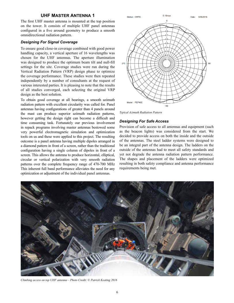
UHF Master antenna 1The first UHF master antenna is mounted at the top position on the tower. It consists of multiple UHF panel antennas configured in a five around geometry to produce a smooth omnidirectional radiation pattern.
Designing For Signal CoverageTo ensure good close-in coverage combined with good power handling capacity, a vertical aperture of 16 wavelengths was chosen for the UHF antennas. The aperture illumination was designed to produce the optimum beam tilt and null-fill settings for the site. Coverage studies were run during the Vertical Radiation Pattern (VRP) design phase to optimize the coverage performance. These studies were then repeated independently by a number of consultants at the request of various interested parties. It is pleasing to note that the results of all studies converged, each selecting the original VRP design as the best solution.To obtain good coverage at all bearings, a smooth azimuth radiation pattern with excellent circularity was called for. Panel antennas having configurations of greater than 4 panels around the mast can produce superior azimuth radiation patterns, however getting the design right can become a difficult and time consuming task. Fortunately our previous involvement in repack programs involving master antennas bestowed some very powerful electromagnetic simulation and optimization tools on us and these were applied to this project. The resulting outcome is a panel antenna having multiple dipoles arranged in a diamond pattern in front of a screen, rather than the traditional configuration having a single column of dipoles in front of a screen. This allows the antenna to produce horizontal, elliptical, circular or vertical polarization with very smooth radiation patterns over the complete frequency range of 470-700 MHz This inherent full band performance alleviates the need for any optimization or adjustment of the individual panel antennas.
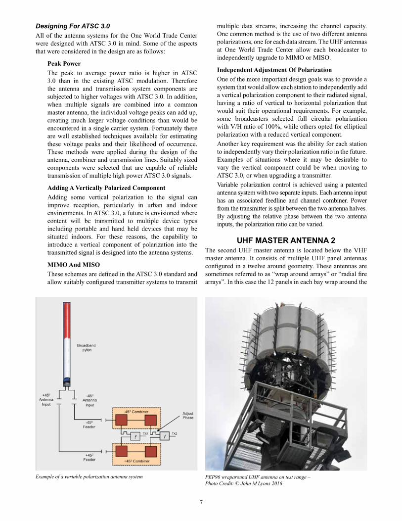
Designing For Safe AccessProvision of safe access to all antennas and equipment (such as the beacon lights) was considered from the start. We decided to provide access on both the inside and the outside of the antennas. The steel ladder systems were designed to be an integral part of the antenna design. The ladders on the outside of the antennas had to meet all safety standards and yet not degrade the antenna radiation pattern performance. The shapes and placement of the ladders were optimized resulting in both safety compliance and antenna performance requirements being met.
Climbing access on top UHF antenna – Photo Credit: © Patrick Keating 2016
Typical Azimuth Radiation Pattern
7
Designing For ATSC 3.0All of the antenna systems for the One World Trade Center were designed with ATSC 3.0 in mind. Some of the aspects that were considered in the design are as follows:
Peak Power The peak to average power ratio is higher in ATSC 3.0 than in the existing ATSC modulation. Therefore the antenna and transmission system components are subjected to higher voltages with ATSC 3.0. In addition, when multiple signals are combined into a common master antenna, the individual voltage peaks can add up, creating much larger voltage conditions than would be encountered in a single carrier system. Fortunately there are well established techniques available for estimating these voltage peaks and their likelihood of occurrence. These methods were applied during the design of the antenna, combiner and transmission lines. Suitably sized components were selected that are capable of reliable transmission of multiple high power ATSC 3.0 signals.
Adding A Vertically Polarized Component Adding some vertical polarization to the signal can improve reception, particularly in urban and indoor environments. In ATSC 3.0, a future is envisioned where content will be transmitted to multiple device types including portable and hand held devices that may be situated indoors. For these reasons, the capability to introduce a vertical component of polarization into the transmitted signal is designed into the antenna systems.
MIMO And MISOThese schemes are defined in the ATSC 3.0 standard and allow suitably configured transmitter systems to transmit
multiple data streams, increasing the channel capacity. One common method is the use of two different antenna polarizations, one for each data stream. The UHF antennas at One World Trade Center allow each broadcaster to independently upgrade to MIMO or MISO.
Independent Adjustment Of PolarizationOne of the more important design goals was to provide a system that would allow each station to independently add a vertical polarization component to their radiated signal, having a ratio of vertical to horizontal polarization that would suit their operational requirements. For example, some broadcasters selected full circular polarization with V/H ratio of 100%, while others opted for elliptical polarization with a reduced vertical component. Another key requirement was the ability for each station to independently vary their polarization ratio in the future. Examples of situations where it may be desirable to vary the vertical component could be when moving to ATSC 3.0, or when upgrading a transmitter.Variable polarization control is achieved using a patented antenna system with two separate inputs. Each antenna input has an associated feedline and channel combiner. Power from the transmitter is split between the two antenna halves. By adjusting the relative phase between the two antenna inputs, the polarization ratio can be varied.
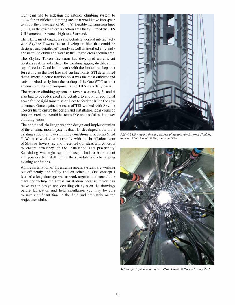
uHF Master antenna 2The second UHF master antenna is located below the VHF master antenna. It consists of multiple UHF panel antennas configured in a twelve around geometry. These antennas are sometimes referred to as “wrap around arrays” or “radial fire arrays”. In this case the 12 panels in each bay wrap around the
PEP96 wraparound UHF antenna on test range – Photo Credit: © John M Lyons 2016
Example of a variable polarization antenna system

8
antenna mast that supports the sections above. The advantage of this approach is that very smooth and predictable radiation patterns are produced having all-around coverage. All mast steel is located behind the panel antennas, and since each panel antenna has a very good front to back ratio, almost no energy is scattered from the steel structure. Contrast this to the alternative solution that involves side mounting an antenna off the side of the steel mast. With the side mounted arrangement the result is at best a directional coverage pattern and areas of poor coverage behind and to the sides of the mast. The elevation radiation pattern of UHF antenna 2 is the same as UHF antenna 1. The same type of panel antenna is used in both UHF antennas. The enhanced design provides very good performance when used in either 5 around antennas or wrap around arrays. This panel antenna, known as the PEP panel antenna has now become the standard RFS building block for high performance, multi polarization, broadband panel arrays.
Installation ConsiderationsTo simplify the installation, it was decided to pre-assemble as much of the antenna at the factory as was possible. This resulted in the antenna being shipped in 16 pre-assembled segments. Each segment consisted of 6 antenna panels with associated power splitters and distribution cables connected to the steel mounting rings. The size of these modules was dictated by the size of the freight elevator that was to transport all antenna components from the loading dock to the rooftop in preparation for lifting onto the mast.
VHF Master antennaThe high band VHF master antenna is mounted on the tower section below the first UHF antenna. It consists of 16 broadband dual polarized panels in a 4 around x 4 high configuration. The feed system comprises multiple levels of 3dB couplers, producing a very smooth and consistent radiation pattern over channels 7 through 13. Multiple antenna feeders are combined with a switching system in the combiner room to provide half antenna redundancy.
cHannel coMBInersEach antenna system has an associated channel combiner system. All combiner modules are re-tunable to any of the post repack channels. Due to the power levels involved (one transmitter is capable of over 100 kW), and in order to obtain very high efficiency, fully tunable, broadband waveguide combiner modules were selected for the UHF combiners. This high power tunable filter technology was invented in anticipation of the repack. The transmitter mask filtering is done by the combiner modules. Each broadcaster had the choice of external mask filters or filtering in the combiner and all chose to do the filtering in the combiner. The choice of 8 pole or 6 pole filter responses was also offered and each selected 8 pole responses to provide increased selectivity and future flexibility for ATSC 3.0 extended bandwidth modes.The combiner includes many recent innovations. For example, the 3dB high power couplers used in the combining modules (and also for transmitter power splitting) use new direct heat transfer technology. This ensures low operating temperatures in otherwise thermally isolated parts inside the couplers, resulting in highest TEM-mode coupler power handling while maintaining good reliability. These advanced couplers are also used in some of the high power transmitters at the site.The highest composite power exists at the final combiner module (antenna output end). This is achieved with waveguide coupler technology. However, as a departure from using classic bulky H-plane waveguide coupler technology, we designed a new compact E-plane waveguide coupler with full system frequency bandwidth and lowest insertion loss. The coupler is connected to the combiner filters using an innovative zero-loading waveguide to resonator connection, greatly simplifying the combiner filter layout.Liquid cooling is used to cool all combiner modules and test loads. Air cooling could have – in principle – been used for the combiner modules however water cooling was chosen to reduce heat load into the building.
systeM testInGEach antenna system was tested at the factory to ensure that all radiation pattern and axial ratio specifications were achieved. This involved building one quarter of each antenna on an exact full scale replica of each tower cross section. The performance was measured on one of the RFS far field antenna test ranges and found to be exactly as expected. The combiners also underwent extensive factory acceptance testing prior to dispatch to site.
Pre-assembled segments of PEP96 UHF antenna 2

9
Part 4 Tower Evaluation And Rigging– Jim Graf, Owner and Project Supervisor, Skyline Towers Inc. and
Tony Fonseca, PE, Executive Vice President, Turris Engineering Inc.
The broadcast tower initial phase began with the teaming up of Skyline Towers Inc and Turris Engineering Inc. (TEI) to conduct a tower inspection and verification of the existing conditions. Some of the tower information was not available or had to be confirmed. In a large complex construction project such as One WTC, some revisions to details and connections are not always documented. We knew that complete accuracy was required to ensure antenna components would fit properly and the design of the antenna components had to be implemented around the existing structure. Our inspection team spent several days climbing the tower structure and taking measurements of the various sections of the tower and cross sections. We had to check the existing conditions for the top UHF antenna in section 7, the top section of the tower just below the top light cone. We also checked the top of section 6 for the associated power divider mounting for the UHF antenna and the associated transmission lines and 7/8” feed lines to the power divider.
Men Working on UHF Power Divider – Photo Credit: © Tony Fonseca 2016
Crow’s Nest had to be removed to install PEP40 antenna panels – Photo Credit: © Tony Fonseca 2016
The new internal climbing system – Photo Credit: © Tony Fonseca 2016
10
Antenna feed system in the spire – Photo Credit: © Patrick Keating 2016
PEP40 UHF Antenna showing adapter plates and new External Climbing System – Photo Credit: © Tony Fonseca 2016
Our team had to redesign the interior climbing system to allow for an efficient climbing area that would take less space to allow the placement of 80 – 7/8” flexible transmission lines (T/L’s) in the existing cross section area that will feed the RFS UHF antenna - 8 panels high and 5 around.The TEI team of engineers and detailers worked interactively with Skyline Towers Inc to develop an idea that could be designed and detailed efficiently as well as installed efficiently and useful to climb and work in the limited cross section area.The Skyline Towers Inc team had developed an efficient hoisting system and utilized the existing rigging shackle at the top of section 7 and had to work with the limited rooftop area for setting up the load line and tag line hoists. STI determined that a Tractel electric traction hoist was the most efficient and safest method to rig from the rooftop of the One WTC to hoist antenna mounts and components and T/L’s on a daily basis.The interior climbing system in tower sections 4, 5, and 6 also had to be redesigned and detailed to allow for additional space for the rigid transmission lines to feed the RF to the new antennas. Once again, the team of TEI worked with Skyline Towers Inc to ensure the design and installation ideas could be implemented and would be accessible and useful to the tower climbing teams.The additional challenge was the design and implementation of the antenna mount systems that TEI developed around the existing structural tower framing conditions in sections 6 and 5. We also worked concurrently with the installation team of Skyline Towers Inc and presented our ideas and concepts to ensure efficiency of the installation and practicality. Scheduling was tight so all concepts had to be efficient and possible to install within the schedule and challenging existing conditions.All the installation of the antenna mount systems are working out efficiently and safely and on schedule. One concept I learned a long time ago was to work together and consult the team conducting the actual installation because if you can make minor design and detailing changes on the drawings before fabrication and field installation you may be able to save significant time in the field and ultimately on the project schedule.