on wood floor systems
TRANSCRIPT

INFLUENCE OF SHEATHING GAPS ON WOOD FLOOR SYSTEMS
Rajk Y. Itani Associate Professor
Department of Civil and Environmental Engineering Wa\hington State University, Pullman, WA 99164
(Received 18 March 1982)
ABSTRACT
This paper describes a comparative study of the partial composite action of wood floors with and without sheathing gaps. The beams investigated consist of plywood sheathing bonded to joists with elastomeric adhesive. Beams are considered to be simply supported and subjected to uniformly dis- tributed loading. Results for continuous sheathing, open gaps at third and fourth points are compared and displayed graphically.
It is shown that the influence of gaps on the partial composite action is drastic and can increase deflections by as much as 8?'+, compared to a system with continuous sheathing. Little difference is obtained when comparing a heam with gaps at third and fourth points.
k'r?lt.ords: Beams. compos~te structures, construction materials, deflection, deformation, fastener\. floors, joists. loads (forces). mechanics, moments, plywood, stresses.
INTRODUCTION
Partial composite interaction between sheathing and joists enhances the rigidity and strength of floors. Such an interaction is usually generated by the use of various glue and mechanical connectors between the sheathing and joists.
Open gaps between the sheathing tend to interrupt the partial composite action and significantly influence the behavior of floors. This is of importance since the composite action is counted on to bring deflections and stresses to within code specification.
While there have been several studies regarding the influence of open gaps on floor behavior, the intent of this paper is to provide a comparative study of the behavior of floors with continuous sheathing and with open gaps at third and fourth points of the span length. Such a comparative study is of importance to engineers since it clearly illustrates the significance of these gaps.
This study concentrates on the use of elastomeric adhesives that are capable of imparting composite action and that are suitable for field use over a broad range of curing conditions using only nail pressure. It will be shown that, with minor modifications, the theory presented here is also applicable to mechanical connectors such as nails.
This paper is based on previous studies presented by ltani and Brito (1978) and by Anderson ( 1975). The accuracy and formulation of these studies are discussed in detail in the references indicated. A brief summary of pertinent literature and of the formulation is given in this paper.
Notations
The following symbols are used in this paper: b = width of glue line; C, , C, =
constants; c , , c, = distances from neutral axis to extreme fibers; F = axial force
b+',~O<l ,!,!<I k!Il<,l 5 < , ? t , < t,, l5(3) . 19x3. pp , 1x1-202 I ) I % ? by the Soc~ety of Wood S c i c n ~ e ;ind l'echnolopy

I~(IIII-SHEATHING GAPS ON WOOD FI.OORS 1 91
in layers; L = span length of beam; M, = moment due to applied loads at dis- tance of x from origin; M,, M, = moments in layers one and two, respectively; P,, P3, P4, Q,, R,, R3, R I = constants; w = load per linear measurement; y = de- flection; z = sum of c , and c,; 0 = slope; and T = shear stress.
BACKGROUND
The layered beam system has been a topic of research for a number of investi- gators. In 1949, Granholm presented a study on the composite behavior of lumber beams and columns, while Newmark, Seiss, and Viest (1951) investigated incom- plete interactions between a concrete flange and a steel T-beam. Interlayer slip in wooden structures was covered by Pleshkov (1952), while Goodman ( 1967) concluded that even though the initial approaches of the previously mentioned investigators were different, the theories, as well as the assumptions on which the theories were based, were in agreement.
From 1967-1974, Goodman et al. (Goodman 1969; Goodman and Popov 1968; Goodman et al. 1974) developed expressions for laminated beams, two-way joist floor system plates, and shells. In these studies, individual shear connectors were assumed to be replaced by continuous shear connectors. Supporting experimental studies showed agreement between computed and test results. Rose (1969) showed experimentally the marked effect of unspliced panel joints on the stresses and deflections of such systems.
McGee and Hoyle (1974) utilized the work of Newmark et al. (195 I) in obtaining design equations for ;I two-layer system continuously glued with elastomeric ad- hesives. Anderson (1975) extended the work of McGee and Hoyle to account for three-layer systems.
In 1975, Thompson. Goodman, and Vanderbilt developed a finite element mod- el for multilayered systems. Their solutions accounted for varying material prop- erties, as well a.; discontinuities, in any layer of the system. The measured and computed results showed close agreement for the cases considered. This study was extended by Trernblay, Goodman, and Criswell (1976) to account for non- linear material behavior.
McCutcheon (1977') presented a study for predicting the stiffness of wood floor systems with partial composite action and sheathing discontinuities. Bessette (1977) presented a thesis in which he experimentally evaluated the effects of open gaps on T-beams bonded with elastomeric adhesives. Itani and Brito (1978) cle- veloped a theoretical study for computing stresses and deflections in floors with gaps. The study was done concurrently with that of McCutcheon (1977), and results compared favorably. The theoretical results were also compared w ~ t h the experimental results presented by Bessette (1977).
Sazinski and Vanderbilt (1979) presented a study on the behavior and design of wood joist floors. In that study the authors introduced three new design meth- ods of wood joist and sheathing floors subjected to static loading. Gaps resulting from loosely butted sheets are considered, using a n~athematical finite element approach. The influence of the interaction between any two adjacent sheets on the floor behavior is studied by varying the elastic properties of the element representing the gap.
The shear modulus of elastomeric adhesives ranges from around 50 psi-9.000 psi, while the shear modulus for wood is about 130,000 psi (Douglas-fir longitu-
192 WOOI) A N D FIBER SCIENCE. JULY 1983, V . l%i)
dinal plane (Gillespie 1972). This means that these adhesives may be capable of providing only partial interaction between built-up pieces because the adhesives are less rigid than the components. Studies made with the available range of products indicate that some of these do meet the criteria for strength and stiffness to perform adequately during the service life of the joist-deck structures (Vick 1971). The creep of elastomeric glue lines considerably exceeds wood creep: however, Hoyle (1976) indicated that this did not present a serious structural problem. Tests have shown that structural members with elastomeric adhesive glue lines (g = 50 psi-100 psi) can develop up to 80% of the improvement that rigid joints produce over noncomposite behavior.
Design computations for wood structural systems bonded with elastomeric ad- hesives are more complex than for systems using common laminating adhesives. The elastomeric adhesives are more compliant than the phenol-resorcinol adhe- sives used in making laminated wood beams and lumber-plywood stressed skin panels. They permit a measure of slip between the parts that must be accounted for in the design.
Kuenzi and Wilkinson ( I97 I), Goodman (1 969), Tremblay et al. ( 1976), McGee and Hoyle (1974), and Anderson (1975) have addressed the problem of executing these types of design. The design equations are generally too complex for day- to-day use in routine design work but can form the basis for simple design meth- ods. Hoyle and Anderson (1975) employed these procedures to generate curves for modifying the statical moment and moment of inertia of common plywood sheathed wood roof and floor systems with continuous panels.
A detailed description of other literature is presented in Brito (1977).
As indicated earlier, the study presented here is based on the theory presented in references of Anderson (1977) and Itani and Brito (1978). This theory has been experimentally verified in these references. A brief description of the formulat~orl is given here.
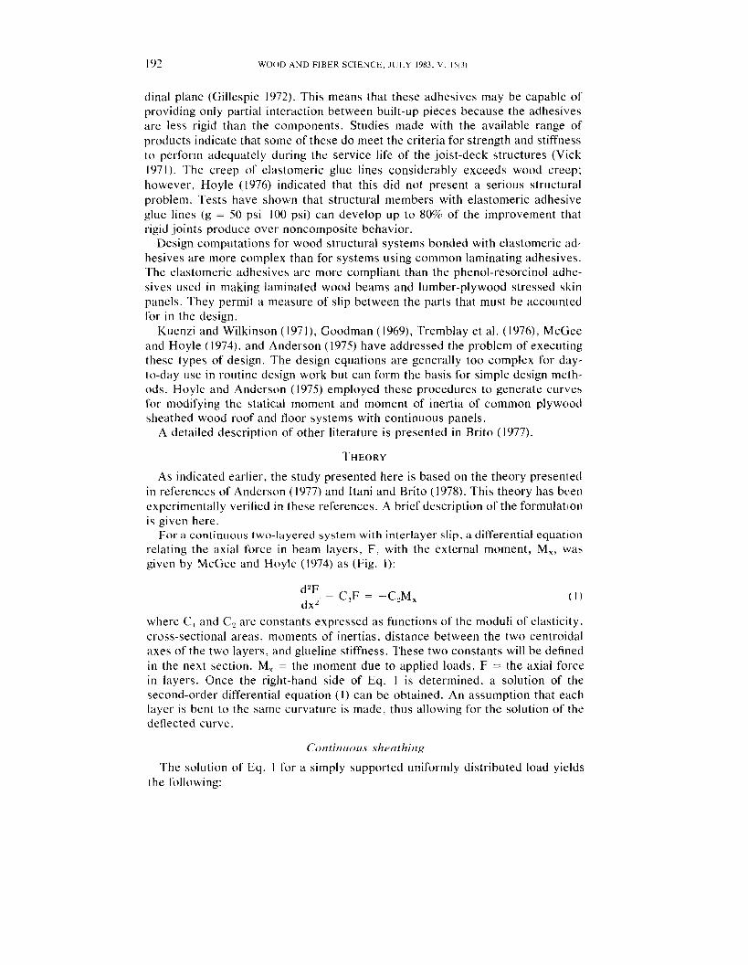
For a continuous two-layered system with interlayer slip, a differential equat~on relating the axial force in beam layers, F, with the external moment, M,, was given by McGee and Hoyle (1974) as (Fig. I):
d2F - - C,F = -C2M, dx"
where C , and C, are constants expressed as functions of the moduli of elasticity. cross-sectional areas, moments of inertias, distance between the two centroidal axes of the two layers, and glueline stiffness. These two constants will be defined in the next section. M, = the moment due to applied loads, F = the axial force in layers. Once the right-hand side of Eq. 1 is determined, a solution of the second-order differential equation ( I ) can be obtained. An assumption that each layer is bent to the same curvature is made, thus allowing for the solution of the deflected curve.
Continrio~is sheathing
The solution of Eq. I for a simply supported uniformly distributed load yields the following:

ltrrrrr-SHEATHING GAPS ON WOOD FLOORS
CENTROIDAL AXlS
if
CENTROIDAL AXlS LAYER TWO F --- dF F+ -da -- -
d x
d x d V , v + - d x
d a da ( b ! CROSS SECTION
(a) BEAM ELEMENT
CENTROIDAL AXIS
CENTROIDAL AXlS
NO INTERACTION INCOMPLETE INTERACTION COMPLETE INTERACTION
( C ) STRAIN DISTRIBUTION
FIG. I . T-beam with varying degrees of composite action
For deflection, the following equation is obtained:
Fz wx Y = -- --- + -- -- - (x" 2x2L + L3) ( 3 ' )
(El11 + E ~ I ~ ) C I (EIIl + E212) + -"--) E l E I E,A, +
where w = load intensity x = distance from the left support
L, = length of the beam y = deflection
E , , EL = moduli of ela5ticity of layers I and 2 I,, 1, = moments of inertia of layers 1 and 2 about their centroidal axe5
A , , A, = cros-sectional areas of layers 1 and 2 z = distance between centroidal axes of the two layers (Fig. I ) -
EI
C2 = S= (El11 + E212)
S = glueline stiffness and is a function of the modulus of rigidity G ,
thickness t , and width b, of the glueline S = -- 3

1 94 WOOD A N D FIBER SCIENCE. J U L Y 1983, V . 15(3)
PLAN
w Ibs./ f t
ELEVATION END VIEW
FIG. 2. Beam with flange gaps at third points.
Shruthirzg discontinuitirs
Discontinuitv a t third points.-This case is shown in Fig. 2. The beam is mod- eled (Fig. 3) into three segments: AB, BC, and CD. The mid-span deflection of beam AD is given by (Figs. 3b and 3c):
Solution of Eq. 1 for each of the beams AB and BC will yield the force F ;mtl consequently the deflected curve can be determined. The mid-span deflection is found to be:
where
wc , Ql 1 --
2C I
Discontinrlitic~s oj f'orirth point.-This case is shown in Fig. 4. The analys~s of such a beam is shown in Fig. 5 . T h e model used t o obtain the midspan deflection is shown in Figs. 5b and 5c. The equation for midspan deflection is:

Itlrt~r-SHEATHING GAPS O N WOOD FLOORS 19.5
1 Y Y r-' Y
a ) Free Body Diagrams
Y MIDPOINT
b) Deflected Beam
c) Three "~quivalent" Beams
FIG. 3 Analysis of beam with flange gaps at third points.
p:FE:E[EG! PLAN
L /4 1 L / 4 1
ELEVATION END VIEW
FIG. 4. Beam with gaps at fourth points.

WOOD A N D FIBER SCIENCE. JULY 1983. V . 15(3)
Y Y Y Y
a) Free Body Diagrams
b) De f lec ted B e a m
c) Four ' ' ~ ~ u i v a l e n t " Beams
FIG. 5 . Analysis of beam with gaps at fourth points.
where

Itoni-SHEATHING GAPS ON WOOD FLOORS
700r JOIST: 2 x 6
FLANGE 5/16 x 24 m LOAD 8 33 Ibs / In
NO FLANGE- -
7 5 p s 1 (3)-
\
( NO GAPS )
, -G = 7 5 psl
- 1 0 5 PSI
r10 ,ooo PSI
( 3 ) - GAPS AT THIRD POINTS
( 4 ) - GAPS AT F O U R T H POINTS
0 --
144 168 192 216
SPAN ( i n ) FIG. 6. Midspan deflection versus span for different glueline rigidity and 2 x 6 joist.
M~chanica l connectors
Should the glue be replaced by a mechanical connector system, the glueline stiffness S, appearing in the constants C, and C, of Eqs. I through 6 would have to be replaced by its equivalent for the mechanical connector system. In that case. the stiffness of the mechanical connectors, p, would be given by:
where
k = slip modulus of the connectors in Iblin. n = number of connectors per row d = spacing of connectors in inches along the joist length
The shear stress in the adhesive is obtained as:

WOOD .4ND FIHEK SCIENCE, JULY 1983, V. l i ( 3 )
NO FLANGE - - G - 7 5 p s 1 ( 4 ) \
105 psi ( 4 ) - -, 7 5 psi (31- -
105 psi 131
JOIST 2 x 8
FLANGE 3/4 x 2 4 1 " LOAD 8 3 3 l b s / i n
( 3 ) - GAPS AT THIRD POINTS ( 4 - GAPS AT FOURTH POINTS
SPAN ( i n )
FIG. 7. Midspan deflection versus span for different glueline rigidity and 2 x 8 joist.
where b = width of gll~eline. Flexural stresses are determined using the theory of flexure.
'Taking compressive forces as negative, the stresses in the extreme fibers of each layer, due to an axial force and bending moment, are written as
in which a,, = the stress in the topmost fibers of the ith layer (i = 1, 2); and u,,, = the stress in the lowest fibers of the ith layer. Compressive stresses are considered to be negat~ve, while tensile stresses are taken to be positive.
RESULTS
Using the methods presented in this paper, the stresses and midspan deflections were calculated for a variety of T-beams. The beams investigated had spans varying from I:! to 18 feet and had a uniformly distributed load of 100 Ib per l~neal foot. The flange width was 24 inches. Three different thicknesses of plywooti sheathing were used: 5'16, ' 1 2 , and 3/4 inch. Joist sizes of 2 x 6 and 2 x 8 inches were used. The modulus of elasticity was 1,980,000 pounds per square inch for the effective area of the plywood and 1,540,000 pounds per square inch for the joists. The glueline thickness was held constant at 0.05 inch for all the beams;

I/(III~-SHEA'I'HING GAPS ON WOOD FLOORS
JOIST 2 x 6 & 2 x 8 FLANGE. 5/16 x 2 4 in LOAD. 8.33 Ibs/in
GLUE LINE RIGIDITY' 75 pd LINE RIGIDITY' 75 pd
2 x 6 (3)-,
- - - - 2 x 8 ( N O GAPS)
( 3 ) - GAPS AT THIRD POINTS
L ( 4 ) - GAPS AT FOLIRTH POINTS
0 144 168 192 216
SPAN ( i n 1 FIG. 8. Midapan deflection veraus span for different joists.
the glueline width was equal to the width of the joist, and the modulus of rigidlty of the glueline was varied from 75 pounds per square inch to 105 pounds per square inch, which is the usual variation range for one glue. By varying all these factors, bending stres\es and midspan deflection were computed for beams w ~ t h continuous flange, flange discontinuities at third points and at fourth points. Beams with rigid connections and continuous flanges were also analyzed, to serve as reference points. In addition, solutions of deflections are compared to b e a m without sheathing.
Figures 6 and 7 show the midspan deflection versus span for different glueline rigidities and sections. The mispan deflection of beams with gaps at third points was in the range of 49 to 69% larger than the midspan deflection of beams w ~ t h no gaps. The same comparison between beams with no gaps and beams with gaps at fourth points gave results of 54 to 82%. The lower percent limit was for shorter spans. The midspan deflection of the beam with gaps at third points was in the range 93 to 97% of the midspan deflection of beams with gaps at fourth points. These results showed that the midspan deflection increases significantly by the presence of few gaps. However. deflections of beams with gaps at third and fourth points showed no significant difference.

WOOD A N D FIBER SCIENCE, J U L Y 1983, V. 1 3 3 )
5/16 ( 4 )--\
JOIST 2x 6
FLANGE '116, '12 B 3/4 x 24 LOAD 8 3 3 Ibs/ ln
GLUE LINE RIGIDITY 75 psi
( 3 ) - GAPS AT THIRD POINTS
I (4) - GAPS AT FOURTH POINTS
,i 144 168 192 216
SPAN ( i n )
FIG. 9. Midspan deflection versus span for different flange thicknesses.
One can infer- from these results that the longer the span is, the smaller is the relative difference in midspan deflections both between the beam system without gaps and the beam system with gaps at third and fourth points. As reference points in Figs. 6 and 7, the midspan deflections of a beam with rigid connection and no flange discontinuities and of a beam with no flange were drawn in. To simulate rigid connection, the glueline rigidity was set equal to 10,000 pounds per square inch.
Figure 8 shows the midspan deflection versus the span for two different joist sizes. Beams with 2- x 8-inch joists had a midspan deflection in the range 43 to 50% of that for beams with 2- x 6-inch joists. The lower percent limit was for beams with continuous flange. This was the same relation between beams with no gaps, beams with gaps at third points, and beams with gaps at fourth points both for 6-inch and 8-inch joists. One should note that a beam with 2- x 8-inch joist and gaps at fourth points has smaller midspan deflections than a beam with 2- x 6-inch joist with no gaps.
Figure 9 shows the deflection versus the span for different sheathing thick- nesses. The midspan deflection of beams with '12-inch flange was in the range 90 to 99% of the midspan deflection of the beams with S/~6-inch flange. The corre-

II(JII~-SHEATHING GAPS O N WOOD FLOORS
JOIST: 2 x 6
FLANGE : 5/16 x 2 4
LOAD 8 3 3 I b s / i n
LENGTH : 144 In
GLUE L lNE RIGIDITY. 75 psi NO GAPS' GAPS AT THIRD POINTS
JOIST. 2 x 8
FLANGE 3/4 x 24
LOAD: 8 3 3 Ibs / in
LENGTH : 216 in
GLUE L l N E RIGIDITY ' 105 psi
NO GAPS. GAPS AT THIRD POINTS
FIG. 10. Stress distribution ovel. the section at the midpoint.
sponding percentage for beams with 3/4-inch flange was 82 to 97. The lower per- cent limit was for the beams with no flange discontinuities. The difference in midspan deflection between beams with different flange thicknesses is very small, and little is gained by increasing the flange thickness. Increase in flange thickness does not compensate for frequent flange gaps.
The effect of gaps on stresses is studied by the movement of the neutral axis. Figure 10 shows the stress distribution over the section for two beams. Initially with no gaps, the flange is mainly in compression, and the entire system is bending around a single neutral axis, which is shown by a dotted line for each of the beams in Fig. 10. With the introduction of gaps, a "two-beam" effect starts developing as the flange and joist start bending around their own neutral axes. The new location of the joist neutral axis as shown in the figure is considerably lower than of the beam without flange gaps.
CONCLUSIONS
It is concluded that sheathing discontinuities have a considerable effect on beam performance, and deflections increase drastically with their presence. In- creasing joist depth or flange thickness has little effect on the relationship between a discontinuous and a continuous floor system. It is also concluded that small
202 WOOD A N D FIBER SCIENCF, JULY 1983, V l5(3)
improvement in floor behavior is obtained by increasing the thickness of sheath- ing. Introduction of open gaps interrupts the partial composite action and has significant effects on stress distribution. With open gaps, redistribution of stresses in sheathing and joist occurs, causing a shift in their neutral axes.
REFERENCES
ANDF.RSON. M . A. 1975. Behavior of wood beams with an elastomeric adhesive. M.S. thesi\, Washington State Univel-sity, Pullman. WA.
BESSETTE, A. 1977. An evaluation of elastomeric adhesive bonded design theory and the effect of panel gaps in T-beams. M.S. thesis, Washington State University, Pullman, WA.
BRI I 0. F. 1977. Investigation of the elastomeric adhesive bonded wood T-beam having gaps in the flange. M.S. Thesis. Wa\hington State University, Pullman, WA.
G I L I E S P I ~ . R . H. 1972. Elastomeric adhesives in building construction. Building Research, Oct.1 Dec.
GOODMAN, J. R. 1967. Layered wood systems with interlayer slip. Ph.D. thesis, University of California, Berkeley. CA.
1969. Layered systems with interlayer slip. Wood Sci. 1(3):148-158. ---. A N D E. P. Popov 1968. Layered beam systems with interlayer slip. Struct. Div., ASC'E
Proc. Paper 62 14, 94(ST I 1):2535-2547. . ET AL. 1974. Composite and two-way action in wood joist Roor systems. Wood Sci. 7(1 I :
25-33. G K \ N H O I M, H . 1949. On1 sammansatta balkar och pelare med 5arskild hansyn till spikade
trakonstruktioner (On composite beams and columns with particular regard to nailed t i~nhel structures). Chalmers Tekniska Hogskolas Handlingar, No. 88.
H O Y L ~ , R. J . . JR . 1972. Wood technology in the design of structures, 2nd ed. Washington State University. Pullman, WA.
. 1973. Behavior of wood I-beams bonded with elastomeric adhesive. College of Engineering, Research Ilivision Bulletin 328. Washington State University, Pullman, WA.
-. 1976. Designing wood structures bonded with elastomeric adhesives. For. Prod. 1. 16(3): 28-34.
. A N I ) M. A. ANDERSON. 1975. Performance predictions for elastomeric adhesive bonded wood structural system\. College of Engineering. Research Report 75157-2, Washington St;ttc. University, Pullman. W.4.
I I A N I . R. Y . , A N D F. A. BRITO. 1978. Elastomeric bonded wood beams with transverse gaps. 1 . Str. Div. ASCE Proc. Paper 14095, 104(ST10): 1595-1609.
KUENZI . E. W., A N D T. 1.. WILKINSON. 1971. Composite beams-effect of adhesive on fastenel. rigidity. USDA Forest Service Research Paper FPL- 152.
MCCUTC'HEON. W. J . 1977 Method for predicting the stiffness of wood-joist floor systems with partial composite action. USDA Research Paper FPL-289.
MCGEE. D. W . , A N D R. J . HOYLE, JR. 1974. Design method for elastomeric adhesive bonded wood joist deck systems. Wood Fiber 6(?): 144-155.
NEWMARK. N. M. . C. P. S I ISS. A N D I . M. VEIST. 1951. Tests and analyses of composite bean],< with incomplete interac~ion. Proceedings, Society for Stress Analysis IY(I).
PLESHKOV. P. F. 1952. l eor i ia rascheta depeviannykh (Theoretical studies of composite wood structures). Moscow, USSR.
ROSE, J . D. 1969. Field glued plywood floor test. American Plywood Association Labor.ltorp, Report 118.
S A L I N S K I , R. J.. A N D M. D VANDERBILT. 1979. Behavior and design of wood joist floors. Wood Sci. 11(4):209-220.
T H ~ M I ~ S O N . E. G.. 1. R. GOODMAN, A N D M. D. VANDERBILT. 1975. Finite element analqsis cisf wood layered systems. ASCE IOI(STI2):2659-2672.
'I'RL-.MBLAY, G. A , , J . R. GOODMAN. A N D M. E. CRISWEI-L. 1976. Non-linear analysis of layered T-beams with interlayer slip. Wood Sci. 9(1):21-30.
V ~ N D ~ R B I I . T , M. I)., J . R. GOODMAN, A N D M. E. C R I S W ~ I . L . 1974. Service and over-load behavior of wood joist floors systems. ASCE Proc. Paper 10274, IOO(ST1): 11-29.
VICK. C. B. 1971. Elastonieric adhesive5 for field gluing plywood floors. Prod. J . 21(8):344!.