on the way to ilc shekhar mishra fermilab talk presented on behalf of ilc-gde 2/16/06 talk presented...
TRANSCRIPT
On the Way to ILC
Shekhar MishraFermilab
Talk presented on behalf of ILC-GDE2/16/06
Talk Presented at the 2006 Aspen Winter Conference: "Particle Physics at the Verge of Discovery"
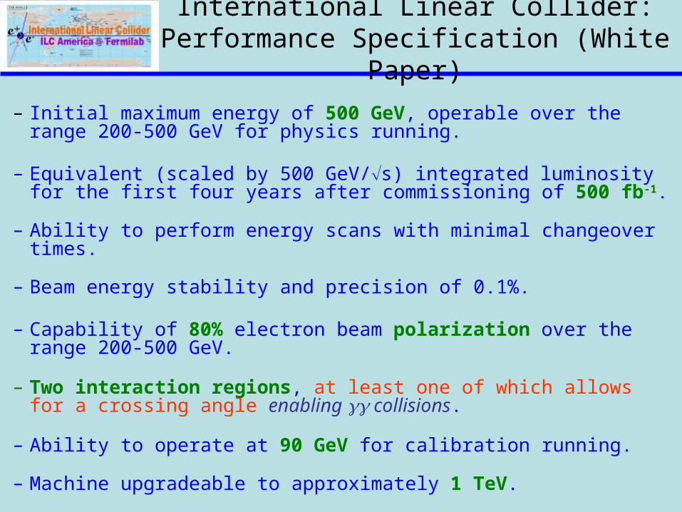
International Linear Collider: Performance Specification (White Paper)
– Initial maximum energy of 500 GeV, operable over the range 200-500 GeV for physics running.
– Equivalent (scaled by 500 GeV/s) integrated luminosity for the first four years after commissioning of 500 fb-1.
– Ability to perform energy scans with minimal changeover times.
– Beam energy stability and precision of 0.1%.
– Capability of 80% electron beam polarization over the range 200-500 GeV.
– Two interaction regions, at least one of which allows for a crossing angle enabling collisions.
– Ability to operate at 90 GeV for calibration running.
– Machine upgradeable to approximately 1 TeV.

Road to: Reference Design Report
• 1st ILC Workshop at KEK (11/2004)– working groups (WG) formed to begin identifying contentious design
issues
• 2nd ILC Workshop Snowmass (8/2005)– modified WG continue identifying baseline design and alternatives– newly formed ‘Global Groups’ begin to discuss and catalogue global
design issues– 2nd Snowmass week: concentrate on the list of ‘Top 40’ critical design
questions
• 1st Meeting of the ILC-GDE (12/2005)– Acceptance of the Baseline Configuration Document (BCD)– Start work towards the Reference Design Report (12/2006, with Cost)– Formation of Accelerator System, Technology and Global systems– Formation of
• Design and Cost Board, Change Control Board and R&D Board
ITRP Recommendation (Aug 2004) : Superconducting RF is accelerating technology for ILC
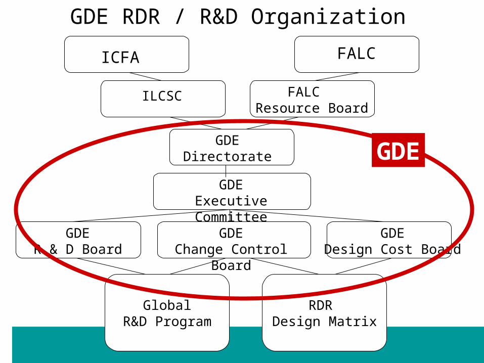
ICFA FALC
FALC Resource Board
ILCSC
GDEDirectorate
GDEExecutive Committee
GlobalR&D Program
RDR Design Matrix
GDER & D Board
GDEChange Control Board
GDEDesign Cost Board
GDE RDR / R&D Organization
GDE
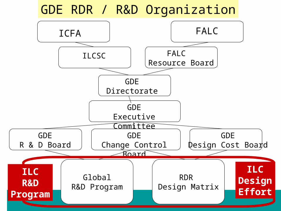
ICFA FALC
FALC Resource Board
ILCSC
GDEDirectorate
GDEExecutive Committee
GlobalR&D Program
RDR Design Matrix
GDER & D Board
GDEChange Control Board
GDEDesign Cost Board
GDE RDR / R&D Organization
ILCDesignEffort
ILCR&D
Program

Mission of Global Design Effort
• Produce a design for the ILC that includes – A detailed design concept – Performance assessments – Reliable international costing – An industrialization plan– Siting analysis– Detector concepts and scope
• Coordinate worldwide prioritized proposal driven R & D efforts – To demonstrate and improve the performance– Reduce the costs– Attain the required reliability, etc.

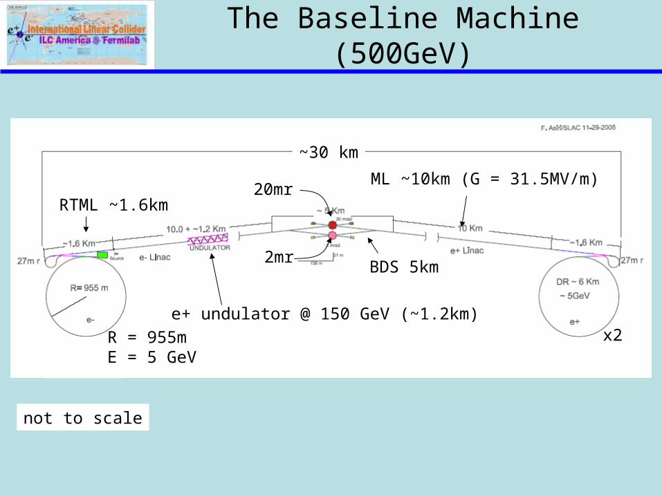
The Baseline Machine (500GeV)
not to scale
~30 km
e+ undulator @ 150 GeV (~1.2km)x2R = 955m
E = 5 GeV
RTML ~1.6km
ML ~10km (G = 31.5MV/m)20mr
2mrBDS 5km
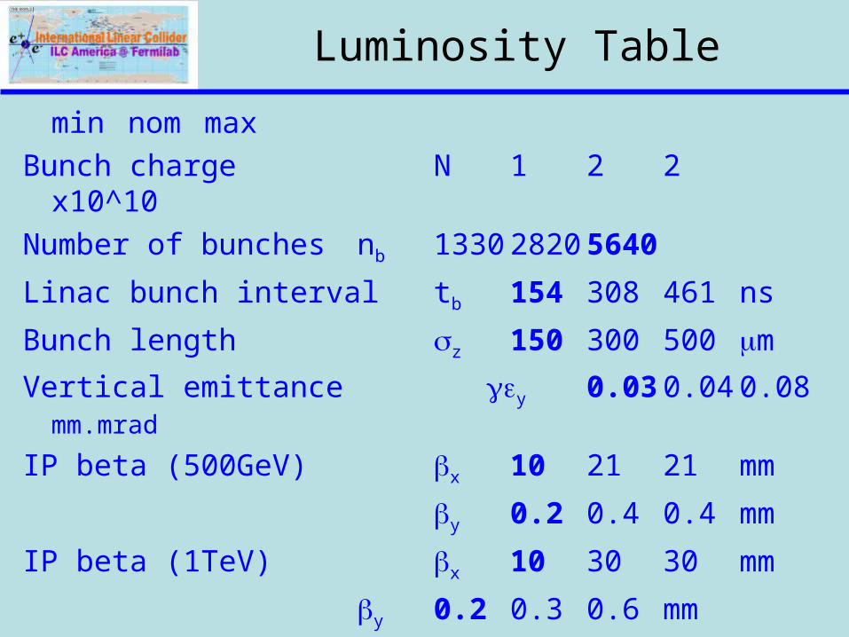
Luminosity Table
min nom max
Bunch charge N 1 2 2 x10^10
Number of bunches nb 1330 2820 5640
Linac bunch interval tb 154 308 461 ns
Bunch length z 150 300 500 m
Vertical emittance y 0.03 0.04 0.08 mm.mrad
IP beta (500GeV) x 10 21 21 mm
y 0.2 0.4 0.4 mm
IP beta (1TeV) x 10 30 30 mm
y 0.2 0.3 0.6 mm

Baseline Electron Source
Positron-style room-temperature
accelerating section
diagnostics section
standard ILC SCRF modules
sub-harmonic bunchers + solenoids
laser E=70-100 MeV
• DC Guns incorporating photocathode illuminated by a Ti: Sapphire drive laser.
• Long electron microbunches (~2 ns) are bunched in a bunching section
• Accelerated in a room temperature linac to about 100 MeV and SRF linac to 5 GeV.
DC gun(s)
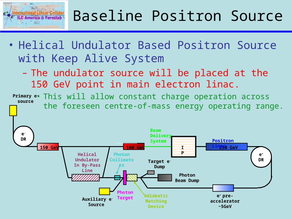
Baseline Positron Source
• Helical Undulator Based Positron Source with Keep Alive System– The undulator source will be placed at the 150 GeV point
in main electron linac. • This will allow constant charge operation across the foreseen
centre-of-mass energy operating range.
Primary e-
source
e-
DR
Target e- Dump
Photon Beam Dump
e+
DR
Auxiliary e- Source
Photon Collimators
Adiabatic Matching
Device
e+ pre-accelerator
~5GeV
150 GeV 100 GeV
HelicalUndulatorIn By-Pass
Line
PhotonTarget
250 GeV
Positron Linac
IP
Beam Delivery System
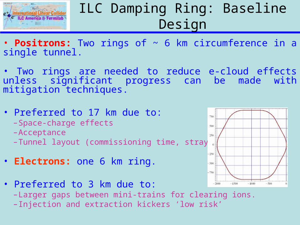
ILC Damping Ring: Baseline Design
• Positrons: Two rings of ~ 6 km circumference in a single tunnel.
• Two rings are needed to reduce e-cloud effects unless significant progress can be made with mitigation techniques. • Preferred to 17 km due to:
–Space-charge effects –Acceptance –Tunnel layout (commissioning time, stray fields)
• Electrons: one 6 km ring.
• Preferred to 3 km due to:–Larger gaps between mini-trains for clearing ions. –Injection and extraction kickers ‘low risk’

Main Linac: Baseline RF Unit

SRF Cavity Gradient
Cavity type
Qualifiedgradient
Operational gradient
Length* energy
MV/m MV/m Km GeV
initial TESLA 35 31.5 10.6 250
upgrade LL 40 36.0 +9.3 500
* assuming 75% fill factor
Total length of one 500 GeV linac 20km

Baseline ILC Cryomodule
• The baseline ILC Cryomodule will have 8 9-Cell cavities per cryomodule. The quadrupole will be at the center in the baseline design.
• Every 4th cryomodule in the linac would include a quadrupole with a corrector and BPM package.
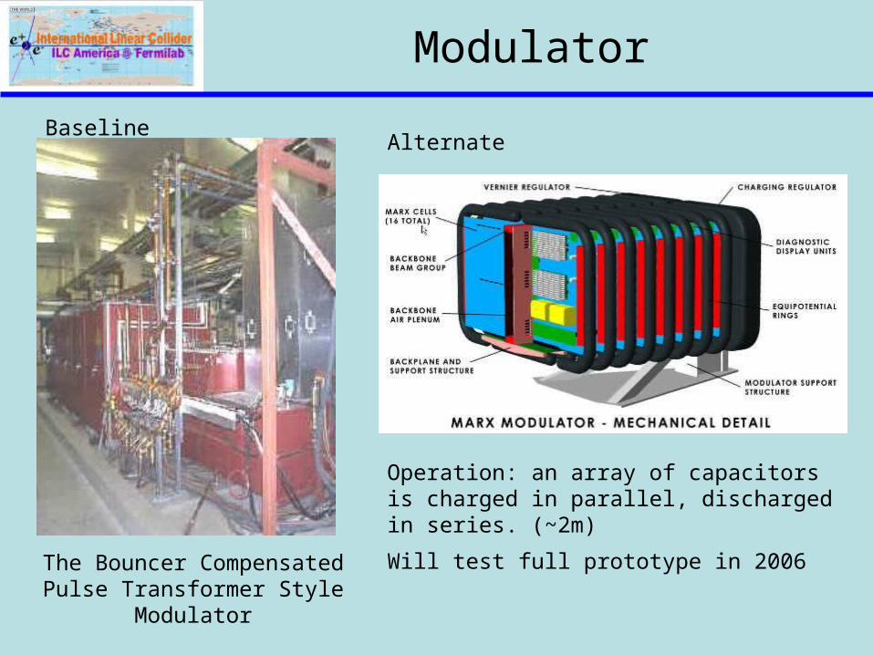
Modulator
BaselineAlternate
The Bouncer Compensated Pulse Transformer Style
Modulator
Operation: an array of capacitors is charged in parallel, discharged in series. (~2m)
Will test full prototype in 2006
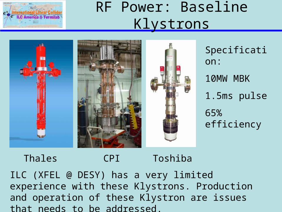
RF Power: Baseline Klystrons
Thales CPI Toshiba
Specification:
10MW MBK
1.5ms pulse
65% efficiency
ILC (XFEL @ DESY) has a very limited experience with these Klystrons. Production and operation of these Klystron are issues that needs to be addressed.

Beam Delivery System: Baseline & Alternatives
• Baseline (supported, at the moment, by GDE exec)– two BDSs, 20/2mrad, 2 detectors, 2 longitudinally separated IR
halls• Alternative 1
– two BDSs, 20/2mrad, 2 detectors in single IR hall @ Z=0• Alternative 2
– single IR/BDS, collider hall long enough for two push-pull detectors
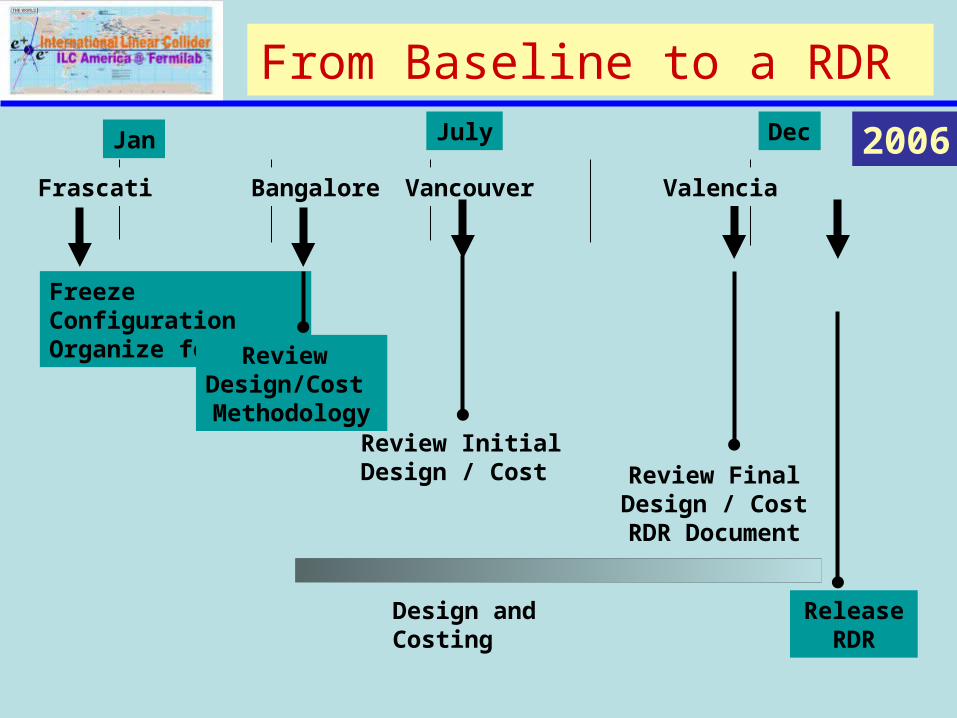
From Baseline to a RDR
Jan July Dec 2006
Freeze ConfigurationOrganize for RDR
Bangalore
Review Design/Cost Methodology
Review InitialDesign / Cost Review Final
Design / CostRDR Document
Design and Costing ReleaseRDR
Frascati Vancouver Valencia

ILC R&D
• Major laboratories around the world are working on the ILC Accelerator R&D.– Europe
• DESY (TESLA) (55 Institutions)• European XFEL• CARE (11 Institutions)• EuroTeV (27 Institutions)• UK-LCABD (15 Institutions)
– Americas (9 Laboratories and Universities)• Fermilab• SLAC
– Asia (6 Institution in 5 countries)• KEK
Some Highlights of R&D Activities

Key Issues: ILC Main Linac Accelerator Technology
• The feasibility demonstration for the ILC requires that a cryomodule be assembled and tested at the design gradient of 35 MV/m.
– Cavity technology development to routinely achieve > 35 MV/m and Q ~0.5-1e10,
• Finalize the design of an RF Unit and evaluate the reliability issues. It is important to fully test the basic building block of the Linac.
• High Power Coupler, HOM, Tuner etc.
• 10 MWatt Multi-Beam Klystron, Fabrication, Operation and reliability
• RF Distribution, Controls and LLRF
• Instrumentation and Feedback
• Quadrupole, Corrector and Instrumentation package
• Cryogenic Distribution

Europe: ILC R&D
• DESY is leading the ILC R&D in Europe. The XFEL at DESY uses ILC Technology and have common R&D goals.– Cavity Gradient– Industrial studies and development of Main Linac
Components.
• Coupler• RF Power• Cryogenics (LHC)• Instrumentation• Beam Delivery System

DESY: ILC Accelerator Modules in Operation
At present DESY is operating modules 2* ACC1 Febr 041* ACC2 June 023* ACC3 April 03 4 ACC4 April 035 ACC5 April 03
In single cavity measurements
6 out of 8 cavities reach 30 MV/m!
ACC5
LaserBunch
Compressorbypass
UndulatorsCollimator
Bunch Compresso
r
RF gun
5 MeV 127 MeV 370 MeV 445 MeV
Accelerating StructuresDiagnostics
FEL diagnostics
250 m

ILC R&D at Fermilab
• ILC R&D effort at Fermilab is focused on key design & technical issues in support of the RDR, cost estimate and eventually the CDR for the ILC.
• We also have the goal of positioning the Americas to host the ILC at Fermilab
• Our efforts are focused on two main areas of the ILC– Main Linac Design– Civil and Site Development
• Main Linac R&D:– The goals are to demonstrate the feasibility of all Main Linac technical
components, develop engineering designs, estimate costs, explore cost reduction, and engage US industry
• Civil and Site Development– Fermilab is working with the GDE and international partners to develop a matrix
for comparing possible ILC sites– We also work to develop U.S. sites on or near Fermilab
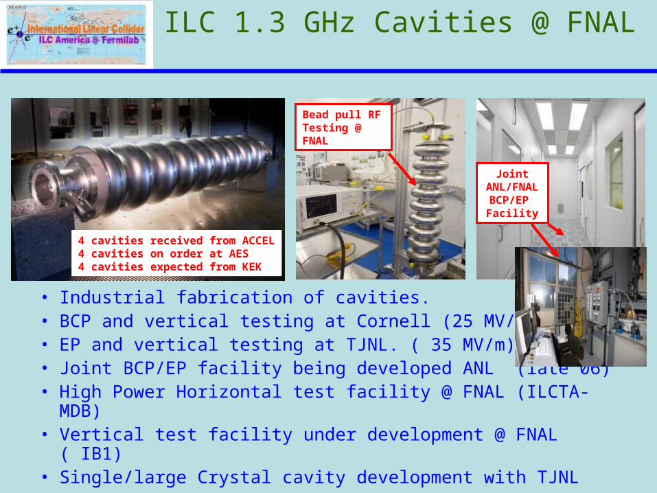
ILC 1.3 GHz Cavities @ FNAL
• Industrial fabrication of cavities.• BCP and vertical testing at Cornell (25 MV/m)• EP and vertical testing at TJNL. ( 35 MV/m)• Joint BCP/EP facility being developed ANL (late 06)• High Power Horizontal test facility @ FNAL (ILCTA-MDB)• Vertical test facility under development @ FNAL ( IB1)• Single/large Crystal cavity development with TJNL
4 cavities received from ACCEL4 cavities on order at AES4 cavities expected from KEK
Bead pull RF Testing @ FNAL
Joint ANL/FNALBCP/EP Facility

Jlab: Large Grain/Single Crystal Niobium
Nb Discs LL cavity 2.3GHz
Epeak/Eacc = 2.072
Hpeak/Eacc = 3.56 mT/MV/m
1E+09
1E+10
1E+11
0 5 10 15 20 25 30 35 40 45 50
Eacc [MV/m]
Q0
BaselineAfter 120 C, 24 h bake T = 2 K

SLAC: Accelerator Design (RDR)
• Strong efforts throughout the design effort– Electron and positron sources– Contributions to the damping rings and RMTL– Main linac design and instrumentation– Rf sources– Beam Delivery System– Civil construction and conventional facilities
• Able to provide leadership for some RDR Area Sub-systems
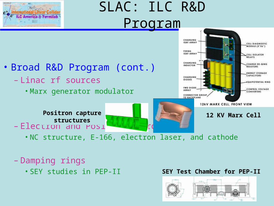
SLAC: ILC R&D Program
• Broad R&D Program (cont.)– Linac rf sources
• Marx generator modulator
– Electron and Positron sources• NC structure, E-166, electron laser, and cathode
– Damping rings • SEY studies in PEP-II
SEY Test Chamber for PEP-II
Positron capturestructures
12 KV Marx Cell
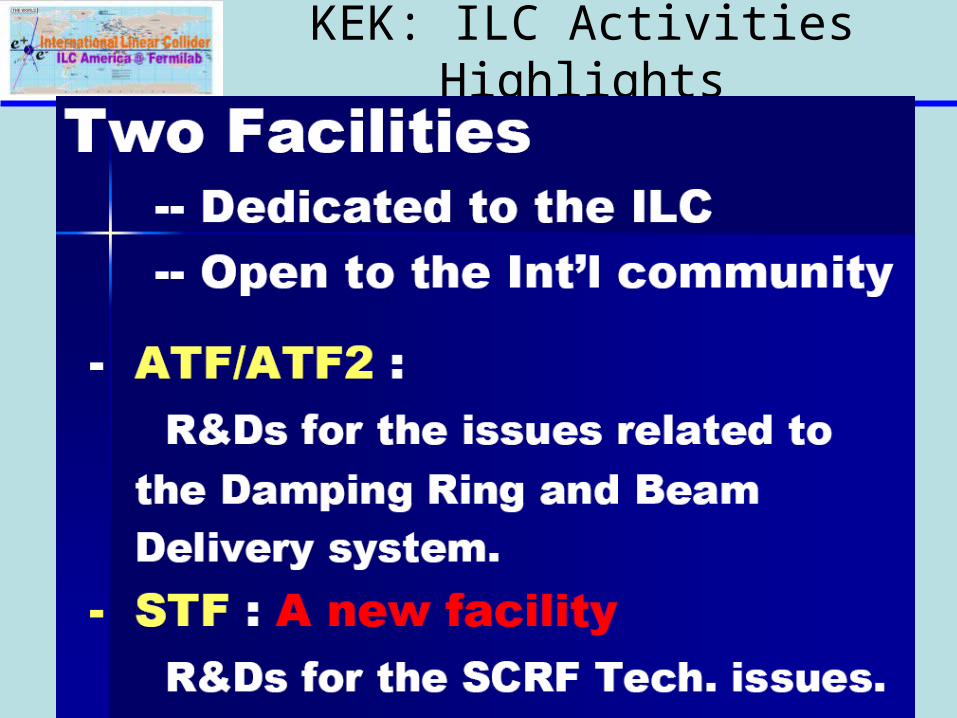
KEK: ILC Activities Highlights
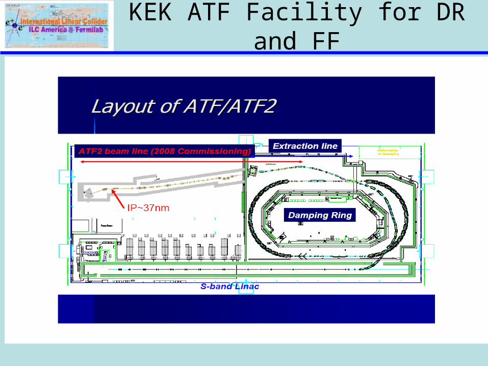
KEK ATF Facility for DR and FF

KEK: Main Linac RF Unit R&D
Goal: Achieve Higher Gradient >40 MV/m in a new Cavity Design

Summary• After the technology selection the ILC Collaboration has made considerable progress towards the design of the ILC.
• The Baseline and Alternate design for each major Accelerator subsystems were defined at Snowmass 2005.
• The ILC-GDE has a approved the Baseline Configuration Document.
• The ILC-GDE is developing the ILC Reference Design Report, with cost estimate. It is expected to be done by the end of CY06
• The ILC R&D around the world is moving fast with focus on key Accelerator Issues.