on multicast capacity and delay in cognitive radio mobile
TRANSCRIPT

1536-1276 (c) 2015 IEEE. Personal use is permitted, but republication/redistribution requires IEEE permission. Seehttp://www.ieee.org/publications_standards/publications/rights/index.html for more information.
This article has been accepted for publication in a future issue of this journal, but has not been fully edited. Content may change prior to final publication. Citation information: DOI10.1109/TWC.2015.2435734, IEEE Transactions on Wireless Communications
1
On Multicast Capacity and Delay in CognitiveRadio Mobile Ad-hoc Networks
Jinbei Zhang†, Yixuan Li†, Zhuotao Liu†, Fan Wu‡, Feng Yang†, Xinbing Wang††Dept. of Electronic Engineering
‡Dept. of Computer Science and EngineeringShanghai Jiao Tong University, China
Email: abelchina,lyx1990116,zhuotaoliu,wu-fan,yangfeng,[email protected]
Abstract—In this paper, we focus on the capacity and delaytradeoff for multicast traffic pattern in Cognitive Radio (CR)Mobile Ad-hoc Networks (MANET). In our system model,the primary network consisting of n primary nodes, overlapswith the secondary network consisting of m secondary nodesin a unit square. Assume that all nodes move according toan i.i.d. mobility model and each primary node serves as asource that multicasts its packets to kp primary destinationnodes whereas each secondary source node multicasts its packetsto ks secondary destination nodes. Under the cell partitionednetwork model, we study the capacity and delay for the primarynetworks under two communication schemes: Non-cooperativeScheme and Cooperative Scheme. The communication patternconsidered for the secondary network is Cooperative Scheme.Given that m = nβ (β > 1), we show that per-node capacityO(1/kp) and O(1/ks) are achievable for the primary networkand the secondary network, with average delay Θ(n log kp)and Θ(m log ks), respectively. Moreover, to reduce the averagedelay in the secondary network, we employ a RedundancyScheme and prove that a per-node capacity O(1/ks
√m log ks)
is achievable with average delay Θ(√m log ks). We find that the
fundamental delay-capacity tradeoff in the secondary network isdelay/capacity ≥ O(mks log ks) under both cooperative schemeand redundancy scheme.
Index Terms—Cognitive Radio, Capacity Scaling, NetworkDelay
I. INTRODUCTION
Since the seminal work by Gupta and Kumar [1], the studyof the capacity of wireless networks has received great atten-tion. It is shown that the per-node capacity is Θ(1/
√n logn)
for unicast traffic pattern, where n is the number of nodesin the network [1]. Compared with the unicast traffic pat-tern where packets are sent from a source node to anotherdestination node, the multicast traffic pattern exhibits thefollowing property: packets from source nodes are delivered tomultiple destination nodes where some links can be shared bydifferent destinations. Therefore, the multicast traffic patternconsumes less spatial and frequency resource required toestablish communication among all the destinations.
Compared to the capacity scaling in static network models,mobility has been leveraged to improve the capacity bounds.In [2], Grossglauser et al. demonstrated that the per-nodecapacity Θ(1) is achievable under independent and identicallydistributed (i.i.d) mobility model. However, one significan-t performance metric in wireless networks, other than thethroughput, is under-studied in [2], e.g., the communication
delay. This motivated later research to explore the relationshipbetween delay and throughput. In [3], Neely et al. studiedthe capacity-delay tradeoff in cell partitioned MANET byintroducing the redundancy scheme which reduced delay bysacrificing capacity. They developed communication schemesto achieve per-node capacity Θ(1), Θ( 1√
n) and Θ( 1
n logn ) withaverage delay Θ(n), Θ(
√n) and Θ(log n), respectively, which
implies that the capacity-delay tradeoff has the characteristicsthat delay
capacity > O(n). Later on, the capacity-delay tradeofffor unicast networks was thoroughly studied using variousmobility models such as the random walk model [4], therandom way point mobility model [5] and the constrainedmobility model [6], [7].
For the multicast traffic pattern, Li et al. [8] studied thecapacity in static networks where each node sends messagesto k − 1 destinations. Based on the interference model, theydemonstrated that the per-node capacity is Θ( 1√
kn logn) if
k = O( nlogn ) whereas the per-node capacity is Θ( n
logn ) whenk = Ω( n
logn ). This result can be seen as a generalization oftwo different traffic patterns: unicast [1] and broadcast [9].Some relevant works can also be found in [10]-[14]. In [15],Wang et al. studied the capacity and delay tradeoff in cellpartitioned MANET under a multicast traffic pattern. Theyproved that the per-node capacity and delay are O(1/k) andΘ(n log k) respectively if no redundant relay nodes are used,and O(1/k
√n log k) and Θ(
√n log k) respectively otherwise.
All the aforementioned results focus only on the throughputscaling and delay analysis for a stand-alone network. Recently,the ever-growing demand for frequency resources has motivat-ed the study of cognitive radio (CR) networks to efficientlyutilize the idle spectrum in the time and space domain. CRnetworks consist of two different networks: primary networkand secondary network. In CR networks, primary users have ahigher priority when accessing the spectrum, while secondaryusers opportunistically access the licensed spectrum withoutdeteriorating the performance of primary users. Specifically,the secondary network can have “vacuum” space to transmitwhen primary users are idle. Also, secondary nodes within theinterference range of any primary nodes that are transmittingor receiving messages cannot have spectrum opportunitiesto transmit. Different from the stand-alone network, the in-teraction between primary and secondary users have to beconsidered when studying the throughput and delay scaling
1536-1276 (c) 2015 IEEE. Personal use is permitted, but republication/redistribution requires IEEE permission. Seehttp://www.ieee.org/publications_standards/publications/rights/index.html for more information.
This article has been accepted for publication in a future issue of this journal, but has not been fully edited. Content may change prior to final publication. Citation information: DOI10.1109/TWC.2015.2435734, IEEE Transactions on Wireless Communications
2
results in CR networks. Previous analysis for stand-alonenetworks is therefore not directly applicable to CR networks.
The study of capacity and delay scaling laws for boththe primary and secondary network is a relatively new andchallenging field. In [16] and [17], the authors investigatedthe capacity scaling of a homogeneous cognitive networksfor unicast traffic by introducing a preservation region aroundprimary receivers. Wang et. al [18] extended the CR networkcapacity scaling analysis to multicast traffic patterns underthe Gaussian channel model. Interestingly, all these worksshowed that both the primary and secondary networks canachieve similar or the same performance bounds as if theycan essentially be regarded stand-alone networks when thesecondary network has a higher density than the primary one.Note that existing works mainly focus on static CR networksand, to the best of our knowledge, the performance of mobileCR networks has not been investigated before.
Motivated by the fact that mobility can dramatically enhancethe throughput in stand-alone networks, we are interested inits impact on CR networks:
• What throughput and delay scaling law can be achievedunder a multicast traffic pattern in Cognitive Radio Mo-bile Ad-hoc Networks (CR MANET)?
• What is the delay and capacity tradeoff characteristic inCR MANET?
In this paper, we first adopt a non-cooperative scheme1
to investigate the achievable per-node capacity and delay forthe primary network, where one source is supposed to sendmessages to kp destinations. We then consider the coop-erative mode to give a unified presentation of the routingscheme. Next, we focus on the capacity and delay analysisfor the secondary network under a cooperative scheme anda redundancy scheme2, respectively. Finally, we introduce adestination oriented redundancy scheme3 to efficiently utilizethe network resources in the secondary network. The majorcontributions of this paper are as follows:
• We investigate the impact of mobility model for both theprimary network and the secondary network. Transmis-sion queues are employed to analyze the capacity anddelay for CR MANET. Our results show that mobilitycan significantly enhance the capacity performance forboth the primary and secondary networks.
• This paper is a nontrivial generalization of previous worksince we directly study the capacity and delay undera multicast traffic pattern. Different with the mobilitymodel studied in [19] and [20], where the primary nodesare static and only the secondary nodes have mobility, ourmodel assumes that both the primary and secondary net-works can have mobility. Our results can be specializedto the unicast and broadcast traffic by setting the numberof destinations to be 1 and n−1 for the primary network(1 and m− 1 for the secondary network), respectively.
1A non-cooperative scheme means that destinations cannot act as relayswithin the same multicast group. Otherwise, it is called a cooperative scheme.
2Redundancy scheme means that there can be multiple nodes acting asrelays for a packet.
3Destination oriented redundancy scheme means that every destination thathas received a packet can act as a relay for the packet.
• We show that both the primary network and the secondarynetwork can achieve the same throughput as the optimalone established for a stand-alone MANET in [15], ifthe number of secondary users m is larger than that ofprimary users n scaled by m = nβ (β > 1). Specifically,under the cooperative scheme, the per-node capacityO(1/kp) and O(1/ks) are achievable for the primarynetwork and the secondary network, with average delayΘ(n log kp) and Θ(m log ks), respectively.
• We introduce redundancy into the secondary network andprove that the tight bound of transmission delay can bereduced to Θ(
√m log ks) with an achievable per-node
capacity O(1/ks√m log ks) if there are redundant relay
nodes. Moreover, we also proposed destination orientedredundancy scheme to utilize wireless resources efficient-ly in practical operation. We find that the fundamentalcapacity-delay tradeoff in the secondary network is char-acterized by delay/capacity ≥ O(mks log ks) under boththe cooperative scheme and the redundancy scheme.
The rest of the paper is organized as follows. In sectionII, we introduce our network model and the main definitions.In section III, we present the communication schedules forboth the primary and the secondary network. In sections IVand V, we give our main results of capacity and delay in theprimary network and secondary network, respectively. Finally,we conclude this paper in section VI.
II. NETWORK MODEL
Cell Partitioned Network Model: Our network model isbased on the model used in [3]. Consider a unit square witha co-existing primary network and secondary network, wherethe two networks share the same space, time and frequencydomain but with different priorities in accessing the spectrum.The primary nodes and secondary nodes are distributed ac-cording to a Homogeneous Poisson Process (HPP) of densityn and m, respectively. We assume that n and m satisfym = nβ (β > 1), which indicates that the secondary networkhas a higher density than the primary network. It can beproved [21] that the total numbers of primary nodes andsecondary nodes within the unit area are of order Θ(n) andΘ(m), respectively. For simplicity, we will assume that thereare n mobile primary nodes and m mobile secondary nodesdistributed over the square throughout the paper. We furtherdivide the primary network into w = Θ(n) non-overlappingcells with equal area Θ( 1n ) and divide the secondary networkinto c = Θ(m) non-overlapping cells with equal area Θ( 1
m )as illustrated in Figure 1. The node density τp is n
w for theprimary network and τs is m
c for the secondary network.Therefore, both τp and τs are of constant order Θ(1).
Traffic Pattern: In a multicast traffic pattern, we assumethat there are a set Vp = v1p, v2p, . . . , vnp of mobile primarynodes and another set Vs = v1s , v2s , . . . , vms of mobilesecondary nodes in the unit square. For each multicast groupin the primary network, there is a source node vi ∈ Vp andkp destinations that are randomly and independently chosen.Multicast groups in the secondary network can be similarlydefined.
1536-1276 (c) 2015 IEEE. Personal use is permitted, but republication/redistribution requires IEEE permission. Seehttp://www.ieee.org/publications_standards/publications/rights/index.html for more information.
This article has been accepted for publication in a future issue of this journal, but has not been fully edited. Content may change prior to final publication. Citation information: DOI10.1109/TWC.2015.2435734, IEEE Transactions on Wireless Communications
3
1( )m
Θ
1( )n
Θ
Inactive secondary cells
Active secondary cells
Primary cells
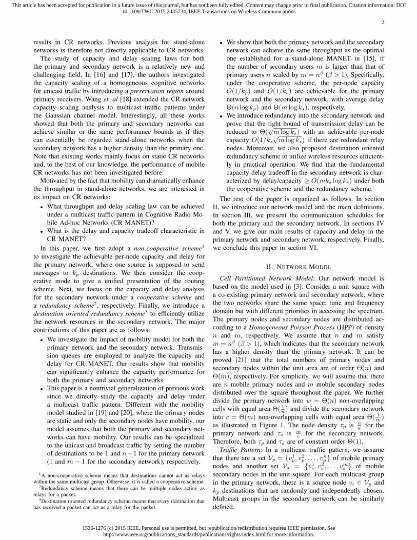
Fig. 1. Illustration of cell partitioned network model: the blue primary cellsrepresent the active cells where a pair of primary nodes in a cell (denoted bygreen spots) are transmitting. No spectrum opportunities will be available forsecondary nodes located in the region of active primary cells. Thus we colorthe secondary cells blue to indicate that they are inactive due to the presenceof active primary cells. All the secondary nodes in the inactive secondarycells will buffer their packets without transmitting.
Mobility Model: Assuming that time is slotted, we adopt theideal i.i.d. fast mobility model. The initial position of eachnode (primary or secondary) is equally likely to be in anyof the (primary or secondary) cells independent of the othernodes’ positions. At the beginning of the next time slot, nodescan roam to a new cell randomly in the network. Since weadopt the fast mobility model, the time it takes for a nodeto move from one cell to another has negligible delay. Underthe mobility model, packets are carried by the nodes (eitherthe source or relay nodes) until they reach their correspondingdestination nodes.
Interference: In CR MANET, there are three kinds ofinterference: inter-cell interference, intra-cell interference andinter-network interference. To avoid intra-cell interference, weassume that each cell (primary or secondary) allows at mostone transmission during a time slot. In order to mitigateinter-primary-cell interference, neighboring primary cells haveto transmit over orthogonal frequency bands and four bandsare enough for the whole primary network to ensure thiscondition [3]. The inter-secondary-cell interference can beavoided by adopting a 25-TDMA4 schedule for the secondarynetwork. Since the primary nodes have higher priority in usingthe spectrum, the secondary network has to operate withoutcausing severe interference to the primary network. To limitthe inter-network interference, no spectrum opportunities willbe available for a secondary node if it resides in the regionof an active primary cell. If a secondary node roams to aninactive secondary cell at a time slot, it will buffer its packetswithout transmitting.
Capacity: We assume that the exogenous rate of packets toeach primary and secondary source node are both a Bernoulliprocess with rate λp and λs packets per slot, respectively. Thenetwork is stable when there exists a scheduling policy toensure that the packet queue for each node will not approach
4The TDMA scheme can also be 9-TDMA or 16-TDMA schemes, whichis used for concurrently transmissions and since we focus on scaling perfor-mance, the constant will not affect our results.
infinity as time approaches infinity and each packet can bedelivered to its k (k = kp for the primary network andk = ks for the secondary network) distinct destinations. Wedefine λp and λs as the achievable per-node capacity for theprimary network and the secondary network, respectively. Forother stochastic arrival process with the same average rate, theanalysis can be treated similarly and the throughput will notchange [3].
Delay: In the multicast communication pattern, the delayin the primary (secondary) network Dp (Ds) is defined as thetime interval between the time that the packet departs from theprimary (secondary) source node, and the time that it arrivesat all the kp (ks) destination nodes.
Transmission Queues: We analyze the communication delayusing queueing theory. For both the primary network and thesecondary network, packets are transmitted through source-to-destination queues, source-to-relay queues and relay-to-destination queues according to their specific communicationschemes.
Knuth Notation: Given two functions f(n) > 0, g(n) > 0:f(n) = o(g(n)) means limn→∞ f(n)/g(n) = 0; f(n) =O(g(n)) means limn→∞ sup f(n)/g(n) < ∞; f(n) =ω(g(n)) is equivalent to g(n) = o(f(n)); f(n) = Ω(g(n))is equivalent to g(n) = O(f(n)); f(n) = Θ(g(n)) meansf(n) = O(g(n)) and g(n) = O(f(n)).
The key notations used in this paper are listed in thefollowing table.
TABLE INOTATIONS
Notation Definitionn (m) The number of primary (secondary) nodes.w (c) The number of primary (secondary) cells.τp (τs) The node density of each primary (secondary) cell.kp (ks) The number of primary (secondary) destinations.λp (λs) The throughput of primary (secondary) nodes.Dp (Ds) The delay of primary (secondary) packets.
III. COMMUNICATION SCHEME
In this section, we will introduce the communicationschemes for both the primary network and the secondarynetwork. Since the primary network has a higher priority, itis oblivious to the existence of the secondary network. Thesecondary network adaptively chooses to transmit based onthe given primary transmission scheme.
A. Communication Scheme for the Primary Network
In the primary network, we assume that the packets aredelivered using at most two hops. The source node eithersends packets directly to all the destinations or to one ofthe relays. Then the relay will forward the packet to all thecorresponding destinations. Each cell becomes active when atleast one successful transmission can happen. In the follow-ing, we consider two schemes: non-cooperative scheme andcooperative scheme.
Non-cooperative Scheme:
1536-1276 (c) 2015 IEEE. Personal use is permitted, but republication/redistribution requires IEEE permission. Seehttp://www.ieee.org/publications_standards/publications/rights/index.html for more information.
This article has been accepted for publication in a future issue of this journal, but has not been fully edited. Content may change prior to final publication. Citation information: DOI10.1109/TWC.2015.2435734, IEEE Transactions on Wireless Communications
4
For an active cell containing at least two primary nodes, thetransmissions are conducted in the following way.
1) If at least one primary source-destination pair can befound in the cell, then randomly pick one pair to finishthe communication.
2) If no source-destination pair can be found in the cell,perform the following two schedules with equal proba-bility:
• Source-to-Relay Transmission: Randomly pick onesource node as the sender. If at least one normalrelay node5 is available for the source node in thesame cell, pick the relay node as the receiver tofinish the transmission.
• Relay-to-Destination Transmission: If one relay n-ode, carrying a packet destined for a primary desti-nation node, can be found in one cell and at least onecorresponding “pristine” primary destination node 6
stays within the same cell, pick the relay node asthe sender and one of these “pristine” destinationnodes as the receiver to finish the transmission.
3) If neither of the above two items can be satisfied, notransmission will take place in this cell. A packet willbe discarded whenever all its kp primary destinationshave received it7.
Cooperative Scheme:According to the previous scheme, one primary destination
node cannot serve as a relay for other destinations within thesame multicast group. That is to say, a certain destination nodeeither receives packets from corresponding source node oracts as a relay for other multicast groups. However, under thecooperative scheme, we will no longer discriminate betweenthe destination nodes and normal relay nodes. The first nodethat the source delivers its packet to will be treated as a relaynode irrespective of whether it is a destination node or not.Once a destination node is chosen as a relay node, it can sendpackets to other destination nodes (possibly within the samemulticast group or not). Under the cooperative scheme forthe primary network, the following two transmission patternshappen with equal probability:
1) Source-to-Relay Transmission: If one primary sourcenode can be found in the cell and one relay node isavailable in the same cell, pick the source node as thesender and one relay node as the receiver to finish thetransmission.
2) Relay-to-Destination Transmission: If one relay node,carrying a packet destined for primary destination n-odes, can be found in this cell and meanwhile at leastone corresponding “pristine” primary destination noderesides within the same cell, pick the relay node as the
5For a certain multicast group, all nodes in the area except for thosedestination nodes within this multicast group can be treated as normal relaynodes for this multicast group.
6A “pristine” primary destination node represents a destination node whichhas not received the desired packet, that the relay node is carrying. This isthe same when we call a node as a “pristine” secondary destination node.
7The acknowledge information can be delivered when the source anddestinations have transmission opportunities. Since this information size isvery small compared to the packet size, its cost can be neglected.
sender and one destination node as the receiver to finishthe transmission.
If neither of the above two items mentioned can be satisfied,no transmission will take place in this cell.
B. Communication Scheme for the Secondary Network
Primary nodes have priority to access the channel. Sec-ondary nodes should choose their action based on the activityof primary nodes. When primary nodes is transmitting in someprimary cells, secondary nodes inside would keep silent. Whenprimary nodes is silent, secondary nodes may transmit, whenit will not cause severer interference to primary nodes. Sincethe density of secondary nodes is larger than that of primarynodes in order sense, the communication range employedby the secondary nodes can be much smaller than that ofprimary nodes. Therefore, the interference that secondarynodes cause can be tolerable for primary nodes if we scheduleappropriately. And the schemes analyzed in Section V are allbased on this main intuition.
From the capacity analysis for the primary network in sec-tion IV, we find that the cooperative scheme can achieve betterperformance than the non-cooperative scheme. Therefore, weonly consider the cooperative scheme for the secondary net-work without considering the non-cooperative scheme further.The cooperative scheme in the secondary network is similarto that in the primary network.
Note that in the cooperative scheme, only one relay node isused for sending a single packet. For the secondary network,we further propose a redundancy scheme in order to reducethe delay, which allows more than one relay to be used fordelivering a single packet. Then, we improve the redundancyscheme by avoiding the use of additional nodes other thanthe destination nodes which have received packets to serve asrelays. This is referred to as destination oriented redundancyscheme. In this way, we are able to better utilize networkresources under this scheme. This communication schedulewill be discussed in more details later on in section V.
IV. CAPACITY AND DELAY ANALYSIS FOR THEPRIMARY NETWORK
In this section, we will study the capacity and delay tradeoffin the primary network. Denote the probability that there areat least two primary nodes in one cell by p1, which is givenby
p1 = 1− (1− 1
w)n −
(n
1
)1
w(1− 1
w)n−1
= 1− (1− 1
w)n − n
w(1− 1
w)n−1
∼ 1− (1 + τp)e−τp .
Denote the probability of finding a source-destination pairin the primary network by p2. To get p2, we need to modelthe primary nodes as mutually exclusive groups according tothe following definition.
Definition 1: kp + 1-grouped Primary Network: Foreach source node vip ∈ Vp in the primary network, we putit and its kp destination nodes into a group, denoted by Gip.
1536-1276 (c) 2015 IEEE. Personal use is permitted, but republication/redistribution requires IEEE permission. Seehttp://www.ieee.org/publications_standards/publications/rights/index.html for more information.
This article has been accepted for publication in a future issue of this journal, but has not been fully edited. Content may change prior to final publication. Citation information: DOI10.1109/TWC.2015.2435734, IEEE Transactions on Wireless Communications
5
Then we will have nkp+1
8 groups over the whole primarynetwork. We also assume that Gip
∩Gjp = ∅, for i = j, and
i, j ∈ [1, nkp+1 ].
Note that in the kp + 1-grouped primary network, eachnode within Gip can be a source node or destination node.Thus, any two nodes from the same group are a source-destination pair. However, for any randomly chosen two nodesfrom different groups, they cannot be viewed as a source-destination pair. Then, we get
p2 = 1− [(1− 1
w)kp+1 +
(kp + 1
1
)1
w(1− 1
w)kp ]
nkp+1
= 1− (1− 1
w)
nkpkp+1 (1 +
kpn)
nkp+1
∼
1− e−τpeτ = 0, if kp = o(n);
1− (1 + τp)e−τp , if kp = Θ(n).
A. Capacity and Delay Analysis of the Non-cooperativeScheme
In this subsection, we will study the achievable capacity andcommunication delay in the primary network when destinationnodes cannot relay packets to other destination nodes withinthe same multicast group. Our main results are presented inthe following.
Theorem 1: In a cell-partitioned network with overlappingn primary nodes and m secondary nodes, the achievableper-node capacity for the primary network under the non-cooperative scheme is λp = O(1/kp) with an average delayE[Dp] = Θ(n log kp).
Proof: In each time slot, a new packet arrives at a primarysource node vip in the group Gip with rate λp. Denote the ratethat the packet is transmitted to a primary destination node orhanded over to a relay node by R1 and R2, respectively. Thenwe have
λop = R1 +R2.
Since the transmission of the source-to-relay and the relay-to-destination have equal probability, R2 is also equal tothe rate at which the relay nodes are sending packets tothe primary destinations. Thus, in every time slot, the totalrate of transmission opportunities over the primary network isn(R1+2R2). Meanwhile, a transmission occurs in any givencell with probability p1. Hence we obtain
wp1 = n(R1 + 2R2). (1)
Similarly, since p2 is the probability that a primary source-destination pair can communicate with each other in one cell,we have
wp2 = nR1. (2)
Combining Equations (1) and (2), we have
R1 =p2τp
; R2 =(p1 − p2)
2τp.
Then we obtain that the total service rate for one primarysource queue is λop =
(p1+p2)2τp
.
8Here we assume that n is divisible by kp + 1.
Now, we will deal with the traffic delay for the primarynetwork using queueing theory techniques similar to [3][15].There are two possible routing strategies for a primary packetto reach its destination: the 1-hop source-to-destination pathand the 2-hop source-relay-destination path. For the first strate-gy, the source will transmit the packet to all the kp destinationsdirectly and the delay consists of only the queueing delay atthe source. For the second strategy, the packet will first sentto a relay and the relay will transmit the packet to all the kpdestinations. Hence, delay is composed of the queueing delaysat both the source and the relay nodes.
If one packet is directly sent from the source node todestination nodes, it will wait at the source for a time periodDps→d before the source can find its corresponding destinations
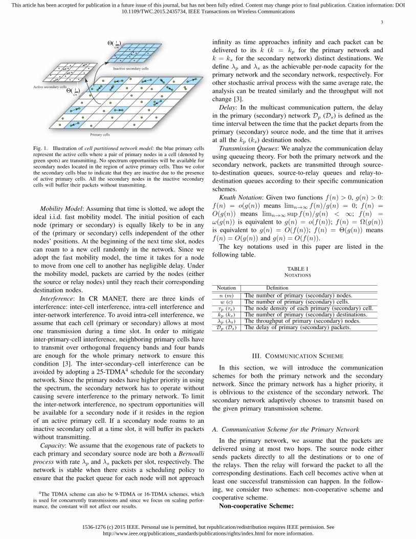
to forward this packet. Since a source node transmits packetsto kp destinations for multicast traffic, we assume that thereare kp identical copies of the packet in the buffer of thesource node. Thus, we can model a source queue as a setof kp sub-queues, in which each sub-queue is intended forone destination. Since the rate of each sub-queue is assumedto be the same, and the transmission scheme is randomlyoperated for every sub-queue, the kp sub-queues can be seenas independent source-destination routings, as illustrated inFigure 2.
Source Packet
Destination 1
Destination 2
Destination 3
Destination
Destination
1kp−
kp
jP
2
jP
3
jP
1pk
jP−
pk
jP
pλ p pk λO
subλ
1
jP1
jP
2
jP
3
jP
1pk
jP−
pk
jP
Fig. 2. Illustration of the source-to-destination transmission process in theprimary network under the non-cooperative scheme.
Denote the delay in each routing by Djs→d. Then we have
Dps→d = max
1≤j≤kpDj
s→d.
To calculate the delay in this scenario, we first obtain theinput and output rate for each source-to-destination sub-queuein the following lemma.
Lemma 1: Each source-to-destination sub-queue is aM/M/1 queue corresponding to one destination node withinput rate λisub =
λpR1
λop
and service rate λosub =R1
kp.
Proof: It is clear that the probability that the packet willbe sent directly from the source to the destination is R1
λop
.Hence, the input rate of each sub-queue is
λisub = λpps→d =λpR1
λop.
The output rate of each sub-queue is equal to the communi-cation rate of a source-to-destination pair λosub =
R1
kpbecause
1536-1276 (c) 2015 IEEE. Personal use is permitted, but republication/redistribution requires IEEE permission. Seehttp://www.ieee.org/publications_standards/publications/rights/index.html for more information.
This article has been accepted for publication in a future issue of this journal, but has not been fully edited. Content may change prior to final publication. Citation information: DOI10.1109/TWC.2015.2435734, IEEE Transactions on Wireless Communications
6
the kp destinations are equally likely to get the packet directlyfrom the source.
Thus, the expected queueing time for each sub-queue is1
λosub−λ
isub
. To obtain the maximum expected queueing timefor all the sub-queues, we first introduce the following lemma[15].
Lemma 2: Suppose X1, X2, . . . , Xk are continuous i.i.dexponential random variables with expectation of 1/a. DenoteXmax = maxX1, X2, . . . , Xk, then
EXmax =
Θ(1/a), k = 1Θ(log k/a), k > 1
.
Therefore, we can conclude that
Dps→d =
Θ
(1
R1kp
−λpR1λop
), kp = 1
Θ
(log kp
R1kp
−λpR1λop
), kp > 1
. (3)
On the other hand, if the packet is transmitted through arelay node, the relay node will hold the packet and transmitthe packet to all destinations. We denote the delay from sourceto relay by Dp
s→r and the delay from relay to destination byDpr→d. Then we have the following lemma.Lemma 3: In the first phase of the 2-hop routing strategy
under the non-cooperative scheme, the expected delay beforea primary source node can find a normal relay node to send apacket is equal to 1/(R2 − λp
R2
λop).
Proof: The probability that a packet is handed over by arelay in the primary network is R2
λop
. Thus, for a source nodewith input rate λp, the rate that the packets will be deliveredto a relay is λpR2
λop
. Also note that the available service rate fora source to a relay is R2. Therefore we conclude this lemma.
Next, we will calculate the delay in the second phase Dpr→d.
Note that the probability that the packet is sent to a relay nodeis pis→r =
R2
λop(n−kp−1) , because all these n− kp − 1 primary
nodes outside the group Gip are equally likely to be chosen asa relay under the non-cooperative scheme. Then the input ratefor a relay-to-destination queue in the primary network λir is
λir = λppis→r =
λpR2
λop(n− kp − 1).
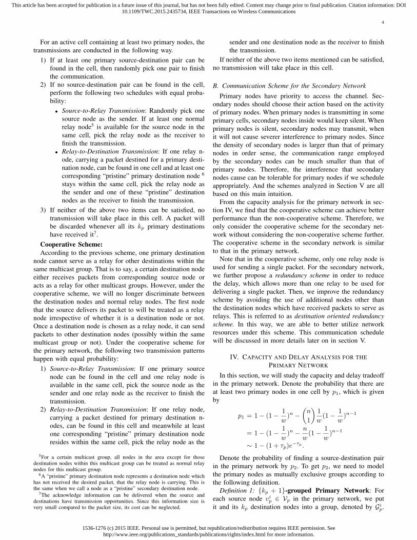
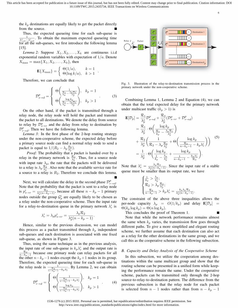
Hence, similar to the previous discussion, we can modelthis process as a packet transmitted through kp independentsub-queues and each destination is associated with one fixedsub-queue, as shown in Figure 3.
Thus, using the same technique as in the previous analysis,the input rate of one sub-queue is kpλir and the output rate is
R2
n−kp−1 because one primary node can relay packets for allthe other n−kp−1 nodes except the kp+1 nodes in its group.Therefore, the expected queueing time for each sub-queue inthe relay node is 1
R2n−kp−1−kpλi
r
. By Lemma 2, we can obtain
Dpr→d =
Θ
(1
R2n−kp−1−kpλi
r
), kp = 1
Θ
(log kp
R2n−kp−1−kpλi
r
), kp > 1
. (4)
Relay Packet
Destination 1
Destination 2
Destination kp
ii
ii
rλi
p rk λ
jP
1
jP1
jP1
1pn k− −
2
3
2pn k− −
2
jP
3
jP
1pk
jP−
pk
jP
2
jP
pk
jP
Fig. 3. Illustration of the relay-to-destination transmission process in theprimary network under the non-cooperative scheme.
Combining Lemma 1, Lemma 2 and Equation (4), we canobtain that the total expected delay for the primary networkunder multicast traffic (kp > 1) is
E[Dp] =R1
λopDps→d +
R2
λop(Dp
s→r +Dpr→d)
=R1
λop·Θ
(log kp
R1
kp− λpR1
λop
)
+R2
λop
(1
R2 − λpR2
λop
+Θ
(log kp
R2
n−kp−1 − kpλir
))=
1
λop·Θ
(log kp1kp
− λp
λop
+log kp
1n−kp−1 − kpλi
r
R2
).
(5)
Note that λir =λpR2
λop(n−kp−1) . Since the input rate of a stable
queue must be smaller than its output rate, we have1kp>
λp
λop;
R2 > λpR2
λop;
R2
n−kp−1 > kpλir =
kpλpR2
λop(n−kp−1) .
The constraint of the above three inequalities allows theper-node capacity λp = O(1/kp) and delay E[Dp] =Θ(kp log kp) = Θ(n log kp).
This concludes the proof of Theorem 1.Note that while the network performance remains almost
the same when kp varies, the transmission flow goes throughdifferent paths. To give a more simplified and elegant routingscheme, we further assume that each destination can also actas a relay for the other destinations in the same group, and wecall this as the cooperative scheme in the following subsection.
B. Capacity and Delay Analysis of the Cooperative Scheme
In this subsection, we utilize the cooperation among des-tinations within the same multicast group and show that therouting scheme can be presented in a unified form while keep-ing the performance remain the same. Under the cooperativescheme, packets can be transmitted only through the 2-hopsource-to-relay-to-destination pattern. The difference from theprevious subsection is that the relay node for each packetis selected from n − 1 nodes rather than from n − kp − 1

1536-1276 (c) 2015 IEEE. Personal use is permitted, but republication/redistribution requires IEEE permission. Seehttp://www.ieee.org/publications_standards/publications/rights/index.html for more information.
This article has been accepted for publication in a future issue of this journal, but has not been fully edited. Content may change prior to final publication. Citation information: DOI10.1109/TWC.2015.2435734, IEEE Transactions on Wireless Communications
7
nodes. Our main results under this scenario are presented inthe following theorem.
Theorem 2: In a cell-partitioned network with overlappingn primary nodes and m secondary nodes, the achievable per-node capacity for the primary network is λp = O(1/kp) withaverage delay E[Dp] = Θ(n log kp) under the cooperativescheme.
Proof: The proof is similar as that of Theorem 1. Toavoid confusion, we will adopt the same mathematical symbolsas the previous subsection. Since only the 2-hop source-to-relay-to-destination pattern is available under the cooperativescheme, we have R2 = λop = p1
2τp. For the source-to-relay
delay Dps→r, we have the following lemma.
Lemma 4: In the first phase of 2-hop routing strategy underthe cooperative scheme, the expected delay before a primarysource node can find a relay node to send a packet is
Dps→r =
1
R2 − λpR2
λop
. (6)
Proof: The proof is quite similar to that of Lemma 3 andwe omit it here.
Now we will discuss the delay in the second phase Dpr→d.
Under the cooperative scheme, when destination nodes canserve as relay nodes for any multicast group, the input ratefor a relay-to-destination queue λir is
λir =λpn− 1
.
If a destination node is chosen as a relay node, then it onlyneeds to transmit packets to the remaining kp − 1 destinationnodes. Otherwise, a normal relay node must send packets toall the kp destination nodes. It is clear that whether kp− 1 orkp destination nodes that are supposed to receive the packetmakes no difference to the delay in an order sense. Therefore,we assume that a relay node has to relay packets for kpdestination nodes regardless of whether it is a destinationnode or not. Hence, using the same technique as the previoussubsection, we have that the input rate for a sub-queue is kpλirand the output rate is R2
n−1 . Therefore, the expected queueingtime for each sub-queue in the relay node is 1
R2n−1−kpλi
r
.
According to Lemma 2, we can obtain
Dpr→d =
Θ
(1
R2n−1−kpλi
r
), kp = 1
Θ
(log kp
R2n−1−kpλi
r
), kp > 1
. (7)
Combining Equations (6) and (7), we have that the totalexpected delay under multicast traffic (kp > 1) is
E[Dp] = Dps→r +Dp
r→d
=1
R2 − λpR2
λop
+Θ
(log kp
R2
n−1 − kpλir
).
(8)
From Equation (8), it is clear that the following twoinequalities should hold:
λp < λop;
kpλir ∼
λpkpn−1 < R2
n−1 .
From the above two inequalities, it is easy to see that theper-node capacity O(1/kp) is achievable under the cooperativescheme regardless of the order of kp. Note that the expecteddelay E[Dp] is still in the order of Θ(n log kp), which impliesthat cooperative schemes use a simplified algorithm whilekeeping a same performance as non-cooperative schemes.
V. CAPACITY AND DELAY ANALYSIS FOR THESECONDARY NETWORK
In this section, we will discuss the capacity and delaytradeoff in the secondary network. Unlike the scheme in theprimary network, a node in the secondary network can onlyopportunistically transmit whenever it is outside the region ofactive primary cells. For these active secondary cells, we adopta 25-TDMA scheme to avoid interference. In the following,we first analyze the expected capacity and delay under thecooperative scheme. We then introduce the redundancy schemeand destination oriented redundancy scheme to help reducethe delay and efficiently utilize the network resources for thesecondary network.
A. Capacity and Delay Analysis of the Cooperative Scheme
The following lemma indicates that, with the communica-tion schemes defined previously, the secondary nodes (whethersource nodes or relay nodes) have opportunities to deliver theirpackets. Later we prove that the whole secondary networkappears to have the same capacity and delay performance asa stand-alone MANET in the order sense.
Lemma 5: With the proposed communication scheme, thefollowing two results hold:
1) In each time slot, a constant fraction of the secondarycells is outside the region of active primary cells, whichcan be scheduled successfully for transmission.
2) Each individual secondary cell has a constant probabilityfor spectrum access to transmit.
Proof: Let cq(n) be the fraction of primary cells with qnodes ( q ≥ 0 ). According to Lemma 1 in [22], cq(n) =e−1/q! w.h.p.. Then 1− 2e−1 ≈ 0.26 fraction of the primarycells contains at least two primary nodes w.h.p.. This impliesthat the remaining fraction of primary cells may not be activeand this allows the secondary nodes access to the spectrum fortransmitting. Thus, we conclude the first part of the lemma.
The above part implies a constant transmission opportunityfor the overall secondary cells. We have to further considerthe transmission opportunity of each individual secondary cell.Recall that the secondary network adopts a 25-TDMA schemewith adjacent-neighbor communication. In each primary timeslot, we have a complete secondary TDMA frame in ourcommunication scheme. Each active secondary cell will beassigned with at least one active secondary TDMA slot withineach secondary frame. This completes the proof.
Lemma 6: The total service rate for a secondary sourcequeue is λos =
p32τs
, where p3 ∼ 1− (1 + τs)e−τs .
Proof: Denote the probability that there are at least twosecondary nodes in one cell by p3. Then we have p3 = 1 −(1− 1
c )m −
(m1
)1c (1−
1c )m−1 ∼ 1− (1 + τs)e
−τs .

1536-1276 (c) 2015 IEEE. Personal use is permitted, but republication/redistribution requires IEEE permission. Seehttp://www.ieee.org/publications_standards/publications/rights/index.html for more information.
This article has been accepted for publication in a future issue of this journal, but has not been fully edited. Content may change prior to final publication. Citation information: DOI10.1109/TWC.2015.2435734, IEEE Transactions on Wireless Communications
8
Similar to the cooperative scheme in the primary network,packets are transmitted only through the 2-hop source-relay-destination paths under the cooperative scheme in the sec-ondary network. Since the transmission for source-to-relay andrelay-to-destination have equal probability, λos is also equal tothe rate at which the relay nodes are sending packets to thesecondary destinations. Thus, in every time slot, the total rateof transmission opportunities over the secondary network is2mλos. Meanwhile, a transmission occurs in any given cellwith probability p3. Hence, we obtain
cp3 = 2mλos. (9)
Therefore, the total service rate for a secondary source queueis λos =
p32τs
.Our results on achievable per-node capacity and transmis-
sion delay are given in the following.Theorem 3: In a cell-partitioned network with overlapping
n primary nodes and m secondary nodes, the achievable per-node capacity for the secondary network under the cooperativescheme is λs = O(1/ks) with average delay E[Ds] =Θ(m log ks).
Proof: For the 2-hop source-relay-destination communi-cation strategy, both the queueing time at the secondary sourcenode and relay node are accounted for in the delay. We denotethe delay in first phase (from a secondary source node to arelay node) by Ds
s→r and delay in second phase (from a relaynode to all the ks secondary destination nodes) by Ds
r→d.Then, similar to Lemma 3 in previous section, we have thefollowing lemma.
Lemma 7: In the first phase of the cooperative scheme inthe secondary network, the expected delay for a secondarysource to send one packet to a relay node equals 1
c125 p3−λs
,where c1(0 < c1 < 1) is a constant.
Proof of Lemma 7: Since a secondary frame is dividedinto 25 sub-frames, the transmission rate for a secondary celldecreases by a factor of 25. Moreover, according to Lemma5, there is a constant fraction of secondary cells in the unitarea that can access the spectrum. Here we use the constantc1 to represent the overall likelihood that the secondary cellswill be successfully scheduled during one second. Therefore,the input rate and output rate for a secondary source-to-relayqueue are λs and c1
25λ0s, with average delay 1
c125λ
0s−λs
.Now, we need to get the delay in the second phase Ds
r→d.Note that a secondary node relays a packet from a secondarysource node with rate λis = λs
m−1 because all the secondarynodes are equally likely to be chosen as a relay. For a relay-to-destination sub-queue, there will be ks or ks − 1 sources,depending on whether the relay is also a destination for thepacket. Let us regard the input rate for a relay-to-destinationsub-queue to be ksλis.
The output rate of one sub-queue is c1λos
25(m−1) becauseone secondary node can relay packets destined for all theother m − 1 nodes with equal probability. Therefore, theexpected queueing time for each sub-queue in the relay nodeis 1
c1λos
25(m−1)−ksλi
s
. By Lemma 2, we can obtain
Dsr→d =
Θ
(1
c1λos
25(m−1)−ksλi
s
), ks = 1
Θ
(log ks
c1λos
25(m−1)−ksλi
s
), ks > 1
. (10)
Combining Lemma 6 and Equation (10), we have the totalexpected delay for the secondary network under multicasttraffic (ks > 1) as
E[Ds] = Dss→r +Ds
r→d
=1
c125λ
0s − λs
+Θ
(log ks
c1λos
25(m−1) − ksλis
).
(11)
To make sure that the number of packets waiting to betransmitted in each queue does not increase to infinity withtime, the following two constraints must be satisfied.
λs <c125λ
0s;
c1λos
25(m−1) > ksλis.
From the above two inequalities, we obtain λs <c1λ
os
25ks.
Thus, the per-node capacity λs = O(1/ks) and averagedelay E[Ds] = Θ(m log ks) are achievable for the secondarynetwork.
Note that in our system model and communication scheme,the primary network and secondary network achieve per-nodecapacity O(1/kp) and O(1/ks), respectively. Therefore, theco-existence and mutual interference do not affect throughputscaling for cognitive networks.
B. Capacity and Delay Analysis of the Redundancy Scheme
In this part, we will discuss the capacity and delay tradeoffwhen more than one secondary node can serve as a relay, i.e.,the redundancy scheme, for the secondary network.
Intuitively, the time needed for a packet to reach its desti-nations can be reduced by repeatedly sending this packet tomany other secondary nodes, i.e., using more than one nodeas a relay. In this way, the chances that some node carrying anoriginal or duplicate version of the packet finds a destinationwill increase. Thus, it is supposed that adopting the redundan-cy scheme can reduce communication delay although this maynot help to improve the network throughput. Previous works[3] and [15] have also introduced the redundancy scheme fora stand-alone ad hoc network in which the source node sendspackets to more than one relay node. In CR networks, theredundancy scheme is also applicable for both the primarynetwork and the secondary network. However, considering thatsecondary nodes suffer from a larger average-delay than theprimary nodes, we shall introduce this redundancy scheme tothe secondary network to help effectively reduce its end-to-enddelay.
Here, we first show the lower bound of the average delay,which is given in the following.
Theorem 4: In a cell-partitioned network with overlappingn primary nodes and m secondary nodes, no communicationscheme with redundancy can achieve an average delay lowerthan O(
√m log ks) for the secondary network.
1536-1276 (c) 2015 IEEE. Personal use is permitted, but republication/redistribution requires IEEE permission. Seehttp://www.ieee.org/publications_standards/publications/rights/index.html for more information.
This article has been accepted for publication in a future issue of this journal, but has not been fully edited. Content may change prior to final publication. Citation information: DOI10.1109/TWC.2015.2435734, IEEE Transactions on Wireless Communications
9
Proof: We prove this result by considering an ideal situa-tion where the secondary network has only a single secondarysource node that sends a packet to ks destinations. The optimalscheme for the source is to send duplicate versions of thepacket whenever it meets any node that has never received thepacket before. These nodes then act as relays to transmit thepacket to the destinations once they enter the same cell as thedestinations’.
During the time slots 1, 2, . . . , i, let ϑj be the totalnumber of intermediate relay nodes at the beginning of timeslot j (1 ≤ j ≤ i). Clearly, ϑ1 ≤ ϑ2 ≤ · · · ≤ ϑi since thenumber of relays is non-decreasing over time. Note that a relaycan only be generated by the secondary source node, hence atmost one node can be a new relay in every time slot. Thus,ϑi ≤ i for all i ≥ 1. Furthermore, denote the probability that adestination node can meet at least one relay node during timeslots 1, 2, . . . , i by p(i), we have
p(i) = 1−i∏
j=1
(1− 1
c)ϑj
≤ 1− (1− 1
c)i
2
.
However, a destination node that encounters a relay does notnecessarily ensure the transmission can be scheduled sincethe secondary cell in which they meet may not be activeduring that slot. Similar to previous discussion in Lemma 7,a constant c1
25 should be factored in. Hence, the probabilitythat a destination node can successfully receive a packet froma relay during time slots 1, 2, . . . , i is c1p(i)/25. Then, wehave
Pr(Ds ≥ i) ≥ 1− (c125p(i))ks
≥ 1− (c125
)ks(1− (1− 1
c)i
2
)ks
∼ 1− (c125
)ks(1− e−τsi2
m )ks .
(12)
Let i =√
m log ksτs
and ks → ∞, we obtain that
Pr(Ds ≥ i) ≥ 1− (c125
)ks(1− e− log ks)ks
= 1− (c125
)ks(1− 1
ks)ks ≥ 1− c1
25e−1.
Therefore, the average delay in the secondary network withredundancy satisfies
E[Ds] ≥ EDs|Ds ≥ iPr(Ds ≥ i)
≥ (1− c125e−1)
√m log ksτs
(13)
as both m and ks approach infinity, which concludes thetheorem.
To achieve the above lower bound of the average delay, wepropose the following redundancy scheme for the secondarynetwork.
Redundancy Scheme: For an active secondary cell con-taining at least two secondary nodes, the following two trans-mission patterns have with equal probability:
1) Source-to-Relay Transmission: Randomly choose a sec-ondary node as the source node to transmit and oneother secondary node as the receiver. If the sourcenode has forwarded the duplicate of the packet to atleast
√m log ks distinct relays (possibly be some of the
destinations), the packet is removed from the buffer ofsource node.
2) Relay-to-Destination Transmission: If one relay node,carrying a packet destined for secondary destinationnodes, can be found in the cell and meanwhile at leastone corresponding “pristine” secondary destination noderesides within the same cell, pick the relay node as thesender and the destination node as the receiver to finishthe transmission. A packet will be removed when all itsks destinations have received it.
We now state the following result.Theorem 5: In a cell-partitioned network with overlapping
n primary nodes and m secondary nodes, the achievable per-node capacity for the secondary network is O(1/ks
√m log ks)
with an average delay E[Ds] = O(√m log ks) under the
redundancy scheme.Proof: Under the redundancy scheme, the expected time
required for a certain packet to reach its corresponding ksdestinations E[Ds] is less than E[D1
s ] + E[D2s ], where E[D1
s ]represents the expected time required to distribute the dupli-cates to
√m log ks different nodes, and E[D2
s ] is the expectedtime required to reach all the ks destinations given that√m log ks relays are holding the packet. We then derived
upper bounds on E[D1s ] and E[D2
s ], respectively.E[D1
s ] bound: During the time interval from 1 to D1s , there
are at least m−√m log ks secondary nodes that do not have
the packet. Hence, in every time slot, the probability that atleast one of these nodes is located in the same cell as thesource is at least 1−(1− 1
c )m−
√m log ks . At every time slot in
the duration D1s , a source node can deliver a duplicate packet
to a new node with probability of at least p∗ given by
p∗ ≥ c125α1α2(1− (1− 1
c)m−
√m log ks),
where α1 is the probability that the source is selected to be thetransmitting node in the cell, and α2 is the probability that thissource is chosen to operate the “source-to-relay” transmissionwhich is equal to 1/2. According to Lemma 6 in [3], α1 ≥1/(2 + τs). Thus,
p∗ → c125
1− e−τs
4 + 2τs
as m approaches infinity.The average time for a duplicate packet to reach a new
relay is upper bounded by 1/p∗. Since there are√m log ks
duplicates to be transmitted, in the worst case,√m log ks of
these times are required. Therefore, E[D1s ] is upper bounded by√
m log ks/p∗. Hence, we have E[D1
s ] ≤ 25c1
4+2τs1−e−τs
√m log ks.
E[D2s ] bound: At every time slot in the duration of D2
s ,there are at least
√m log ks nodes holding the duplicates of
the packet. The probability that at least one other node is inthe same cell as the destination is 1− (1− 1
c )m−1. Each time
slot, a destination node can successfully receive a duplicate

1536-1276 (c) 2015 IEEE. Personal use is permitted, but republication/redistribution requires IEEE permission. Seehttp://www.ieee.org/publications_standards/publications/rights/index.html for more information.
This article has been accepted for publication in a future issue of this journal, but has not been fully edited. Content may change prior to final publication. Citation information: DOI10.1109/TWC.2015.2435734, IEEE Transactions on Wireless Communications
10
packet from one of these relay nodes with probability of atleast p∗∗ given by
p∗∗ =c125β1β2β3(1− (1− 1
c)m−1),
where β1 is the probability that the destination is selectedfrom all the other nodes in the same cell to be the receiver,β2 is the probability that the sender is chosen to operate the“relay-to-destination” transmission which is equal to 1/2, andβ3 represents the possibility that the sender is one of these√m log ks nodes possessing a duplicate packet intended for
the destination. Similarly, we have β1 ≥ 1/(2+ τs) and β3 =√m log ks/(m− 1) ≥
√log ks/m. Thus,
p∗∗ → c125
1− e−τs
4 + 2τs
√log ks/m
as m approaches infinity. The average time that a singledestination node receives a duplicate packet destined for itis upper bounded by 1/p∗∗. The time needed for all the ksdestination nodes to receive the packet is the maximum ofthem. Using Lemma 9, E[D2
s ] is upper bounded by log ks/p∗∗.
Hence, we have E[D2s ] ≤ 25
c14+2τs1−e−τs
√m log ks.
Finally, according to Lemma 2 in [3], the total delay canbe upper bounded by E[Ds] = O(
√m log ks) and we obtain
an achievable per-node capacity O(1/ks√m log ks).
Theorem 6: In a cell-partitioned network with overlappingn primary nodes and m secondary nodes, the achievable per-node capacity for the secondary network is O(1/ks
√m log ks)
with average delay E[Ds] = Θ(√m log ks) under the redun-
dancy scheme.Proof: This can be directly obtained by combining The-
orem 4 and Theorem 5.
C. Capacity and Delay Analysis of Destination Oriented Re-dundancy Scheme
The above mentioned redundancy scheme can effectivelyreduce the end-to-end delay. However, the shortcoming is thatrepeatedly sending one packet to more than one relay node canconsume more network resources and increase the interferencelevel. To account for this, we improve the original redundancyscheme and propose a novel redundancy scheme, named theDestination Oriented Redundancy Scheme, which not onlyreduces delay but also better utilizes the network resources.
Destination Oriented Redundancy Scheme:For an active secondary cell containing at least two sec-
ondary nodes, the following two transmission patterns haveequal probability.
1) Source-to-Relay Transmission: Choose the first node thatthe secondary source node meets as a relay irrespectiveof whether it is a destination node or not. Pick the sourcenode as the sender and the relay node as the receiver tofinish the transmission.
2) Relay-to-Destination Transmission: If one relay node,carrying a packet destined for secondary destinationnodes, can be found in this cell and meanwhile at leastone corresponding “pristine” secondary destination noderesides within the same cell, pick the relay node as thesender and the destination node as the receiver to finish
the transmission. For the destination nodes which havereceived the packet, they can also serve as relay nodesto conduct the relay-to-destination transmission.
In the above mentioned scheme, to reduce the delay bybringing in redundancy, we allow the destination nodes whohave received the message to perform as relay nodes. Notethat at most one node besides the source and ks destinationsis chosen as a relay, hence we do not introduce extra relaynodes to relay the packet, utilizing the network resources moreefficiently.
With this new redundancy scheme, we show that the lowerbound of communication delay for secondary network isO(
√m log ks) if we allow only one transmission in one time
slot. However, if we assume that all the available transmissionsamong different active cells can be conducted in one timeslot, we prove that the lower bound of communication delayis O(m log ks
ks). Formally, we define these two communication
patterns as Destination Oriented Solo-redundancy Scheme (use“Solo-redundancy Scheme” for short) and Destination Orient-ed Ensemble-redundancy Scheme (use “Ensemble-redundancyScheme” for short), respectively.
Definition 2: Solo-redundancy Scheme refers to thescheme when at most one destination node within the samemulticast group is allowed to receive packets in one timeslot, even though there may be more than one active cellin which a packet from a certain source secondary node canbe sent to a “pristine” secondary destination node. Whereasthe Ensemble-redundancy Scheme allows all the availabletransmissions within the same multicast group among differentactive cells to be conducted in one time slot.
Theorem 7: When ks = Ω(√m log ks), the lower bound
of communication delay in the secondary network under thedestination oriented redundancy scheme is
1) B1 , Ω(√m log ks) if we adopt the solo-redundancy
scheme.2) B2 , Ω(m log ks
ks) if we adopt the ensemble-redundancy
scheme.
Proof: We start with the proof of the first item in Theorem7. Suppose during the time slots 1, 2, . . . , i, there are ψi(ψi ≤ ks) destination nodes that have received the packet.Denote the number of destination nodes who have receivedthe message in time slot j (1 ≤ j ≤ i) by ψj . It is clear thatψ1 ≤ ψ2 ≤ · · · ≤ ψi. Furthermore, denote the probability thatone destination node has not received the packet during thetime slots 1, 2, . . . , i by p§. Then p§ satisfies
p§ =i∏
j=1
(1− 1
c)ψj
= (1− 1
c)∑i
j=1 ψj ≥ (1− 1
c)iψi .
≥ (1− 1
c)i
2
( since ψi ≤ i under solo redundancy scheme ).

1536-1276 (c) 2015 IEEE. Personal use is permitted, but republication/redistribution requires IEEE permission. Seehttp://www.ieee.org/publications_standards/publications/rights/index.html for more information.
This article has been accepted for publication in a future issue of this journal, but has not been fully edited. Content may change prior to final publication. Citation information: DOI10.1109/TWC.2015.2435734, IEEE Transactions on Wireless Communications
11
Then we have
Pr(Ds ≥ i) ≥ 1− [c125
(1− p§)](ks−ψi)
≥ 1−( c125
)(ks−ψi)
[1− (1− 1
c)i
2
](ks−ψi)
∼ 1−( c125
)(ks−ψi)
(1− e−τsi2
m )(ks−ψi).
(14)
We choose i =√
m log ksτs
. Substituting the value of i intoEquation (14), we obtain that
Pr(Ds ≥ i) ≥ 1−( c125
)(ks−ψi)
(1− e− log ks)(ks−ψi)
= 1−( c125
)(ks−ψi)
(1− 1
ks)(ks−ψi)
≥ 1− e−1.
Therefore, the expected communication delay in the sec-ondary network under solo-redundancy scheme satisfies
E[Ds] = EDs|Ds ≥ iPr(Ds ≥ i) + EDs|Ds < iPr(Ds < i)
≥ EDs|Ds ≥ iPr(Ds ≥ i)
≥ (1− e−1)
√m log ks
τs
∼ Ω(√
m log ks).
Thus, we prove the first claim in Theorem 7. Next we provethe second claim. In this scenario, we have that p§ satisfies
p§ =
i∏j=1
(1− 1
c)ψj
= (1− 1
c)∑i
j=1 ψj ≥ (1− 1
c)iψi
≥ (1− 1
c)iks .
( since ψi ≤ ks is always satisfied )
(15)
Then we have
Pr(Ds ≥ i) = 1−( c125
)(ks−ψi)
(1− p§)(ks−ψi)
≥ 1−( c125
)(ks−ψi)
[1− (1− 1
c)iks ](ks−ψi)
∼ 1−( c125
)(ks−ψi)
(1− e−τsiksm )(ks−ψi).
(16)
Here, we choose i = m log ksτsks
. Substituting that value intoEquation (16), we obtain
Pr(Ds ≥ i) ≥ 1− c125
(ks−ψi)(1− e− log ks)(ks−ψi)
≥ 1− e−1.
Hence, the expected communication delay in the secondarynetwork under ensemble-redundancy scheme satisfies
E[Ds] ≥ EDs|Ds ≥ iPr(Ds ≥ i)
≥ (1− e−1)m log ksτsks
∼ Ω(m log ksks
).
Note that under ensemble-redundancy scheme, more trans-missions are allowed in one time slot compared to solo-redundancy scheme, thus the delay in ensemble-redundancyscheme should be smaller than that in the solo-redundancyscheme correspondingly. Therefore, the two delay lowerbounds B1 and B2 should satisfy B1 > B2, which is inconsistence with our results.
VI. CONCLUSION AND DISCUSSION
A. Comparison with Previous Work
Compared with the multicast capacity of static CR networksdeveloped in [18], we find that the capacity performance isbetter when nodes are mobile. Also, different with the partialmobility model studied in [19] and [20], which requires theprimary nodes to be static and only the secondary nodes areallowed to move, our model allows both the primary andsecondary networks to be mobile. Moreover, compared withthe results of CR network under unicast traffic in [20], wefind that the capacity diminishes by a factor of 1/kp and1/ks for the primary network and the secondary networkrespectively under the cooperative scheme, as shown in TableII. This is because we need to forward a packet to kp primarydestinations (or ks secondary destinations). Particularly, ifkp = Θ(1) and ks = Θ(1), our results can be specializedto the unicast traffic; if kp = Θ(n) and ks = Θ(m), ourresults can be specialized to the broadcast traffic.
TABLE IICOMPARISONS
Unicast, Static Unicast, Mobile Multicast, Mobile
Capacity 1√nkp
, 1√mks
1, 1 1kp
, 1ks
Delay√
nkp,√mks n, m n log kp, m log ks
Furthermore, we find that although redundancy can reducethe transmission delay in the secondary network, it will leadto a decrease in the capacity. The tradeoff between the delayand capacity always satisfies delay/capacity ≥ O(mks log ks)under both the cooperative scheme and the redundancy schemein the secondary network. However, if we schedule thetransmission in the secondary network by multiple unicastfrom source to ks destinations, the capacity will diminishby a factor of ks and the delay will increase by a factor ofks, which indicates that the delay-capacity tradeoff becomesdelay/capacity ≥ O(mk2s) in CR MANET. This demonstratesthat our tradeoff is better than that of directly extending thetradeoff for unicast to multicast.
B. Rationality of System Model
In our system model, we consider an ideal i.i.d fast mobilitymodel, which allows nodes to choose new locations everytimeslot from overall cells in the network. Actual mobilitymaybe better characterized by Brownian motion or RandomWalk mobility model, where nodes’ mobility is limited. How-ever, analysis under the ideal i.i.d mobility model provides asignificant insight on capacity and delay performance in the
1536-1276 (c) 2015 IEEE. Personal use is permitted, but republication/redistribution requires IEEE permission. Seehttp://www.ieee.org/publications_standards/publications/rights/index.html for more information.
This article has been accepted for publication in a future issue of this journal, but has not been fully edited. Content may change prior to final publication. Citation information: DOI10.1109/TWC.2015.2435734, IEEE Transactions on Wireless Communications
12
limit of infinite mobility [3]. Under the i.i.d mobility model, allthe nodes’ locations can not be predicted from time to time,hence the communication schemes are required to be morerobust and adaptable. Compared with other communicationschemes, our schemes need less current and future informationabout users’ locations. In addition, it has been proven in [3]that the network capacity and delay using an i.i.d mobilitymodel is equivalent to the capacity and delay of the networksusing other random mobility models under given constraints.
C. Future Work
In this work, we have achieved a “harmonious” co-existenceof the primary network and the secondary network by as-suming primary nodes confine their interference to one cell.For a more general and practical network, we can introducea “guard zone” to limit the interference received by primaryand secondary nodes. The analysis of capacity and delay underthis network model will be considered in future work. Addi-tionally, the per-node capacity under the destination orientedredundancy scheme in CR MANET remains unknown.
VII. ACKNOWLEDGMENT
This work was partially supported by NSF China(No.61325012,61271219,61221001,61428205); China Min-istry of Education Doctor Program (No.20130073110025);Shanghai Basic Research Key Project (12JC1405200,11JC1405100); Shanghai International Cooperation Project:(No. 13510711300).
REFERENCES
[1] P. Gupta, P. R. Kumar, “The Capacity of Wireless Networks,”IEEE Transactions on Information Theory, vol. 46, no. 2, pp.388-404, Mar. 2000.
[2] M. Grossglauser, D. Tse, “Mobility Increases the Capacity of AdHoc Wireless Networks,” IEEE/ACM Transactions on Network-ing, vol. 10, no. 4, pp. 477-486, Aug. 2002.
[3] M. J. Neely, E. Modiano, “Capacity and Delay Tradeoffs forAd-Hoc Mobile Networks,” IEEE Transactions on InformationTheory, vol. 51, no. 6, June 2005.
[4] X. Lin, G. Sharma, R. Mazumdar, N. Shroff, “Degenerate Delay-Capacity Trade-offs in Ad Hoc Networks with Brownian Mobil-ity,” IEEE/ACM Transactions on Networking, vol. 52, no. 6, pp.2777-2784, June 2006.
[5] G. Sharma, R. Mazumdar, “Scaling Laws for Capacity and Delayin Wireless Ad Hoc Networks with Random Mobility,” in Proc. ofIEEE International Conference on Communications, Paris, June2004.
[6] J. Mammen, D. Shah, ”Throughput and Delay in Random Wire-less Networks with Restricted Mobility,” IEEE Transactions onInformation Theory, vol. 53, no. 3, pp. 1108-1116, Mar. 2007.
[7] M. Garetto, E. Leonardi, “Restricted Mobility Improves Delay-Throughput Trade-offs in Mobile Ad-Hoc Networks,” IEEETransactions on Information Theory, vol.56, no.10, pp.5016-5029, Oct. 2010.
[8] X.-Y. Li, S.-J. Tang, O. Frieder. “Multicast Capacity for LargeScale Wireless Ad Hoc Networks,” in Proc. of ACM Mobicom’08,San Francisco, CA, USA, Sept. 2008.
[9] A. Keshavarz-Haddad, V. Ribeiro, R. Riedi, “Broadcast Capacityin Multihop Wireless Networks,” in Proc. of ACM MobiCom’06,Los Angeles, CA, USA, Sept. 2006.
[10] L. Ying, S. Yang, R. Srikant, “Optimal Delay-ThroughputTrade-Offs in Mobile Ad Hoc Networks,” IEEE Transactions onInformation Theory, vol. 54, no. 9, Sept. 2008.
[11] G. Sharma, R. R. Mazumdar, N. B. Shroff, “Delay and CapacityTrade-offs in Mobile Ad Hoc Networks: A Global Perspective,”in Proc. of IEEE INFOCOM’06, Bar., Spain, Apr. 2006.
[12] S. Zhou, Lei Ying, “On Delay Constrained Multicast Capacityof Large-Scale Mobile Ad-Hoc Networks,” in Proc. of IEEEINFOCOM’10, San Diego, CA, 2010.
[13] H. Luo, H. Tao, H. Ma, SK. Das, “Data Fusion with DesiredReliability in Wireless Sensor Networks,” IEEE Transactions onParallel and Distributed Systems, vol.22, no. 3, pp.501-513, Mar.2011.
[14] C. Wang, H. Ma, Y. He, S. Xiong, “Adaptive Approximate DataCollection for Wireless Sensor Networks,” IEEE Transactionson Parallel and Distributed Systems, vol.23, no.6, pp.1004-1016,June 2012.
[15] X. Wang, W. Huang, S. Wang, J. Zhang, C. Hu, “Delayand Capacity Tradeoff Analysis for MotionCast,” IEEE/ACMTransactions on Networking, vol. 19, no. 5, pp. 1354-1367, Oct.2011.
[16] S. Jeon, N. Devroye, M. Vu, S. Chung, V. Tarokh, “CognitiveNetworks Achieve Throughput Scaling of a Homogeneous Net-work,” IEEE Transactions on Information Theory, vol.57, no.8,pp.5103-5115, Aug. 2011.
[17] C. Yin, L. Gao, S. Cui, “Scaling Laws for Overlaid WirelessNetworks: A Cognitive Radio Network vs. a Primary Network,”IEEE/ACM Transactions on Networking, vol. 18, no. 4, pp. 1317-1329, Aug. 2010.
[18] C. Wang, X.-Y. Li, S. Tang, C. Jiang, “Multicast Capacity Scal-ing for Cognitive Networks: General Extended Primary Network,”in Proc. of IEEE MASS’10, San Francisco, CA, Nov. 2010.
[19] Y. Li, X. Wang, X. Tian, X. Liu, “Scaling Laws for CognitiveRadio Network with Heterogeneous Mobile Secondary Users,” inProc. of IEEE INFOCOM’12, Orlando, USA, Mar. 2012.
[20] L. Gao, R. Zhang, C. Yin, S. Cui, “Throughput and DelayScaling in Supportive Two-Tier Networks,” IEEE Journal onSelected Areas in Communications, vol. 30, no. 2, Feb. 2012.
[21] J. Zhang, L. Fu, X. Wang, “Asymptotic Analysis on SecrecyCapacity in Large-Scale Wireless Networks,” IEEE/ACM Trans-actions on Networking, vol. 22, no. 1, pp. 66-79, Feb. 2014.
[22] A. E. Gamal, J. Mammen, B. Prabhakar, D. Shah, “Throughput-delay trade-offi n wireless networks,” in Proc. of IEEE INFO-COM’04, Hong Kong, Mar. 2004.
Jinbei Zhang received his B. E. degree in ElectronicEngineering from Xidian University, Xi’an, China,in 2010, and is currently pursuing the Ph.D. degreein electronic engineering at Shanghai Jiao TongUniversity, Shanghai, China.
His current research interests include networksecurity, capacity scaling law and mobility modelsin wireless networks.

1536-1276 (c) 2015 IEEE. Personal use is permitted, but republication/redistribution requires IEEE permission. Seehttp://www.ieee.org/publications_standards/publications/rights/index.html for more information.
This article has been accepted for publication in a future issue of this journal, but has not been fully edited. Content may change prior to final publication. Citation information: DOI10.1109/TWC.2015.2435734, IEEE Transactions on Wireless Communications
13
Yixuan Li received her B.E. degree from the De-partment of Electronic Engineering, Shanghai JiaoTong University, Shanghai, China, in 2013. Cur-rently, she is pursuing the Ph.D. degree at CornellUniversity, Ithaca, NY, USA. Her research interestsare in the area of network science, social media andmachine learning. For more information, please visithttp://www.cs.cornell.edu/~yli.
Zhuotao Liu received B.S. degree from the Depart-ment of Electrical Engineering, Shanghai JiaotongUniversity, 2012. Currently, he is pursuing Ph.D. inDepartment of Electrical and Computer Engineeringin University of Illinois at Urbana-Champaign. Hisresearch interest includes data centering networking,software defined networking, security and privacy inthe Internet and wireless networks.
Fan Wu is an associate professor in the Departmentof Computer Science and Engineering, ShanghaiJiao Tong University. He received his B.S. in Com-puter Science from Nanjing University in 2004, andPh.D. in Computer Science and Engineering fromthe State University of New York at Buffalo in 2009.He has visited the University of Illinois at Urbana-Champaign (UIUC) as a Post Doc Research As-sociate. His research interests include wireless net-working and mobile computing, algorithmic gametheory and its applications, and privacy preservation.
He has published more than 80 peer-reviewed papers in leading technicaljournals and conference proceedings. He is a receipt of China National NaturalScience Fund for Outstanding Young Scientists, CCF-Intel Young FacultyResearcher Program Award, CCF-Tencent Rhinoceros bird Open Fund, andPujiang Scholar. He has served as the chair of CCF YOCSEF Shanghai, onthe editorial board of Elsevier Computer Communications, and as the memberof technical program committees of more than 40 academic conferences. Formore information, please visit http://www.cs.sjtu.edu.cn/~fwu/.
Yang Feng received his Ph.D degree in Informa-tion and Communication from Shanghai Jiao TongUniversity. Since 2008 , he has been on the facul-ty at Shanghai Jiao Tong University, where he isan associate professor of Department of electronicengineering. His research interest include wirelessvideo communication, multihop communication. Hetake part in the programme of ”Beyond 3G WirelessCommunication Testing System” and in charge ofsystem design. By now he is the PI of some nationalprojects, including the National High Technology
Research and Development Program of China (863 Program), National NaturalScience Foundation of China.
Xinbing Wang received the B.S. degree (with hons.)from the Department of Automation, Shanghai Jiao-tong University, Shanghai, China, in 1998, and theM.S. degree from the Department of Computer Sci-ence and Technology, Tsinghua University, Beijing,China, in 2001. He received the Ph.D. degree, majorin the Department of electrical and Computer Engi-neering, minor in the Department of Mathematics,North Carolina State University, Raleigh, in 2006.Currently, he is a faculty member in the Departmentof Electronic Engineering, Shanghai Jiaotong Uni-
versity, Shanghai, China. His research interests include scaling law of wirelessnetworks and cognitive radio. Dr. Wang has been an associate editor for IEEETransactions on Mobile Computing, and the member of the Technical ProgramCommittees of several conferences including ACM MobiCom 2012, ACMMobiHoc 2012, IEEE INFOCOM 2009-2015.