on cohesive modelling of carbon/epoxy...
TRANSCRIPT
THESIS FOR THE DEGREE OF DOCTOR OF PHILOSOPHY IN SOLID ANDSTRUCTURAL MECHANICS
On Cohesive Modelling of Carbon/Epoxy Composites
Delamination and Fibre Compressive Failure
DANIEL SVENSSON
Department of Applied MechanicsCHALMERS UNIVERSITY OF TECHNOLOGY
Goteborg, Sweden 2015
On Cohesive Modelling of Carbon/Epoxy CompositesDelamination and Fibre Compressive FailureDANIEL SVENSSONISBN 978-91-7597-214-5
c© DANIEL SVENSSON, 2015
Doktorsavhandlingar vid Chalmers tekniska hogskolaNy serie nr. 3895ISSN 0346-718XDepartment of Applied MechanicsChalmers University of TechnologySE-412 96 GoteborgSwedenTelephone: +46 (0)31-772 1000
Chalmers ReproserviceGoteborg, Sweden 2015

On Cohesive Modelling of Carbon/Epoxy CompositesDelamination and Fibre Compressive FailureThesis for the degree of Doctor of Philosophy in Solid and Structural MechanicsDANIEL SVENSSONDepartment of Applied MechanicsChalmers University of Technology
Abstract
Carbon Fibre Reinforced Polymers (CFRP) are widely used in engineering applicationswhere weight saving and high mechanical performance are key factors. However, aninherent weakness of laminated CFRP:s is their relatively low resistance to delamination.The first part of this thesis is devoted to methods to extract cohesive laws associatedwith delamination. The method is based on fracture mechanical tests and measurementof the displacement field close to the crack tip. Pure mode cohesive laws are determinedby an optimization procedure involving finite element (FE) simulations. An initiationbased formulation allows for a straight forward determination of the mixed mode cohesivelaw. FE simulations show that the fracture loads and local displacements are in goodagreement with the experiments.
The second part of the thesis is concerned with mixed mode cohesive modelling un-der small scale yielding conditions. Under such loading conditions, a robust cohesivemodel should conform to the predictions of linear elastic fracture mechanics. Both isotropicand orthotropic adjacent continuums under plane stress or plane strain are treated. Byanalytical derivations, it is concluded that two conditions are sufficient for mixed modecohesive laws to achieve this property. These design rules address the choice of initialcohesive stiffnesses and the formulation of the softening response during mixed modecohesive separations. Validating FE-simulations where SSY conditions are imposed ona circular domain support the results. It is also demonstrated that this minimizes thediscrepancy to LEFM predictions for fracture mechanical specimens where boundaryeffects influence the elastic fields close to the crack tip.
The third part of the thesis focuses on a failure type entirely different from delami-nation: longitudinal compressive failure. In a CFRP, almost all the load is carried bythe fibres. With compressive strengths along the fibre direction substantially lower thanthe tensile strength, prediction of longitudinal compressive failure plays a key role in thedesign of structural CFRP components. The dominating failure mode due to longitudinalcompression is kink-band formation. The objective in the third part is to extract thecohesive law associated with kink-band formation. Equilibrium of configurational forcesis used for this purpose. Identified configurational forces are continuously measured bymonitoring the displacements field on the specimen’s lateral surface. The kink-band isformed in the intended region of the specimen and the evaluation shows a peak stress andfracture energy in the anticipated ranges.
Keywords: CFRP, Cohesive zone model, J-integral, LEFM, Delamination, Compressivefailure
i

ii

to Anna and Liam
iii

iv

Preface
The work presented in this thesis has been carried out at the School of Engineering Scienceat University of Skovde in co-operation with the Department of Applied Mechanics atChalmers University of Technology between the years 2010-2015. Funding from theSwedish National Aeronautical Research Program and the Swedish Knowledge Foundationis gratefully acknowledged.
First of all I would like to express my sincerest gratitude to my co-supervisor Asso-ciate Professor Svante Alfredsson. With an impressive patience, he has always been thereto support and guide me during all stages of my PhD studies. I am also grateful to mymain supervisor Professor Ulf Stigh for generously sharing his time and knowledge duringthis time.
I would also like to thank my present and former colleagues in the Mechanics of Materialsgroup for their helpful and friendly attitude during these years and other colleagues atthe School of Engineering and Science at the University of Skovde for creating such anenjoyable working atmosphere.
Finally, and most importantly, my deepest gratitude goes to my family. Most of allI want to thank Anna for all her love and support during these years and our little boyLiam for always putting a smile on my face. You are the sunshine of our lives.
Daniel SvenssonSkovde, May 2015
v

vi

Thesis
This thesis consists of an extended summary and the following appended papers:
Paper AD. Svensson, K.S. Alfredsson, A. Biel and U. Stigh. Measurement ofcohesive laws for interlaminar failure of CFRP. Composite Science andTechnology 100 (2014), 53-62
Paper BD. Svensson, K.S. Alfredsson and U. Stigh. Measurement of mixed modecohesive laws for interlaminar failure of CFRP. Submitted for internationalpublication
Paper CD. Svensson, K.S. Alfredsson and U. Stigh. On cohesive modelling ofmixed mode crack nucleation in anisotropic solids - the interplay betweenbulk and cohesive stiffnesses. Submitted for international publication
Paper DD. Svensson, K.S. Alfredsson, U. Stigh and N.E. Jansson. Measurementof cohesive law for kink-band formation in unidirectional composite. Sub-mitted for international publication
The appended papers have been prepared in collaboration with the co-workers. Thecontributions of the author of this thesis are listed below.
Paper A
Planned the paper with Alfredsson and Stigh. Performed the experiments with Biel.Evaluated the experiments. Performed the simulations. Wrote the paper in collaborationwith Alfredsson. Stigh proof-read the paper and added valuable suggestions throughoutthe work.
Paper B
Planned the paper with the co-authors. Performed the experiments in collaboration withBiel. Evaluated the experiments. Conducted the theoretical development and wrote thepaper in collaboration with Alfredsson. Performed the simulations. Stigh proof-read thepaper and added valuable suggestions throughout the work.
Paper C
Planned the paper with the co-authors. Conducted the theoretical development and wrotethe paper in collaboration with Alfredsson. Performed the simulations. Stigh proof-readthe paper and added valuable suggestions throughout the work.
Paper D
Planned the paper with Stigh and Alfredsson. Took part in designing the experimentstogether with Stigh and Jansson. Conducted the theoretical development in collaboration
vii

Stigh and Alfredsson. Performed the experiments together with Biel. Evaluated theexperiments. Wrote the paper together with Stigh and Alfredsson.
viii
Contents
Abstract i
Preface v
Thesis vii
Contents ix
I Extended Summary 1
1 Introduction 2
1.1 Background and motivation . . . . . . . . . . . . . . . . . . . . . . . . . . . . 2
1.2 Types of CFRP materials in this thesis . . . . . . . . . . . . . . . . . . . . . 6
1.3 Failure modes in CFRP . . . . . . . . . . . . . . . . . . . . . . . . . . . . . . 8
1.4 Objectives and scope . . . . . . . . . . . . . . . . . . . . . . . . . . . . . . . . 9
2 Fracture mechanics 9
2.1 Linear elastic fracture mechanics . . . . . . . . . . . . . . . . . . . . . . . . . 9
2.2 The J-integral . . . . . . . . . . . . . . . . . . . . . . . . . . . . . . . . . . . 13
3 The cohesive zone model 16
3.1 Types of cohesive laws . . . . . . . . . . . . . . . . . . . . . . . . . . . . . . . 20
3.2 Cohesive zones and the J-integral . . . . . . . . . . . . . . . . . . . . . . . . . 21
3.3 Influence of cohesive parameters . . . . . . . . . . . . . . . . . . . . . . . . . 23
3.4 Element size requirements . . . . . . . . . . . . . . . . . . . . . . . . . . . . . 26
3.5 Initial stiffnesses . . . . . . . . . . . . . . . . . . . . . . . . . . . . . . . . . . 26
3.6 Cohesive zones and LEFM . . . . . . . . . . . . . . . . . . . . . . . . . . . . . 27
3.7 Discussion of the results in paper C . . . . . . . . . . . . . . . . . . . . . . . 27
4 Delamination 28
4.1 Sources of delamination . . . . . . . . . . . . . . . . . . . . . . . . . . . . . . 28
4.2 In-situ observations of delamination growth . . . . . . . . . . . . . . . . . . . 30
4.3 Characterisation of delamination resistance . . . . . . . . . . . . . . . . . . . 33
4.4 Interlaminar strengths . . . . . . . . . . . . . . . . . . . . . . . . . . . . . . . 35
4.5 Objective and method in paper A and B . . . . . . . . . . . . . . . . . . . . . 36
5 Longitudinal compressive failure 37
5.1 Kink-band formation . . . . . . . . . . . . . . . . . . . . . . . . . . . . . . . . 37
5.2 Measurement of the fracture energy . . . . . . . . . . . . . . . . . . . . . . . 38
5.3 Objective and method in paper D . . . . . . . . . . . . . . . . . . . . . . . . 39
ix

6 Summary of appended papers 40
7 Future work 41
References 42
II Appended Papers A-D 51
x

Part I
Extended Summary
1
1 Introduction
1.1 Background and motivation
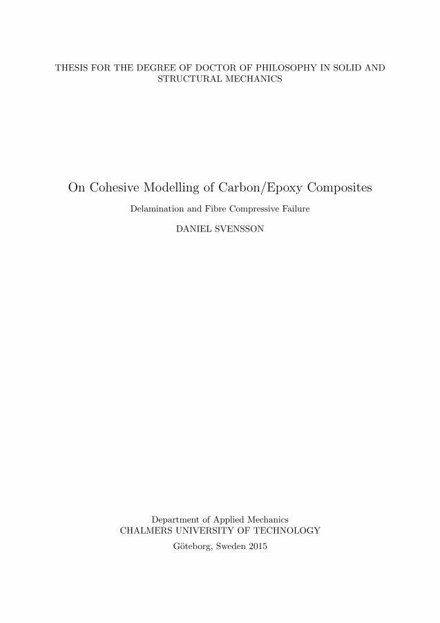
Improved mechanical performance and weight reduction are the driving forces for theincreasing usage of advanced composite materials in structural applications. CarbonFibre Reinforced Polymers (CFRP) combine strong and stiff carbon fibres with a loadtransferring and protective polymer matrix material. The CFRP:s considered in this thesisare continuous fibre composites sometimes called long fibre composites. A laminatedCFRP is schematically sketched in Fig. 1.1. Plies, also referred to as laminae, are thinlayers consisting of the two basic constituents, i.e. aligned carbon fibres and the polymermatrix. The laminate is built up by stacking plies of varying fibre orientations.
θ = fibre orientation
LaminateLaminae/plies fibre
Matrix y
xz
Figure 1.1: Schematic sketch of a laminated CFRP. Picture re-drawn from [1].
The main advantage of CFRP is their excellent specific stiffness and strength in the x-y-plane. When tailoring fibre orientations efficiently, considerably higher specific stiffnessand strength are achieved than for traditional engineering materials, e.g. steel andaluminium. Mainly due to the weight saving potential, CFRP:s are heavily utilized inmany engineering fields and products, e.g. aeronautical, aerospace, naval, wind energy,automotive, sport equipment and a wide range of civil constructions, e.g. pipes andreinforcement of bridges. The aeronautical industry can be considered to be leading theaggressive development towards an extended use of CFRP and other advanced compositematerials. At the early stages, this development was mainly driven by the military industrybut has lately been overtaken by the civil aircraft industry to counter the rising fuel prices,environmental impact and the desire to enhance the range/payload ratio. Besides thehigh specific mechanical properties, the superior resistance to corrosion and fatigue arevery beneficial. This enables longer inspection intervals that decreases the maintenancecost [2]. The usage of advanced composite materials in commercial aircrafts has increasedrapidly the last decade. An example of this is the Boeing 787 Dreamliner aircraft, thatcomprises CFRP and other composite materials to about 50 % of the material weight, cf.Fig. 1.2.
2
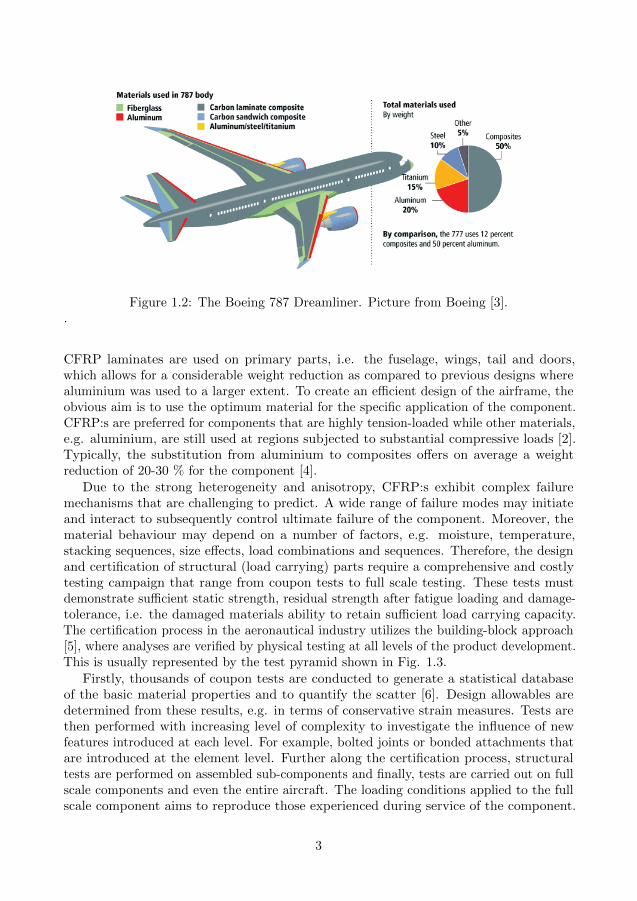
Figure 1.2: The Boeing 787 Dreamliner. Picture from Boeing [3]..
CFRP laminates are used on primary parts, i.e. the fuselage, wings, tail and doors,which allows for a considerable weight reduction as compared to previous designs wherealuminium was used to a larger extent. To create an efficient design of the airframe, theobvious aim is to use the optimum material for the specific application of the component.CFRP:s are preferred for components that are highly tension-loaded while other materials,e.g. aluminium, are still used at regions subjected to substantial compressive loads [2].Typically, the substitution from aluminium to composites offers on average a weightreduction of 20-30 % for the component [4].
Due to the strong heterogeneity and anisotropy, CFRP:s exhibit complex failuremechanisms that are challenging to predict. A wide range of failure modes may initiateand interact to subsequently control ultimate failure of the component. Moreover, thematerial behaviour may depend on a number of factors, e.g. moisture, temperature,stacking sequences, size effects, load combinations and sequences. Therefore, the designand certification of structural (load carrying) parts require a comprehensive and costlytesting campaign that range from coupon tests to full scale testing. These tests mustdemonstrate sufficient static strength, residual strength after fatigue loading and damage-tolerance, i.e. the damaged materials ability to retain sufficient load carrying capacity.The certification process in the aeronautical industry utilizes the building-block approach[5], where analyses are verified by physical testing at all levels of the product development.This is usually represented by the test pyramid shown in Fig. 1.3.
Firstly, thousands of coupon tests are conducted to generate a statistical databaseof the basic material properties and to quantify the scatter [6]. Design allowables aredetermined from these results, e.g. in terms of conservative strain measures. Tests arethen performed with increasing level of complexity to investigate the influence of newfeatures introduced at each level. For example, bolted joints or bonded attachments thatare introduced at the element level. Further along the certification process, structuraltests are performed on assembled sub-components and finally, tests are carried out on fullscale components and even the entire aircraft. The loading conditions applied to the fullscale component aims to reproduce those experienced during service of the component.
3

For example, in the certification of the complete wing of a Boeing 787, the wing wasbended upwards beyond the ultimate load to demonstrate its safe design [6].
Figure 1.3: Test pyramid illustrating the different complexity levels in the certificationprogram. Picture: courtesy of professor Tonny Nyman, SAAB Aeronautics/Royal Instituteof Technology, Sweden.
To account for the presence of damage, damage-tolerance of the composite structureneeds to be demonstrated for more built up structures. Defects may be present fromthe manufacturing process or arise during harsh working conditions such as impactloads. Within the damage-tolerance concept, it is required that defects have no-growthcharacteristics or do not grow to critical size depending on the severity of the defect.Defects on the threshold of detectability, i.e. barely visible damage, must display no-growth characteristics, i.e. they will not grow under normal working conditions. In thedesign phase, the presence of such defects is often accounted for in the model or test byincluding an equivalent artificial defect of comparable size [7].
Due to the large cost and time consumption associated with the testing campaign, itis desirable to increase the analysis capability in order to replace parts of the physicaltests with virtual tests. The associated cost of an individual test increases rapidly asthe complexity level increases. However, it is anticipated that full-scale testing will berequired for the certification of aircrafts also in the future. The primary goal is therefore toreplace tests at the intermediate complexity levels by virtual testing [8]. Thus, within theresearch community, there is a driving force to formulate analytical and numerical modelsthat enable accurate prediction of damage growth and subsequent failure of composites.
Stress based models may often be used to predict initiation of damage and, undersome circumstances, even to predict failure. However, critical regions are often locatedat material and geometrical discontinuities where singular stresses are predicted which
4
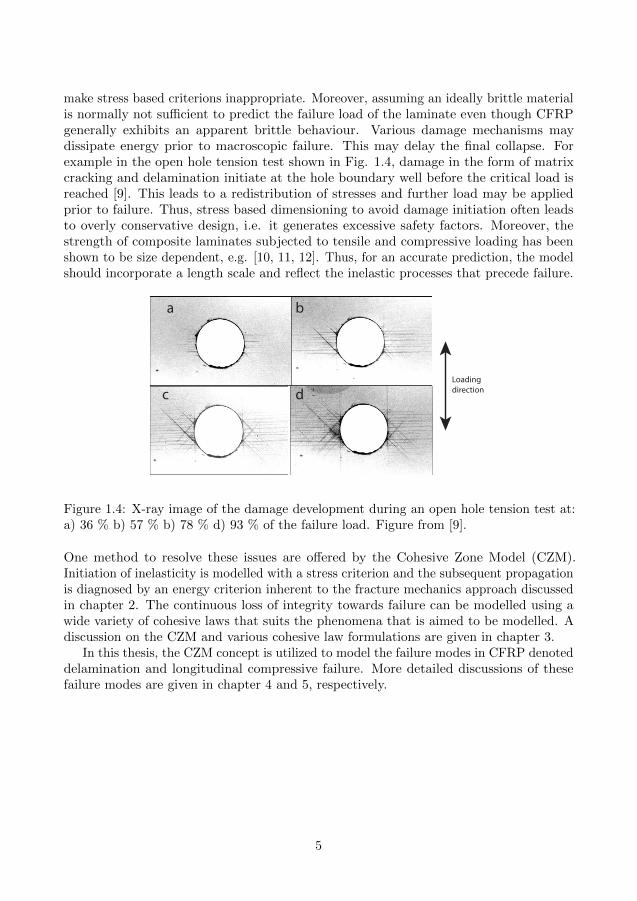
make stress based criterions inappropriate. Moreover, assuming an ideally brittle materialis normally not sufficient to predict the failure load of the laminate even though CFRPgenerally exhibits an apparent brittle behaviour. Various damage mechanisms maydissipate energy prior to macroscopic failure. This may delay the final collapse. Forexample in the open hole tension test shown in Fig. 1.4, damage in the form of matrixcracking and delamination initiate at the hole boundary well before the critical load isreached [9]. This leads to a redistribution of stresses and further load may be appliedprior to failure. Thus, stress based dimensioning to avoid damage initiation often leadsto overly conservative design, i.e. it generates excessive safety factors. Moreover, thestrength of composite laminates subjected to tensile and compressive loading has beenshown to be size dependent, e.g. [10, 11, 12]. Thus, for an accurate prediction, the modelshould incorporate a length scale and reflect the inelastic processes that precede failure.
a b
c dLoading direction
Figure 1.4: X-ray image of the damage development during an open hole tension test at:a) 36 % b) 57 % b) 78 % d) 93 % of the failure load. Figure from [9].
One method to resolve these issues are offered by the Cohesive Zone Model (CZM).Initiation of inelasticity is modelled with a stress criterion and the subsequent propagationis diagnosed by an energy criterion inherent to the fracture mechanics approach discussedin chapter 2. The continuous loss of integrity towards failure can be modelled using awide variety of cohesive laws that suits the phenomena that is aimed to be modelled. Adiscussion on the CZM and various cohesive law formulations are given in chapter 3.
In this thesis, the CZM concept is utilized to model the failure modes in CFRP denoteddelamination and longitudinal compressive failure. More detailed discussions of thesefailure modes are given in chapter 4 and 5, respectively.
5
1.2 Types of CFRP materials in this thesis
Two different types of CFRP:s are used for the studies in this thesis. In papers A-B,experiments are conducted on a pre-impregnated tape material often abbreviated asprepreg materials. In paper D, a material is studied that is characterised as a Non-CrimpFabric (NCF) composite. A detailed discussion on NCF:s is given in [13]. Common forboth materials is the clear laminated structure with distinct plies of aligned carbon fibresas schematically illustrated in Fig. 1.1.
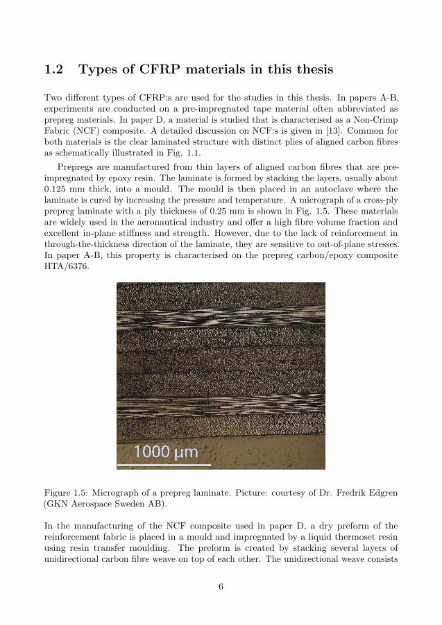
Prepregs are manufactured from thin layers of aligned carbon fibres that are pre-impregnated by epoxy resin. The laminate is formed by stacking the layers, usually about0.125 mm thick, into a mould. The mould is then placed in an autoclave where thelaminate is cured by increasing the pressure and temperature. A micrograph of a cross-plyprepreg laminate with a ply thickness of 0.25 mm is shown in Fig. 1.5. These materialsare widely used in the aeronautical industry and offer a high fibre volume fraction andexcellent in-plane stiffness and strength. However, due to the lack of reinforcement inthrough-the-thickness direction of the laminate, they are sensitive to out-of-plane stresses.In paper A-B, this property is characterised on the prepreg carbon/epoxy compositeHTA/6376.
Figure 1.5: Micrograph of a prepreg laminate. Picture: courtesy of Dr. Fredrik Edgren(GKN Aerospace Sweden AB).
In the manufacturing of the NCF composite used in paper D, a dry preform of thereinforcement fabric is placed in a mould and impregnated by a liquid thermoset resinusing resin transfer moulding. The preform is created by stacking several layers ofunidirectional carbon fibre weave on top of each other. The unidirectional weave consists
6
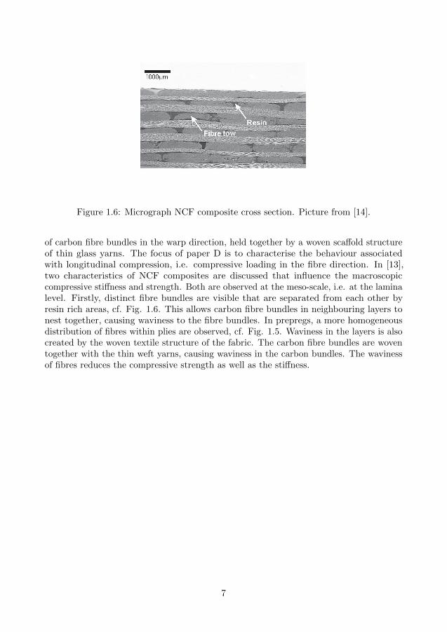
Figure 1.6: Micrograph NCF composite cross section. Picture from [14].
of carbon fibre bundles in the warp direction, held together by a woven scaffold structureof thin glass yarns. The focus of paper D is to characterise the behaviour associatedwith longitudinal compression, i.e. compressive loading in the fibre direction. In [13],two characteristics of NCF composites are discussed that influence the macroscopiccompressive stiffness and strength. Both are observed at the meso-scale, i.e. at the laminalevel. Firstly, distinct fibre bundles are visible that are separated from each other byresin rich areas, cf. Fig. 1.6. This allows carbon fibre bundles in neighbouring layers tonest together, causing waviness to the fibre bundles. In prepregs, a more homogeneousdistribution of fibres within plies are observed, cf. Fig. 1.5. Waviness in the layers is alsocreated by the woven textile structure of the fabric. The carbon fibre bundles are woventogether with the thin weft yarns, causing waviness in the carbon bundles. The wavinessof fibres reduces the compressive strength as well as the stiffness.
7

1.3 Failure modes in CFRP
In the fracture process of CFRP laminates, several failures modes usually occur andinteract in a complex manner. The extent of each failure mode may vary from ply to plydepending on, e.g. the loading conditions and stacking sequence. The major failure modesare divided into three groups to facilitate the discussion in the following sections. Thethree groups denoted interlaminar, intralaminar and translaminar failures are depicted inFig. 1.7 [15].
Figure 1.7: Illustration of the major failure modes in CFRP. Picture from [15].
Ply
Ply
Delamination
Broken �bres
Figure 1.8: Left : Schematic sketch of delaminated plies. Right : Schematic sketch of akink-band.
Interlaminar failure also referred to as delamination corresponds to fracture throughseparation of adjacent plies as depicted in Fig. 1.8a. Delamination is discussed indetail in chapter 4. Intralaminar failure corresponds to matrix cracking and matrix/fibredebonding within plies. Longitudinal intralaminar cracking is also referred to as splitting.Translaminar failures are fibre dominated failures and refer to tensile or compressive
8
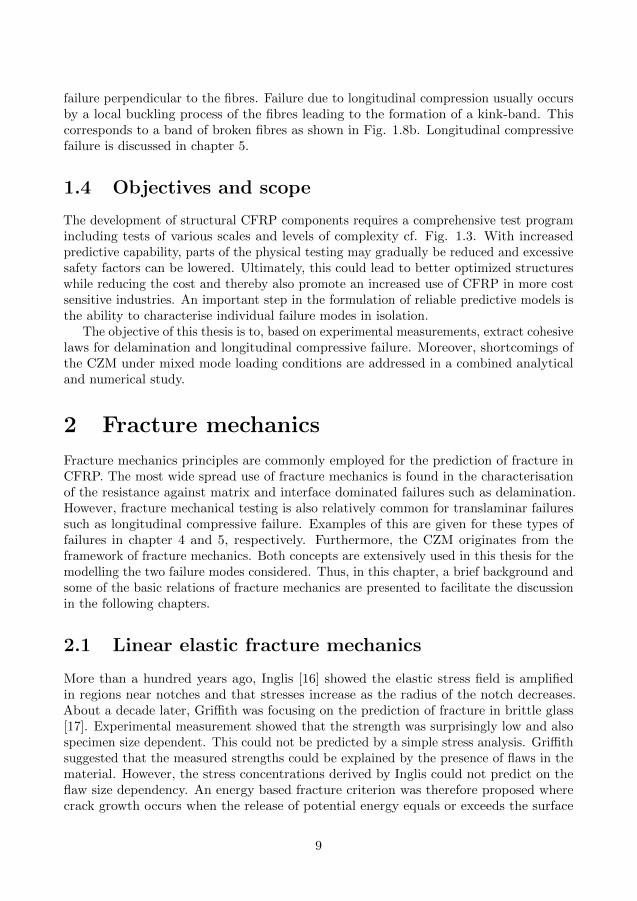
failure perpendicular to the fibres. Failure due to longitudinal compression usually occursby a local buckling process of the fibres leading to the formation of a kink-band. Thiscorresponds to a band of broken fibres as shown in Fig. 1.8b. Longitudinal compressivefailure is discussed in chapter 5.
1.4 Objectives and scope
The development of structural CFRP components requires a comprehensive test programincluding tests of various scales and levels of complexity cf. Fig. 1.3. With increasedpredictive capability, parts of the physical testing may gradually be reduced and excessivesafety factors can be lowered. Ultimately, this could lead to better optimized structureswhile reducing the cost and thereby also promote an increased use of CFRP in more costsensitive industries. An important step in the formulation of reliable predictive models isthe ability to characterise individual failure modes in isolation.
The objective of this thesis is to, based on experimental measurements, extract cohesivelaws for delamination and longitudinal compressive failure. Moreover, shortcomings ofthe CZM under mixed mode loading conditions are addressed in a combined analyticaland numerical study.
2 Fracture mechanics
Fracture mechanics principles are commonly employed for the prediction of fracture inCFRP. The most wide spread use of fracture mechanics is found in the characterisationof the resistance against matrix and interface dominated failures such as delamination.However, fracture mechanical testing is also relatively common for translaminar failuressuch as longitudinal compressive failure. Examples of this are given for these types offailures in chapter 4 and 5, respectively. Furthermore, the CZM originates from theframework of fracture mechanics. Both concepts are extensively used in this thesis for themodelling the two failure modes considered. Thus, in this chapter, a brief background andsome of the basic relations of fracture mechanics are presented to facilitate the discussionin the following chapters.
2.1 Linear elastic fracture mechanics
More than a hundred years ago, Inglis [16] showed the elastic stress field is amplifiedin regions near notches and that stresses increase as the radius of the notch decreases.About a decade later, Griffith was focusing on the prediction of fracture in brittle glass[17]. Experimental measurement showed that the strength was surprisingly low and alsospecimen size dependent. This could not be predicted by a simple stress analysis. Griffithsuggested that the measured strengths could be explained by the presence of flaws in thematerial. However, the stress concentrations derived by Inglis could not predict on theflaw size dependency. An energy based fracture criterion was therefore proposed wherecrack growth occurs when the release of potential energy equals or exceeds the surface
9
energy required to create new crack surfaces. This release of potential energy per unitarea is known as the energy release rate, G, sometimes referred to as the crack drivingforce. That is, with Π and a denoting the potential energy per unit width and the cracklength, respectively, G is defined by
G = −dΠ
da. (2.1)
With this approach, Griffith was able to accurately predict the strength versus flaw size.However, the method was not applicable for metals and thereby not useful in manyfields of engineering. Irwin extended Griffith’s work of the energy release rate conceptsuch that crack growth in metals could be predicted [18]. He noticed that the increasedsurface energy during fracture of metals is in principal negligible compared to the energydissipated by the plastic deformation near the crack tip. Moreover, Irwin also found thatG was related to the singular stress field in the vicinity of the crack tip. The amplitudeof the singular stress was shown to scale with one parameter that is directly related to G,i.e. the stress intensity factor, K.
In the Linear Elastic Fracture Mechanics (LEFM) approach, crack growth is predictedwhen G or K reaches its critical value and the two formulations are completely equivalent.The critical values denoted the fracture energy Gc and the fracture toughness Kc, respec-tively, specify the material’s resistance to fracture and are considered to be properties ofthe material.
The stress intensity factor and its components are given by solving a linear elasticboundary-value problem and depend on the loading and geometry of the specimen. Acollection of stress intensity factors for various geometries and isotropic material are givenin [19]. In [20], Sou et al. develops a rescaling technique where approximate stress intensityfactors and stress concentration factors for orthotropic materials may be constructed fromthe isotropic case. This is exemplified by Bao et al. [21] for several test geometries.
Mode I: Opening
Mode II: In-plane shear
Mode III: Anti-plane shear
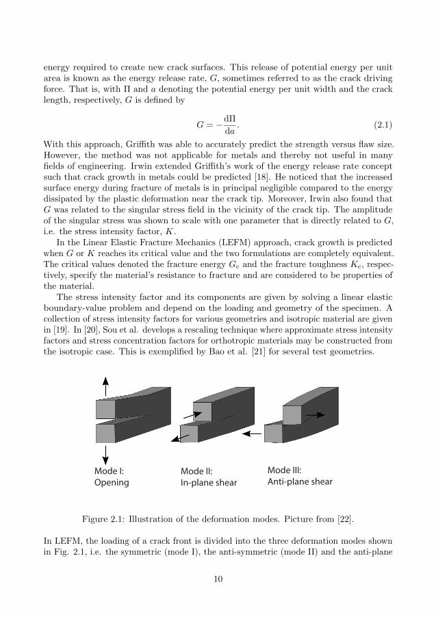
Figure 2.1: Illustration of the deformation modes. Picture from [22].
In LEFM, the loading of a crack front is divided into the three deformation modes shownin Fig. 2.1, i.e. the symmetric (mode I), the anti-symmetric (mode II) and the anti-plane
10
(mode III) part of loading. In this thesis, the discussion is restricted mode I and modeII. When LEFM applies the body can be analysed assuming linear elasticity. Thus, themodes of loading of the crack tip can be treated independently by superposition. That is,K and G may be divided into components associated with respective mode of loading, i.e.
G = GI +GII K = KI +KII. (2.2)
For isotropic materials, K and G are related by GI = K2I /E and GII = K2
II/E whereE = E for plane stress and E = E/(1 − ν2) for plane strain. Similar relations foranisotropic materials were derived by Sih et al. in [23]. This is discussed later in thissection.
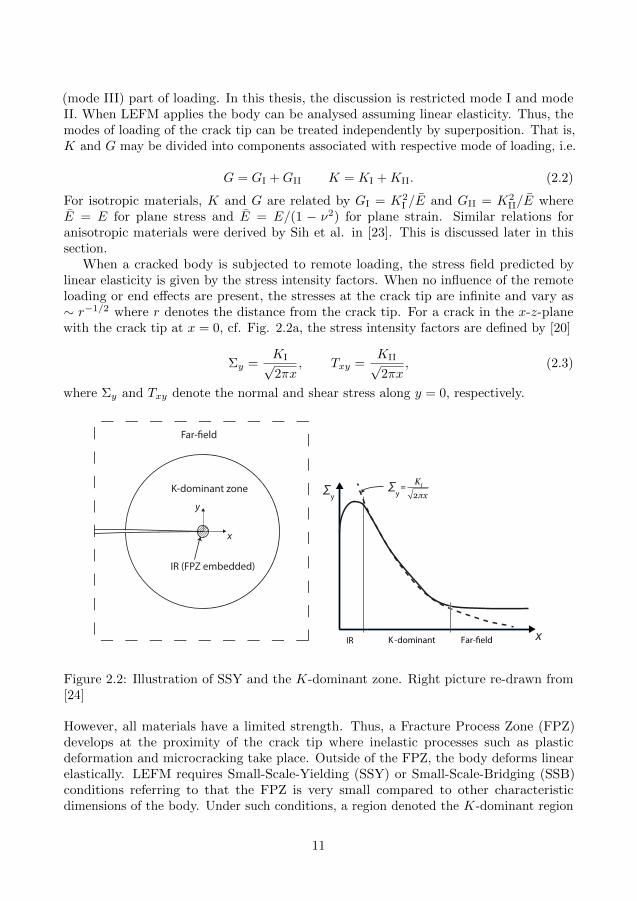
When a cracked body is subjected to remote loading, the stress field predicted bylinear elasticity is given by the stress intensity factors. When no influence of the remoteloading or end effects are present, the stresses at the crack tip are infinite and vary as∼ r−1/2 where r denotes the distance from the crack tip. For a crack in the x-z-planewith the crack tip at x = 0, cf. Fig. 2.2a, the stress intensity factors are defined by [20]
Σy =KI√2πx
, Txy =KII√2πx
, (2.3)
where Σy and Txy denote the normal and shear stress along y = 0, respectively.
IR (FPZ embedded)
K-dominant zone
Far-�eld
x
y
= KI
2 x
IR K-dominant Far-�eld
Σy
x
Σy
Figure 2.2: Illustration of SSY and the K-dominant zone. Right picture re-drawn from[24]
However, all materials have a limited strength. Thus, a Fracture Process Zone (FPZ)develops at the proximity of the crack tip where inelastic processes such as plasticdeformation and microcracking take place. Outside of the FPZ, the body deforms linearelastically. LEFM requires Small-Scale-Yielding (SSY) or Small-Scale-Bridging (SSB)conditions referring to that the FPZ is very small compared to other characteristicdimensions of the body. Under such conditions, a region denoted the K-dominant region
11

exists. In this region, stresses and displacements are governed by the linear elastic solution,i.e. by the components of K. That is, within this zone, stresses and displacements obeythe singular elastic field and are not influenced by the FPZ or boundary effects. Thisis illustrated in Fig. 2.2a, where three regions are indicated, i.e. the Influenced Region(IR), the K-dominant region and the far-field. The IR region contains the FPZ andadjacent elastically deforming points that are influenced by the FPZ. That is, the FPZ isembedded in the IR as shown in Fig. 2.2a. As shown, the extension of the K-dominantzone is limited by the far-field where the stresses and displacements are influenced byouter boundaries and remote loading. In Fig. 2.2b, the normal stress distribution aheadof the crack tip under SSY conditions is schematically sketched with a solid line and thesingular stress field is indicated by dashed line.
The elastic stress, strain and displacement fields for an orthotropic material areformulated by Sih et al. in [23]. In [20], Sou et al. introduce two dimensionlessparameters that fully characterise the orthotropy and thereby reduce the number ofmaterial parameters,
λ =s11s22
, ρ =2s12 + s662√s11s22
, (2.4)
where sij are the plane stress or the plane strain orthotropic compliances given in [25].More specifically, with the generalized Hooke’s law1
εi =∑
j
sijσj . (2.5)
For plane stress conditions, the relevant components of sij for λ and ρ are,
s11 =1
E1, s22 =
1
E2, s66 =
1
G12, s12 = −ν12
E1= −ν21
E2, (2.6)
where subscript 1 and 2 denote components in the x- and y-direction that coincide withthe principal axes of the orthotropic material. Here, Ei is the Young’s modulus in thei−direction, G12 is the shear modulus and νij are the Poisson’s ratios. For plane strainconditions, s′ij replace sij in Eqs. (2.4)-(2.5) [20]
s′ij = sij − si3sj3/s33. (2.7)
Sou et al. showed that K and G for orthotropic materials can be approximated fromisotropic solutions. For a crack along the x-direction, the λ-dependence can be derivedexplicitly by rescaling the x-axis by ξ = λ1/4x. Thus, the calibration of G and K fordifferent geometries depend on one material parameter only, i.e. ρ. In [21], Bao et al.calibrated this dependence with polynomials for several test specimens by numericalinvestigations using finite element analyses.
For plane stress, the relations between the energy release rates and stress intensityfactors are in [23] given by
GI =
(s11s22
1 + ρ
2
)1/2
λ−1/4K2I , GII =
(s11s22
1 + ρ
2
)1/2
λ1/4K2II. (2.8)
1Voight notation is adopted, i.e. ε1 = εx, ε2 = εy , ..., ε6 = γxy and σ1 = σx, σ2 = σy , ..., σ6 = τxy .
12
For plane strain conditions, s′ij replace sij in Eqs. (2.4) and (2.8).
In the formulation of G for a specific test specimen, one may derive the expressionfor K as discussed above and obtain G with Eq. (2.8). Fracture mechanical testingwith the assumption of LEFM is often carried out on beam-like geometries, especiallyin characterisation of delamination resistance of CFRP. In such situations, the ERR isusually derived by the compliance method assuming beam theory. With this approachone may utilize the general expression, cf. e.g. [26]
G = −dΠ
da=P 2
b
dC
da, (2.9)
where P , b, a and C are the applied load, specimen width, crack length and compliancerespectively. With C expressed in terms of a, G may be formulated as a function ofthe applied load, the displacement of the loading point or a combination of thereof. Ifsimple beam theory is used, correction factors are needed to account for orthotropy or thepresence of a non-negligible shear force that complicate the deformation close to the cracktip. Such correction factors are given in [21] and in [27] several proposed formulations areexamined for delamination testing of CFRP.
A third option for the derivation of the ERR is to utilize the J-integral [28]. This is avery useful tool since the assumption of SSY conditions is not required.
2.2 The J-integral
In the late 1960’s, Rice introduced a line integral denoted the J-integral for the character-isation of the local deformation field near cracks, notches and other stress raising featuresin two-dimensional problems [28]. A severe difficulty to determine such deformation fieldswas identified, especially when the material around the notch-tip undergoes substantialnon-linear deformation. By using the fact that the J-integral under favourable circum-stances is integration path independent, Rice bypassed this difficulty. That is, the localdeformation field near the notch-tip can be determined by studying the stress, strainand displacement field far away from the notch-tip that is sometimes straight forward toderive.
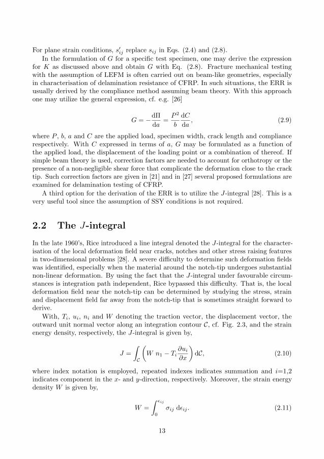
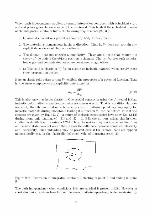
With, Ti, ui, ni and W denoting the traction vector, the displacement vector, theoutward unit normal vector along an integration contour C, cf. Fig. 2.3, and the strainenergy density, respectively, the J-integral is given by,
J =
∫
C
(W n1 − Ti
∂ui∂x
)dC, (2.10)
where index notation is employed, repeated indexes indicates summation and i=1,2indicates component in the x- and y-direction, respectively. Moreover, the strain energydensity W is given by,
W =
∫ εij
0
σij dεij . (2.11)
13
When path independency applies, alternate integration contours, with coincident startand end points gives the same value of the J-integral. This holds if the embedded domainof the integration contours fulfils the following requirements [29, 30]:
1. Quasi-static conditions prevail without any body forces present.
2. The material is homogenous in the x-direction. That is, W does not contain anyexplicit dependence of the x−coordinate.
3. The domain does not encircle a singularity. These are objects that change theenergy of the body if the objects position is changed. That is, features such as holes,free edges and concentrated loads are considered singularities.
4. a) The solid is elastic or b) for an elastic or inelastic material when steady statecrack propagation occurs.
Here an elastic solid refers to that W exhibits the properties of a potential function. Thatis, the stress components are explicitly determined by,
σij =∂W
∂εij. (2.12)
This is also known as hyper-elasticity. One central concept in using the J-integral is thatinelastic deformation is analysed as being non-linear elastic. That is, condition 4a doesnot imply that the material must be strictly elastic. Path-independency may apply forinelastic materials during monotonic loading if a function W can be defined so that thestresses are given by Eq. (2.12). A range of inelastic constitutive laws obey Eq. (2.12)during monotonic loading, cf. [31] and [32]. In [33], the authors utilize this in theirstudies on ductile fracture using a CZM. Thus, the method requires that unloading froman inelastic state does not occur that reveals the difference between non-linear elasticityand inelasticity. Such unloading may be present even if the remote loads are appliedmonotonically, e.g. in the plastically deformed wake of a growing crack [33].
Figure 2.3: Illustration of integration contour, C starting in point A and ending in pointB.
The path independency when conditions 1-4a are satisfied is proved in [28]. However, ashort discussion is given here for completeness. Path-independency is demonstrated by
14
showing that the J-integral is zero when evaluated along any closed integration path, C,that does not encircle any singularity. Equation (2.10) is converted to an area integral byusing Cauchy’s relation Ti = σijnj and employing the divergence theorem,
J =
∫
A
(∂W
∂x− ∂
∂xj
(σij
∂ui∂x
))dxdy, (2.13)
where A denotes the domain embedded by the closed contour C. By utilizing a combinationof basic continuum mechanical relations, it is shown that the integrand vanishes ifconditions 1-4a are satisfied. With the assumption that conditions 2 and 4a are fulfilled,i.e. Eq. (2.12) holds, the first equality is obtained
∂W
∂x=∂W
∂εij
∂εij∂x
= σij1
2
(∂
∂x
∂ui∂xj
+∂
∂x
∂uj∂xi
)= σij
∂
∂xj
(∂ui∂x
). (2.14)
The second equality is obtained by using the strain-displacement relation, i.e. εij =(∂ui/∂xj + ∂uj/∂xi)/2, from which the right hand side is obtained by utilizing symmetryof the stress tensor, i.e. σij = σji. Finally, by utilizing static equilibrium σij,j = 0, i.e.assuming condition 1, σij can be moved inside the parenthesis. Thus, the integrand of Eq.(2.13) vanishes if conditions 1-4a prevail and the path-independency is shown.
When integration path independency applies, the J-integral evaluated along an arbi-trary contour around a crack tip gives the ERR [30]. More specifically, with an arbitraryintegration contour that starts in point A and ends in point B as indicated in Fig. 2.3and the x-direction denoting the orientation of the crack, then G = J . In this extendedsummary, G denotes the ERR with no assumption of applicability of LEFM in line with[30, 29]. In situations when the LEFM assumption is inappropriate Eqs. (2.2, 2.8, 2.9)are not valid2. However, in [30], it is shown that although the J-integral is generally pathdependent if conditions 1-4 are violated, the J-integral is equal to G when C is confinedto the crack tip, i.e.
G = JC when C → 0 (2.15)
where, JC denotes the value of J evaluated along an integration path C shrunk to thecrack tip.
The fact that the J-integral gives the ERR is shown in [30] both for the case whenpath-independency applies and is violated. For the latter case, this result is demonstratedfor an integration path C confined to the crack tip as stated in Eq. (2.15). However, whenconditions 1-4a are fulfilled this may be demonstrated using a similar set of equations asused for the proof presented above. This is derived in detail in [34] and the main steps ispresented here.
In quasi-static conditions with no body forces present, the potential energy per unitwidth of the body is given by.
Π =
∫
A
WdA−∫
CTiuidC, (2.16)
2In paper C, an additional variable G is introduced that denotes the ERR obtained from the localfield. This is done to differ between the ERR and the apparent ERR obtained from the external loadsassuming that LEFM applies.
15
where A and C is the area and the outer boundary of the domain. Then the change ofpotential energy due to a virtual extension of the crack tip becomes,
dΠ
da=
∫
A
dW
dadA−
∫
CTi
duida
dC (2.17)
By attaching the coordinate system to the crack tip one obtains,
d
da=
∂
∂a+∂x
∂a
∂
∂x=
∂
∂a− ∂
∂x(2.18)
since ∂x/∂a = −1. Thus, Eq (2.17) is reformulated as,
dΠ
da=
∫
A
(∂W
∂a− ∂W
∂x
)dA−
∫
CTi
(∂ui∂a− ∂ui∂x
)dC (2.19)
If conditions 2 and 4a is fulfilled then, analogous to Eq. (2.14), the first term of the firstintegrand can be formulated as
∂W
∂a=∂W
∂εij
∂εij∂a
= σij∂
∂xj
(∂ui∂a
). (2.20)
By the divergence theorem, the first term of the first integral cancels out the first term ofthe second integral in Eq (2.19). Thus, the remaining of Eq (2.19) reads:
dΠ
da=
∫
CTi∂ui∂x
dC −∫
A
∂W
∂xdA (2.21)
By using the divergence theorem on the second term we obtain,
−dΠ
da=
∫
C
(Wdy − Ti
∂ui∂x
dC), (2.22)
Thus, when conditions 1-4a are fulfilled, the J-integral evaluated around the crack tip isequal to the energy release rate, G.
The J-integral is a key concept in the cohesive modelling of fracture. Moreover, theconditions for path-independency of the J-integral requires special attention when mixedmode fracture is studied using the CZM. These topics are further discussed in section 3.2.
3 The cohesive zone model
In a LEFM analysis of crack growth, the FPZ is idealized to a mathematical point at thecrack tip. Thus, LEFM is suitable when fracture is to be analysed from a pre-existingcrack and the size of the FPZ is negligible in comparison with other geometric lengthscales. However, in other situations a more complete model of the fracture process isrequired that reflects the nonlinear mechanisms within the FPZ. A candidate to achievethis is offered by the CZM. All inelastic mechanisms acting within the FPZ are lumpedinto a surface in a 3D analysis or a line in a 2D analysis denoted the cohesive zone in the
16
Cohesive zone
FPZ
T
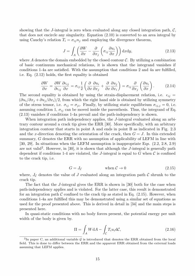
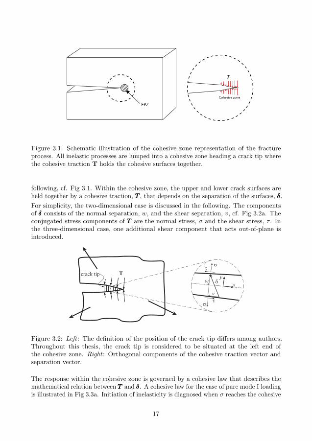
Figure 3.1: Schematic illustration of the cohesive zone representation of the fractureprocess. All inelastic processes are lumped into a cohesive zone heading a crack tip wherethe cohesive traction T holds the cohesive surfaces together.
following, cf. Fig 3.1. Within the cohesive zone, the upper and lower crack surfaces areheld together by a cohesive traction, TTT , that depends on the separation of the surfaces, δδδ.
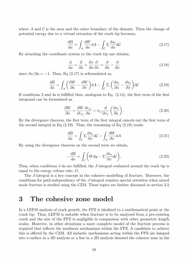
For simplicity, the two-dimensional case is discussed in the following. The componentsof δδδ consists of the normal separation, w, and the shear separation, v, cf. Fig 3.2a. Theconjugated stress components of TTT are the normal stress, σ and the shear stress, τ . Inthe three-dimensional case, one additional shear component that acts out-of-plane isintroduced.
Tcrack tip
s
st
t
v
w dx
y
Figure 3.2: Left : The definition of the position of the crack tip differs among authors.Throughout this thesis, the crack tip is considered to be situated at the left end ofthe cohesive zone. Right : Orthogonal components of the cohesive traction vector andseparation vector.
The response within the cohesive zone is governed by a cohesive law that describes themathematical relation between TTT and δδδ. A cohesive law for the case of pure mode I loadingis illustrated in Fig 3.3a. Initiation of inelasticity is diagnosed when σ reaches the cohesive
17
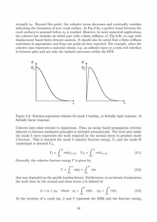
strength σ0. Beyond this point, the cohesive stress decreases and eventually vanishesindicating the formation of new crack surface. In Fig 3.3a, a perfect bond between thecrack surfaces is assumed before σ0 is reached. However, in most numerical applications,the cohesive law includes an initial part with a finite stiffness, cf. Fig 3.3b, to cope withdisplacement based finite element analysis. It should also be noted that a finite stiffnesssometimes is appropriate and from one point-of-view expected. For example, when thecohesive zone represents a material volume, e.g. an adhesive layer or a resin rich interfacein-between plies and not only the inelastic processes within the FPZ.
σσσ0σ0
w w
Figure 3.3: Traction-separation relation for mode I loading. a) Initially rigid response. b)Initially linear response.
Cohesive laws relate stresses to separations. Thus, an energy based propagation criterioninherent to fracture mechanics principles is included automatically. The total area underthe mode I curve represents the work required by the normal stress to produce modeI fracture. This is denoted the mode I cohesive fracture energy, ΓI and the mode IIcounterpart is denoted ΓII,
ΓI =
∫ ∞
0
σdw|v=0, ΓII =
∫ ∞
0
τdv|w=0 (3.1)
Generally, the cohesive fracture energy Γ is given by,
Γ =
∫ ∞
0
σdw +
∫ ∞
0
τdv (3.2)
that may depended on the specific loading history. Furthermore, at an instant of separation,the work done by the normal and shear stress φ is defined by
φ = φI + φII where φI =
∫ w
0
σdw, φII =
∫ v
0
τdv, (3.3)
At the location of a crack tip, φ and Γ represent the ERR and the fracture energy,
18
respectively. Some aspects on the formulation of the evolution of φ during monotonicmixed mode loading are discussed in section 3.1.
As pointed out and exemplified in [35], a major benefit of the CZM is the wide rangeof applicability. This is enabled since the CZM incorporates both a damage initiationcriterion and an energy based propagation criterion. Stress-based models are inappropriatewhen fracture emerges from the location of a stress singularity and LEFM based methodsrequires an initial crack. These two restrictions are by-passed with the CZM. Thus, theCZM may be successfully calibrated to model fracture in situations where stress-basedmodels or LEFM-based methods or possible both may be invalid. A more detaileddiscussion of this is given in section 3.3.
The CZM:s used today stems from the pioneering work of Barenblatt [36] and Dugdale[37]. The introduction of cohesive forces acting ahead of the crack was mainly motivatedby the desire to remove the crack tip singularity given by an elastic stress analysis.Barenblatt was focusing on the analysis of the fracture process in a perfectly brittlematerial by relating the crack resistance to the interatomic binding energy. The cohesiveforces between the crack surfaces were assumed to be acting within a small region ahead ofthe crack tip. Dugdale was using a CZM denoted the strip yield model where the cohesivestress is constant within the complete cohesive zone to estimate the plastic zone size inmetals near the crack tip. Later, a CZM known as the fictitious crack model developedby Hillerborg was used to study crack growth in concrete [38]. This model was used as aconstitutive property of concrete and was an important extension of the previous work in[36, 37] since a crack was allowed to nucleate and propagate anywhere in the material.Thus, prediction of fracture in initially virgin materials was enabled.
The CZM was first introduced in a finite element context by Needleman [39] to studyvoid nucleation between particles and matrix. Since then, cohesive finite elements havebeen used to predict fracture in e.g. adhesively bonded joints [40], metals [33] and bi-material interfaces [41]. Delamination in CFRP was first modelled using cohesive elementsin the early 1990’s, cf. [42, 43, 44]. In addition to delamination problems, cohesiveelements have been used to model a variety of failure modes in CFRP at different lengthscales ranging from debonding of fibre and matrix to macroscopic in-plane failure, cf.the relatively recent review given by Wisnom [35]. Cohesive elements were implementedin version 6.5 of Abaqus and are nowadays available in most commercial finite elementsoftwares.
A drawback with modelling crack growth using traditional cohesive elements is thatthe crack path must be specified beforehand. However, for e.g. delamination of laminatedcomposites this is not a severe limitation since the crack propagation is restricted to theinterfaces between plies [35].
It should however be noted that delamination propagation in CFRP often occurs withsome kind of toughening mechanism present, usually in the form of cross-over fibres inthe wake of the crack. The increasing resistance during crack growth can be reflected bythe cohesive law, cf. [45].
19
3.1 Types of cohesive laws
Since the introduction of the CZM into FE-codes, numerous cohesive law formulationshave been proposed. Most early cohesive law formulations were intended for predictingpure mode fracture or at least when one mode of deformation is very dominating over theother. Cohesive laws of varying softening responses may be categorised as polynomial [46],piece-wise linear [33], exponential [41] and rigid linear [47], cf. [48]. However, interfacefracture such as delamination in CFRP usually occurs under mixed mode conditions,cf. section 4.3. Although the mixed mode cohesive law formulations presented in theliterature differ in many aspects, especially one fundamental feature enables a separationof the cohesive laws into two groups: potential-based and non-potential-based cohesivelaws. In the continuation of this chapter, the discussion is restricted to monotonicallyincreasing separation of the cohesive zone.
Potential-based cohesive laws were first introduced by Needleman [39] and refers tocohesive laws that are derived from a potential function. That is, a function Φ (w, v)exists that acts as a potential to the cohesive stresses,
σ =∂Φ
∂wτ =
∂Φ
∂v. (3.4)
Integration of both expressions gives
∫ w
0
σdw = Φ(w, v) + I1(v)
∫ v
0
τdv = Φ(w, v) + I2(w). (3.5)
Thus, by identification of terms the potential function, Φ(w, v), is given by
Φ(w, v) =
∫ w
0
σdw +
∫ v
0
τdv, (3.6)
That is, Φ(w, v) is the accumulated area beneath the two curves σ − w and τ − v, i.e.Φ(w, v) = φ(w, v), cf. Eq (3.3). Thus, for potential-based cohesive laws, both the cohesivestresses, σ, τ , and work performed by the stresses, φ, are explicitly given by the currentstate of separation, i.e. independent of the previous separation history. Potential-basedcohesive laws are therefore often referred to as separation path independent cohesive laws.As discussed in [49], uncoupled laws, e.g. [50], constitute a subfamily of potential-basedcohesive laws. For such laws, the normal stress only depends on the normal separationand vice versa. That is, mixed mode fracture requires that both φI = ΓI and φII = ΓII
are reached unless a sudden loss of cohesive stress is enforced by the fracture criterion. Inpapers B-C, a special type of cohesive law is utilized for the modelling of mixed modefracture denoted initiation-driven cohesive law. For this cohesive law, the propertiesof the cohesive law are set by conditions at the crack tip at the onset of non-lineardeformation. This law exhibits the properties of a potential-based cohesive law duringmonotonic loading. However, the formulation depends on the conditions at onset ofnon-linear response and therefore cannot be described by Eq. 3.4.
A number of potential-based cohesive laws have been presented in the literature,e.g. [39, 51, 41, 52, 53, 54]. An important difference between these cohesive laws is
20
whether or not the cohesive fracture energy, Γ, is independent of the mode mix, e.g.[39, 51] or dependent on the mode mix, e.g. [41, 53]. The ability to calibrate a modedependent fracture criterion is important in the modelling of many interface fractures e.g.delamination, cf. section 4.3. However, it has been reported that potential-based cohesivelaws that allows for a mode dependent Γ may be associated with features that can beconsidered to be unphysical. In [55, 56], comprehensive reviews are given on this topic.For example, the authors notice repulsive normal stresses under mixed mode loading andthat mixed mode failure cannot be modelled by a simultaneous loss of normal and shearstress. In [48], similar results are reported for the commonly used cohesive law by Xu andNeedleman [41] when a mode dependent Γ is used.
Cohesive laws that are not formulated from a potential function, i.e. non-potential-based, are also frequently used in the literature. Such cohesive laws are often formulatedby explicit functions, σ(w, v) and τ(w, v), e.g. [57, 58, 59, 60, 48]. In [49], the authorsshow that these laws cannot in general be derived from a potential function unless veryrestricted conditions are fulfilled. That is, φ is generally depended on the loading history.These laws are referred to as stress-based cohesive laws in papers B-C.
Incremental cohesive laws based on plasticity and damage have also been presented,e.g. [61], where neither of σ, τ and φ are explicitly dependent on the state of separation.
3.2 Cohesive zones and the J-integral
The existence of a potential function that governs the cohesive law plays an importantrole in the cohesive modelling of fracture. This is realized by the derivation of G following[30, 29]. To this end, the J-integral is evaluated along a contour C confined to the cracktip as shown in Fig. 3.4,
G = limC→0JC =
∫
CW dy =
(∫ w
0
σdw +
∫ v
0
τdv
)
x=0
(3.7)
where the subscript x = 0 refers to the location of the crack tip. Applying Eq. (3.7) doesnot require the conditions for path-independency of the J-integral to be fulfilled, i.e. apotential-based cohesive law is not assumed. Thus, the work performed by the cohesivestresses at the crack tip, φtip, represent the ERR, cf. Eq. (3.3). This result was derivedin [45] and [62]. In [45], the authors evaluate the J-integral along an integration paththat encircles the cohesive zone, cf. Fig. 3.5. In that case, only the second term of theJ-integral is nonzero, cf. Eq. (2.10).
The major benefit of potential-based cohesive laws is that path-independency of theJ-integral may be applicable provided that the requirements are satisfied also for thesurrounding body of interest. This is illustrated in Fig. 3.6 where a fracture mechanicalspecimen with a cohesive zone assumed ahead of the crack tip is depicted. Evaluating theJ-integral close to the crack tip gives the right hand side of Eq. (3.7). With a cohesivezone governed by a potential and an elastic bulk, condition 4a stated in section 2.2 isfulfilled. Furthermore, if conditions 1-3 are fulfilled, then path-independency applies.Thus, all counter-clockwise integration contours about the crack tip give the same valueof J , i.e. the ERR. That is, there is a direct relation between the cohesive stresses acting
21
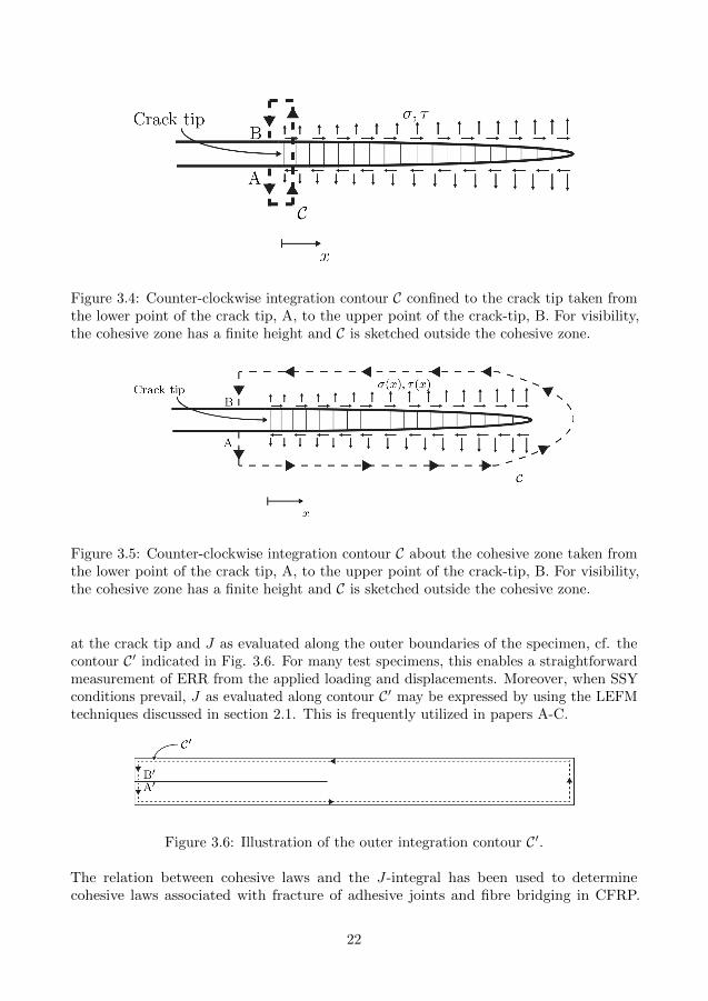
Figure 3.4: Counter-clockwise integration contour C confined to the crack tip taken fromthe lower point of the crack tip, A, to the upper point of the crack-tip, B. For visibility,the cohesive zone has a finite height and C is sketched outside the cohesive zone.
Figure 3.5: Counter-clockwise integration contour C about the cohesive zone taken fromthe lower point of the crack tip, A, to the upper point of the crack-tip, B. For visibility,the cohesive zone has a finite height and C is sketched outside the cohesive zone.
at the crack tip and J as evaluated along the outer boundaries of the specimen, cf. thecontour C′ indicated in Fig. 3.6. For many test specimens, this enables a straightforwardmeasurement of ERR from the applied loading and displacements. Moreover, when SSYconditions prevail, J as evaluated along contour C′ may be expressed by using the LEFMtechniques discussed in section 2.1. This is frequently utilized in papers A-C.
Figure 3.6: Illustration of the outer integration contour C′.
The relation between cohesive laws and the J-integral has been used to determinecohesive laws associated with fracture of adhesive joints and fibre bridging in CFRP.
22
Some significant contributions are given in section 3.3. Noteworthy is that for puremode monotonic loading, all cohesive laws may be described by Eq. (3.4). Thus, path-independency of the J-integral applies for pure mode loading given that the surroundingbulk fulfils the requirements.
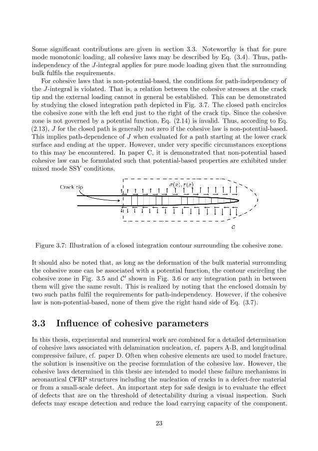
For cohesive laws that is non-potential-based, the conditions for path-independency ofthe J-integral is violated. That is, a relation between the cohesive stresses at the cracktip and the external loading cannot in general be established. This can be demonstratedby studying the closed integration path depicted in Fig. 3.7. The closed path encirclesthe cohesive zone with the left end just to the right of the crack tip. Since the cohesivezone is not governed by a potential function, Eq. (2.14) is invalid. Thus, according to Eq.(2.13), J for the closed path is generally not zero if the cohesive law is non-potential-based.This implies path-dependence of J when evaluated for a path starting at the lower cracksurface and ending at the upper. However, under very specific circumstances exceptionsto this may be encountered. In paper C, it is demonstrated that non-potential basedcohesive law can be formulated such that potential-based properties are exhibited undermixed mode SSY conditions.
Figure 3.7: Illustration of a closed integration contour surrounding the cohesive zone.
It should also be noted that, as long as the deformation of the bulk material surroundingthe cohesive zone can be associated with a potential function, the contour encircling thecohesive zone in Fig. 3.5 and C′ shown in Fig. 3.6 or any integration path in betweenthem will give the same result. This is realized by noting that the enclosed domain bytwo such paths fulfil the requirements for path-independency. However, if the cohesivelaw is non-potential-based, none of them give the right hand side of Eq. (3.7).
3.3 Influence of cohesive parameters
In this thesis, experimental and numerical work are combined for a detailed determinationof cohesive laws associated with delamination nucleation, cf. papers A-B, and longitudinalcompressive failure, cf. paper D. Often when cohesive elements are used to model fracture,the solution is insensitive on the precise formulation of the cohesive law. However, thecohesive laws determined in this thesis are intended to model these failure mechanisms inaeronautical CFRP structures including the nucleation of cracks in a defect-free materialor from a small-scale defect. An important step for safe design is to evaluate the effectof defects that are on the threshold of detectability during a visual inspection. Suchdefects may escape detection and reduce the load carrying capacity of the component.
23
In such cases, the FPZ cannot be considered to be of negligible size compared to otherrelevant dimensions. Under such conditions, a more detailed model of the fracture processis required and the predicted response may be affected by all details of the cohesive law.
As previously discussed, a large benefit of the CZM is its versatility to allow formodelling of crack growth in a wide variety of situations. Depending on the loadingconditions for which fracture is to be modelled, different parameters and features ofthe cohesive influence the results. In the extreme case of a cohesive zone subjected tohomogenous stress, the stress initiation criterion single-handedly dictates the fractureload. For mixed mode conditions, initiation is usually modelled using a criterion thattakes the interaction of the cohesive stresses into account. The most commonly usedinteraction criterion is the quadratic stress criterion proposed by Ye in [63] althoughseveral alternatives have been proposed, e.g. [61, 59]. In the opposite extreme situation,crack growth is modelled from a pre-existing crack and the fully developed cohesive zoneis of negligible size compared to other geometric dimensions. Under such circumstances,the cohesive fracture energy is the only parameter of importance. For pure mode I and IIloading, the fracture load is completely dictated by ΓI and ΓII, respectively in line withLEFM. However, care must be taken to this statement in the general mixed mode case.As discussed in the previous section, even when LEFM applies, the fracture load cannot ingeneral be related to the cohesive fracture energy given by the cohesive stress-separationhistory at the crack tip. This is only possible if the cohesive law is derived from a potentialfunction.
As the size of the fully developed cohesive zone increases relative to other relevantgeometric lengths, additional details of the cohesive formulation influence the predictions,cf. e.g. [64, 35, 29]. It is often suggested that the cohesive fracture energy and thecohesive strength, are the only parameters of importance. This holds in many situationsand has been demonstrated for e.g. ductile fracture by Hutchinson and Evans in [65]. Acomprehensive discussion on this topic is given in e.g. [64]. In their studies, the authorsconclude that additional details of the cohesive law may strongly influence the results.Latterly, further studies on the effect of individual cohesive parameters have been reportedin e.g. [66, 50, 64, 67, 68]. Many of these results suggest that all aspects of the cohesive lawshould be chosen with care and sometimes details that usually are considered unimportantsubstantially influence the macroscopic behaviour. A restriction is however necessary forthe case of mixed mode loading and the reported effects of cohesive parameters. It iscomplicated and sometimes impossible to relate variations of the results to one singlefeature of the cohesive law. For example, changing the shape of the cohesive law mayalso affect the cohesive fracture energy obtained. However, pure mode loading allows forstudies of the influence of individual features in isolation.
Usually, the effect of three features of the cohesive law formulation are examined, i.e.the cohesive strength, the cohesive fracture energy and the shape of the softening function.The latter is often considered unimportant and therefore chosen as simple as possible withthe bilinear softening model being the most commonly used. However, several studieshave been presented where the observations contradict this assumption, cf. [69, 70, 71,72, 64, 73, 74, 75]. This implies that the effect of the shape of the cohesive law may beunderestimated in numerical analysis of e.g. delamination nucleation.
In references [69, 70, 71], the authors investigate the response when the cohesive
24

fracture energy and cohesive strength is kept fixed while varying the shape of the softeningfunction. For example, in [69] it is demonstrated that both the critical load and thestability of the load displacement curve in simulations of the short beam shear test arestrongly affected. Moreover, in [70], the authors present simulations of three point bendingspecimens and curved specimens subjected to bending moments. Cohesive elements areinserted at all locations susceptible to delamination. The specimens contain discontinuousplies to simulate a ply drop. Both perfectly plastic and linear softening responses areused and successful prediction of the locations of delaminations is reported for bothformulations. Also, the failure loads are accurately predicted for the straight specimensfor both formulations. However, for the curves specimens, the failure load is successfullypredicted with the softening law while the perfectly plastic response gives un-conservativeresults. Furthermore, in [71], free edge delamination in laminates of various stackingsequences subjected to uniaxial tension are simulated. Different failure loads are obtained,although the effect is moderate, when using linear or exponential softening.
In [72], the authors calibrate the mode I cohesive law for fracture in various materialsusing notched and un-notched three-point bending specimens. For specimens with ashort initial crack and for un-cracked specimens, the mode I strength and the initialslope of the softening curves dictate the global response. That is, the peak load occursafter the cohesive strength is reached but before the cohesive zone is fully developed.With a suitable mode I strength and initial slope of the softening curve, the authorsalso accurately predict the load vs. notch opening displacement curves for beams withU-shaped notches made of concrete, PMMA and steel. In [64, 73], it is demonstrated thatfor more brittle decohesion, the shape of the traction-separation relation plays a decisiverole, sometimes even more important than the cohesive strength.
The shape of the cohesive law may be important when a dissipative material issurrounding the crack tip. In [64, 74], this is shown for a thin slice push-out test fora composite system. Interface failure between fibre and matrix is modelled using anelastic response for the fibre and an elasto-plastic response for the matrix. The simulatedresponse is completely different for various shapes of the mode II softening function.
These observations indicate that detailed formulation of the cohesive law may beimportant and it should be determined for each specific situation. Therefore, it isdesirable to determine cohesive laws based on experimental measurements. Experimentalmethods to extract cohesive laws from physical testing have been presented for adhesivejoints, in e.g. [76, 40, 77, 78, 79, 80, 62, 81] and for crack bridging in composites in e.g.[82, 45, 83, 84, 85]. In these works, the authors utilize the J-integral and its relationto the CZM as briefly discussed in the previous section. Recently, in [86], Jalalvand etal present an alternate technique to extract the mode II cohesive law associated withdelamination in CFRP. In-situ measurements of the mode II deformation of the resinrich interface is continuously measured and inserted into the in-plane shear constitutiverelation.
25
3.4 Element size requirements
One large benefit of using cohesive elements is the ability to provide relatively meshindependent results. The problem of highly mesh dependent results in the presence ofa stress singularity is often encountered when continuum damage models are used, e.g.[87]. The number of cohesive elements required for an accurate modelling of the fractureprocess is discussed in a number of articles, e.g. [88, 89]. A minimum of 2-3 elementswithin a fully developed cohesive zone is usually recommended. However, in [90] morethan 10 elements and in [91] more than 15 elements are recommended.
Various analytical models to estimate the fully developed cohesive zone lengths andthereby the required element size are commonly utilized. These models are discussed in[89]. Usually, they are based on the model proposed by Hillerborg in [38] that approximatesthe cohesive zone length for a semi-infinite crack in an infinite isotropic solid subjected toremote mode I loading,
ζ =EΓI
σ20
. (3.8)
Here, E is the plane stress or plane strain elastic modulus of the bulk. For orthotropicmaterials that are transversely isotropic, E denotes the transverse elastic modulus [89].
For delamination of CFRP, typical values of the mode I interlaminar strength andfracture energy gives rather small cohesive zones. The requirement of mesh refinementis therefore troublesome in larger scale structural simulations. Techniques to allow forcoarser meshes have been proposed, cf. [89]. Comparing ζ with other characteristicgeometrical lengths gives an indication whether or not the results are sensitive to thecohesive strength and additional details of the cohesive law [89, 50]. When ζ is small, thestrength can be reduced while keeping the cohesive fracture energy constant. Thus, largercohesive zones are obtained and thereby a coarser mesh may be used without affecting thestructural response. In [89], guidelines are given on the selection of appropriate cohesiveparameters. Of course, if the cohesive zone is enlarged too far, the structural responsemay be affected and become sensitive to individual cohesive parameters.
In papers A-C, more than 100 cohesive elements are placed within the fully developedcohesive zone. This is obviously an excessively high discretisation for most applications,e.g. to obtain converging fracture loads. However, the complete decohesion process isstudied and detailed modelling is required also in the initial stages of the simulations.
3.5 Initial stiffnesses
When cohesive elements of zero height are inserted in into a surrounding continuum withstiffness properties according to macroscopic bulk data, no cohesive opening should occurprior to the onset of damage. For this purpose, the authors in [47] implement an initiallyrigid cohesive model into a FE-software. This is carried out by automatically insertingcohesive elements into the element mesh once the stress reaches the initiation criterion.However, the use of cohesive elements in a traditional FE-code requires an initial finitestiffness. The separation that occurs prior to initiation of damage is limited by choosing
26
a very high elastic stiffness of the cohesive element. In [89], it is suggested that a lowerbound for the initial stiffness can be determined by K = αE3/t, where E3 is the throughthe thickness Young’s modulus and t is the thickness of the adjacent continuum. Theauthors suggest a minimum value of α ≥ 50 that results in a global stiffness loss less than2 %.
However, as demonstrated in [92], excessive initial stiffnesses may result in spuriousstress oscillations that precludes solution convergence. This is demonstrated in papersB-C in the simulation of mixed mode fracture. During linear elastic response, the modepartitioning at the crack tip should agree with LEFM, i.e. φI = GI and φII = GII.It is however noted that this is only achieved when initial stiffnesses below a certainlimit is used. This limit depends on the stiffness of the bulk and size of the continuumelements adjacent to the cohesive zone. The correlation between mesh sizing and allowableinitial stiffness is however weak and substantial mesh refinement is required to allow fora somewhat increased allowable stiffness. Moreover, for simulation of delamination inCFRP, it is noted that choosing the initial stiffnesses based on resin moduli and a typicalthickness of the resin-rich interface gives an order of magnitude higher initial stiffnessthan allowed.
3.6 Cohesive zones and LEFM
When the cohesive zone is small compared to other geometrical lengths the predictedresults should conform to the predictions given by LEFM. More specifically, it is desirablethat the model reproduces the experimental data obtained from fracture mechanicaltests. In [50] it is argued that, under such conditions, the mode partitioning shouldagree with the predictions of LEFM, i.e. φI = GI and φII = GII. With this capabilityat hand, calibration of the cohesive is straight forward and LEFM results are obtainedwhenever SSY conditions are present. However, in [59, 93, 66] it is demonstrated that thisis generally not the case in the simulation of delamination. Instead, the mode partitionhas shown to vary during non-linear response in the cohesive zone. These studies show apropensity towards normal separation is initiated at the onset of non-linear response inthe cohesive zone. Such behaviour makes calibration of the fracture criterion troublesomeif LEFM results are used for calibration of the cohesive law.
In [50], it is demonstrated that this behaviour is avoided by using an uncoupledcohesive law. The authors demonstrate that the mode partitioning coincide with LEFMfor a wide variety of softening functions provided that the cohesive zones are sufficientlysmall. For this model, a coupled fracture criterion is used that instantly drops the cohesivetraction to zero when a critical state of separation is reached.
3.7 Discussion of the results in paper C
In paper C, the conditions for which coupled cohesive laws are able to conform to LEFMare investigated. It is demonstrated that a constraint is required that relate the cohesivestiffnesses with the elastic stiffnesses of the orthotropic bulk. A second condition is foundnecessary that concern the formulation of the non-linear response of the cohesive law.
27
That is, a constant ratio between w and v must imply that φI and φII are constantlyrelated. This is not possible to achieve with a potential-based cohesive law that possess amode dependent Γ. It is shown that the initiation-driven and stress-based cohesive lawscan fulfill these two conditions and allow for a mode dependent mode mix.
As previously discussed, the use of a non-potential based cohesive laws implies thatthe J-integral is path dependent. Thus, the cohesive stresses at the crack tip cannotgenerally be directly related to the remotely applied J . It is however demonstrated thatthis difficulty can be by-passed during SSY conditions. With both conditions fulfilled,the stress-based cohesive law exhibits the properties of a potential.
4 Delamination
The lack of reinforcement in the through-the-thickness direction makes laminated compos-ites susceptible to delamination. Resin rich interfaces between plies accumulate damagethat leads to a complete separation of adjacent plies.
Delamination embedded within the laminate may be difficult to detect during inspection.It must therefore be considered that unnoticed delaminations may exist during serviceof the component. Moreover, it is widely known that the existence of delaminations,even small ones, may noticeably reduce the strength and stability of the component. Forexample, under compressive or flexural loading, delaminations have shown to promotemicro-buckling in the load-bearing plies leading to catastrophic failure of the laminate[94]. Moreover, delaminations tend to propagate under such loading conditions bybuckling of the sub-laminates, i.e. buckling driven delamination [95, 96]. The existenceof delaminations must therefore be accounted for already in the design of the structuralcomponent [95].
In [10], the critical role of delaminations is also demonstrated for the unnotched tensilestrength of multidirectional laminates. Laminates with different stacking sequences aretested, all with the same nominal stiffness and strength according to classical laminatetheory (CLT), cf. e.g. [97]. The results show a substantial variation of the laminatestrength and the strength predicted by CLT are unconservative for all lay-ups. This isexplained by the varying development of matrix cracks and free edge delaminations.
It is therefore important to enable prediction of the loading conditions for whichdelamination initiates and propagates. Experimental characterisation and modelling ofdelamination have been topics of intensive research during the four last decades. Theresearch progress has been summarized in useful review articles and books, e.g. [98] thatcovers the progress during the 1970’s and 1980’s, [96] that covers the years 1990-2001 withspecial emphasis on buckling driven delamination and more recently the comprehensivereview in [99] on experimental and numerical techniques.
4.1 Sources of delamination
In CLT, the laminate and the individual lamina are assumed to be under the condition ofplane stress, i.e. the stress components in the through-the-thickness direction are zero.
28

Although this is normally a valid assumption, there are circumstances where substantialinterlaminar stresses are present and may cause delamination. In Fig. 4.1, commonsources of interlaminar stresses are depicted. They correspond to locations of geometricor material discontinuities.
Figure 4.1: Sources of interlaminar stress. Picture: courtesy of professor Tonny Nyman,SAAB Aeronautics/Royal Institute of Technology, Sweden.
Geometric discontinuities are commonly encountered in various engineering applications.For example, internal ply drop-offs are used when a varying thickness of the laminateis desired. Axial loads are transferred to the continuous plies through interlaminarshear stresses. Also curved sections subjected to bending moments are locations wheredelaminations may occur due to the radial stresses. In the design of advanced compositestructures, both curved laminates and varying laminate thicknesses are necessary andmay be risk areas for delamination. Studies of delamination growth near ply drop-offs andcurved regions are investigated in e.g. [100] and [70]. Moreover, abrupt local discontinuitiesin the form of manufacturing defects, e.g. matrix cracks, cavities and damaged fibreswithin the laminate may be trigger points for delamination.
Material discontinuities are present at interfaces between plies of different orientationdue to the mismatch of mechanical properties. The adjacent plies have different normal-shear-coupling or Poisson’s ratios or possible both. When bonded, interlaminar shearstresses and sometimes tensile normal stresses are induced at free edges, at holes andnotches. Moreover, the varying fibre orientations results in a mismatch of coefficients ofthermal and moisture expansion. Thus, the working environment of the material needsto be considered in the design to avoid interlaminar damage growth. Also during curingwhere the laminate is heated and cooled may generate substantial interlaminar stresses,especially for multidirectional laminates that are curved.
29

Figure 4.2: Microscope image of an impacted laminate. Accompanied by fibre failuresand matrix cracking, multiple delaminations are present. Picture: courtesy of Dr. SorenNilsson, Swerea SiComp.
Out-of-plane loading is widely recognized as a critical source for delamination. Onescenario that is especially important in the aeronautical industry is that CFRPs areprone to delaminate due to impact loads that may occur by e.g. a strike of hail ora tool-drop. Figure 4.2 displays a microscope image of an impacted laminate wheremultiple delaminations are visible. Since delaminations are known to severely reduce thecompressive strength of the laminate, the research community has devoted much effort onthe characterisation of the compression after impact strength, e.g. [101].
As highlighted in [35], delamination usually interplays with other failure modes, inparticular intralaminar cracking. Because of the low transverse strength, intralaminarcracking can initiate at relatively low loads. These cracks give localized interlaminarstresses that cause delaminations [94]. Delaminations can interact through these matrixcracks and cause catastrophic failure of the laminate.
4.2 In-situ observations of delamination growth
The inelastic mechanisms that take place on the microscopic scale in the delaminationprocess are complicated. Due to the heterogeneity and anisotropic properties of thesematerials, the fracture processes are conceptually different than usually observed inhomogeneous isotropic materials. Important factors that influence the fracture process arefor example: the mode of loading, the properties of the matrix material and fibre/matrixadhesion. Moreover, the interfacial resin layer thickness and ply orientation of the adjacentplies have an impact on the microscopic process.
In homogeneous isotropic materials, fracture is often anticipated to take place as amode I crack, i.e. normal to the principal stress. However, the laminated structure, to alarge extent, restricts the nonlinear deformation to the resin layer in-between the adjacentplies that forms the delamination crack. This promotes delamination to nucleate under
30
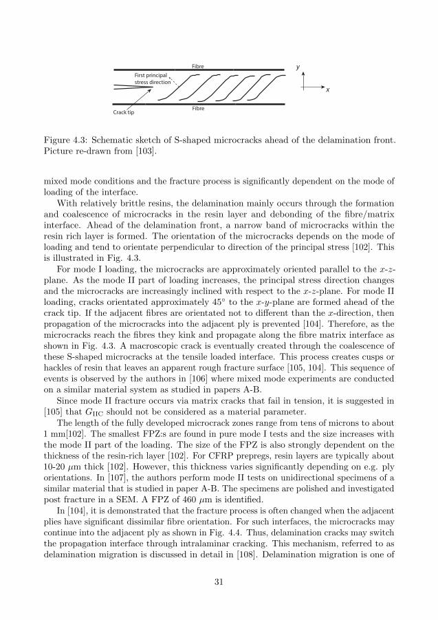
First principal stress direction
Crack tip
Fibre
Fibre
y
x
Figure 4.3: Schematic sketch of S-shaped microcracks ahead of the delamination front.Picture re-drawn from [103].
mixed mode conditions and the fracture process is significantly dependent on the mode ofloading of the interface.
With relatively brittle resins, the delamination mainly occurs through the formationand coalescence of microcracks in the resin layer and debonding of the fibre/matrixinterface. Ahead of the delamination front, a narrow band of microcracks within theresin rich layer is formed. The orientation of the microcracks depends on the mode ofloading and tend to orientate perpendicular to direction of the principal stress [102]. Thisis illustrated in Fig. 4.3.
For mode I loading, the microcracks are approximately oriented parallel to the x-z-plane. As the mode II part of loading increases, the principal stress direction changesand the microcracks are increasingly inclined with respect to the x-z-plane. For mode IIloading, cracks orientated approximately 45◦ to the x-y-plane are formed ahead of thecrack tip. If the adjacent fibres are orientated not to different than the x-direction, thenpropagation of the microcracks into the adjacent ply is prevented [104]. Therefore, as themicrocracks reach the fibres they kink and propagate along the fibre matrix interface asshown in Fig. 4.3. A macroscopic crack is eventually created through the coalescence ofthese S-shaped microcracks at the tensile loaded interface. This process creates cusps orhackles of resin that leaves an apparent rough fracture surface [105, 104]. This sequence ofevents is observed by the authors in [106] where mixed mode experiments are conductedon a similar material system as studied in papers A-B.
Since mode II fracture occurs via matrix cracks that fail in tension, it is suggested in[105] that GIIC should not be considered as a material parameter.
The length of the fully developed microcrack zones range from tens of microns to about1 mm[102]. The smallest FPZ:s are found in pure mode I tests and the size increases withthe mode II part of the loading. The size of the FPZ is also strongly dependent on thethickness of the resin-rich layer [102]. For CFRP prepregs, resin layers are typically about10-20 µm thick [102]. However, this thickness varies significantly depending on e.g. plyorientations. In [107], the authors perform mode II tests on unidirectional specimens of asimilar material that is studied in paper A-B. The specimens are polished and investigatedpost fracture in a SEM. A FPZ of 460 µm is identified.
In [104], it is demonstrated that the fracture process is often changed when the adjacentplies have significant dissimilar fibre orientation. For such interfaces, the microcracks maycontinue into the adjacent ply as shown in Fig. 4.4. Thus, delamination cracks may switchthe propagation interface through intralaminar cracking. This mechanism, referred to asdelamination migration is discussed in detail in [108]. Delamination migration is one of
31

σR ϕ
σR
σR ϕσR
Figure 4.4: Microcracking ahead of the crack tip. Left : 0◦-0◦ interface. Right : 0◦-90◦
interface. Picture slightly modified from [104].
the sources to the difficulties associated with delamination testing using multidirectionalspecimens, cf. section 4.3.
Although microcracking is considered as the major failure mechanism for relativelybrittle resins, plastic deformation is present as well. In [109], Bradley observes substantialresin strains in localized areas near the crack tip. For mode I, localized resin strainsexceeding 10 % are obtained for the relatively brittle composite system AS4/Dow P6. Thisis significantly higher than obtained by tensile tests of this resin. It is also demonstratedthat GIC for brittle composite systems are substantially larger than the neat resin mode Ifracture energies. This is mainly explained by the development of a longer FZP:s in thecomposite. For mode II tests on the brittle composite AS4/3501-6, a surprisingly highshear strain of 74 % is measured. It is however noted that the measured deformationmainly consists of microcracking and cusp formation rather than straining of the resin.Moreover, for brittle matrix materials, GIIC is considerable larger than GIC. The longerFPZ of microcracking found in mode II tests are considered the main reason for this.
Studies have been presented that suggest that the plastic zone ahead of the crack tipcannot be considered confined to the resin-rich layer. In [110], Olsson gives a comprehensivereview on factors that influence the GC in composites, e.g. the plastic yield zone ahead ofthe crack tip. As cited in [110], the plastic zone size in a brittle composite subjected to amode I test was measured by Parker in [111] where the yield zone found in the compositesystem was about eight times thicker than observed in tests of pure resin.
In [112], the authors conduct micromechanical FE-analyses of the delamination frontof a DCB-specimen. The material data used for the simulation describes a significantlymore brittle material than the material used in papers A-B. They found that the fibresinduced yield zones in the resin in-between the fibres in the adjacent plies. The authorstherefore suggest that the presence of fibres can actually increase the size of the yieldzone.
For tough matrix materials, the fracture process is conceptually different than observedfor brittle matrix materials [109]. The microcracking discussed above does not form andthe fracture process is similar for mode I and II loading. Fracture is governed byplastic deformation followed by ductile tearing for both modes and for very tough resinsGIC ' GIIC. It is also demonstrated that increasing GC of the composite by using a
32
tougher resin is only effective up till a certain limit. The laminated structure preventslarge yield zones to develop and thereby limits the effect of using a very tough resin.Moreover, as discussed in [110], the strength of the matrix/fibre interface may also limitGC of the composite material.
4.3 Characterisation of delamination resistance
Predictive tools for delamination are usually based on fracture mechanics and thereforerequire knowledge of GC. Determination of the interlaminar GC is normally based onLEFM unless toughening mechanisms that may yield large FPZ:s, such as fibre bridging,are assumed to be present. As discussed in section 4.2, for relatively brittle resins, thefracture process is highly dependent on the mode of loading. Consequently, experimentalexperience, e.g. [113], show that GC varies with the mode of loading. Thus, predictivetools require determination of GC for a range of modes and fracture is predicted as
GI +GII ≥ GC(Λglo). (4.1)
where the mode mix measure Λglo = GII/G is frequently used. Generally for CFRP:s, GC
takes its minimum value for pure mode I loading and increases as Λglo increases [104].In predictive models assuming LEFM, the experimentally obtained G-Λglo-relation
is approximated with a failure criterion. A commonly used criterion for delaminationrestricted to mode I/II combinations is the BK-criterion [113] given by
Gc = GIc + (GIIc −GIc)Ληglo (4.2)
where η is a curve fitting parameter. Multiple criteria have been proposed in the literature,cf. e.g. [114], where several criteria consider all three modes of loading.
Test methods for the determination of GC are reviewed in [115], [96] and more recentlyin [116]. The most adopted tests are the Double Cantilever Beam test (DCB) [117] formode I, the End Notch Flexure test (ENF) [118, 119] for mode II and the Mixed ModeBending test (MMB) [120] for mixed mode I/II loading. In the MMB-tests designed byReeder and Crews [121, 122], mixed mode I/II loading is applied to the specimen througha lever arm. Various mode mixities are conveniently obtained by adjustment of the leverarm length. These tests geometries are shown schematically in Fig 4.5.
Experimental tests are usually conducted on UD specimens even though delaminationin real composite components tend to occur between plies of different fibre orientation[104]. Thus, it has been questioned if the experimentally determined GC is representativefor the modelling of delamination [104]. The main reason that unidirectional specimensare used is the large difficulties to achieve true delamination in multidirectional specimens.When the fibre orientations are very different from the longitudinal direction of thespecimen, intralaminar matrix cracks tend to develop well before delamination takes place[123]. Moreover, delamination migration and multiple propagation planes contributeto an artificially increased GC during crack propagation [124, 125]. These mechanismsmake the conventional calculation methods for G invalid [123]. It has been demonstratedthat delamination tests on multidirectional specimens produce fracture surfaces that aresignificantly different than observed in real components [96, 104]. Moreover, GC is strongly
33

a)
b)
c)
Figure 4.5: a) Double cantilever beam (DCB). b) End notch flexure (ENF). c) Mixedmode bending (MMB).
dependent on the thickness of the resin-rich interface [104]. As discussed in section 4.2,thicker resin layers allows for larger FPZ:s to develop. Thus, the thinner resin layers foundin unidirectional specimens may give lower GC than multidirectional specimens. On theother hand, during crack extension, the thinner resin layers may promote substantiallyincreasing GC attributed to fibre bridging. In interfaces between aligned plies, fibres tendto nest. Thus, a bridging zone with cross-over fibres is often observed in the wake of thecrack during propagation in unidirectional specimens.
The effect of ply orientations on the initiation value of GC have been experimentallyexamined. It is often found that GC is almost unaffected by the ply orientations inmode I loading [126, 104]. For mixed mode and mode II loading, delamination betweenplies of different orientations results in GC that are generally higher than obtained withunidirectional laminates, e.g. [127, 128]. In [123], Andersons conducts a comprehensivetests series that includes MMB tests with 0.2 ≤ Λglo ≤ 0.8 on specimens with mismatchangles between plies from 0◦ to 90◦. It is found that GC generally increase with themismatch angle of adjacent plies. The effect is substantial for mode II dominated loadingbut decreases as the mode II part of loading decreases. Thus, it is generally conservative topredict onset of delamination based on GC obtained in tests on unidirectional specimens.
Related to the influence of the resin layer thickness is the discussion of the manufac-turing of the starter crack in delamination tests. Ideally, the initial crack front wouldconsist of a virgin resin-rich layer with the same thickness as found far ahead of the crackfront. However, manufacturing of such a starter crack is troublesome. Different methodsto produce the starter crack are discussed in the review given by Tay [96]. Usually, thestarter crack is formed by placing a Teflon film or an equivalent film between adjacentplies prior to curing of the laminate. It has been demonstrated that a resin pocket maybe formed near the tip that influences the measurement of GC [129]. Fracture of the resinpocket is required before a true delamination crack is formed. This gives an artificial high
34

value of GC and unstable crack propagation. The thickness of the resin pocket depends onthe thickness of the insert. Thus, the standards of the DCB- and MMB-tests recommendinserts not thicker than 13 µm [117, 120].
To circumvent these problems, specimens are commonly pre-cracked beyond the resinpocket. However, it is difficult to obtain a representative delamination front also withpre-cracking. Damage ahead of the crack tip is likely introduced and conservative GC istherefore promoted, especially in mode II dominated tests [130]. On the other hand, as aresult of mode I pre-cracking, bridging fibres behind the crack tip is likely to be presentthat would increase GC [131]. In [105], O’Brien discuss the significant difference of GIIC
obtained with specimens that are pre-cracked by mode II loading and specimens withinserts only. It is suggested that microcracks are formed ahead of the crack tip duringpre-cracking. In the tests, mode II delamination is created by the coalescence of thesepre-existing microcracks.
Delamination tests usually display increasing Gc during extension of the crack. Forunidirectional specimens, the source of increased resistance is mainly fibre bridging [132,133]. Substantial bridging zones may develop that makes the LEFM approach invalid, i.e.large scale bridging conditions are present. In [45], mixed mode cohesive laws associatedwith fibre bridging are measured using the J-integral approach.
4.4 Interlaminar strengths
The interlaminar strengths are substantially lower than the in-plane strength of multidi-rectional laminates and thereby limiting parameters for safe design of CFRP components.With LEFM based methods, there is no concept of strengths and crack growth is governedby the energy release rates alone. However, to enable prediction of delamination whenLEFM is inappropriate, accurate values of the interlaminar strengths are crucial. Boththe CZM and damage mechanics based models require the interlaminar strength as inputparameters. In the extreme case of homogenous interlaminar stress, the interlaminarstrengths single-handily dictates when delamination occurs.
The interlaminar shear and tensile strength are properties that are very difficult tocharacterise. Therefore, it is common to approximate the interlaminar strengths with thetransverse in-plane strengths. There is yet no widely accepted method to measure thein-situ interlaminar strengths that acts on the resin layer between plies.
There are standardized tests for the measurement of the ”apparent” interlaminar tensileand shear strength. The term apparent is commonly used due to the fact that these testsproduce rather complex stress states. However, the tests are considered to give dominatinginterlaminar tensile and shear stress, respectively. Thus, the results are considered validfor comparison and as a quality assurance [135, 136].
For measurement of the tensile strength, a curved beam subjected to four-pointbending is frequently utilized [135]. The specimens are unidirectional laminates with a90◦ out-of-plane bend located at half the span length, cf. Fig. 4.6. The bending momentgives rise to localized interlaminar tensile stress in the curved region. A major drawbackwith this test is the difficulty to manufacture a curved region of good quality. The localregion near the curvature often displays increased porosity and reduced fibre content and
35
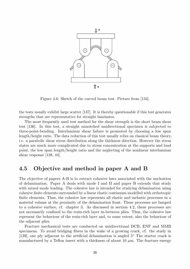
Figure 4.6: Sketch of the curved beam test. Picture from [134].
the tests usually exhibit large scatter [137]. It is thereby questionable if this test generatesstrengths that are representative for straight laminates.
The most frequently used test method for the shear strength is the short beam sheartest [136]. In this test, a straight unnotched unidirectional specimen is subjected tothree-point-bending. Interlaminar shear failure is promoted by choosing a low spanlength/height ratio. The data reduction of this test usually relies on classical beam theory,i.e. a parabolic shear stress distribution along the thickness direction. However the stressstates are much more complicated due to stress concentration at the supports and loadpoint, the low span length/height ratio and the neglecting of the nonlinear interlaminarshear response [138, 44].
4.5 Objective and method in paper A and B
The objective of papers A-B is to extract cohesive laws associated with the nucleationof delamination. Paper A deals with mode I and II and paper B extends that studywith mixed mode loading. The cohesive law is intended for studying delamination usingcohesive finite elements surrounded by a linear elastic continuum modelled with orthotropicfinite elements. Thus, the cohesive law represents all elastic and inelastic processes in amaterial volume at the proximity of the delamination front. These processes are lumpedto a cohesive surface, cf. chapter 3. As discussed in section 4.2, these processes arenot necessarily confined to the resin-rich layer in-between plies. Thus, the cohesive lawrepresent the behaviour of the resin-rich layer and, to some extent, also the behaviour ofthe adjacent plies.
Fracture mechanical tests are conducted on unidirectional DCB, ENF and MMBspecimens. To avoid bridging fibres in the wake of a growing crack, cf. the study in[139], one ply adjacent to the artificial delamination is angled 5◦ The starter crack ismanufactured by a Teflon insert with a thickness of about 10 µm. The fracture energy
36
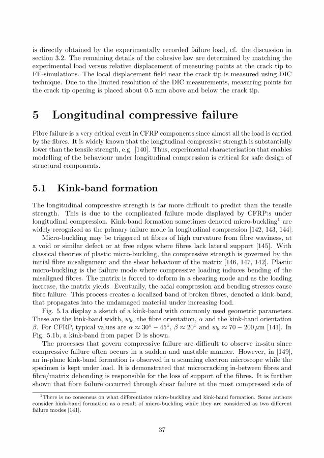
is directly obtained by the experimentally recorded failure load, cf. the discussion insection 3.2. The remaining details of the cohesive law are determined by matching theexperimental load versus relative displacement of measuring points at the crack tip toFE-simulations. The local displacement field near the crack tip is measured using DICtechnique. Due to the limited resolution of the DIC measurements, measuring points forthe crack tip opening is placed about 0.5 mm above and below the crack tip.
5 Longitudinal compressive failure
Fibre failure is a very critical event in CFRP components since almost all the load is carriedby the fibres. It is widely known that the longitudinal compressive strength is substantiallylower than the tensile strength, e.g. [140]. Thus, experimental characterisation that enablesmodelling of the behaviour under longitudinal compression is critical for safe design ofstructural components.
5.1 Kink-band formation
The longitudinal compressive strength is far more difficult to predict than the tensilestrength. This is due to the complicated failure mode displayed by CFRP:s underlongitudinal compression. Kink-band formation sometimes denoted micro-buckling1 arewidely recognized as the primary failure mode in longitudinal compression [142, 143, 144].
Micro-buckling may be triggered at fibres of high curvature from fibre waviness, ata void or similar defect or at free edges where fibres lack lateral support [145]. Withclassical theories of plastic micro-buckling, the compressive strength is governed by theinitial fibre misalignment and the shear behaviour of the matrix [146, 147, 142]. Plasticmicro-buckling is the failure mode where compressive loading induces bending of themisaligned fibres. The matrix is forced to deform in a shearing mode and as the loadingincrease, the matrix yields. Eventually, the axial compression and bending stresses causefibre failure. This process creates a localized band of broken fibres, denoted a kink-band,that propagates into the undamaged material under increasing load.
Fig. 5.1a display a sketch of a kink-band with commonly used geometric parameters.These are the kink-band width, wk, the fibre orientation, α and the kink-band orientationβ. For CFRP, typical values are α ≈ 30◦ − 45◦, β ≈ 20◦ and wk ≈ 70− 200µm [141]. InFig. 5.1b, a kink-band from paper D is shown.
The processes that govern compressive failure are difficult to observe in-situ sincecompressive failure often occurs in a sudden and unstable manner. However, in [149],an in-plane kink-band formation is observed in a scanning electron microscope while thespecimen is kept under load. It is demonstrated that microcracking in-between fibres andfibre/matrix debonding is responsible for the loss of support of the fibres. It is furthershown that fibre failure occurred through shear failure at the most compressed side of
1There is no consensus on what differentiates micro-buckling and kink-band formation. Some authorsconsider kink-band formation as a result of micro-buckling while they are considered as two differentfailure modes [141].
37
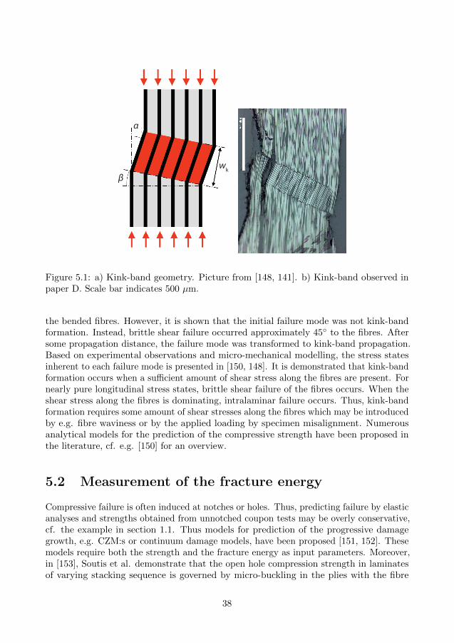
wk
α
β
Figure 5.1: a) Kink-band geometry. Picture from [148, 141]. b) Kink-band observed inpaper D. Scale bar indicates 500 µm.
the bended fibres. However, it is shown that the initial failure mode was not kink-bandformation. Instead, brittle shear failure occurred approximately 45◦ to the fibres. Aftersome propagation distance, the failure mode was transformed to kink-band propagation.Based on experimental observations and micro-mechanical modelling, the stress statesinherent to each failure mode is presented in [150, 148]. It is demonstrated that kink-bandformation occurs when a sufficient amount of shear stress along the fibres are present. Fornearly pure longitudinal stress states, brittle shear failure of the fibres occurs. When theshear stress along the fibres is dominating, intralaminar failure occurs. Thus, kink-bandformation requires some amount of shear stresses along the fibres which may be introducedby e.g. fibre waviness or by the applied loading by specimen misalignment. Numerousanalytical models for the prediction of the compressive strength have been proposed inthe literature, cf. e.g. [150] for an overview.
5.2 Measurement of the fracture energy
Compressive failure is often induced at notches or holes. Thus, predicting failure by elasticanalyses and strengths obtained from unnotched coupon tests may be overly conservative,cf. the example in section 1.1. Thus models for prediction of the progressive damagegrowth, e.g. CZM:s or continuum damage models, have been proposed [151, 152]. Thesemodels require both the strength and the fracture energy as input parameters. Moreover,in [153], Soutis et al. demonstrate that the open hole compression strength in laminatesof varying stacking sequence is governed by micro-buckling in the plies with the fibre
38

orientation aligned with the loading direction. Therefore, it is desirable to determine thefracture energy associated with longitudinal compression.
Since the early 1990’s, several methods have been presented for the experimentaldetermination of the fracture energy associated with longitudinal compression, cf. [144]for a discussion. Pinho et al. [144] use a Compact Compression specimen with a cross-plylaminate. The fracture energy is calculated at the maximum load. By conducting a linearelastic finite element simulation and J-integral calculations, the relation between theapplied load and the energy release rate is determined. Later in [154], four-point-bendingtests are conducted using notched unidirectional specimens. Similar to [144], a relationis calculated between the energy release rate and the applied load by using linear finiteelement analysis. It is observed that failure occurred by brittle shear failure. Thesemethods all rely on that the FPZ is of negligible size. However, this assumption is avoidedin [155]. In [155], the authors conduct experiments with the compact compression crossply specimen suggested by Pinho [144]. The energy release rate is measured by evaluatingthe J-integral from the actual strain field using Digital Image Correlation (DIC). Theintegration path encircles the complete notch. Recently, a framework for measurement ofthe complete resistance curve associated with kink-band propagation is proposed in [156].
With the exception of [154], all references above consider compressive failure in cross-ply laminates. Thus, partitioning of the fracture energy is needed and interaction effectsbetween off-axis plies are neglected [154]. This suggests that measurement of the fractureenergy should be conducted with UD-laminates. However, a possible draw-back withusing UD-laminates is that kinking tends to mainly occur in the out-of-plane direction.For multidirectional laminates, as always used in real structural components, kinkingusually develops in-plane. However, in [145] it is pointed out that cross-plies also promoteout-of-plane kinking. Moreover, it is shown that, for varying lay-ups of (±θ/02)2S, in-planekinking is observed for θ = 30◦, θ = 45◦ and θ = 60◦.
5.3 Objective and method in paper D
In paper D, the objective is to experimentally extract the cohesive law associated with kink-band formation in a UD-laminate. With the present specimen, the out-of-plane thicknessis continuously reduced towards the zone that fails in compression. This geometry is usedin order to achieve longitudinal compressive failure in a UD laminate. A microscopicstudy shows a kink-band with a large out-of-plane component in the UD-region, cf. Fig.5.1b. The cohesive law represents the material volume with a height of 200 µm similarto the kink-band height displayed in Fig. 5.1b. The proposed data reduction scheme isbased on the concept of configurational forces [157] and DIC measurement of the strainfield. For this kind of geometry, this concept is strongly related to the J-integral concept,cf. section 2.2. Thus, no assumption of a small FPZ is made. The extracted cohesivelaws suggest strengths similar to usually reported for prepregs while the fracture energyis well below those reported in the references in section 5.2. The relatively high strengthsmeasured are considered reasonable for this test geometry. The material volume subjectedto substantial compressive stress in the presented experiments is considerably smaller thanin conventional unnotched bulk tests. That is, the risk that defects are present within the
39
tested volume is lower in the present tests than in conventional unnotched tests. Sincemeasurement of the compressive strength is very sensitive to initial material defects, thisimplies that higher strength measures are promoted with the presented geometry. Suchsize effect is reported for specimens failing by kink-band formation in [158].
6 Summary of appended papers
Paper A
A method to extract the cohesive laws associated with mode I and II delamination in aCFRP laminate is presented. The evaluation method is based on data from DCB and ENFtests and involves measurements of the displacement field near the crack tip using digitalimage correlation. Finite element simulations and an optimization procedure are utilizedto extract the cohesive laws. For loading in mode I, the fracture energy and cohesivestrength are in the order of 300 J/m2 and 75 MPa, respectively. The corresponding valuesfor mode II loading are 1200 J/m2 and 80 MPa. In mode I, the cohesive law displays asoftening response shortly after the strength is reached while a substantial part of constantshear stress is obtained prior to softening for mode II.
Paper B
An experimental method to extract cohesive laws associated with mixed mode delaminationis developed. The method is based on MMB tests and measurements of the displacementfield near the crack tip. An initiation driven mixed mode cohesive law is proposed, forwhich the behaviour in the cohesive zone is given by the conditions at the crack tip. Thisfacilitates a straightforward evaluation of the cohesive parameters from experimentallyobtained fracture energies and critical separations near the crack tip. Verifying finiteelement simulations show that the experimentally determined cohesive law reproducesthe load versus the local displacement near the crack tip with good accuracy.
Paper C
The influence of initial cohesive stiffnesses and the formulation of the nonlinear behaviourof mixed mode cohesive laws are under discussion. More specifically, properties of cohesivelaws are specified that enable degeneration to LEFM results under mixed mode smallscale yielding conditions. By analytical derivations, two conditions are concluded sufficientto achieve this. The first condition is a constraint that relates the initial stiffnessesto the elastic stiffnesses of the orthotropic material. The second condition states thatthe mode mix in terms of the mode I and II energy cannot vary when the associatedseparations are constantly related. It is shown that the second condition cannot befulfilled with a potential-based cohesive law that possesses a mode dependent cohesivefracture energy. These conclusions are validated with FE-analyses of an orthotropic
40

planar body subjected to loading assuming SSY conditions. It is demonstrated that,provided that both conditions are met, the mode I and II energy release rates agreewith the counterparts given by the prescribed edge displacements. Furthermore, twocohesive laws referred to as stress-based and initiation-driven laws can be designed tofulfil the conditions and allow for a mode dependent fracture energy. Simulations arealso conducted on the MMB-geometry to investigate the effect of a finite geometry. It isshown that the conditions minimize the discrepancy to LEFM predictions.
Paper D
A method to extract the cohesive law associated with longitudinal compressive failureis presented. Equilibrium of configurational forces is used to design and evaluate theexperiments. Microscopic studies show that a kink-band with the height of about 200 µmis formed in the UD-laminate. The corresponding cohesive laws shows a peak stress ofabout 1.5 GPa, a compression at failure of about 50 µm and a fracture energy of about25 kJ/m2.
7 Future work
During this work, several possibilities for future developments have been identified.Paper A and B focus on the extraction of cohesive laws associated with delamination.
The determination of cohesive parameters relies on measurement of the displacementfield of the crack tip region. For this purpose, DIC-measurements are utilized and thedisplacements of two points located about 1 mm apart are used in the evaluation. It isreasonable to assume that the inelastic behaviour present at the proximity of the cracktip is embedded in a region substantially smaller than that. Thus, measurement on alower scale is desirable. An ambitious goal would be to experimentally measure the heightof the FPZ and position the measuring points based on that knowledge.
In paper C, the design rules for the formulation of cohesive laws are presented. Withthese rules satisfied, CZM:s degenerate to the LEFM predictions under SSY conditions.This allows for a number of interesting continuations. For example, an extension ofthe design rules to handle bi-material interface and mode III loading to allow for 3Dsimulations of delamination between plies of different orientations.
In paper D, a method is presented for the measurement of cohesive laws associatedwith kink-band formation in a UD-laminate. Earlier attempts to experimentally determinecohesive laws have not been identified. The presented work shows promising potential butinvolves a rather elaborate data reduction scheme. A simplification of the test set-up thatallows for a larger number of tests is desirable. Such a method is under development.
41
References
[1] R. Koide, G. von Zeska de Franca, and M. Luersen. An ant colony algorithmapplied to lay-up optimization of laminated composite plates. Latin AmericanJournal of Solids and Structures 10(3) (2013), (On–line version ISSN 1679–7825).
[2] Boeing 787 from the ground up. QTR 04 06.[3] url = ”http://modernairliners.com/Boeing787files/Specifications.html”.[4] H. Fenbert. “Composites in commercial aircraft a production cost perspective”.
ICCM/9: Composites properties and applications. 1993.[5] Composite Materials Handbook, MIL-HDBK-17-3F, U.S. Department of Defence,2002.[6] A. Mouritz. Introduction to Aerospace Materials. Woodhead Publishing Ltd, Cam-
bridge, 2012, (ISBN 9871855739468), pp.621., 2012.[7] T. Nyman. “Fatigue and residual strength of composite aircraft structures”. PhD
thesis. KTH, Aeronautical Engineering, 1999.[8] Private communication with Tonny Nyman at SAAB Aerostructures Linkoping.[9] P. Treasurer. “Characterization and analysis of damage progression in non-traditional
composite laminates with circular holes”. MA thesis. Georgia Institute of Technol-ogy, 2006.
[10] M. Wisnom, B. Khan, and S. Hallett. Size effects in unnotched tensile strength ofunidirectional and quasi-isotropic carbon/epoxy composites. Composite Structures84 (2008), 21–28.
[11] M. Wisnom, S. Hallet, and C. Soutis. Scaling effects in notched composites. Journalof Compiste Materials 44 (2010), 195–210.
[12] J. Lee and C. Soutis. Measuring the notched compressive strength of compositelaminates: Specimen size effects. Composite Science and Technology 68 (2008),2359–2366.
[13] F. Edgren. “Physically based engineering models for NCF composites”. PhD thesis.Royal Institute of Technology, Sweden, 2006.
[14] F. Edgren, L. Asp, and R. Joffe. Failure of NCF composites subjected to combinedcompression and shear loading. Composite Science and Technology 66(15) (2006),2865–77.
[15] M. Laffan et al. Translaminar fracture toughness testing of composites: A review.Polymer Testing 31 (2012), 481–489.
[16] C. Inglis. Stresses in a plate due to the presence of cracks and sharp corners. Trans.Inst. Nav. Archit. London 55 (1913), 219–230.
[17] A. Griffith. The phenomena of rupture and flow in solids. Phil. Trans. R. Soc. A221 (1921), 163–98.
[18] G. Irwin. Onset of fast crack propagation in high strength steel and aluminumalloys. Sagamore Research Conference proceedings 2 (1956), 289–305.
[19] H. Tada, P. Paris, and G. Irwin. Stress analysis of cracks handbook. Del Reasearch,St. Louis, MO, 1985.
[20] Z. Sou et al. Orthotropy rescaling and implications for fracture in composites.International Journal of Solids and Structures 28(2) (1991), 235–248.
42
[21] G. Bao et al. The role of material orthotropy in fracture specimens for composites.International Journal of Solids and Structures 29 (1991), 1105–1116.
[22] url = ”http://en.wikipedia.org/wiki/Stressintensityfactor”.[23] G. Sih, P. Paris, and G. Irwin. On cracks in rectilinearly anisotropic bodies.
International Journal of Fracture Mechanics 1 (1965), 189–203.[24] Linear elastic fracture mechanics 2014 03 08. url = ”http://imechanica.org/files/Linear
elastic fracture mechanics 2014 03 08.pdf”.[25] S. Lekhnitskii. Theory of elasticity of an anisotropic body. Mir publisher, Moscow,
1981.[26] K. Alfredsson and U. Stigh. Stability of beam-like fracture mechanics specimens.
Engineering Fracture Mechanics 89 (2012), 98–113.[27] M. Juntti, L. Asp, and R. Olsson. Assessment of Evaluation Methods for the
Mixed-Mode Bending Test. Journal of Composites Technology and Research 21(1999), 37–48.
[28] J. Rice. A path independent integral and the approximative analysis of strainconcentration by notches and holes. Journal of Applied Mechanics 88 (1968),379–386.
[29] A. Needleman. “Some issues in cohesive surface modelling”. 23rd InternationalCongress of Theoretical and Applied Mechanics. 2014.
[30] J. Rice. “The mechanics of quasi-static crack growth”. Proceedings of the eighthU.S. National congress of applied mechanics. 1979.
[31] F. Nilsson. Fracture Mechanics - from Theory to applications. Fingraf, Sodertalje,Sweden, 2001.
[32] B. Budiansky. A reassessment of deformation theories of plasticity. Journal ofApplied Mechanics 26 (1959), 259–264.
[33] V. Tvergaard and J. Hutchinson. The relation between crack growth restistanceand fracture process parameters in elastic-plastic solids. Journal of the Mechanicsand Physics of Solids 40 (1992), 1377–97.
[34] T. L. Anderson. Fracture Mechanics: Fundamentals and Applications, Third Edition.Boca Raton, FL: Taylor & Francis/CRC Press, 2005.
[35] M. R. Wisnom. Modelling discrete failure in composites with interface elements.Composites Part A 41 (2010), 795–805.
[36] G. Barenblatt. The mathematical theory of equilibrium cracks in brittle fracture.Advances in Applied Mechanics 7 (1962), 55–129.
[37] D. Dugdale. Yielding of steel sheets containing slits. Journal of the Mechanics andPhysics of Solids 8 (1960), 100–104.
[38] A. Hillerborg, M. Modeer, and P. Peterson. Analysis of crack formation and crackgrowth in concrete by means of fracture mechanics and finite elements. Cementand Concrete Research 6 (1976), 773–782.
[39] A. Needleman. A continuum model for void nucleation by inclusion debonding.Journal of Applied Mechanics 54 (1987), 525–532.
[40] Q. Yang and M. Thouless. Mixed mode fracture of plastically-deforming adhesivejoints. International Journal of Fracture 110 (2001), 175–187.
[41] X. Xu and A. Needleman. Void nucleation by inclusion debonding in crystal matrix.Model Simul Mater Sci 1 (1993), 111–132.
43
[42] O. Allix and P. Ladeveze. Interlaminar interface modeling for the prediction ofdelamination. Composite Structures 22(4) (1992), 235–242.
[43] J. Schellekens and R. De Borst. A non-linear finite element approach for theanalysis of mode I free edge delamination in composites. International Journal ofSolids and Structures 30(9) (1993), 1239–1253.
[44] W. Cui and M. R. Wisnom. A combined stress-based and fracture-mechanics-basedmodel for predicting delamination in composites. Composites 24 (1993), 467–74.
[45] B. Sørensen and P. Kirkegaard. Determination of mixed mode cohesive laws.Engineering Fracture Mechanics 73 (2006), 2642–2661.
[46] V. Tvergaard. Effect of fibre debonding in a whisker-reinforced metal. MaterialScience and Engineering A 125 (1990), 203–13.
[47] G. Camacho and M. Ortiz. Computational modelling of impact damage in brittlematerials. International Journal of Solids and Structures 33 (1996), 2899–938.
[48] M. van der Bosch, P. Schreurs, and M. Geers. An improved description of theexponential Xu and Needleman cohesive zone law for mixed-mode decohesion.Engineering Fracture Mechanics 73 (2006), 1220–1234.
[49] S. Goutianos and B. Sorensen. Path dependence of truss-like mixed mode cohesivelaws. Engineering Fracture Mechanics 91 (2012), 117–132.
[50] R. Sills and M. Thouless. The effect of cohesive-law parameters on mixed-modefracture. Engineering Fracture Mechanics 109 (2013), 353–368.
[51] V. Tvergaard and J. Hutchinson. The Influence of plasticity on mixed modeinterface toughness. Journal of the Mechanics and Physics of Solids 41(6) (1993),1119–35.
[52] X. Xu and A. Needleman. Numerical simulations of fast crack growth in brittlesolids. Journal of the Mechanics and Physics of Solids 42(9) (1994), 1397–434.
[53] B. Sørensen et al. Micromechanical model of cross-over fibre bridging prediction ofmixed mode bridging laws. Mechanics of materials 40 (2008), 220–34.
[54] K. Park, G. Paulino, and J. Roesler. A unified potential-based cohesive model ofmixed mode fracture. Journal of the Mechanics and Physics of Solids 57 (2009),891–908.
[55] J. McGarry et al. Potential-based and non-potential-based cohesive zone formula-tions under mixed-mode separation and over-closure. Part I: Theoretical analysis.Journal of the Mechanics and Physics of Solids 63 (2014), 336–362.
[56] E. Mairtin et al. Potential-based and non Potential-based cohesive zone formulationsunder mixed-mode separation and over-closure - Part II: Finite element applications.Journal of the Mechanics and Physics of Solids 63 (2014), 363–385.
[57] P. Camanho, C. Davila, and M. de Moura. Numerical simulation of mixed-modeprogressive delamination in composite materials. Journal of Compiste Materials37(16) (2003), 1415–38.
[58] A. Turon et al. A damage model for the simulation of delamination in advancedcomposites under variable-mode loading. Mechanics of materials 38 (2006), 1079–1089.
[59] A. Turon et al. Accurate simulation of delamination growth under mixed-modeloading using cohesive elements: Definition of interlaminar strength and elasticstiffness. Composite Structures 92 (2010), 1857–1864.
44
[60] J. Hogberg. Mixed mode cohesive law. International Journal of Fracture 141(2006), 549–559.
[61] N. Jansson and R. Larsson. A damage model for simulation of mixed-mode delam-ination growth. Composite Structures 53 (2001), 409–417.
[62] J. Hogberg, B. Sorensen, and U. Stigh. Constitutive behaviour of mixed modeloaded adhesive layer. International Journal of Solids and Structures 44 (2007),8335–54.
[63] L. Ye. Role of Matrix Resin in Delamination onset and growth in compositelaminates. Composite Science and Technology 33 (1988), 257–277.
[64] N. Chandra et al. Some issues in the application of cohesive zone models formetal-ceramic interfaces. International Journal of Solids and Structures 39 (2002),2827–2855.
[65] J. Hutchinson and A. Evans. Mechanics of materials: top-down approach to fracture.Acta Metallurgica 48 (2000), 125–35.
[66] P. Harper, L. Sun, and S. Hallet. A study on the influence of cohesive zone interfaceelement strength parameters on mixed mode behaviour. Composites Part A 43(2012), 722–734.
[67] P. Gustafson and A. Waas. The influence of adhesive constitutive parameters incohesive zone finite element models of adhesively bonded joints. InternationalJournal of Solids and Structures 46 (2009), 2201–2215.
[68] G. Alfano. On the influence of shape of the interface law on the application ofcohesive-zone models. Composite Science and Technology 66 (2006), 723–730.
[69] M. R. Wisnom. Modelling of stable and unstable fracure of short beam shearspecimens. Composites 25 (1994), 394–400.
[70] Z. Petrossian and M. R. Wisnom. Prediction of delamination initiation and growthfrom discontinuous plies using interface elements. Composites Part A: AppliedScience and Manufacturing 29.56 (1998), 503 –515.
[71] A. Uguen et al. “Comparison of cohesive zone models used to predict delaminationinitiated from free-edges: validation against experimental results”. ECCM-16THEuropean Conference on Composite Materials. 2014.
[72] M. Elices et al. The cohesive zone model: advantages, limitations and challanges.Engineering Fracture Mechanics 69 (2002), 137–163.
[73] J. Rots. Strain-softening analysis of concrete fracture specimens. Ed. by e. WittmannFH. In: Wittmann FH, editor. Fracture toughness and fracture energy of concrete.Amsterdam, The Netherlands: Elsevier Science Publishers, 1986, p. 137-48.
[74] C. Shet and N. Chandra. Effect of the Shape of t− δ Cohesive Zone Curves on theFracture Response. Mechanics of Advanced Materials and Structures 11 (2004),249–275.
[75] M. Jalalvand, G. Czel, and M. Wisnom. “Numerical modelling of the damagemodes in UD thin carbon/glass hybrid laminates - sensitivity analysis”. Camanho,P.P. and Soleman, A., editors. Compos. 2013 Conf., Ponta Del Gada. p. 1-15.2013.
[76] U. Stigh and T. Andersson. “An experimental method to determine the completestress-elongation relation for a structural adhesive layer loaded in peel”. Proceed-ings of the 2nd ESIS TC4 Conference on Polymers and Composites. Amsterdam:
45
Elsevier; p. 297-306 [ESIS Publication 27], Eds. J.G. Williams and A. Pavan.2000.
[77] B. Sørensen. Cohesive law and notch sensitivety of adhesive joints. Acta Mater 50(2002), 1053–61.
[78] T. Andersson and U. Stigh. The stress-elongation relation for an adhesive layerloaded in peel using equilibrium of energetic forces. International Journal of Solidsand Structures 41 (2004), 413–34.
[79] S. Li et al. Mixed-mode cohesive-zone models for fracture of an adhesively bondedpolymer-matrix composite. Engineering Fracture Mechanics 73(1) (2006), 64–78.
[80] K. Leffler, K. Alfredsson, and U. Stigh. Shear behaviour of adhesive layers. Inter-national Journal of Solids and Structures 44 (2007), 530–45.
[81] Y. Zhu, K. Liechti, and K. Ravi-Chandar. Direct extraction of rate-dependenttractionseparation laws for polyurea/steel interfaces. International Journal ofSolids and Structures 46 (2009), 31–51.
[82] B. Sørensen and T. Jacobsen. Large-scale bridging in composites: R-curves andbridging laws. Composites Part A: Applied Science and Manufacturing 29.11(1998), 1443–1451.
[83] L. Sorensen et al. Bridging tractions in mode I delamination; measurement andsimulations. Composite Science and Technology 68 (2008), 2350–8.
[84] B. Sørensen and T. K. Jacobsen. Characterizing delamination of fibre composites bymixed mode cohesive laws. Composite Science and Technology 69 (2009), 445–56.
[85] C. Sun and Z. Jin. Modeling of composite fracture using cohesive zone and bridgingmodels. Composite Science and Technology 66 (2006), 1297–302.
[86] M. Jalalvand, G. Czel, and M. R. Wisnom. “Extracting cohesive laws from dis-placement field measurement”. 29th Annual Technical Conference of the AmericanSociety for Composites 2014. 2014.
[87] G. Ljustina, M. Fagerstrom, and R. Larsson. Rate Sensitive Continuum DamageModels and Mesh Dependence in Finite Element Analyses. The Scientific WorldJournal 2014:260571 (2014), DOI: 10.1155/2014/260571.
[88] P. Harper and S. Hallet. Cohesive zone length in numerical simulations of compositedelamination. Engineering Fracture Mechanics 75 (2008), 4774–92.
[89] A. Turon et al. An engineering solution for mesh size effects in the simulationof delamination using cohesive zone models. Engineering Fracture Mechanics 74(2007), 1665–1682.
[90] V. Tomar, J. Zhai, and M. Zhou. Bounds for element size in a variable stiffnesscohesive finite element model. International Journal of Numerical Methods 61(11)(2004), 1894–1920.
[91] C. Fan, P. Jar, and J. Cheng. Cohesive zone with continuum damage properties forsimulation of delamination development in fibre composites and failure of adhesivejoints. Engineering Fracture Mechanics 75(13) (2008), 3866–3880.
[92] J. Schellekens and R. de Borst. On the numerical integration of interface elements.International Journal for Numerical Methods in Engineering 36 (1992), 43–66.
[93] C. Sarrado et al. Assessment of energy dissipation during mixed-mode delaminationgrowth using cohesive zone models. Composites Part A 43 (2012), 2128–2136.
46

[94] E. S. Greenhalgh and M. Hiley. The assessment of novel materials and processes forthe impact tolerant design of stiffened composite aerospace structures. CompositesPart A: Applied Science and Manufacturing 34 (2003), 151–161.
[95] L. Asp, S. Nilsson, and S. Singh. An experimental Investigation of the influence ofdelamination growth on the residual strength of impacted laminates. CompositesPart A 32 (2001), 1229–35.
[96] T. Tay. Characterization and analysis of delamination fracture in composites: Anoverview of developments from 1990 to 2001. Appl Mech Rev 56 (2003), no 1.
[97] I. Daniel and O. Ishai. Engineering mechanics of composite materials. Ed. by I.Daniel. Oxford university press, 2006.
[98] A. Garg. Delamination - a damage mode in composite structures. EngineeringFracture Mechanics 29 (1988), 557–584.
[99] S. Sridharan. Delamination behaviour of composites. Ed. by S. Sridharan. InWoodhead Publishing Series in Composites Science and Engineering, 2008.
[100] A. Weiss et al. Influence of ply-drop location on the fatigue behaviour of taperedcomposites laminates. Procedia Engineering 2.1 (2010), 1105 –1114.
[101] C. Soutis and P. Curtis. Prediction of post-impact compressive strength of CFRPlaminated composites. Composite Science and Technology 56 (1996), 677–684.
[102] Q. Yang and B. Cox. Cohesive models for damage evolution in laminated composites.International Journal of Fracture 133 (2005), 107–137.
[103] M. Hibbs and W. Bradley. Correlations Between Micromechanical Failure Processesand the Delamination Toughness of Graphite/Epoxy Systems. Fractography ofModern Engineering Materials: Composites and Metals, ASTM STP 948, AmericanSociety for Testing and Materials, 68-97, 1987.
[104] E. Greenhalgh, C. Rogers, and P. Robinson. Fractographic observations on delami-nation growth and subsequent migration through the laminate. Composite Scienceand Technology 69 (2009), 2345–2351.
[105] T. OBrien. “Interlaminar shear fracture toughness, GIIC : shear measurement orsheer myth?” 7th ASTM Symposium on Composite Materials: Fatigue and Fracture.1998.
[106] A. Sjogren et al. Interlaminar Crack Propagation in CFRP: Effects of Temperatureand Loading Conditions on Fracture Morphology and Toughness. ASTM STP1416 & ASTM D-30 (2002).
[107] L. Asp, A. Sjogren, and E. Greenhalgh. Delamination Growth and Thresholdsin a Carbon/Epoxy Composite Under Fatigue Loading. Journal of CompositesTechnology and Research 23 (2001), 55–68.
[108] E. Greenhalgh. “Characterisation of mixed-mode delamination growth in carbon-fibre composites.” PhD thesis. Imperial Collage, UK, 1998.
[109] W. Bradley. Relationship of matrix toughness to interlaminar fracture toughness.Ed. by K. Friedrich. Applications of fracture mechanics to composite materials,Amstredam, Elsevier, pp. 159-187, 1989.
[110] R. Olsson. Factors influencing the interlaminar fracture toughness and its evalua-tion in composites. Tech. rep. FFA TN 1991-34, 1991.
[111] D. Parker. “Factors affecting the mode I interlaminar fracture resistance of tough-ened matrix composites”. PhD thesis. University of Michigan, 1989.
47
[112] J. Crews, K. Shivakumar, and I. Raju. A fibre-resin micromechanics analysis ofthe delamination front in a DCB specimen. Tech. rep. 1988.
[113] M. Benzeggah and M. Kenane. Measurement of mixed-mode delamination frac-ture toughnessof unidirectional glass/epoxy composites with mixed-mode bendingapparatus. Composite Science and Technology 56 (1996), 439–49.
[114] J. Reeder. “3D mixed-mode Delamination fracture criteria - an experimentalistsperspective”. Proceeding of American society for composites 21st annual technicalconference, p. 1-18. Dearborn (MI); United States. 2006.
[115] P. Davies, B. Blackman, and A. Brunner. Standard test methods for delaminationresistance of composite materials: current status. Applied composite materials 5(6)(1998), 345–64.
[116] A. Brunner, B. Blackman, and P. Davies. A status report on delamination restis-tance testing of polymer-matrix composites. Engineering Fracture Mechanics 75(2008), 2779–2794.
[117] ASTM. D5528 Standard test method for mode I interlaminar fracture toughness ofunidirectional fiber-reinforced polymer matrix composites. 2007.
[118] Testing methods for interlaminar fracture toughness of carbon fibre reinforcedplastics, K7086, Japanese Standard Association, JSA;1993.
[119] ASTM Committee D-30. Standard test method for determination of the mode IIinterlaminar fracture toughness of unidirectional fiber reinforced polymer matrixcomposites using the End-Notch Flexture (ENF) test. ASTM draft standard; 2010.
[120] ASTM D 6671-01. Standard test method for mixed mode I-mode II interlaminarfracture toughness of unidirectional fiber reinforced polymer matrix composites.ASTM Standards 2001.
[121] J. Reeder and J. Crews Jr. Mixed-Mode Bending Method for Delamination Testing.AIAA Journal 28 (1990), 1270–1276.
[122] J. Reeder and J. Crews. Notesting analysis and redesign of the mixed-mode bendingdelamination test. Tech. rep. NASA TM 102777, 1991.
[123] J Andersons and M Konig. Dependence of fracture toughness of composite laminateson interface ply orientations and delamination growth direction. Composite Scienceand Technology 64 (2004), 2139–52.
[124] B. Kim and A. Mayer. Influence of fibre direction and mixed-mode ratio ondelamination fracture toughness of carbon/epoxy lamiantes. Composite Scienceand Technology 63 (2003), 695–713.
[125] N. De Carvalho et al. Modeling delamination migration in cross-ply tape laminates.Composites Part A 71 (2015), 192–203.
[126] T. Sebaey et al. Characterization of crack propagation in mode I delamination ofmultidirectional CFRP laminates. Composite Science and Technology 72 (2012),1251–1256.
[127] N. Choi, A. Kinloch, and J. Williams. Delamination Fracture of multidirectionalCarbon-Fiber/Epoxy Composites under Mode I, Mode II and Mixed-Mode I/IILoading. Journal of Composite Materials 33(1) (1999), 73–100.
[128] P. Naghipour et al. Fracture simulation of CRFP laminates in mixed mode bending.Engineering Fracture Mechanics 72 (2009), 1718–1724.
48

[129] P. Davies et al. Measurement of GIC and GIIC in carbon/epoxy composites.Composite Science and Technology 39 (1990), 193–205.
[130] A. Brunner. Experimental aspects of Mode I and Mode II fracture toughnesstesting of fibre-reinforced polymer-matrix composites. Computer methods in appliedmechanics and engineering 185 (2000), 161–172.
[131] K. Cowley and P. Beaumont. The interlaminar and intralaminar fracture toughnessof carbon-fibre/polymer composites: the effect of temperature. Composite Scienceand Technology 57 (1997), 1433–44.
[132] Z. Sou, G. Bao, and B. Fan. Delamination R-curve phenomena due to damage.Journal of the mechanics and physics of solids 40(1) (1992), 1–16.
[133] B. Sørensen and T. K. Jacobsen. Determination of cohesive laws by the J-integralapproach. Engineering Fracture Mechanics 70 (2003), 1841–58.
[134] url=”http://www.compositesworld.com/articles/methods-for-interlaminar-tensile-testing-of-composites-a-comparative-evaluation”.
[135] ASTM Standard D 6415/D 6415M. Standard test method for measuring the curvedbeam strength of a fiber-reinforced polymer–matrix composite; 2006.
[136] ASTM Standard D 2344/D 2344M. Standard test method for short-beam strengthof polymer matrix composite materials and their laminates; 2006.
[137] A. Makeev et al. Methods for assessment of interlaminar tensile strength ofcomposite materials. Journal of composite materials (2014), 0021998314525979.
[138] Y. He and A. Makeev. Nonlinear shear behavior and interlaminar shear strengthof unidirectional polymer matrix composites: A numerical study. InternationalJournal of Solids and Structures 51 (2014), 1263–1273.
[139] R. Olsson et al. Investigations of Delamination Criticality and Transferability ofGrowth Criteria. Composite Structures 36 (1996), 221–247.
[140] C. Soutis. Compressive strength of unidirectional composites; measurement andpredictions. ASTM STP 1242 (1997), 168–176.
[141] S. Pimenta. “Micromechanics of kink-band formation”. PhD thesis. ImperialCollage, UK, 2008.
[142] B. Budiansky and N. Fleck. Compressive failure of fibre composites. J. Mechanicsand Physics of Solids 41.1 (1993), 183–211.
[143] N. Fleck, S. Sivashanker, and S. M.P.F. Compressive failure of composites due tomicrobuckle growth. Eur. J. Mech. Solids 16 (1997), 65–82 (Special issue).
[144] S. Pinho, P. Robinson, and L. Iannucci. Fracture toughness of tensile and com-pressive fibre failure modes in laminated composites. Composites Science andTechnology 66 (2006), 2069–2079.
[145] P. Berbinau et al. Effect of off-axis ply orientation on 0◦-fibre microbuckling.Composites Part A 30 (1999), 1197–1207.
[146] A. Argon. Fracture of composites, Treatise on Materials Science and Technology,Academy Press, New York, 1972.
[147] B. Budiansky. Micromechanics. Computer and Structures 16 (1983), 3–12.[148] S. Pinho et al. On longitudinal compressive failure of carbon-fibre-reinforced
polymer: from unidirectional to woven, and from virgin to recycled. Phil. Trans.R. Soc. A 370.165 (2012), 1871–1895.
49
[149] R. Gutkin et al. On the transition from shear-driven fibre compressive failure to fibrekinking in notched CFRP laminates under longitudinal compression. CompositesScience and Technology 70 (2010), 1223–1231.
[150] R. Gutkin et al. Micro-mechanical modelling of shear-driven fibre compressivefailure and of fibre kinking for failure envelope generation in CFRP laminates.Composites Science and Technology 70 (2010), 1214–1222.
[151] P. Camanho, P. Maimı, and C. Davila. Prediction of size effects in notched laminatesusing continuum damage mechanics. Composite Science and Technology 67 (2007),2715–2727.
[152] C. Rose, C. Davila, and F. Leone. Analysis Methods for Progressive Damage ofComposite Structures. Tech. rep. NASA/TM 2013-218024, 2013.
[153] C. Soutis, N. Fleck, and P. Smith. Failure prediction technique for compressionloaded carbon fiber-epoxy laminate with open holes. Journal of Composite Materials25 (1991), 1476–98.
[154] M. Laffan et al. Measurement of the fracture toughness associated with thelongitudinal fibre mode of laminated composites. Composites Part A 43 (2012),1930–1938.
[155] G. Catalanotti et al. Measurement of resistance curves in the longitudinal failureof composites using digital image corroleation. Composites Science and Technology70.13 (2010), 1986–93.
[156] G. Catalanotti, J. Xavier, and P. Camanho. Measurement of the compressive crackrestistance curve of composites using the size effect law. Composites Part A 56(2014), 300–307.
[157] J. Eshelby. The force on an elastic singularity. Phil. Trans. R. Soc. London 244(1951), 87–112.
[158] Z. Bazant et al. Size effect on compression strength of fiber composites failing bykink band propagation. International Journal of Fracture 95 (1999), 103–141.
50