olympus confocal short user guide - texas a&m university
TRANSCRIPT
Microscopy and Imaging Center, Texas A & M University http://microscopy.tamu.edu 1
Olympus Confocal Microscope User Guide Last updated 11-22-2017
Contents: Laser Safety Training Requirement ...................................................................................... 1 Mercury Lamp Precautions ................................................................................................. 1 Biosafety requirements and rules for work in the MIC ........................................................... 2 Biological Spill Response: BL1 Laborator y ........................................................................... 3 Adjusting the oculars for optimal viewing ............................................................................ 4 Precautions when using oil immersion objectives .................................................................. 4 Focusing ........................................................................................................................... 4 Setting up Köhler illumination ............................................................................................ 5 Setting up Confocal Imaging ............................................................................................... 6 Setting z-stack start and end positions .................................................................................. 7 Confocal Aperture (Pinhole) Size Calculation ....................................................................... 7 Using objectives with coverslip thickness correction ............................................................. 7 Multi-color imaging: Sequential mode ................................................................................. 8 Saving Image Files............................................................................................................. 9 Viewing and processing the image files ................................................................................ 9 Using GaAsP High Sensitivity Detectors (HSDs) ................................................................ 10 Installing or replacing the HSD filter cube .......................................................................... 10 STARTUP PROCEDURE ................................................................................................ 14 SHUTDOWN PROCEDURE............................................................................................ 15 Acknowledgment policies MIC guidelines mandate that the use of the Olympus Confocal Microscope must be properly acknowledged in any publication (including web pages). You can use the following statement: “The use of the Microscopy and Imaging Center facility at Texas A&M University is acknowledged. The Olympus FV1000 confocal microscope acquisition was supported by the Office of the Vice President for Research at Texas A&M University.” Users are also required to file a copy of any relevant publication containing the acknowledgment with the MCF administrative office.
Laser Safety Training Requirement All users of the laser scanning confocal microscope MUST take the online Laser Safety course, located at https://ehsdtraining.tamu.edu, before their first training session.
Mercury Lamp Precautions • The lamp emits strong UV and visible radiation. Do not look into the source or disassemble
the lamp housing. • Mercury lamp lifetime is rated at 300 hrs. (See the sign on the power supply). Do not turn
the lamp on if the lamp usage counter reached its expected lifetime! • Frequent switching ON/OFF shortens the mercury lamp's life considerably. It is better to
leave it on if the next user is going to need it within 1-2 hours. • After turned on, it takes ~ 15 min for the lamp to reach full brightness. • Lamp must be ON for at least 30 min before it can be switched OFF. • After the lamp has been switched OFF, it must cool down (~15 min) before it may be
switched ON again.
Microscopy and Imaging Center, Texas A & M University http://microscopy.tamu.edu 2
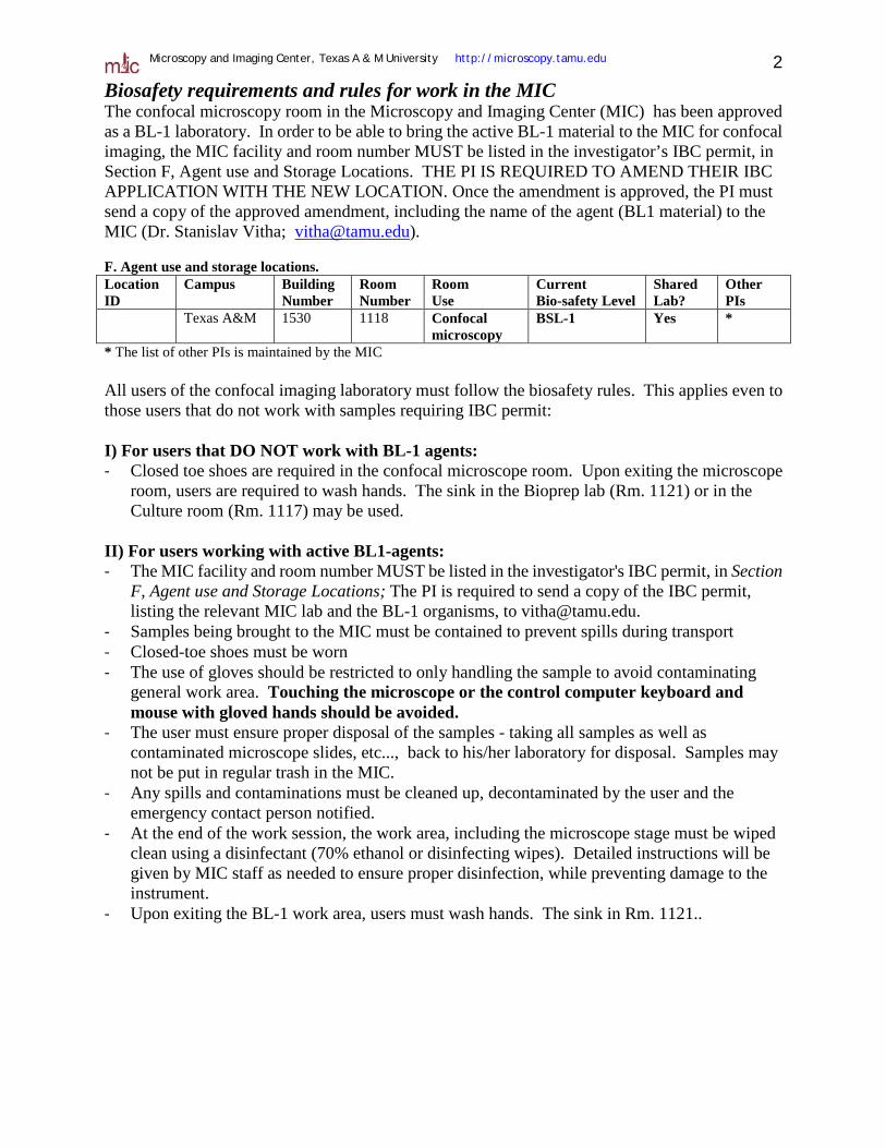
Biosafety requirements and rules for work in the MIC The confocal microscopy room in the Microscopy and Imaging Center (MIC) has been approved as a BL-1 laboratory. In order to be able to bring the active BL-1 material to the MIC for confocal imaging, the MIC facility and room number MUST be listed in the investigator’s IBC permit, in Section F, Agent use and Storage Locations. THE PI IS REQUIRED TO AMEND THEIR IBC APPLICATION WITH THE NEW LOCATION. Once the amendment is approved, the PI must send a copy of the approved amendment, including the name of the agent (BL1 material) to the MIC (Dr. Stanislav Vitha; [email protected]). F. Agent use and storage locations. Location ID
Campus
Building Number
Room Number
Room Use
Current Bio-safety Level
Shared Lab?
Other PIs
Texas A&M 1530 1118 Confocal microscopy
BSL-1 Yes *
* The list of other PIs is maintained by the MIC All users of the confocal imaging laboratory must follow the biosafety rules. This applies even to those users that do not work with samples requiring IBC permit: I) For users that DO NOT work with BL-1 agents: - Closed toe shoes are required in the confocal microscope room. Upon exiting the microscope
room, users are required to wash hands. The sink in the Bioprep lab (Rm. 1121) or in the Culture room (Rm. 1117) may be used.
II) For users working with active BL1-agents: - The MIC facility and room number MUST be listed in the investigator's IBC permit, in Section
F, Agent use and Storage Locations; The PI is required to send a copy of the IBC permit, listing the relevant MIC lab and the BL-1 organisms, to [email protected].
- Samples being brought to the MIC must be contained to prevent spills during transport - Closed-toe shoes must be worn - The use of gloves should be restricted to only handling the sample to avoid contaminating
general work area. Touching the microscope or the control computer keyboard and mouse with gloved hands should be avoided.
- The user must ensure proper disposal of the samples - taking all samples as well as contaminated microscope slides, etc..., back to his/her laboratory for disposal. Samples may not be put in regular trash in the MIC.
- Any spills and contaminations must be cleaned up, decontaminated by the user and the emergency contact person notified.
- At the end of the work session, the work area, including the microscope stage must be wiped clean using a disinfectant (70% ethanol or disinfecting wipes). Detailed instructions will be given by MIC staff as needed to ensure proper disinfection, while preventing damage to the instrument.
- Upon exiting the BL-1 work area, users must wash hands. The sink in Rm. 1121..
Microscopy and Imaging Center, Texas A & M University http://microscopy.tamu.edu 3
Biological Spill Response: BL1 Laborator y
The following procedures are provided as a guideline for biohazard spill clean- up in a BL1 laboratory. Although the biological material in a BL1 level spill should not be a significant health hazard, you have the obligation to minimize the release of recombinant organisms and biohazardous material from the laboratory.
In the event of a spill:
• If a biohazardous material spills on you, remove any contaminated clothing and wash
any exposed body parts. • If a biohazardous material gets in your eyes, flush at the nearest eyewash station. • If the spill area is large or in a common use area, mark, label, or otherwise denote the
area so others may avoid it. • Using materials from your spill kit:
– Put on gloves, lab coat, and eye protection. – Cover the spill with absorbent material. – Pour disinfectant over the entire area. Allow the area to soak for 30 minutes.
• If warranted, contact the principal investigator, assess the magnitude of the spill, and formulate further plans of action.
• Safely pick up any broken glass with forceps or sweep into a dustpan, and dispose the residue into a broken glass/sharps container.
• Place spill materials into an autoclave bag. • Make sure area is cleaned and disinfected thoroughly. • Soak any contaminated clothes and shoes in a tray with disinfectant. • If the spill is greater than 25 ml or contains recombinant DNA, report the spill to the Office of Research Compliance and Biosafety at 979.862.4549.
http://rcb.tamu.edu
Microscopy and Imaging Center, Texas A & M University http://microscopy.tamu.edu 4
USING THE MICOSCOPE
Adjusting the oculars for optimal viewing 1. Adjust the interpupillary distance of the binoculars so that you can see with both eyes 2. Set both oculars to “0” focal correction (see scale on the side of the ocular tube) 3. Use the microscope focus knob to bring the specimen in focus for your left eye. 4. Now, take your hand off the focus knob. Turning the ocular focus correction, bring the
specimen in focus for your right eye.
Precautions when using oil immersion objectives BECAUSE THE DRY 20X AND 40X OBJECTIVES HAVE A VERY SMALL WORKING DISTANCE, THEY MUST NOT BE USED AFTER OIL IMMERSION OBJECTIVES UNLESS ALL OIL NAS BEEN REMOVED FROM THE COVERSLIP. It is OK to use the dry 10x objective after the oil immersion ones, since its working distance is sufficiently large. THE CONFOCAL SOFTWARE MUST BE RUNNING - ONLY THEN IS THE MICROSCOPE SMART ENOUGH TO LOWER THE OBJECTIVES BEFORE TURNING THE OBJECTIVE NOSEPIECE TO NEW POSITION.
Cleaning oil immersion objectives 1. NEVER USE KIMWIPES OR OTHER TISSUE PAPER TO CLEAN OBJECTIVES. USE
ONLY LENS PAPER (e.g. Fisher 11-996) 2. Using clean lens paper gently blot off the oil from the lens. Do NOT drag the paper across the
lens, just dab off the oil. The front lens of the objective is very delicate and must be protected from scratching.
3. Wipe off any oil form the objective barrel. 4. Thorough cleaning of the oil immersion objectives is performed by the MIC staff.
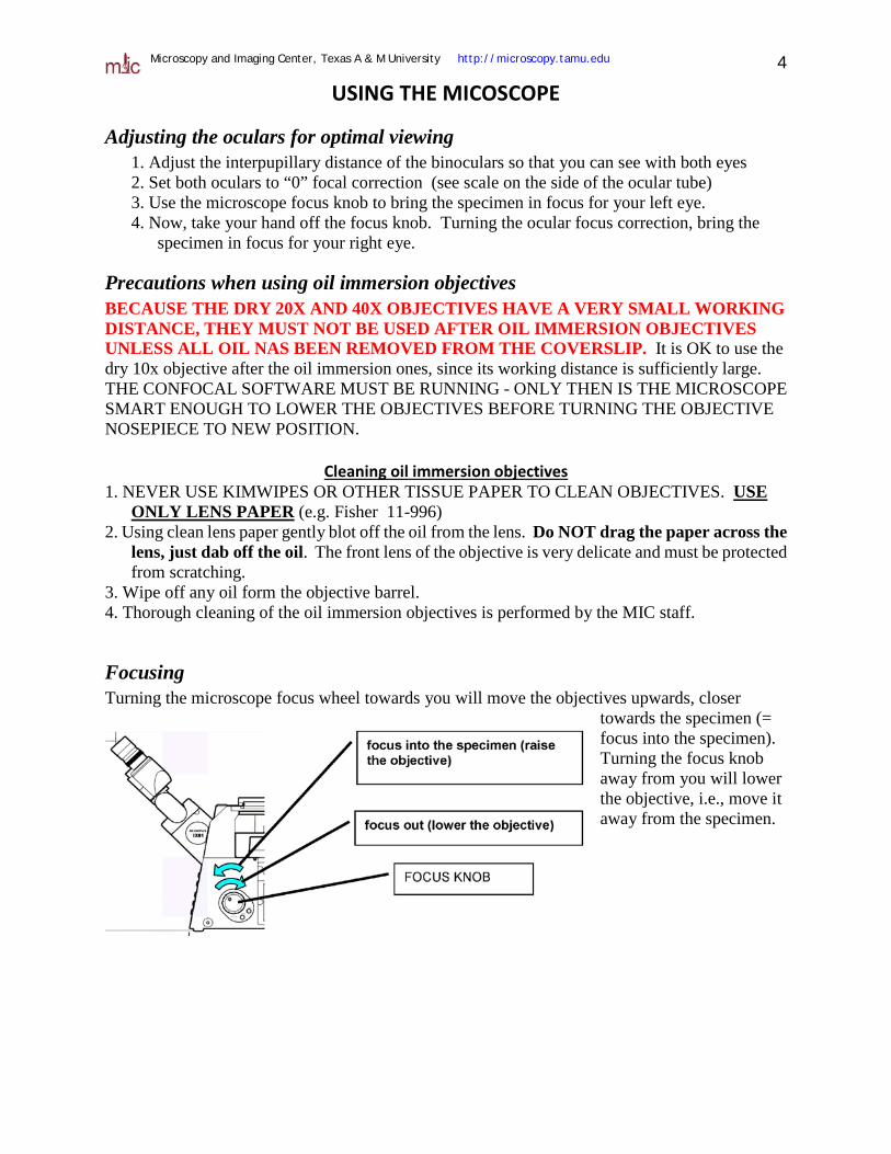
Focusing Turning the microscope focus wheel towards you will move the objectives upwards, closer
towards the specimen (= focus into the specimen). Turning the focus knob away from you will lower the objective, i.e., move it away from the specimen.
Microscopy and Imaging Center, Texas A & M University http://microscopy.tamu.edu 5
Setting up Köhler illumination Kohler illumination produces an even field of illumination and does not show dust and dirt that accumulated on optical surfaces in the illumination path.
1. Place specimen on the stage, turn on the transmitted light (Trans lamp button in the software).
2. Focus the specimen (Fig. 1A). From now on, do not touch the stage focus knob.
3. Completely open the Condenser Aperture (on the condenser) and completely close the Field Aperture (on the arm on top of the plastic enclosure) (Fig. 1B).
4. Move the condenser up or down to focus the edges of the field aperture. The specimen and the Field Aperture must be in focus simultaneously (Fig. 1C).
5. If the Field Aperture is off center, use the two adjusting screws to center the aperture (Fig. 1D).
6. Open the Field Diaphragm until its shadow just disappears from the field of view (Fig. 1E). Opening the Field Diaphragm more than that causes extra glare.
7. Use the Condenser Aperture to change contrast in the transmitted light image – closing the Condenser aperture will provide more contrast but less resolution.
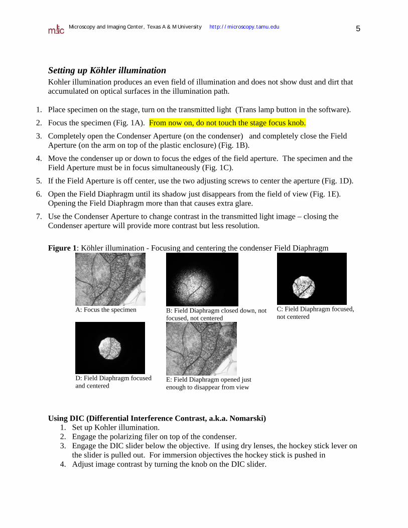
Figure 1: Köhler illumination - Focusing and centering the condenser Field Diaphragm
A: Focus the specimen
B: Field Diaphragm closed down, not focused, not centered
C: Field Diaphragm focused, not centered
D: Field Diaphragm focused and centered
E: Field Diaphragm opened just enough to disappear from view
Using DIC (Differential Interference Contrast, a.k.a. Nomarski)
1. Set up Kohler illumination. 2. Engage the polarizing filer on top of the condenser. 3. Engage the DIC slider below the objective. If using dry lenses, the hockey stick lever on
the slider is pulled out. For immersion objectives the hockey stick is pushed in 4. Adjust image contrast by turning the knob on the DIC slider.
Microscopy and Imaging Center, Texas A & M University http://microscopy.tamu.edu 6
Setting up Confocal Imaging
1. Turn on the needed hardware and start the confocal software (see the Startup/Shutdown procedure).
2. With the lowest-magnification objective (10X dry) engaged, place the slide on the stage, COVERSLIP DOWN (= towards the objective). Click on the trans-lamp button in the software. This will allow you to look at the specimen through the oculars, using transmitted light. Locate the specimen and focus.
3. Adjust Kohler illumination (see next section). This is important if you want to acquire good transmitted- light images in addition to fluorescence images.
4. For Differential Interference Contrast (DIC), the polarizer above the condenser must be engaged. Make sure the DIC slider below the objective turret (below the stage) is also engaged. Turn the knob on the slider for best image. If you do not need DIC imaging, remove the DIC slider from the optical path. This will give you better fluorescence images.
5. If you need to visually inspect the fluorescence of your samples using the mercury lamp illumination, switch to fluorescence mode by clicking on the “Epi-lamp” button in the software. Make sure that the mechanical excitation shutter below the objective nosepiece is open. Choose appropriate filter set using the microscope keypad. The mercury lamp brightness can be adjusted by the aperture lever on the lamp housing. When done with visual inspection of the sample, close the electronic shutter (RSHT button on the keypad) to minimize photobleaching of your sample..
6. In the software, select your dyes from the dye database, or load the imaging conditions from an image saved previously. Adjust the detector HV and offset as needed. As a good starting point with new samples, set your HV to 700 on the fluorescence detectors, laser power to 1% (405nm) 4% (Argon-ion) 20% (HeNe lasers), scan speed (=pixel dwell time) to 8 µs, image size 512 x 512 pixels, confocal zoom 1x. The transmitted detector (TD1) will need much lower HV setting, typically around 100. The GAIN for each detector should not be changed, it should remain at 1x.
7. Start live view using the “Focus 2x” or “Focus 4x” modes and adjust the detector HV and offset to get good image. Use the Ctrl-H key to toggle between pseudocolor and saturation-warning LUT (HiLo lookup table). The goal is to have a very dark background (some blue pixels, by changing the OFFSET) and a minimal amount of saturated pixels (highlighted in red; adjusting the HV) in the area of interest.
8. Adjust the confocal zoom and scan size to achieve desired resolution (click the “i” Information button to see the current optical resolution and pixel size).
If the HV needs to be set much above 700, the images will be noisy. In order to collect more signal from the specimen, use higher numerical aperture objective if possible. Thus, it is better to use a 20x/0.75 objective at confocal zoom 2 than the 10x/0.4 objective at confocal zoom 4. Noise can be also decreased by lowering scan speed, using Kalman filtering (averaging), or increasing the laser power. In samples that are very light-sensitive, you may also need to open the CA (confocal aperture) beyond its optimum setting. This will collect more light, but decrease z-resolution. For very weak signals, better-quality images are obtained in the photon-counting mode.
Microscopy and Imaging Center, Texas A & M University http://microscopy.tamu.edu 7
Setting z-stack start and end positions Turning the focus knob away from you will lower the objective, i.e., move it away from the specimen. For z-stack acquisition, the START is in the lower position of the objective. As the stack is being acquired, the objective is raised each step (moving against gravity), until the END position is reached.
To set z-stack start and end position: 1. In the confocal software, set the desired z-step size. For maximum resolution, the
z-step should be 2-3x smaller than the optical z-resolution. 2. Start Live View (“Focus x2” or “Focus x4” buttons in the software) 3. Focus out (lower the objective) until the object of interest is no longer visible in the
Live View window. 4. Click the “START SET” button in the confocal software to set the START position. 5. Focus into the specimen (raise the objectives) past the object of interest. 6. Click the “END SET” button in the confocal software to set the END position.
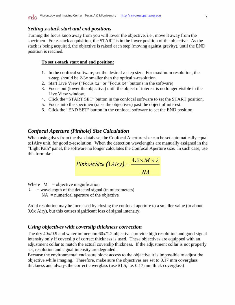
Confocal Aperture (Pinhole) Size Calculation When using dyes from the dye database, the Confocal Aperture size can be set automatically equal to1Airy unit, for good z-resolution. When the detection wavelengths are manually assigned in the “Light Path” panel, the software no longer calculates the Confocal Aperture size. In such case, use this formula:
Where M = objective magnification λ = wavelength of the detected signal (in micrometers)
NA = numerical aperture of the objective Axial resolution may be increased by closing the confocal aperture to a smaller value (to about 0.6x Airy), but this causes significant loss of signal intensity.
Using objectives with coverslip thickness correction The dry 40x/0.9 and water immersion 60x/1.2 objectives provide high resolution and good signal intensity only if coverslip of correct thickness is used. These objectives are equipped with an adjustment collar to match the actual coverslip thickness. If the adjustment collar is not properly set, resolution and signal intensity are degraded. Because the environmental enclosure block access to the objective it is impossible to adjust the objective while imaging. Therefore, make sure the objectives are set to 0.17 mm coverglass thickness and always the correct coverglass (use #1.5, i.e. 0.17 mm thick coverglass)
Microscopy and Imaging Center, Texas A & M University http://microscopy.tamu.edu 8
Multi-color imaging: Sequential mode Use Sequential scanning to minimize spectral overlap (false-positive signal) in multi-color imaging. To test for spectral overlap, turn on live scanning (Focus x 2 or Focus x 4) and turn off the first laser. The first channel window in the live view should go black but no change in image brightness should occur in other channels. If it does, you may need sequential scanning, but first try this:
• On the first (or shorter wavelength) laser try lowering laser power and increase HV in the corresponding detector. Lower intensity laser is less likely to excite dyes that would be detected in the wrong channel. For instance, in DAPI + Cy3 + Cy5 triple staining, lower the 405 laser and increase the HV in the DAPI channel.
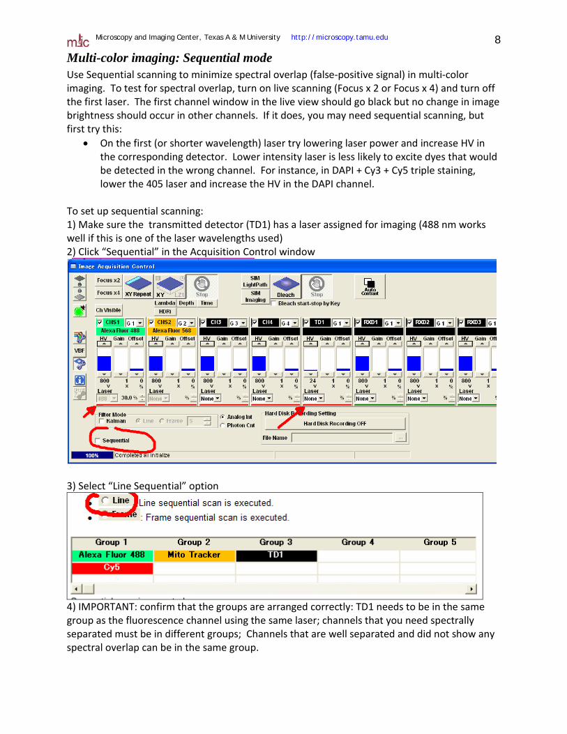
To set up sequential scanning: 1) Make sure the transmitted detector (TD1) has a laser assigned for imaging (488 nm works well if this is one of the laser wavelengths used) 2) Click “Sequential” in the Acquisition Control window
3) Select “Line Sequential” option
4) IMPORTANT: confirm that the groups are arranged correctly: TD1 needs to be in the same group as the fluorescence channel using the same laser; channels that you need spectrally separated must be in different groups; Channels that are well separated and did not show any spectral overlap can be in the same group.

Microscopy and Imaging Center, Texas A & M University http://microscopy.tamu.edu 9
Saving Image Files • By default, your image files are saved in D:\FV10-ASW\users\yourusername\Image.
Create sub-folders there as needed. • There are two native file formats, “.oib” and “.oif”. The .oib format contains everything in a
single large file. In contrast, the .oif format consists of a small text file with imaging parameters and a sub-folder containing the individual images, ROI and LUT info, ...
• When finished, copy your files onto your media (CD ,DVD, USB drive). If you used the .oif format, remember to copy both the “.oif” file and the associated sub-folder containing the actual images. It is recommended that you create two copies of your files to avoid data loss. Once you confirmed that the data are saved on your media without errors, erase the files from the computer.
• Old image files will be purged periodically to free disk space.
Viewing and processing the image files The native file formats (“.oif” and “.oib”) can be opened with the Olympus confocal software (there is a dedicated computer with this software in MIC’s computer room) or with the free Olympus confocal image viewer that can be downloaded from our website (look in the “Instruments” page in the “Olympus confocal” section). Direct reading of confocal datasets and other proprietary formats is possible using ImageJ freeware (http://rsbweb.nih.gov/ij/) or the FIJI distribution of ImageJ (http://fiji.sc/wiki/index.php/Fiji) has this and many other plugins included in the installation package.

Microscopy and Imaging Center, Texas A & M University http://microscopy.tamu.edu 10
Using GaAsP High Sensitivity Detectors (HSDs) These detectors are highly sensitive. Great care must be taken to prevent their damage and degradation of performance. They must be protected from strong light. Use low laser power and always use the Hi-Lo lookup table (saturated pixels highlighted in red). IF THE IMAGE IS SATURATED, QUICKLY LOWER THE HV ON THE DETECTOR AND LOWER THE LASER POWER TO PREVENT DAMAGE. The two HSDs utilize a filter cube to detect two fluorochromes. Three filter cubes are available, for CFP+YFP, GFP+RFP, and Cy3+Cy5 detection. The cubes have to be manually switched if a different pair of fluorochromes is to be imaged with the HSDs. The microscope’s standard detectors still may be used in addition to the new HSDs, allowing thus simultaneous imaging of up to five (more likely four) different fluorochromes.
Installing or replacing the HSD filter cube 1. Make sure the microscope scanning is stopped and the detectors are not in use (confirm that the detectors are not selected in the software, looking in the LightPath panel).
2) Remove the small cover on the HSD unit. 3) Loosen the locking screw at the base of the cube mount (bottom right side). A half-turn should be enough. Grab on the handle and pull out the cube
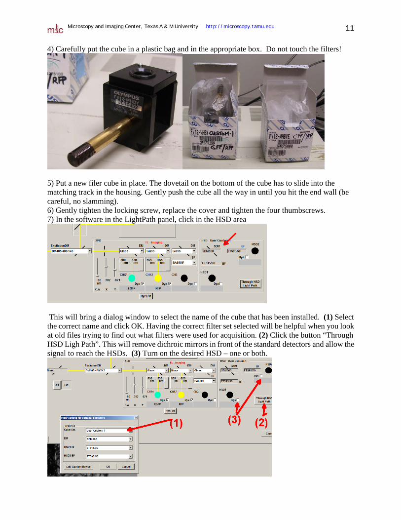
Microscopy and Imaging Center, Texas A & M University http://microscopy.tamu.edu 11 4) Carefully put the cube in a plastic bag and in the appropriate box. Do not touch the filters!
5) Put a new filer cube in place. The dovetail on the bottom of the cube has to slide into the matching track in the housing. Gently push the cube all the way in until you hit the end wall (be careful, no slamming). 6) Gently tighten the locking screw, replace the cover and tighten the four thumbscrews. 7) In the software in the LightPath panel, click in the HSD area
This will bring a dialog window to select the name of the cube that has been installed. (1) Select the correct name and click OK. Having the correct filter set selected will be helpful when you look at old files trying to find out what filters were used for acquisition. (2) Click the button “Through HSD Ligh Path”. This will remove dichroic mirrors in front of the standard detectors and allow the signal to reach the HSDs. (3) Turn on the desired HSD – one or both.
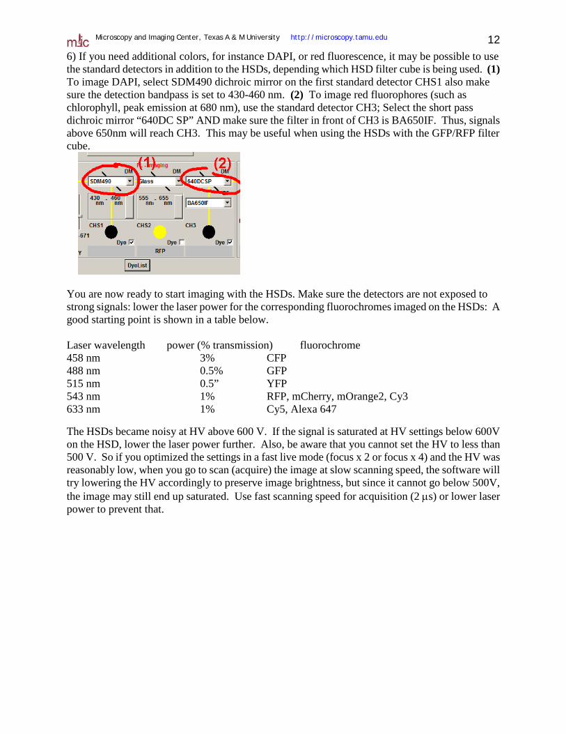
Microscopy and Imaging Center, Texas A & M University http://microscopy.tamu.edu 12 6) If you need additional colors, for instance DAPI, or red fluorescence, it may be possible to use the standard detectors in addition to the HSDs, depending which HSD filter cube is being used. (1) To image DAPI, select SDM490 dichroic mirror on the first standard detector CHS1 also make sure the detection bandpass is set to 430-460 nm. (2) To image red fluorophores (such as chlorophyll, peak emission at 680 nm), use the standard detector CH3; Select the short pass dichroic mirror “640DC SP” AND make sure the filter in front of CH3 is BA650IF. Thus, signals above 650nm will reach CH3. This may be useful when using the HSDs with the GFP/RFP filter cube.
You are now ready to start imaging with the HSDs. Make sure the detectors are not exposed to strong signals: lower the laser power for the corresponding fluorochromes imaged on the HSDs: A good starting point is shown in a table below. Laser wavelength power (% transmission) fluorochrome 458 nm 3% CFP 488 nm 0.5% GFP 515 nm 0.5” YFP 543 nm 1% RFP, mCherry, mOrange2, Cy3 633 nm 1% Cy5, Alexa 647 The HSDs became noisy at HV above 600 V. If the signal is saturated at HV settings below 600V on the HSD, lower the laser power further. Also, be aware that you cannot set the HV to less than 500 V. So if you optimized the settings in a fast live mode (focus x 2 or focus x 4) and the HV was reasonably low, when you go to scan (acquire) the image at slow scanning speed, the software will try lowering the HV accordingly to preserve image brightness, but since it cannot go below 500V, the image may still end up saturated. Use fast scanning speed for acquisition (2 µs) or lower laser power to prevent that.
Microscopy and Imaging Center, Texas A & M University http://microscopy.tamu.edu 13
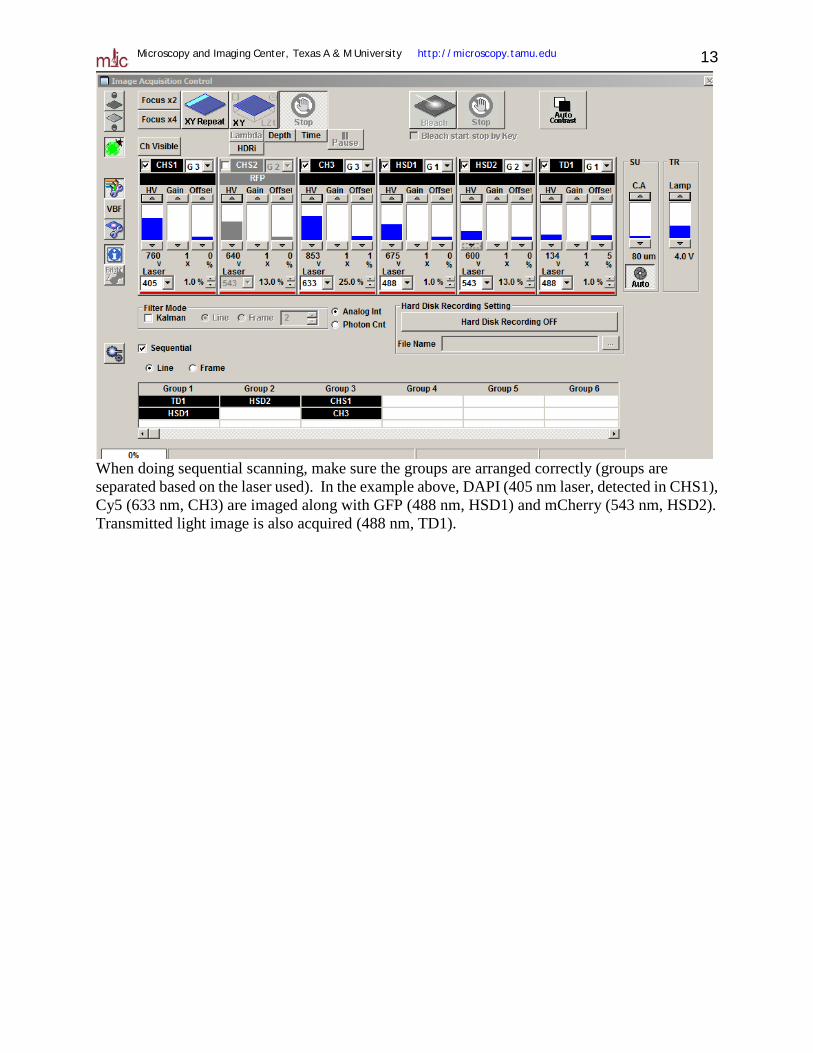
When doing sequential scanning, make sure the groups are arranged correctly (groups are separated based on the laser used). In the example above, DAPI (405 nm laser, detected in CHS1), Cy5 (633 nm, CH3) are imaged along with GFP (488 nm, HSD1) and mCherry (543 nm, HSD2). Transmitted light image is also acquired (488 nm, TD1).
Microscopy and Imaging Center, Texas A & M University http://microscopy.tamu.edu 14
STARTUP PROCEDURE
1. Fill out the user log sheet
2. Set the power switches of the following units to I (ON). • Mercury Burner Power Supply (only if needed) • Main confocal controller (also turn the key to “ON “ position) • SIM Scanner controller (only if needed). • Microscope Control Box IX2-UCB • Prior stage controller
3. Turn ON the computer
4. Turn on the lasers: - only the lasers that are needed for your sample
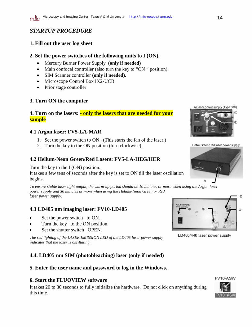
4.1 Argon laser: FV5-LA-MAR 1. Set the power switch to ON. (This starts the fan of the laser.) 2. Turn the key to the ON position (turn clockwise).
4.2 Helium-Neon Green/Red Lasers: FV5-LA-HEG/HER Turn the key to the I (ON) position. It takes a few tens of seconds after the key is set to ON till the laser oscillation begins. To ensure stable laser light output, the warm-up period should be 10 minutes or more when using the Argon laser power supply and 30 minutes or more when using the Helium-Neon Green or Red laser power supply.
4.3 LD405 nm imaging laser: FV10-LD405 • Set the power switch to ON. • Turn the key to the ON position. • Set the shutter switch OPEN. The red lighting of the LASER EMISSION LED of the LD405 laser power supply indicates that the laser is oscillating.
4.4. LD405 nm SIM (photobleaching) laser (only if needed)
5. Enter the user name and password to log in the Windows.
6. Start the FLUOVIEW software It takes 20 to 30 seconds to fully initialize the hardware. Do not click on anything during this time.

Microscopy and Imaging Center, Texas A & M University http://microscopy.tamu.edu 15
SHUTDOWN PROCEDURE
1. Clean the work area and objectives (if immersion was used).
2. Switch to the lowest-magnification dry objective (10x) before exiting from the confocal software
3. Exit from the software • Exit from the Fluoview software • After exiting the application software, the light of mercury burner power supply unit may
expose the specimen. To avoid this, close manual shutter on the microscope fluorescence filter turret (below the objectives).
• Save your data on (CD, DVD, USB drive, …). • Shut down Windows.
4. Turn the power off: The Argon ion and HeNe laser life is shortened by frequent turning on and off. Therefore, leave these lasers ON during the day and turn it off only if you are the last user of the day.
1. 405 nm diode lasers if they were on.
2. Red and green HeNe lasers - TURN OFF ONLY IF YOU ARE THE LAST USER FOR THE DAY
3. Argon laser: TURN OFF ONLY IF YOU ARE THE LAST USER FOR THE DAY. IF NOT, LEAVE THE ARGON LASER RUNNING FOR THE NEXT USER.
• Turn the key to OFF position • WAIT!! The laser must cool down. The fan to stop automatically when the
laser unit has cooled down. It takes several minutes • Set the power switch to OFF.
4. Microscope Control Box IX2-UCB
5. Prior stage controller box
6. Main confocal controller
7. SIM scanner controller (if it was on)
8. Mercury Burner Power Supply Unit
5. Sign off in the user log sheet and cover the microscope with the plastic cover