oilmater separation - infohouseinfohouse.p2ric.org/ref/29/28243.pdf · oilmater separation paul n....
TRANSCRIPT

Oilmater Separation PAUL N. CHEREMISINOFF, P.E. Editor, TNEJ
Many industries discharge liquid wastes contaminated with hydrocarbon or oil-like pollutants. Sources of such waste include refining and processing petroleum and petrochemicals, metal fabricating waste, utility operations, sanitary sewage, bilge and ballast wastes, and contaminated surface runoff. The total quantity of such oil waste generated in the United States alone has been estimated in excess of one billion gallons per year.
Oil discharges into the environment typically have deleterious effects. Oily waste discharges may have objection- able odors and undesirable appear- ances. They may burn on the surface of receiving waters, creating potential safety hazards and consuming dis- solved oxygen necessary to aquatic life. Oils in drinking water sources cause objectionable taste and odors, turbidity, and film, making filtration treatment dif- ficult. Bioassay data indicate that oil is toxic to fish; in sub-acute levels, oil taints fish and shellfish taste. It also lim- its oxygen transfer, hindering biological activity. Floating puddles of oily waste entrap waterfowl, damage watercraft, and wash up on recreational beaches.
Federal, state, and some local regu- lations have established standards for the discharge of wastewaters contain- ing oily residues. Standards vary from specific mg/l limits to qualitative stan- dards requiring, for example, that the wastewater have no visible sheen.
Oil in Water Oil can exist in water in several forms. Free oil rises quickly to the water sur- face when given a short quiescent set- tling period. Mechanical dispersions are distribu- tions of fine oil droplets ranging in size from microns to fractions of a millime- ter and having stability due to electri- cal charges and other forces, but not
due to the presence of surface active materials. Chemically stabilized emulsions are distributions of oil droplets similar to mechanical dispersions, but which have additional stability due to chemi- cal interactions typically caused by sur- face active agents present at the oil/water interface. Dissolved oil is either dissolved in a chemical sense, or dispersed in such fine droplets (typically less than 5 microns) that removal by normal phys- ical means is impossible. Oil that adheres to the surface of particulate materials, is referred to as oil-wet solids. The degree of an oillwater separation
problem depends on the oil particulate size distribution. Separation problems also involve chemicals other than oil, which have an effect on treatment required. Oil spills, leaks, and points of contamination should be contained. If possible, oil-laden wastes should be treated in their most concentrated state -at their source. To limit the dispersion of entrained oil, centrifugal pumps and other equipment that have strong shear- ing forces should not be used. To limit chemical emulsification, wastes contain- ing surface active agents should not be mixed with other oil-laden wastes.
Oily wastewater is similar in many respects to the treatment of domestic sewage. In domestic sewage treatment, a primary level of treatment is employed to separate the easily settleable solids from the wastewater. In the treatment of oily wastewaters, a primary treatment is used to separate the floatable free oils from the dispersed, emulsified, and sol- uble fractions. Primary treatment is also used to remove oil-wet solids. Common primary separation devices use sedi- mentation, flotation, and centrifugation related techniques. Secondary treatment is then used to break oil/water emulsions and to remove dispersed oil. Technology typically consists of chemical treatment and filter coalescence. Tertiary treatment includes ultrafiltration, biological treat- ment, and carbon adsorption.
Gravity Separation Gravity separation, the primary and
most common treatment, is based on the specific gravity difference between water and immiscible oil globules, and is used to move free oil to the surface of a water body for subsequent skimming and removal. The American Petroleum Insti- tute (API) has specified design criteria for simple gravity separators based on the removal of free oil globules larger than 0.01 5 cm (1 50 microns) in diameter.
The effectiveness of a gravity separa- tor depends on the proper hydraulic design and the period of wastewater detention for a given rise velocity. Longer retention times generally increase sepa- ration efficiency. Effective removal of oil droplets with a given rise velocity is a function of the system geometry. The liq- uid detention must be sufficient to permit oil droplets rising at a given velocity to come to the fluid boundary where they can be removed by skimming.
API Separator Criteria API separator design criteria control
the velocities within the unit by specify- ing that:
The horizontal velocity through the separator may be up to 15 times the rise velocity of the critical (i.e., slowest rising) oil globule, up to a maximum of 3.0 feet per minute. Above this limit, the effect of turbulence tends to redis- tribute oil droplets. The depth of flow in the separator should be within 3.0 to 8.0 feet. This limits the height that must be traversed by a rising oil globule. The width of the separator should be between 6.0 and 20.0 feet. The depth-to-width ratio should be between 0.3 and 0.5. An oil retention baffle should be locat- ed no less than 12 inches downstream from a skimming device
HORIZONTAL CORRUGATED PLATE DESIGN
Figure 1 : Gravity Separation Schemes
32 The National Environmental lournal May/June 1993
WASTE REDUCTION Q & A w e use an ultrafiltration membrane to separate our oil/water emulsions. Every few days the membranes clog up and won't work well. Is there a simple cleaning method?
On a daily basis follow a simple two-step routine to maintain your membranes. Step 1-use liquid laundry detergent, mix 1
solids numbers using my conductivity meter?
Calibrate Conductivity Meter:
74.264 grams reagent grade potassium chloride and dis- solving in 1 liter of deionized water.
B. Make a 1:lOO dilution of solution A with deionized water. C. Immerse the conductivity electrode in solution B. D. Adjust the CELL ADJ control to read 1.41. Procedure: 1. Read and record conductivity of the city water.
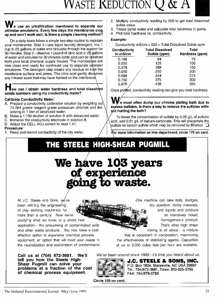
2. Multiply conductivity reading by 500 to get total dissolved solids value.
3. Titrate same water and calculate total hardness in ppms. 4. Plot total hardness vs. conductivity.
Example: Conductivity mS/cm x 500 = Total Dissolved Solids ppm
Conductivity Total Dissolved Total in mS/cm Solids (ppm) Hardness (ppm) 0.1 88 94 75 0.250 125 100
188 150 250 200
0.376 0.500 0.688 /" 344 275
/
s sulfates. Is there a way to remove the sulfates with- t hurting the bath?
Waste. At J.C Steele and Sons, w 've One machine can take soils, sludges, been refining the engineering ,/k dry powders, sticky materials, of clay working machinery for and liquids and produce more than a century Now we're an intensively mixed,
application - the processing of contaminated so' That's what high shear and other waste products. You now have a co mixing is all about - a mixture effective option to expensive chemical process that is consistent in composition, maximizing equipment; an option that will meet your needs in the effectiveness of stabilizing agents. Capacities the neutralization and stabilization of contaminants. of up to 2,000 cubic feet per hour are available.
applying what we k n ~ w tc a whde new hG"eneC?us product.
I Call us at (704) 872-3681. We'll We've been around since 1889 - it's time you heard about us. tell you how the Steele High- Shear Pugmill can solve your problems at a fraction of the cost
J.C. STEELE & SONS, INC. P.O. Box 1834, Statesville, NC USA 28687 Tel.: 7041872-3681, Telex: 810-625-0795
of chemical process equipment. FAX: 7041878-0789
I Circle 129 on card.
The National Environmental Journal May/ June 1993 31

Gravity separation often includes a provision for heating to lower the viscos- ity and extended plate surfaces (to decrease the effective rise height that must be traversed by a rising oil globule). This latter effect is illustrated in Figure 1. Common separator designs using a gravity differential as the primary force include those based on the above described API design criteria, CPI (cor- rugated plate interceptor) and PPI (par- allel plate interceptor) units. Careful handling of flows in a gravity separator by these methods often permits separa- tion of oil droplets finer than those of free oil.
FLOCCULATION FLOTATION -CLARIFIED CHAMBER CHAMBER EFFLUENT
Flotation Devices
FLOCCULATION CHAMBER
Flotation devices use the gravity sep- aration concept and are more effective than sedimentation devices in removing dispersed oil because the buoyancy dif- ferential is increased by attaching small air bubbles to the slow rising oil globules. One use of air flotation equipment is in the treatment of oil-wet solid laden wastes. Coagulant aids, such as poly- electrolytes, are commonly used to pro- mote agglomeration of the oil-bearing matter into large flocs that are more eas- ily removed. Air flotation devices are usually preceded by one of the gravity separation techniques described above to remove gross quantities of free oil and settleable solids. This reduces the required volume of dissolved air and floc- culating chemicals to economical levels.
Two methods are commercially used to form the minute air bubbles. One involves aerating the waste to saturate it with air at atmospheric pressure, releas- ing the excess air, and then forming the small bubbles by applying a vacuum of approximately 9 inches of mercury. In the other method, air is dissolved into the waste under two to three atmospheres of pressure before the pressure is released, forming the minute bubbles. The latter method is more common in the treatment of oily wastes. There are three variations of this latter method, full-flow, split-flow, and recycle operation.
In full-flow operation, shown in Figure 2, the entire waste stream is saturated under pressure, followed by the subse- quent release of pressure and bubble for- mation at the inlet to the flotation chamber. This scheme offers several advantages.
It provides maximum gas solution at any particular pressure, thereby achieving maximum bubble formation and bubble contact. For equal flow rates, a small flotation chamber is required. However, this orientation requires a
CLARIFIED FLOTATION CHAMBER EFFLUENT
pressurizing pump large enough to han- dle the full waste flow, and the raw waste, which may be loaded with solids, must pass through the pressurizer.
Split-flow operation, shown in Figure 3, consists of pressurizing and dissolving air in only part of the waste flow and divert- ing the remainder directly into the flota- tion chamber, where it is mixed with the pressurized fraction. Split-flow operation uses a smaller pressurizing pump than full-flow operation, reduces the amount of emulsion that might be formed by the pressurizing pump, and relies on a small flotation chamber.
Recycle operation, depicted in Figure 4, consists of pressurizing and dissolving the air recycle stream of clarified effluent. The pressure is released and the bubble- containing recycle stream is mixed with the wastewater influent flow. The recy- cled stream usually is 20 to 50 percent of
WASTE -@ FLOCCULATING
AGENT
AIR ,___....._.
the influent flow. This system uses the smallest pressurizing pump and operates the pressurization at a constant flow rate. It minimizes emulsion formation and plug problems by pressurizing clear effluent. In systems incorporating flocculation, it tends to disintegrate the floc by the shearing action of the pressurization pump.
______
Centrifugal Separators In this technique, the more dense
water phase is moved to the outer region rotating volume of fluid. The lighter oily materials collect near the vortex and are subsequently removed. This requires that the oil-collecting mechanism must be designed to remove a small column of oil at the center line if it is to be effective in oil-in-water emulsions. The maximum benefit of centrifugal forces is realized at
t OILY SCUM
CLARIFIED FLOTATION EFFLUENT CHAMBER
PRESURE RETENTION
TANK
Figure 2: Full-Flow Air Flotation
f OILY SCUM
AGENT I I AIR I....____...
FLOCCULATING
L*LF0".l PRESURE
RETENTION TANK
Figure 3: Split-Flow Air Flotation
f OILY SCUM I
I FLOCCULATING AGENT
-. . . . .,
PRESSURE RETENTION '0 TANK
I AIR I w RECYCLE PUMP
Figure 4: Recycle-Flow Air Flotation
The National Environniental Journal May/ June 1993 33

the outer radial regions, apart from the small column of separated oil. For these reasons, centrifugal separators have found limited use in the treatment of oil- in-water emulsions, but have found wide- spread use in the treatment of water-in-oil emulsions. A modification of the basic centrifuge, which incorporates parallel plates to provide laminar flow regions, has been found effective in treat- ing dispersed oil. Effluent qualities aver- aging 50 to 70 parts per million (ppm) of oil are reported.
Emulsification Processes used to break oil/water
emulsions include chemical, electrical, and physical methods. Chemical meth- ods are in widest use. The electrical process is directed toward emulsions containing mainly oil, with small quanti- ties of water. Physical emulsion breaking methods include heating, high speed centrifugation, and precoat filtration. Chemical treatment of an emulsion destabilizes the dispersed oil droplets or chemically binds or destroys any emulsi- fying agents present. Chemical demulsi- fying processes include acidification, coagulation, salting out, and demulgation with organic cleaving agents.
Acids generally cleave emulsions
more effectively than coagulant salts, but are more expensive and the resultant wastewater must be neutralized after the separation. Salting out of an emulsifier is achieved by adding large quantities of an inorganic salt, thereby increasing the dis- solved solids content of the water phase. Coagulation with aluminum or iron salts is generally effective, and is in common use even though the resultant hydroxide
the reusability of the recovered oil. Organic demulgators are extremely
effective demulsifying agents, but are generally very expensive and special- ized. Two modes of operation include adding a specific chemical agent with sufficient properties to neutralize any other charges that inhibit coalescence, or chemically reacting with and/or breaking down the specific chemical species causing the emulsification. Chemical demulgators are normally considered only if effective in low con- centrations, due to their cost, and in many cases, their toxicity at higher con- centrations. Demulsification is normally followed by sedimentation or flotation for removal of the destabilized oil.
Breaking the emulsion into separate surface active properties tends to alter the surface wetting properties of the coalescing fibers, which usually lends to “poisoning” of the media. In addition, the effectiveness of the system depends, among other things, on the mechanical forces of the influent pass- ing through the filter. If the volume and/or force of the pumping i s too great, the oil droplets tend to be prema- turely carried into the mainstream flow, and are insufficient in size to gravity- separate from the effluent. Despite these drawbacks, filter coalescers are quite effective. The effluent quality achievable with such devices is in the range of 1 to 50 ppm oil depending on the surfactant content, loading condi- tion, and oil type.
Coalescing media used for oil sepa- ration vary in the materials used and the effective pore size. In some coa- lescing media, a fibrous material such as nylon or propylene is wound about a rigid spool to form a cartridge. The tigh- ness of the wrap and the fiber diameter largely control the effective porosity for these devices. Other coalescing media incorporate the use of tightly woven or tightly wrapped sheets of fiberglass. Since coalescing media does tend to plug with particulates, less costly pleated-paper type elements are often used as coalescing media or as pre- filtration media.
Reticulated polyurethane foams have come into use as coalescing media.
sludges are difficult to dewater, and limit ~~
~
Circle 130 on card. 34 May/June 1993

These foams are natural sorbents, are light in weight, are relatively inexpen- sive, and can be molded in such a man- ner as to readily control effective pore size. In most cases, the separators incorporating coalescence are designed for the replacement of the media once it is poisoned, plugs, or otherwise fails.
The geometry and orientation of coa- lescing elements in separator devices varies from one design to another. Most manufacturers use long, relatively small-diameter cartridges of a standard size, and stack these in parallel to han- dle the required throughput. Several stages of these groupings operating in series are often used to achieve a greater degree of removal and to act as a built-in backup. The media is normally installed vertically or horizontally, depending upon the design. Horizontal orientation normally decreases the effective oil droplet rise height. How- ever, this design is normally more diffi- cult and time consuming to service since the entire vessel must be com- pletely drained before opening.
Biotechnology The treatment of dissolved oils and
other types of chemically stabilized emul- sions that cannot be destabilized by chemical additions can pose serious problems. Biological treatment with accli- mated microorganisms is generally effec- tive in degrading much of this material, and is commonly used in petroleum refineries and rendering plants. Howev- er, the systems are only effective if suit- able pretreatment and high dilution can be achieved. Too much oil is a problem in biological systems because it is adsorbed by the microorganisms faster than it can be metabolized.
In trickling filters, oil tends to coat the microbial surfaces and reduce the trans- fer of more readily oxidizable organics. In activated sludge systems, the adsorbed oil tends to impair sludge settling chart- tacteristics. Resulting sludge losses may be so high as to reduce the microbial level in the system enough to cause reduced efficiency and possible systern failure.
The microbial metabolism of oil is lim- ited by the low solubility of oil, the chem- ical configuration of oil molecules, and the microbial surfaces. Trickling filters can treat oil concentrations of up to 100 ppm with no effect. Activated sludge sys- tems show no effect if the oil concentra- tion is kept less than 25 ppm. Biologically treated effluents typically contain less than 10 ppm of oil.
Selection of the optimum biological waste treatment process for a particular waste is complex. Many factors are
involved, including economics, land avail- ability, and effluent quality required. Bench-scale testing is also useful in determining the toxic limit of the oily con- taminant. It should be realized, however, that the oxygen transfer rates and the sludge separationheturn efficiencies in pilot systems are higher than the rates in a full-scale system and must be com- pensated for in scale-up.
Carbon Adsorption Carbon adsorption has been used
extensively as a means of removing
trace quantities of oil. Treatment requires a suitable means of regenerating the car- bon. Methods that have been addressed include steam, hot water, organic sol- vents, and pyrolysis. Treatment by car- bon adsorption also generally requires a large capital investment for carbon inven- tory and regeneration equipment and has, therefore, not found widespread use in oil separation where high concentra- tions are involved.
.. --
Ultrafiltration Ultrafiltration is based on the sieving
Circle 131 on card.
The National Environmental Journal May/ June 1993 35

action of a polymeric membrane con- trolling the flow of molecules larger than the membrane pores. Applied pressure is used to increase the flux of the liquid across the membrane. The membranes tend to foul with particulates and the flux therefore decreases. The fouling is normally removed by back flushing and/or detergent washing. Reverse osmosis is similar to ultrafiltration in that an applied pressure forces the water through the membrane against a con- centration gradient, while oil is retained due to the small size of the membrane pores. However, in reverse osmosis, the pore sizes are smaller and the applied pressures are significantly higher. These treatments can be used to produce essentially oil-free effluents, but require large capital investment and have high operating costs.
In selecting the appropriate separator equipment, the specifics of the oily waste problem should be carefully stud- ied. The characteristics of the oily water mixture should be determined after all reasonable water management tech- niques have been instituted. Typical characteristics that should be deter- mined include the oil and bulk fluid den-
sities, the oil rise velocity, the oil droplet size distribution, the presence of emul- sifying agents, and the suspended solids content and distribution. Every effort should be made to treat the waste in its most concentrated form and to prevent contamination with particulates and chemical emulsifiers. Low shear positive displacement pumps should be used to prevent shear of the fluid. If the oil is present in quantities greater than roughly 1 percent, gravity separation or similar methods should be used to achieve bulk separation. If chemical emulsions are present, they should be treated before contacting coalescer media. De-emulsifying agents should be evaluated by jar testing. Prefiltration should be used to increase coalescer life when applicable.
It may be necessary to install a sepa- ration system for a specific separation problem. In such cases, the available off-the-shelf components can be added together in series to meet the require- ments of the specific situation. A sepa- ration system may well consist of gravity separation, emulsion breaking, flocculation assisted air flotation, pre- filtration, and filter-coalescence. 0
FAILURE ANALYSIS, CONSULTING, LAB TESTING, FIELD SERVICES
Discover the benefits Tanks, PipingFittings, Pressure of our materials Inspection/lnstrumentation
TANKS 81 PIPING UST, AST, Septic
Vessels, Integrity Tests, Field
technology problem- solving experience. I GEOSYNTHETICS Product Evaluation,
Stress Analysis, Chemical Exposure Testing MATERIALS Mech. Property Tests,
Long Term Durability FRACTURE Failure Analysis, Fracture Analysis, Forensics DESIGN CAD, Finite Elements, Experimental Stress Analysis
L. J. Broutman & Associates, Ltd. 3424 S. State St., Chicago, IL 60616
Fax 31 2 842 3583
s Arro ]op tnr l .""" " U."U, Aninn .y"'..J, Finnnr I "1Y"' Printinn ," 'L" 'y ,
For capabilities literature please call:
31 2-842-4100
POWE~GEAR Custom-Built Stabilizing Systems. A complete hydraulic stabilizing system that lifts, levels, and locks your equipment in place for field operation. Power Gear Stabilizing Systems offer:
No exposed rod-chrome piston rod is never exposed to outside elements. Weight savings-70,000-lb. capacity leg with lock valves and shoe weighs approximately 250 Ibs. Lifting capacities from 10,000 Ibs. to 70,000 Ibs. per leg Full range of controls: 12VDC; 24VDC: 110VAC; PTO; or air-operated.
Call: 1-800-334-4712.
950 Green Valley Rd.. Beaver Dam, WI 53916
Circle 134 on card.
Largest Mfg. of Fiberglass OillWater Separators
AFL's VERTICAL TUBE COALESCING OWWATER SEPARATOR (VTCTM). Guaranteed Performance: (1) removal of oil globules down to 20-micron size (2) reduction of oil content to 10 mg/ltr. The VTC removes even non-permanent mechanically emulsified oil. It leaves novisiblesheen and trapssolidstoo. In metalworking and similar applications, it removes up to 99 percent of tramp oils from coolants. Units are available for above or below grade applications. Complete line of sizes and options to meet your needs. HINGED COVERS 1 FlR OUlLEl
ML SKIMMfR CUlLEl
VTC-Io :OLDED CORROSiON RESISTANT FIBERGIASS ENVELOA
3661 West Blue Heron Blvd. Riviera Beach, Florida 33404 Telephone: (407) 844-5200 Fax: (407) 844-5246
Circle 132 on card. Circle 133 on card.
36 The National Environmental Journal May/June 1993