mechanical separation techniques · separation techniques 1. solid-solid separation dry methods...
TRANSCRIPT
MECHANICAL SOLID-SOLID SEPARATION TECHNIQUES
1
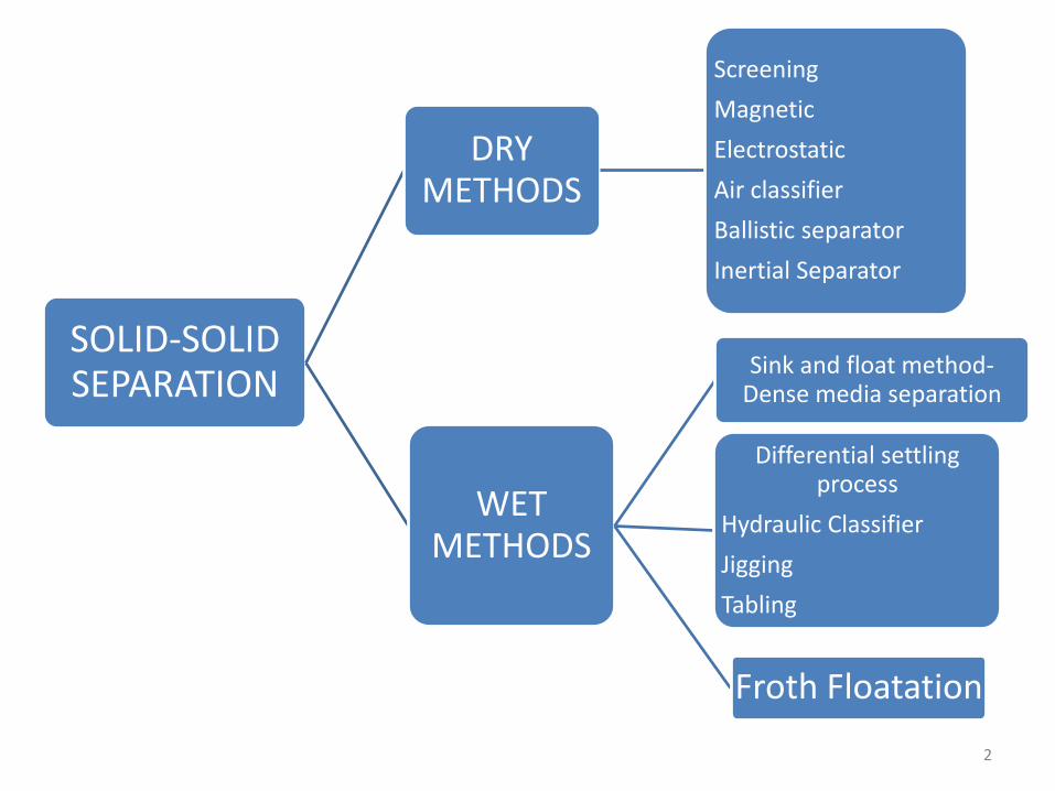
SOLID-SOLID SEPARATION
DRY METHODS
Screening
Magnetic
Electrostatic
Air classifier
Ballistic separator
Inertial Separator
WET METHODS
Sink and float method-Dense media separation
Differential settling process
Hydraulic Classifier
Jigging
Tabling
Froth Floatation
2

SCREENING
3

4

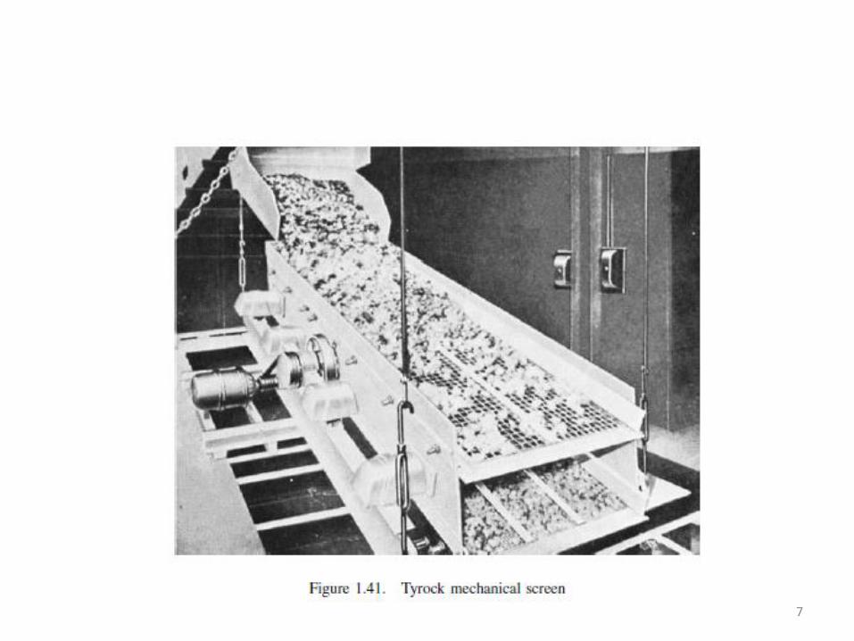
Mechanically vibrated Horizontal screen Hummer Electromagnetic screen
5
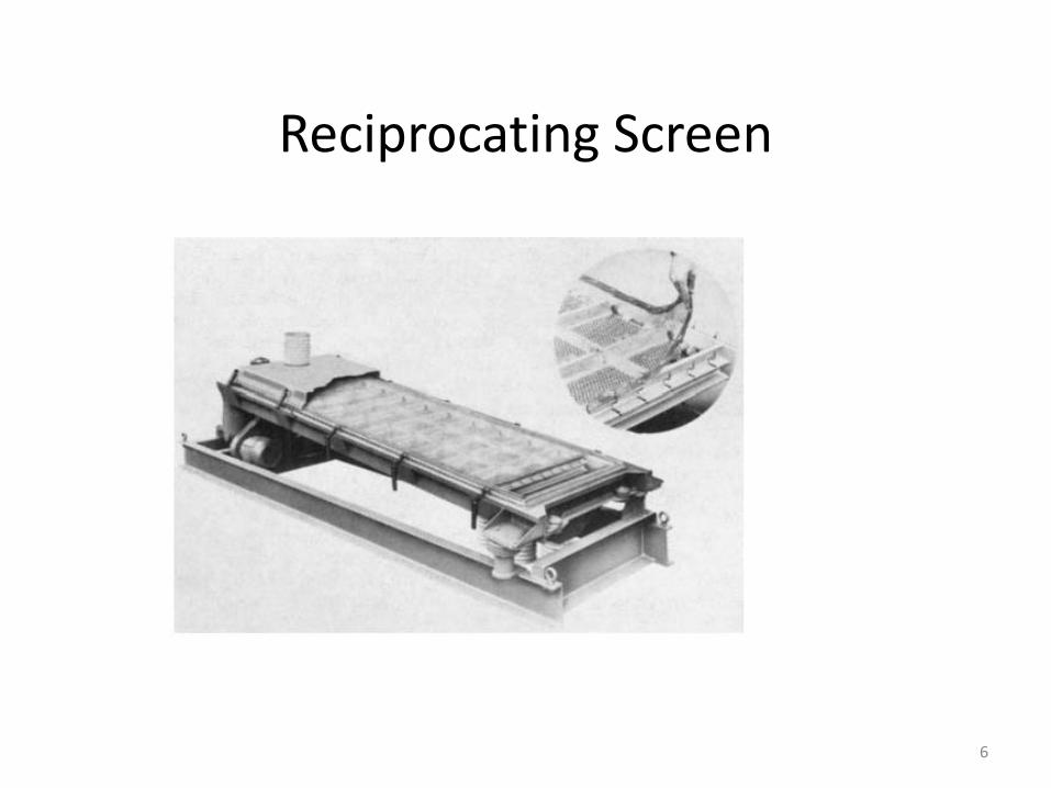
Reciprocating Screen
6
7
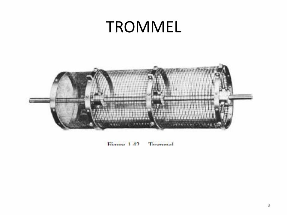
TROMMEL
8
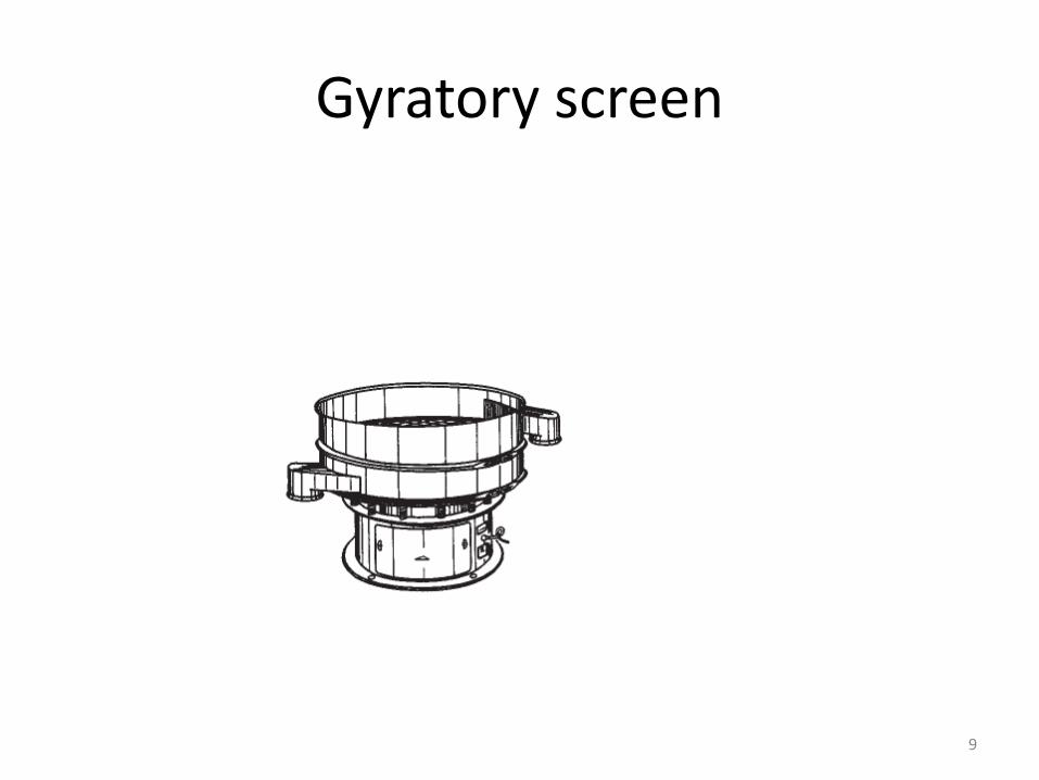
Gyratory screen
9
Magnetic Separation
10
MAGNETIC SEPARATIONBased on magnetic behavior matrial can be classified as”
1. Ferromagnetic – very strong magnetic susceptibility- iron, nickel and cobalt.
2. Paramagnetic – weak magnetic susceptibility –a) Weakly magneticb) Strongly magnetic
3. Diamagnetic particles – repelled by magnet4. Non magnetic
Principle of operation : Passing material through Magnetic field which can be produced by:
1. Permanent magnet2. Electromagnet – where, intensity of magnetic field cam be varied by
varying the current, and a much higher intensity can be reached
APPLICATION 1. Tramp iron removal2. Concentration and purification
11
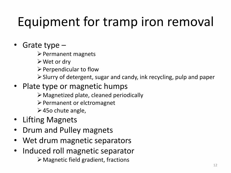
Equipment for tramp iron removal
• Grate type –Permanent magnets Wet or dryPerpendicular to flowSlurry of detergent, sugar and candy, ink recycling, pulp and paper
• Plate type or magnetic humpsMagnetized plate, cleaned periodicallyPermanent or elctromagnet45o chute angle,
• Lifting Magnets• Drum and Pulley magnets• Wet drum magnetic separators• Induced roll magnetic separator
Magnetic field gradient, fractions 12
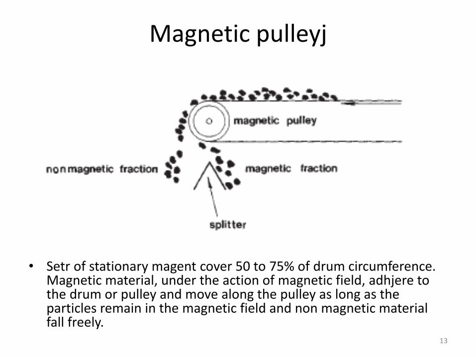
Magnetic pulleyj
• Setr of stationary magent cover 50 to 75% of drum circumference. Magnetic material, under the action of magnetic field, adhjere to the drum or pulley and move along the pulley as long as the particles remain in the magnetic field and non magnetic material fall freely.
13
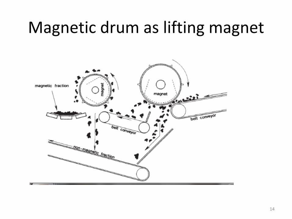
Magnetic drum as lifting magnet
14
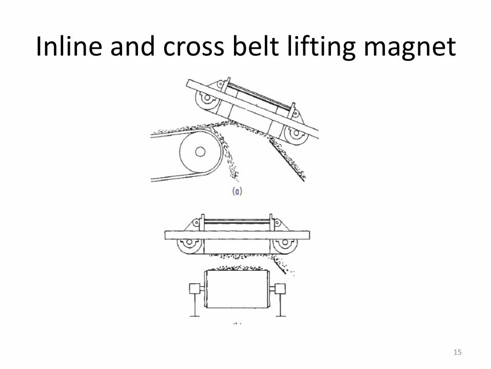
Inline and cross belt lifting magnet
15

Magnetic drum operating as pulley
• Drums of 0.3 to 0.6 m diameter and 0.3 to 1.5 m width.• May be wet or dry
16
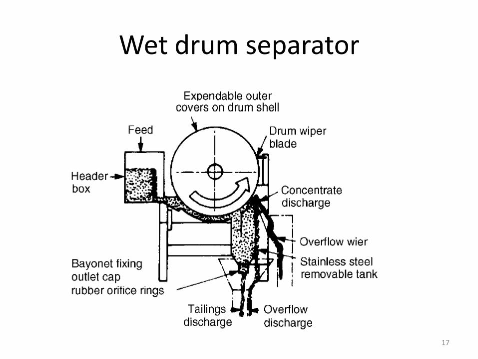
Wet drum separator
17
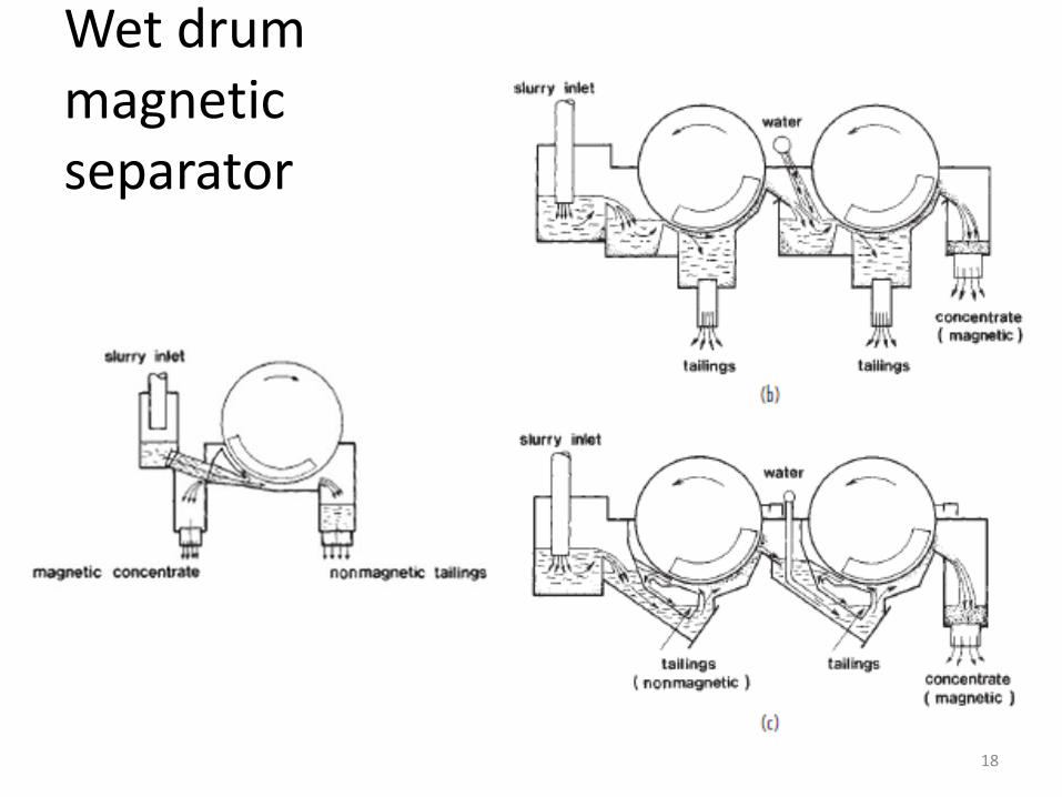
Wet drummagnetic separator
18
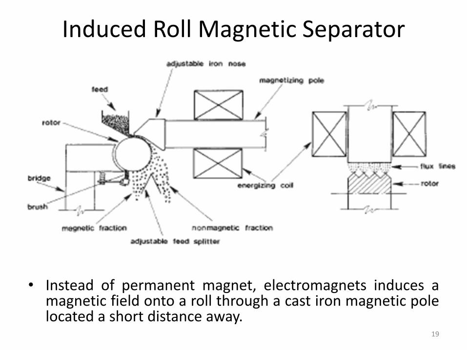
Induced Roll Magnetic Separator
• Instead of permanent magnet, electromagnets induces amagnetic field onto a roll through a cast iron magnetic polelocated a short distance away.
19
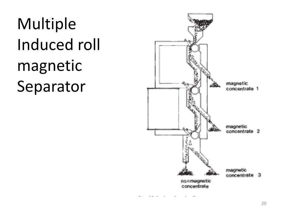
MultipleInduced rollmagneticSeparator
20
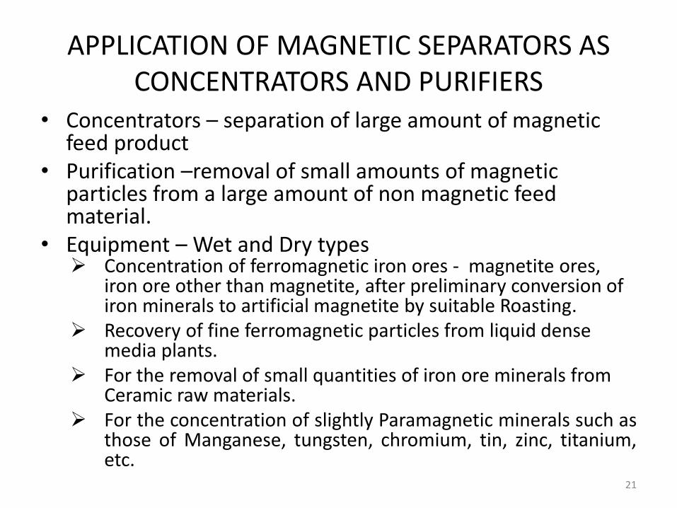
APPLICATION OF MAGNETIC SEPARATORS AS CONCENTRATORS AND PURIFIERS
• Concentrators – separation of large amount of magnetic feed product
• Purification –removal of small amounts of magnetic particles from a large amount of non magnetic feed material.
• Equipment – Wet and Dry types Concentration of ferromagnetic iron ores - magnetite ores,
iron ore other than magnetite, after preliminary conversion of iron minerals to artificial magnetite by suitable Roasting.
Recovery of fine ferromagnetic particles from liquid dense media plants.
For the removal of small quantities of iron ore minerals from Ceramic raw materials.
For the concentration of slightly Paramagnetic minerals such asthose of Manganese, tungsten, chromium, tin, zinc, titanium,etc.
21
ELECTROSTATIC SEPARATORS
22
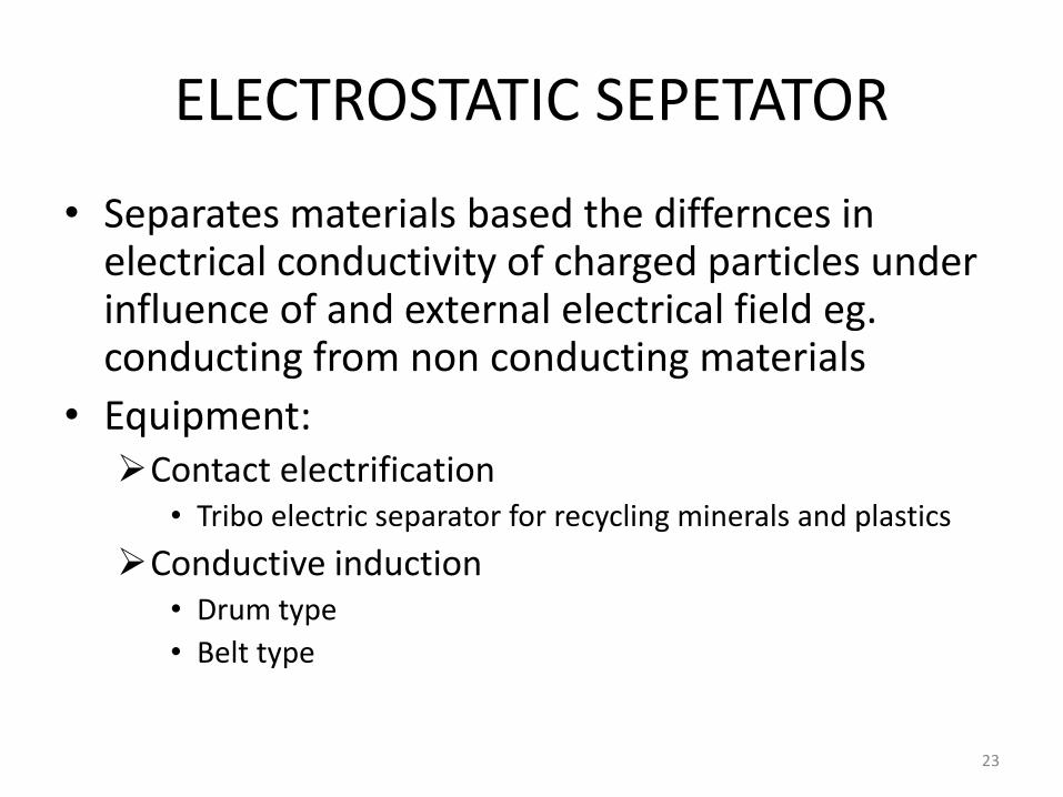
ELECTROSTATIC SEPETATOR
• Separates materials based the differnces in electrical conductivity of charged particles under influence of and external electrical field eg. conducting from non conducting materials
• Equipment:Contact electrification
• Tribo electric separator for recycling minerals and plastics
Conductive induction• Drum type
• Belt type
23
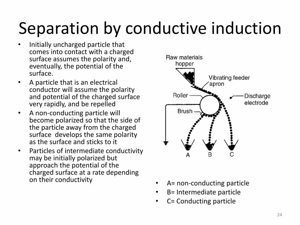
Separation by conductive induction• Initially uncharged particle that
comes into contact with a charged surface assumes the polarity and, eventually, the potential of the surface.
• A particle that is an electrical conductor will assume the polarity and potential of the charged surface very rapidly, and be repelled
• A non-conducting particle will become polarized so that the side of the particle away from the charged surface develops the same polarity as the surface and sticks to it
• Particles of intermediate conductivity may be initially polarized but approach the potential of the charged surface at a rate depending on their conductivity • A= non-conducting particle
• B= Intermediate particle• C= Conducting particle
24
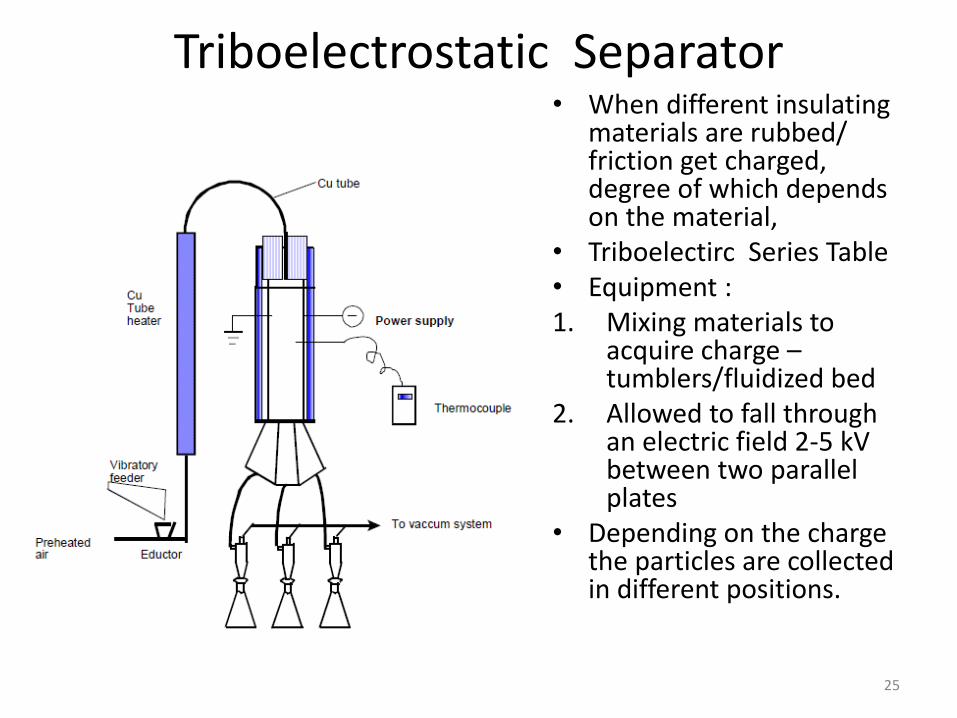
Triboelectrostatic Separator• When different insulating
materials are rubbed/ friction get charged, degree of which depends on the material,
• Triboelectirc Series Table• Equipment : 1. Mixing materials to
acquire charge –tumblers/fluidized bed
2. Allowed to fall through an electric field 2-5 kV between two parallel plates
• Depending on the charge the particles are collected in different positions.
25
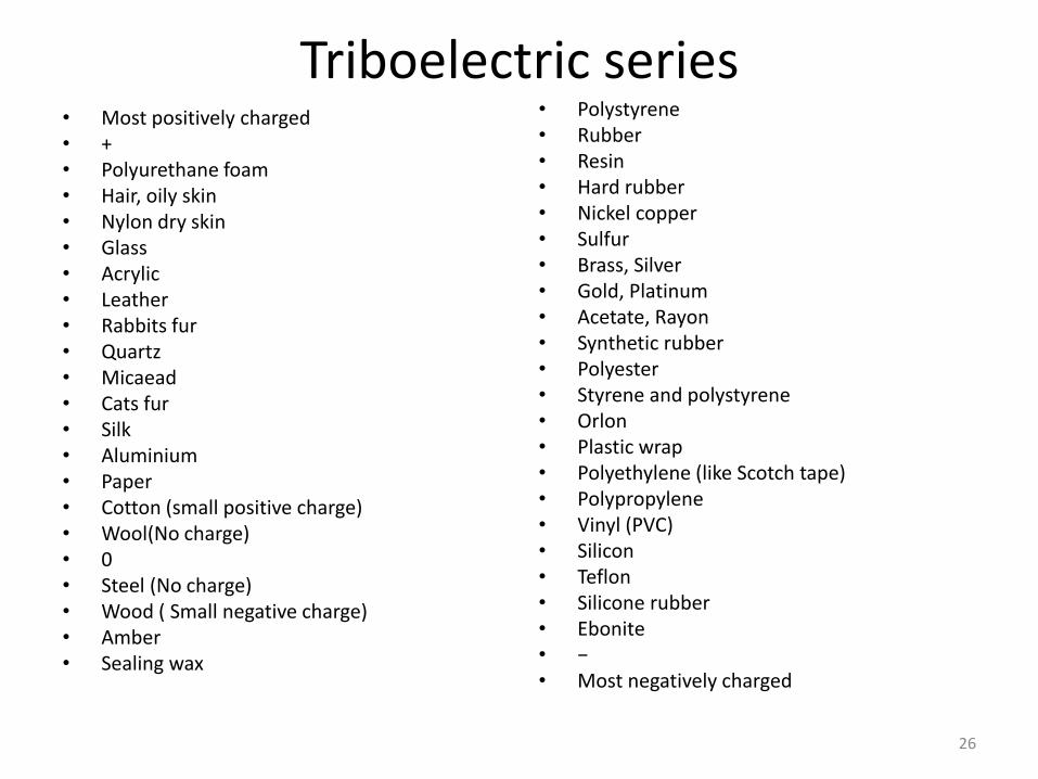
Triboelectric series• Most positively charged• +• Polyurethane foam• Hair, oily skin• Nylon dry skin• Glass• Acrylic• Leather• Rabbits fur• Quartz• Micaead• Cats fur• Silk• Aluminium• Paper• Cotton (small positive charge)• Wool(No charge)• 0• Steel (No charge)• Wood ( Small negative charge)• Amber• Sealing wax
• Polystyrene• Rubber• Resin• Hard rubber• Nickel copper• Sulfur• Brass, Silver• Gold, Platinum• Acetate, Rayon• Synthetic rubber• Polyester• Styrene and polystyrene• Orlon• Plastic wrap• Polyethylene (like Scotch tape)• Polypropylene• Vinyl (PVC)• Silicon• Teflon• Silicone rubber• Ebonite• −• Most negatively charged
26
APPLICATION OF TRIBO-ELECTROSTATIC SEPARATOR• Mineral Beneficiation:
– processing of heavy-mineral beach sands from which are recovered ilmenite, rutile, zircon, monazite, silicates, and quartz.
– High-grade specular hematite concentrates have been recovered at rates of 1000 tons/h in Labrador.
– Processing tin ores to separate cassiterite from columbite and ilmenite.
• Plastic and Metals Recycling – Recover nonferrous metals from industrial plastics (telephone and
communication scrap)– Recycling of beverage bottles to reject any remaining nonferrous metals. – Triboelectric separation involves the separation of PVC from PET and other
plastics. – Permit PVC to assume a strong negative charge and be removed efficiently from
properly protected mixed plastic feedstocks
• Other Applications – differences in surface conductivity and shape factors. – seed sorting, cleaning of spices, – removal of textile from reclaimed plastics, and – separation of paper and plastic.
27
AIR CLASSIFICATION
28
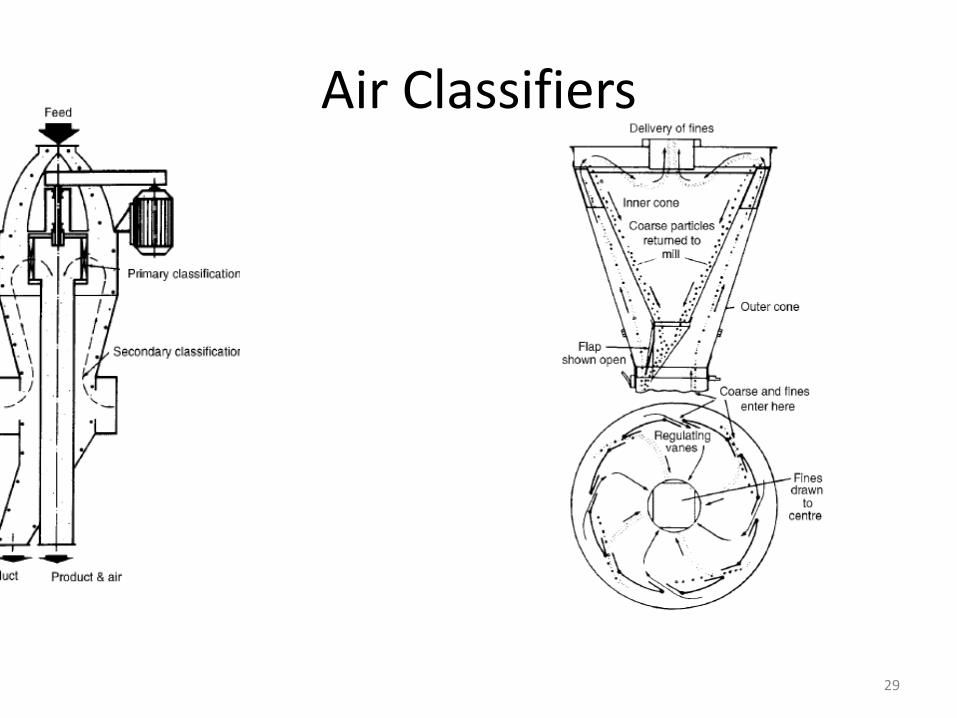
Air Classifiers
29

BALLISTIC SEPARATOR
30
INTERTIAL SEPARATOR
31
WET CLASSIFICATION
32
Hydraulic Classifiers
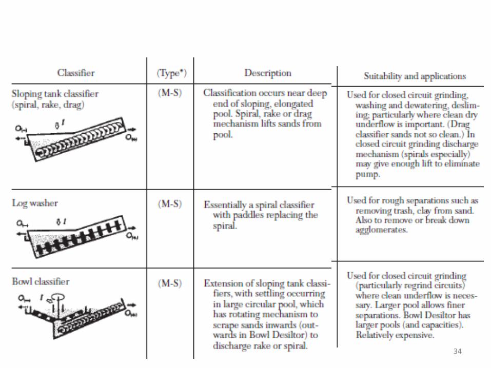
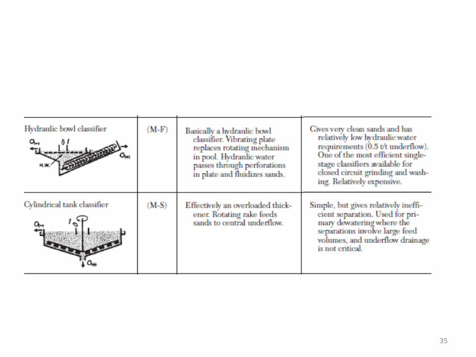
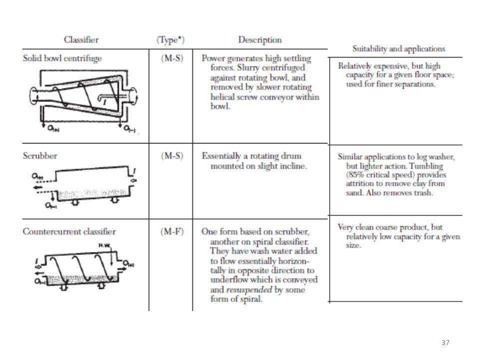
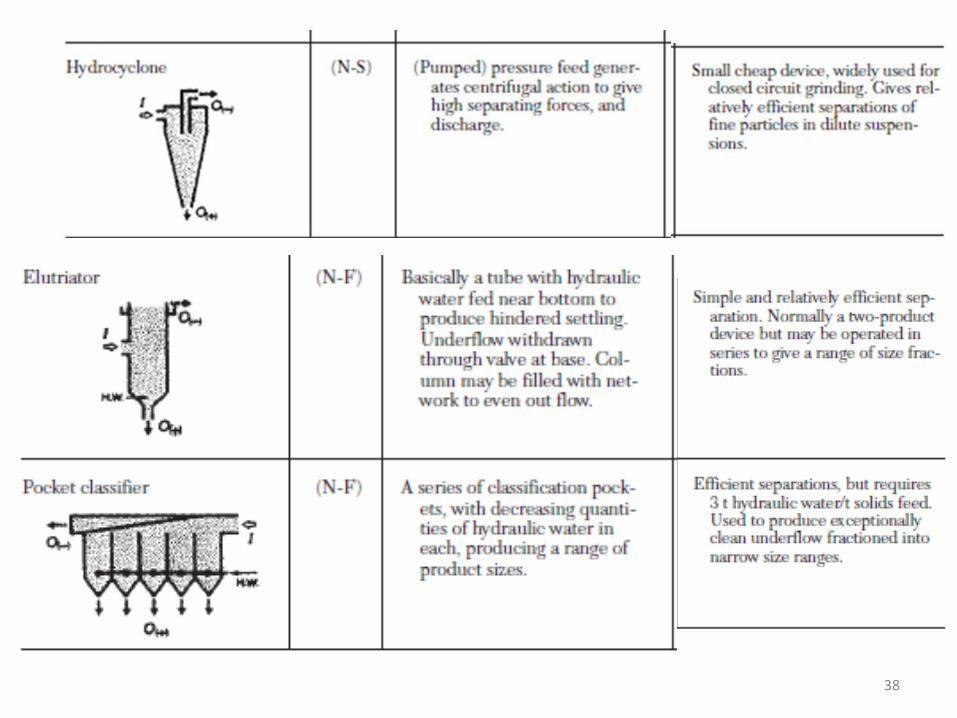
• Mechanical – (M)• Non Mechanical – (N)• Fluidization (F)• Settling (S)• Method of removal of Sand:
• Drag – endless belt or chain to remove sand• Spiral – screw conveyer• Rake – Rakes are used
• Bowl Classifier more pool for fine separation• Hydraulic water for fluidization
33
34
35

36
37
38
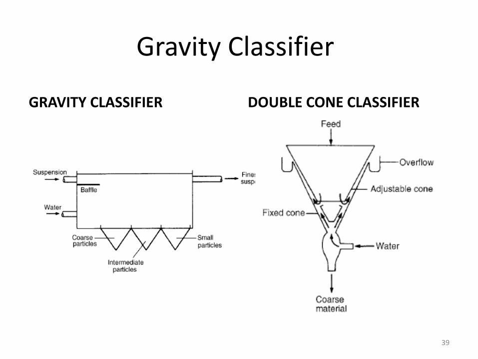
Gravity Classifier
GRAVITY CLASSIFIER DOUBLE CONE CLASSIFIER
39

40
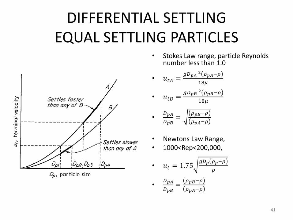
DIFFERENTIAL SETTLINGEQUAL SETTLING PARTICLES
• Stokes Law range, particle Reynolds number less than 1.0
• 𝑢𝑡𝐴 =𝑔𝐷𝑝𝐴
2 𝜌𝑝𝐴−𝜌
18𝜇
• 𝑢𝑡𝐵 =𝑔𝐷𝑝𝐵
2 𝜌𝑝𝐵−𝜌
18𝜇
•𝐷𝑝𝐴
𝐷𝑝𝐵=
𝜌𝑝𝐵−𝜌
𝜌𝑝𝐴−𝜌
• Newtons Law Range,• 1000<Rep<200,000,
• 𝑢𝑡 = 1.75𝑔𝐷𝑝 𝜌𝑝−𝜌
𝜌
•𝐷𝑝𝐴
𝐷𝑝𝐵=
𝜌𝑝𝐵−𝜌
𝜌𝑝𝐴−𝜌
41
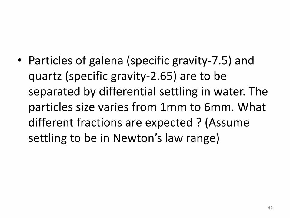
• Particles of galena (specific gravity-7.5) and quartz (specific gravity-2.65) are to be separated by differential settling in water. The particles size varies from 1mm to 6mm. What different fractions are expected ? (Assume settling to be in Newton’s law range)
42
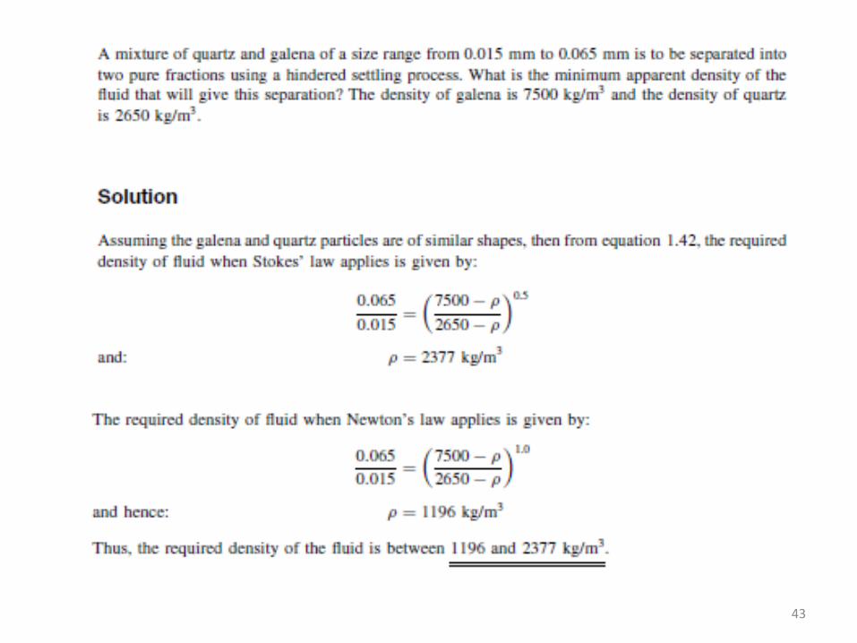
43
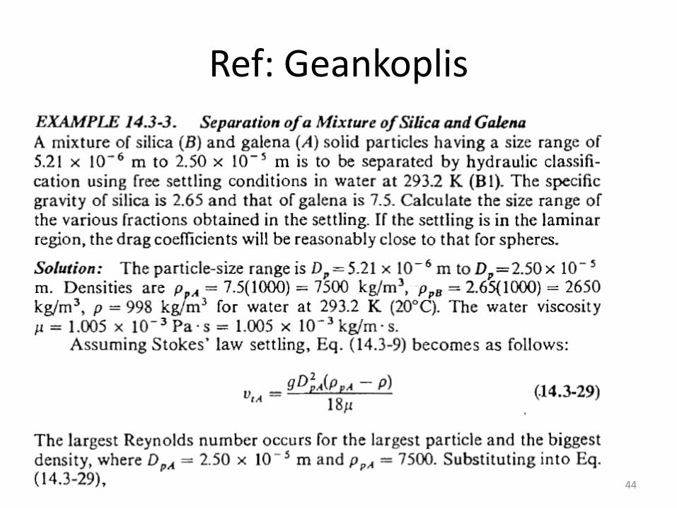
Ref: Geankoplis
44

JIGGING • Principle of differential settling
• 4 fractions
1.Big particles of high density material on the screen, removed from side gate
2. Mixed material on the screen removed from side gate
3. Small particles of high density particles fall through the screen
4. small particles of light material is carried away in the liquid overflow
Types of jigs
Herz
Remer
Baum
Batic45
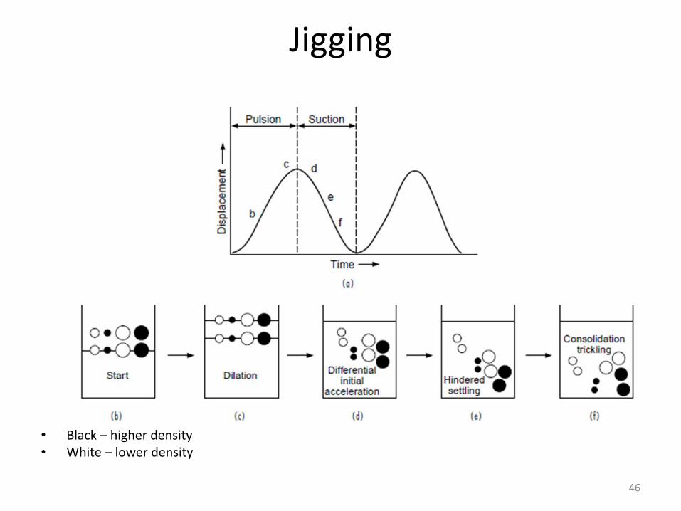
Jigging
• Black – higher density• White – lower density
46
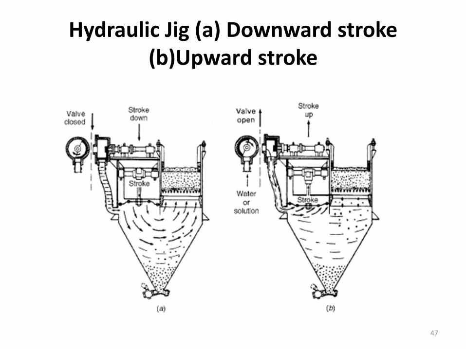
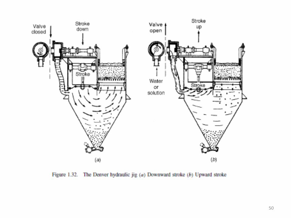
Hydraulic Jig (a) Downward stroke (b)Upward stroke
47
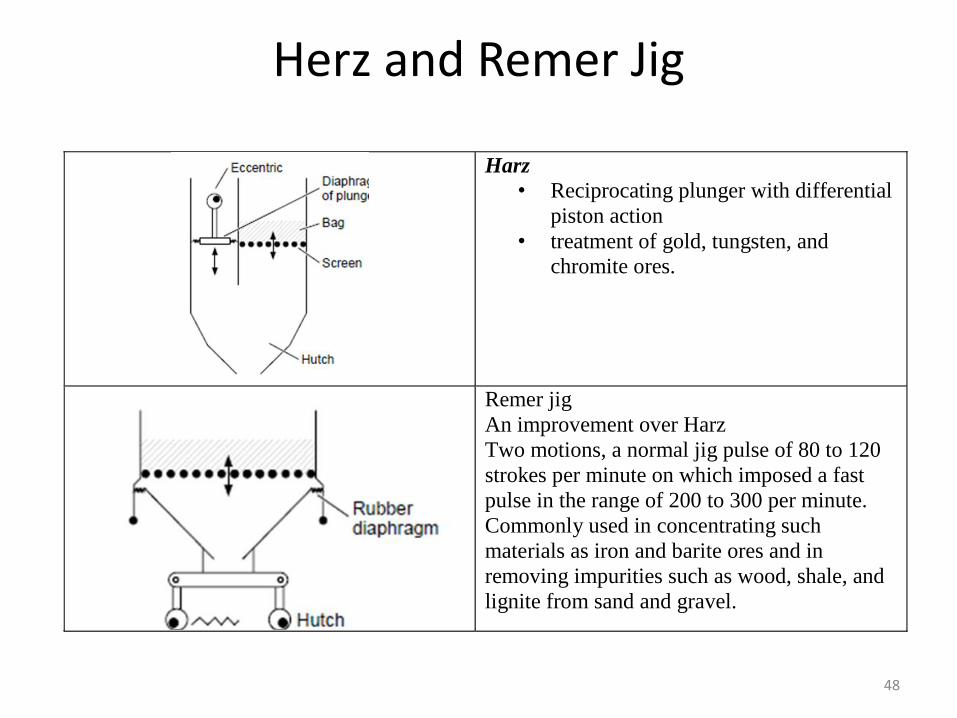
Herz and Remer Jig
Harz
• Reciprocating plunger with differential
piston action
• treatment of gold, tungsten, and
chromite ores.
Remer jig
An improvement over Harz
Two motions, a normal jig pulse of 80 to 120
strokes per minute on which imposed a fast
pulse in the range of 200 to 300 per minute.
Commonly used in concentrating such
materials as iron and barite ores and in
removing impurities such as wood, shale, and
lignite from sand and gravel.
48
Baum Jig, Batac Jig
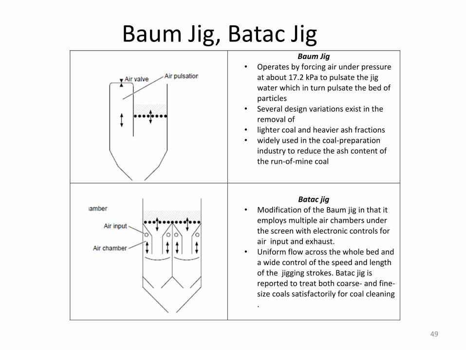
Baum Jig • Operates by forcing air under pressure
at about 17.2 kPa to pulsate the jig water which in turn pulsate the bed of particles
• Several design variations exist in the removal of
• lighter coal and heavier ash fractions • widely used in the coal-preparation
industry to reduce the ash content of the run-of-mine coal
Batac jig
• Modification of the Baum jig in that it employs multiple air chambers under the screen with electronic controls for air input and exhaust.
• Uniform flow across the whole bed and a wide control of the speed and length of the jigging strokes. Batac jig is reported to treat both coarse- and fine-size coals satisfactorily for coal cleaning .
49
50
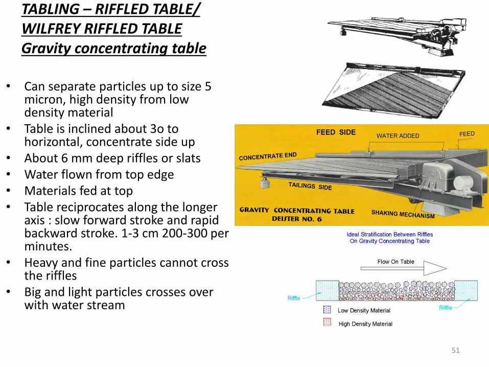
TABLING – RIFFLED TABLE/WILFREY RIFFLED TABLEGravity concentrating table
• Can separate particles up to size 5 micron, high density from low density material
• Table is inclined about 3o to horizontal, concentrate side up
• About 6 mm deep riffles or slats• Water flown from top edge• Materials fed at top• Table reciprocates along the longer
axis : slow forward stroke and rapid backward stroke. 1-3 cm 200-300 per minutes.
• Heavy and fine particles cannot cross the riffles
• Big and light particles crosses over with water stream
51
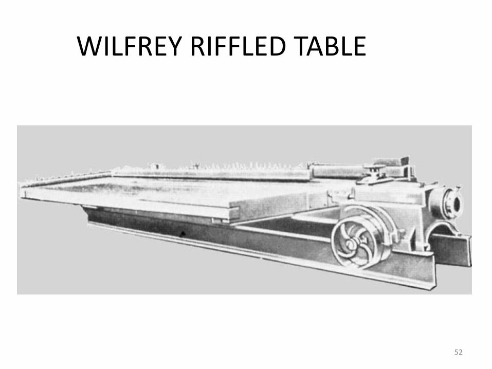
WILFREY RIFFLED TABLE
52
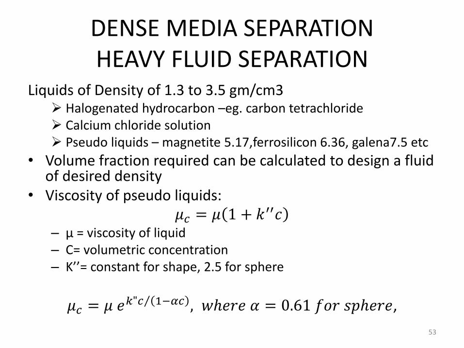
DENSE MEDIA SEPARATIONHEAVY FLUID SEPARATION
Liquids of Density of 1.3 to 3.5 gm/cm3 Halogenated hydrocarbon –eg. carbon tetrachloride Calcium chloride solution Pseudo liquids – magnetite 5.17,ferrosilicon 6.36, galena7.5 etc
• Volume fraction required can be calculated to design a fluid of desired density
• Viscosity of pseudo liquids:𝜇𝑐 = 𝜇 1 + 𝑘′′𝑐
– µ = viscosity of liquid– C= volumetric concentration– K’’= constant for shape, 2.5 for sphere
𝜇𝑐 = 𝜇 𝑒 𝑘"𝑐 1−𝛼𝑐 , 𝑤ℎ𝑒𝑟𝑒 𝛼 = 0.61 𝑓𝑜𝑟 𝑠𝑝ℎ𝑒𝑟𝑒,
53
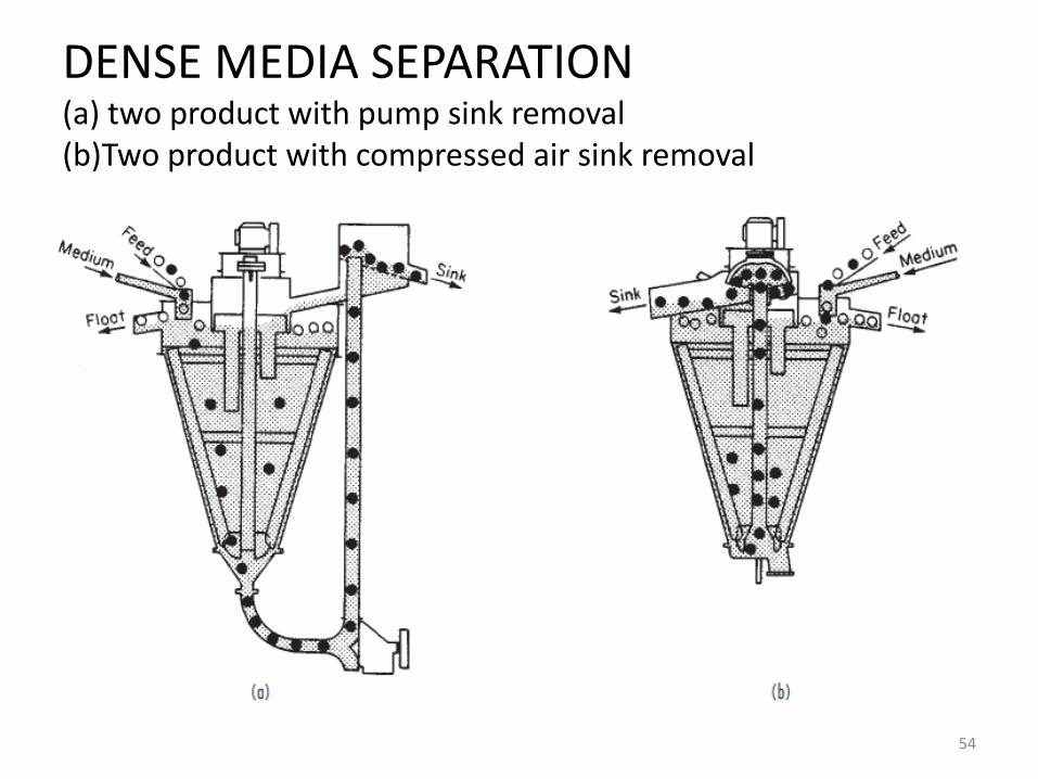
DENSE MEDIA SEPARATION(a) two product with pump sink removal(b)Two product with compressed air sink removal
• hi8i
54

REVOLVING DRUM DENSE MEDIA SEPARATOR
55
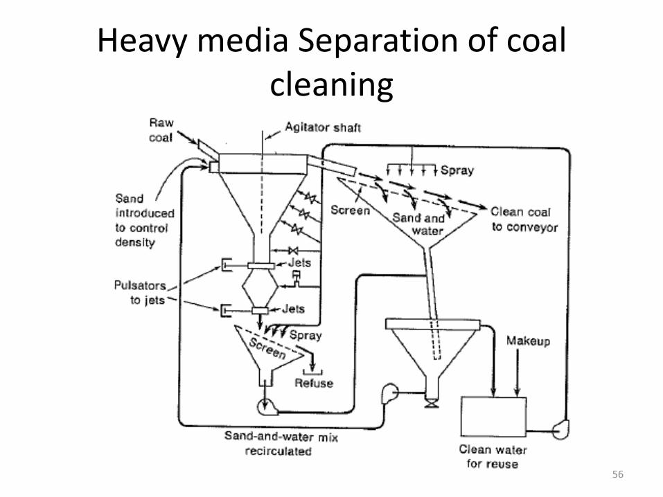
Heavy media Separation of coal cleaning
56
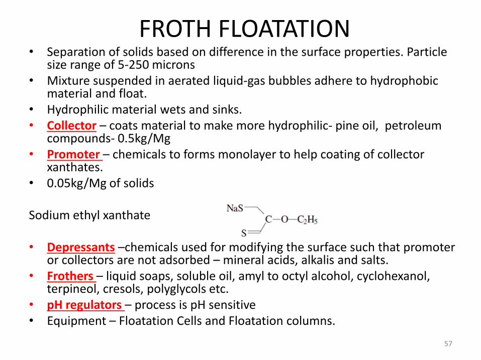
FROTH FLOATATION• Separation of solids based on difference in the surface properties. Particle
size range of 5-250 microns• Mixture suspended in aerated liquid-gas bubbles adhere to hydrophobic
material and float. • Hydrophilic material wets and sinks.• Collector – coats material to make more hydrophilic- pine oil, petroleum
compounds- 0.5kg/Mg• Promoter – chemicals to forms monolayer to help coating of collector
xanthates.• 0.05kg/Mg of solids
Sodium ethyl xanthate
• Depressants –chemicals used for modifying the surface such that promoter or collectors are not adsorbed – mineral acids, alkalis and salts.
• Frothers – liquid soaps, soluble oil, amyl to octyl alcohol, cyclohexanol, terpineol, cresols, polyglycols etc.
• pH regulators – process is pH sensitive• Equipment – Floatation Cells and Floatation columns.
57
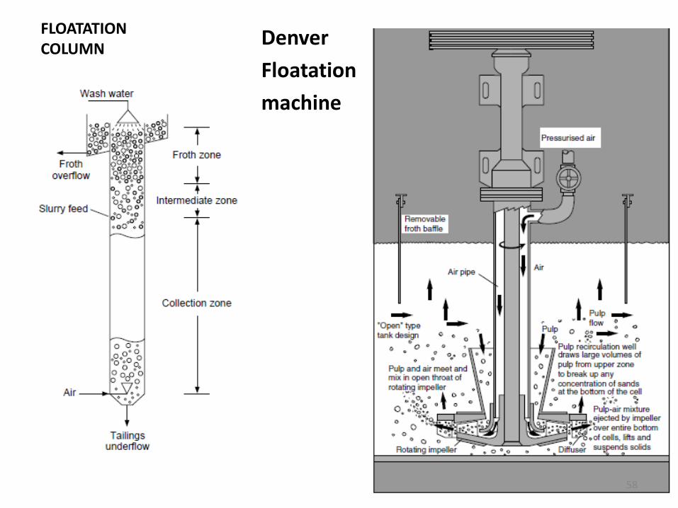
FLOATATIONCOLUMN
Denver
Floatation
machine
58
h OPERATIONS
GAS-SOLID SEPARATION
59

Solid –Gas Separation
Settling
Gravity
Centrifugal-Cyclone
Impingement Separator/filters
Electrostatic Precipitator
Spray Chambers/
Venturi scrubbers
60
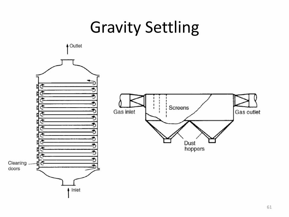
Gravity Settling
61
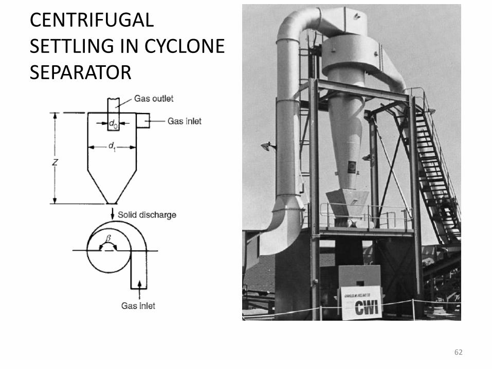
CENTRIFUGALSETTLING IN CYCLONESEPARATOR
62
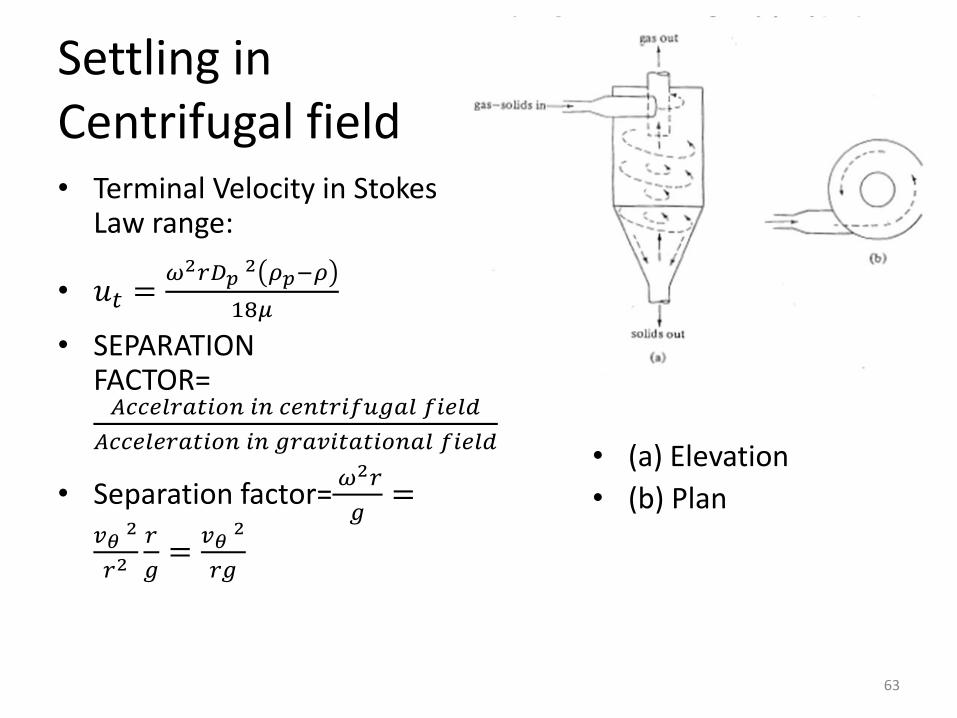
Settling in Centrifugal field• Terminal Velocity in Stokes
Law range:
• 𝑢𝑡 =𝜔2𝑟𝐷𝑝
2 𝜌𝑝−𝜌
18𝜇
• SEPARATION FACTOR=𝐴𝑐𝑐𝑒𝑙𝑟𝑎𝑡𝑖𝑜𝑛 𝑖𝑛 𝑐𝑒𝑛𝑡𝑟𝑖𝑓𝑢𝑔𝑎𝑙 𝑓𝑖𝑒𝑙𝑑
𝐴𝑐𝑐𝑒𝑙𝑒𝑟𝑎𝑡𝑖𝑜𝑛 𝑖𝑛 𝑔𝑟𝑎𝑣𝑖𝑡𝑎𝑡𝑖𝑜𝑛𝑎𝑙 𝑓𝑖𝑒𝑙𝑑
• Separation factor=𝜔2𝑟
𝑔=
𝑣𝜃2
𝑟2𝑟
𝑔=
𝑣𝜃2
𝑟𝑔
63
• (a) Elevation
• (b) Plan
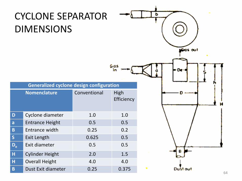
CYCLONE SEPARATORDIMENSIONS
Generalized cyclone design configuration
Nomenclature Conventional High Efficiency
D Cyclone diameter 1.0 1.0
a Entrance Height 0.5 0.5
B Entrance width 0.25 0.2
S Exit Length 0.625 0.5
De Exit diameter 0.5 0.5
H Cylinder Height 2.0 1.5
H Overall Height 4.0 4.0
B Dust Exit diameter 0.25 0.37564
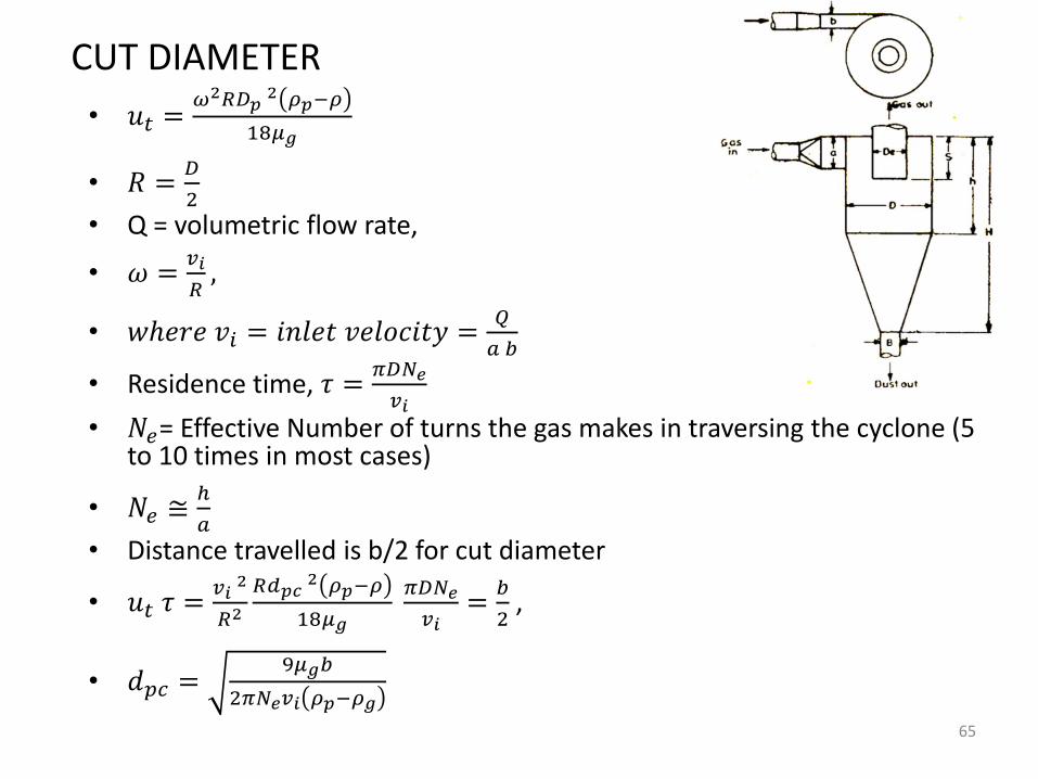
CUT DIAMETER
• 𝑢𝑡 =𝜔2𝑅𝐷𝑝
2 𝜌𝑝−𝜌
18𝜇𝑔
• 𝑅 =𝐷
2
• Q = volumetric flow rate,
• 𝜔 =𝑣𝑖
𝑅,
• 𝑤ℎ𝑒𝑟𝑒 𝑣𝑖 = 𝑖𝑛𝑙𝑒𝑡 𝑣𝑒𝑙𝑜𝑐𝑖𝑡𝑦 =𝑄
𝑎 𝑏
• Residence time, 𝜏 =𝜋𝐷𝑁𝑒
𝑣𝑖• 𝑁𝑒= Effective Number of turns the gas makes in traversing the cyclone (5
to 10 times in most cases)
• 𝑁𝑒 ≅ℎ
𝑎
• Distance travelled is b/2 for cut diameter
• 𝑢𝑡 𝜏 =𝑣𝑖
2
𝑅2
𝑅𝑑𝑝𝑐2 𝜌𝑝−𝜌
18𝜇𝑔
𝜋𝐷𝑁𝑒
𝑣𝑖=
𝑏
2,
• 𝑑𝑝𝑐 =9𝜇𝑔𝑏
2𝜋𝑁𝑒𝑣𝑖 𝜌𝑝−𝜌𝑔
65
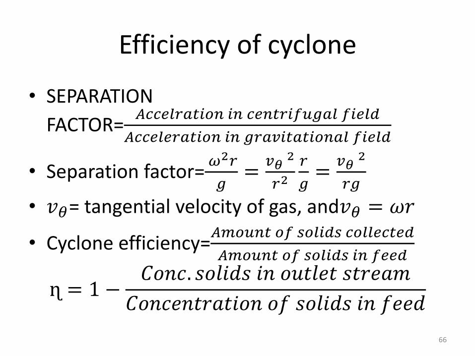
Efficiency of cyclone
• SEPARATION
FACTOR=𝐴𝑐𝑐𝑒𝑙𝑟𝑎𝑡𝑖𝑜𝑛 𝑖𝑛 𝑐𝑒𝑛𝑡𝑟𝑖𝑓𝑢𝑔𝑎𝑙 𝑓𝑖𝑒𝑙𝑑
𝐴𝑐𝑐𝑒𝑙𝑒𝑟𝑎𝑡𝑖𝑜𝑛 𝑖𝑛 𝑔𝑟𝑎𝑣𝑖𝑡𝑎𝑡𝑖𝑜𝑛𝑎𝑙 𝑓𝑖𝑒𝑙𝑑
• Separation factor=𝜔2𝑟
𝑔=
𝑣𝜃2
𝑟2𝑟
𝑔=
𝑣𝜃2
𝑟𝑔
• 𝑣𝜃= tangential velocity of gas, and𝑣𝜃 = 𝜔𝑟
• Cyclone efficiency=𝐴𝑚𝑜𝑢𝑛𝑡 𝑜𝑓 𝑠𝑜𝑙𝑖𝑑𝑠 𝑐𝑜𝑙𝑙𝑒𝑐𝑡𝑒𝑑
𝐴𝑚𝑜𝑢𝑛𝑡 𝑜𝑓 𝑠𝑜𝑙𝑖𝑑𝑠 𝑖𝑛 𝑓𝑒𝑒𝑑
ɳ = 1 −𝐶𝑜𝑛𝑐. 𝑠𝑜𝑙𝑖𝑑𝑠 𝑖𝑛 𝑜𝑢𝑡𝑙𝑒𝑡 𝑠𝑡𝑟𝑒𝑎𝑚
𝐶𝑜𝑛𝑐𝑒𝑛𝑡𝑟𝑎𝑡𝑖𝑜𝑛 𝑜𝑓 𝑠𝑜𝑙𝑖𝑑𝑠 𝑖𝑛 𝑓𝑒𝑒𝑑
66
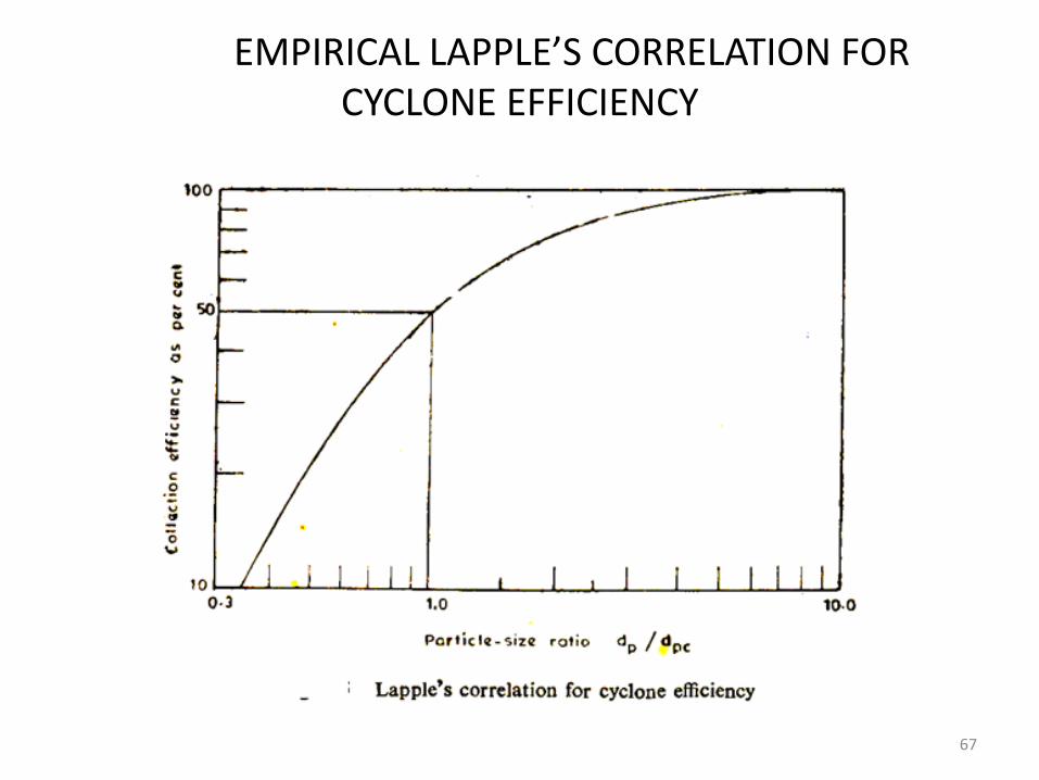
EMPIRICAL LAPPLE’S CORRELATION FOR CYCLONE EFFICIENCY
67
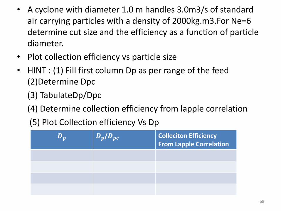
• A cyclone with diameter 1.0 m handles 3.0m3/s of standard air carrying particles with a density of 2000kg.m3.For Ne=6 determine cut size and the efficiency as a function of particle diameter.
• Plot collection efficiency vs particle size
• HINT : (1) Fill first column Dp as per range of the feed (2)Determine Dpc
(3) TabulateDp/Dpc
(4) Determine collection efficiency from lapple correlation
(5) Plot Collection efficiency Vs Dp
68
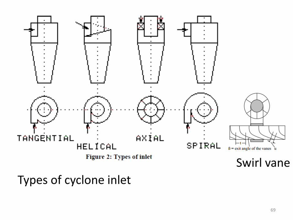
Swirl vane
Types of cyclone inlet
69
70
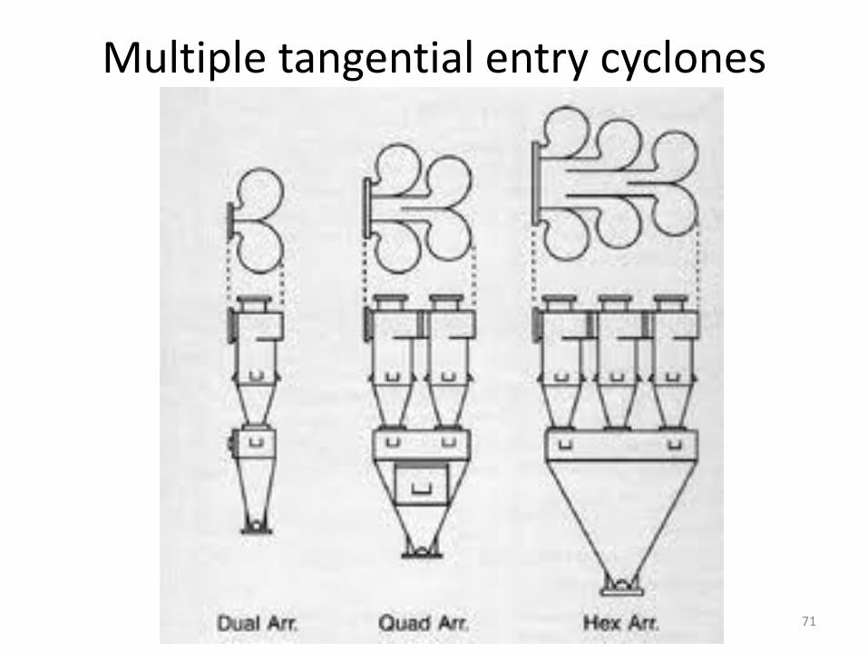
Multiple tangential entry cyclones
71
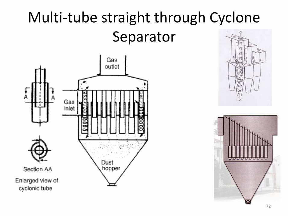
Multi-tube straight through Cyclone Separator
72

INTERTIAL AND MOMENTUM SEPARATORS
73
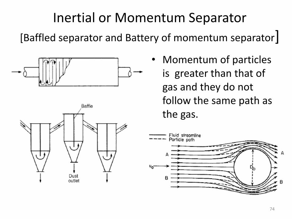
Inertial or Momentum Separator
[Baffled separator and Battery of momentum separator]
• Momentum of particles is greater than that of gas and they do not follow the same path as the gas.
74
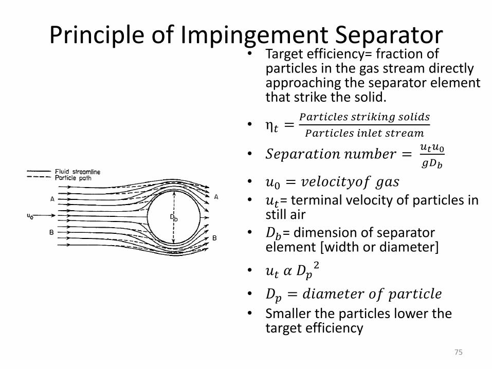
Principle of Impingement Separator• Target efficiency= fraction of
particles in the gas stream directly approaching the separator element that strike the solid.
• η𝑡 =𝑃𝑎𝑟𝑡𝑖𝑐𝑙𝑒𝑠 𝑠𝑡𝑟𝑖𝑘𝑖𝑛𝑔 𝑠𝑜𝑙𝑖𝑑𝑠
𝑃𝑎𝑟𝑡𝑖𝑐𝑙𝑒𝑠 𝑖𝑛𝑙𝑒𝑡 𝑠𝑡𝑟𝑒𝑎𝑚
• 𝑆𝑒𝑝𝑎𝑟𝑎𝑡𝑖𝑜𝑛 𝑛𝑢𝑚𝑏𝑒𝑟 =𝑢𝑡𝑢0
𝑔𝐷𝑏
• 𝑢0 = 𝑣𝑒𝑙𝑜𝑐𝑖𝑡𝑦𝑜𝑓 𝑔𝑎𝑠• 𝑢𝑡= terminal velocity of particles in
still air• 𝐷𝑏= dimension of separator
element [width or diameter]
• 𝑢𝑡 𝛼 𝐷𝑝2
• 𝐷𝑝 = 𝑑𝑖𝑎𝑚𝑒𝑡𝑒𝑟 𝑜𝑓 𝑝𝑎𝑟𝑡𝑖𝑐𝑙𝑒
• Smaller the particles lower the target efficiency
75
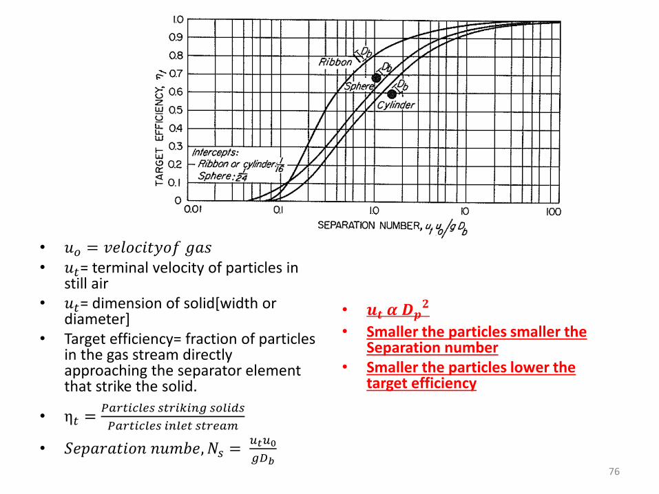
• 𝑢𝑜 = 𝑣𝑒𝑙𝑜𝑐𝑖𝑡𝑦𝑜𝑓 𝑔𝑎𝑠• 𝑢𝑡= terminal velocity of particles in
still air• 𝑢𝑡= dimension of solid[width or
diameter]• Target efficiency= fraction of particles
in the gas stream directly approaching the separator element that strike the solid.
• η𝑡 =𝑃𝑎𝑟𝑡𝑖𝑐𝑙𝑒𝑠 𝑠𝑡𝑟𝑖𝑘𝑖𝑛𝑔 𝑠𝑜𝑙𝑖𝑑𝑠
𝑃𝑎𝑟𝑡𝑖𝑐𝑙𝑒𝑠 𝑖𝑛𝑙𝑒𝑡 𝑠𝑡𝑟𝑒𝑎𝑚
• 𝑆𝑒𝑝𝑎𝑟𝑎𝑡𝑖𝑜𝑛 𝑛𝑢𝑚𝑏𝑒, 𝑁𝑠 =𝑢𝑡𝑢0
𝑔𝐷𝑏
• 𝒖𝒕 𝜶 𝑫𝒑𝟐
• Smaller the particles smaller the Separation number
• Smaller the particles lower the target efficiency
76
FILTERS FOR GAS SOLID SEPARATION
77
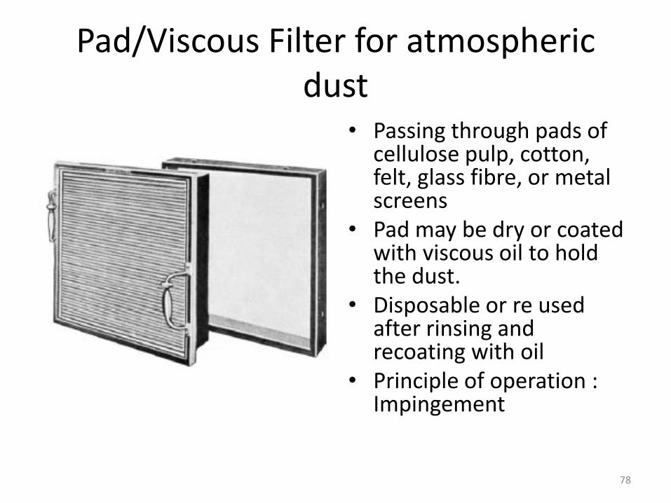
Pad/Viscous Filter for atmospheric dust
• Passing through pads of cellulose pulp, cotton, felt, glass fibre, or metal screens
• Pad may be dry or coated with viscous oil to hold the dust.
• Disposable or re used after rinsing and recoating with oil
• Principle of operation : Impingement
78

Process dust removal
• Granular Bed filter
• Bag filters
79
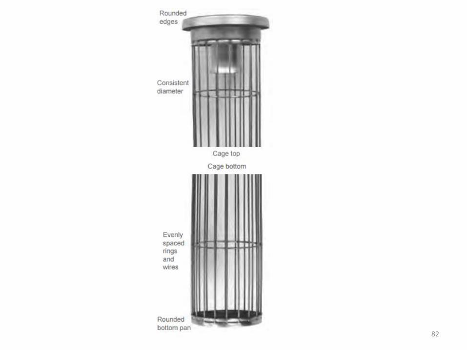
FABRIC FILTERS
• Felt or woven fabric bag• Cotton, PVC, PP, Nylon,
PPS, Polyester, aramid, polyimide, PTFE, fibreglass
• Fibres of 500 micron, spaced 100 to 200 micron apart. Individual fibre are 5-10 micron. Due to criscross even 1 micron particles are removes.
• Efficiency increases when loose flocs are formed.
• Velocity 0.005 to 0.03m/s • Types of bag house filter:
1. Simple Bag house filter max velocity 0.03 m/s
2. Automatic Bag house filter- Heavier fabric velocity 0.02m/, with shaking facilities-mechanical, vibratory, air pulse
3. Reverse jet filter velocity 0.05m/s
80
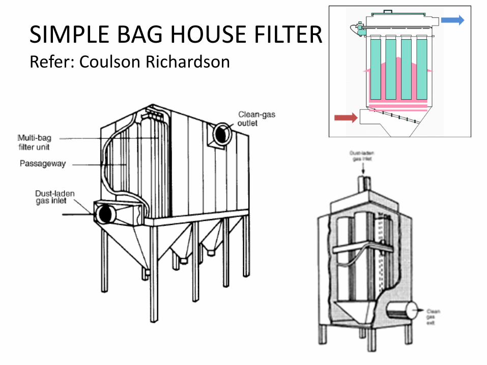
SIMPLE BAG HOUSE FILTERRefer: Coulson Richardson
81
82
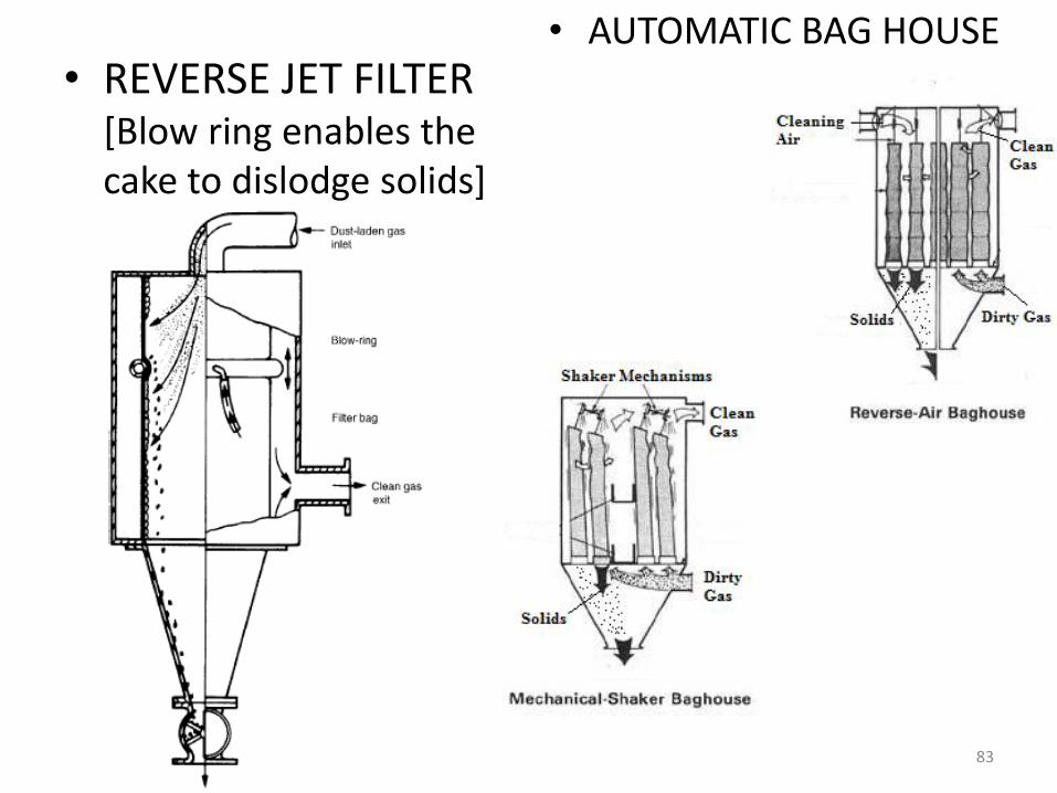
• REVERSE JET FILTER[Blow ring enables the cake to dislodge solids]
• AUTOMATIC BAG HOUSE
83
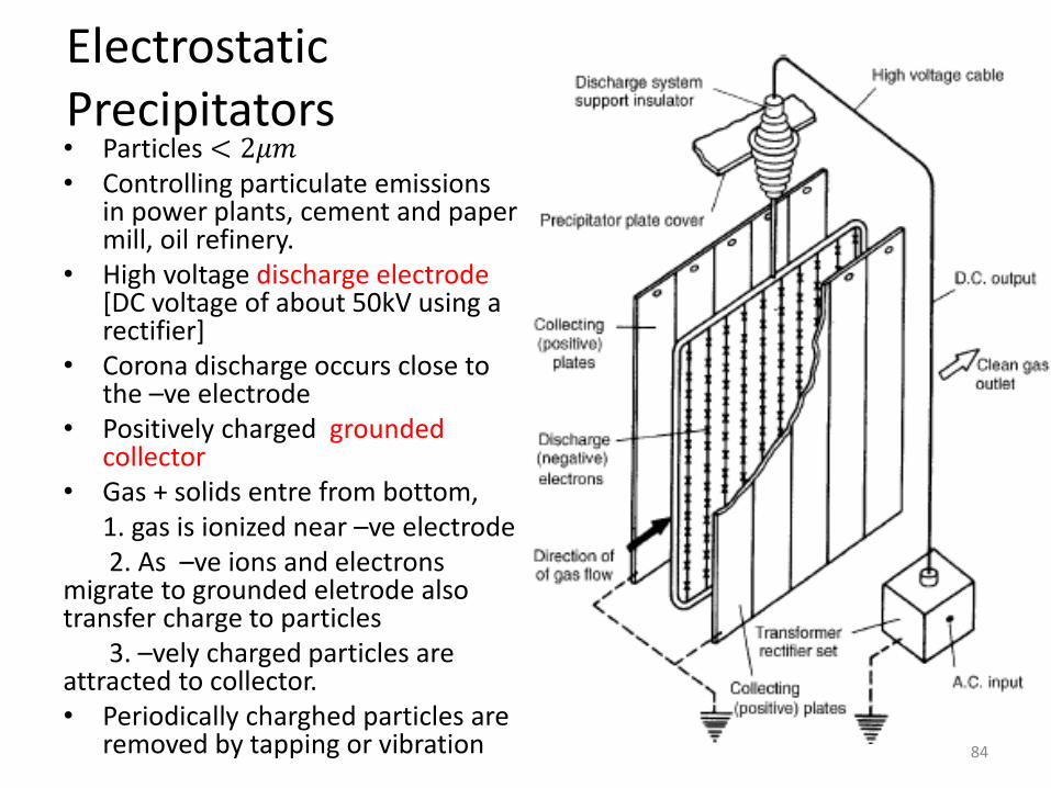
ElectrostaticPrecipitators• Particles < 2𝜇𝑚• Controlling particulate emissions
in power plants, cement and paper mill, oil refinery.
• High voltage discharge electrode [DC voltage of about 50kV using a rectifier]
• Corona discharge occurs close to the –ve electrode
• Positively charged grounded collector
• Gas + solids entre from bottom, 1. gas is ionized near –ve electrode2. As –ve ions and electrons
migrate to grounded eletrode also transfer charge to particles
3. –vely charged particles are attracted to collector.• Periodically charghed particles are
removed by tapping or vibration 84
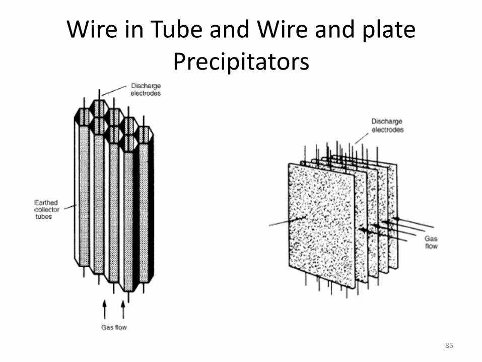
Wire in Tube and Wire and plate Precipitators
85

SCRUBBING - WET METHOD OF GAS SOLID REMOVAL
SPRAY CHAMBERS
VENTURI SCRUBBERS
86
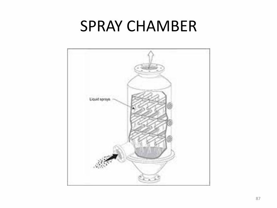
SPRAY CHAMBER
87
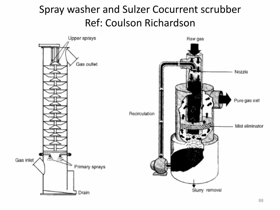
Spray washer and Sulzer Cocurrent scrubberRef: Coulson Richardson
88
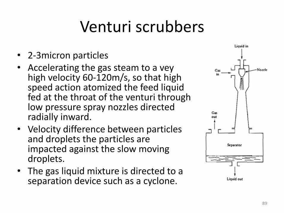
Venturi scrubbers
• 2-3micron particles• Accelerating the gas steam to a vey
high velocity 60-120m/s, so that high speed action atomized the feed liquid fed at the throat of the venturi through low pressure spray nozzles directed radially inward.
• Velocity difference between particles and droplets the particles are impacted against the slow moving droplets.
• The gas liquid mixture is directed to a separation device such as a cyclone.
89
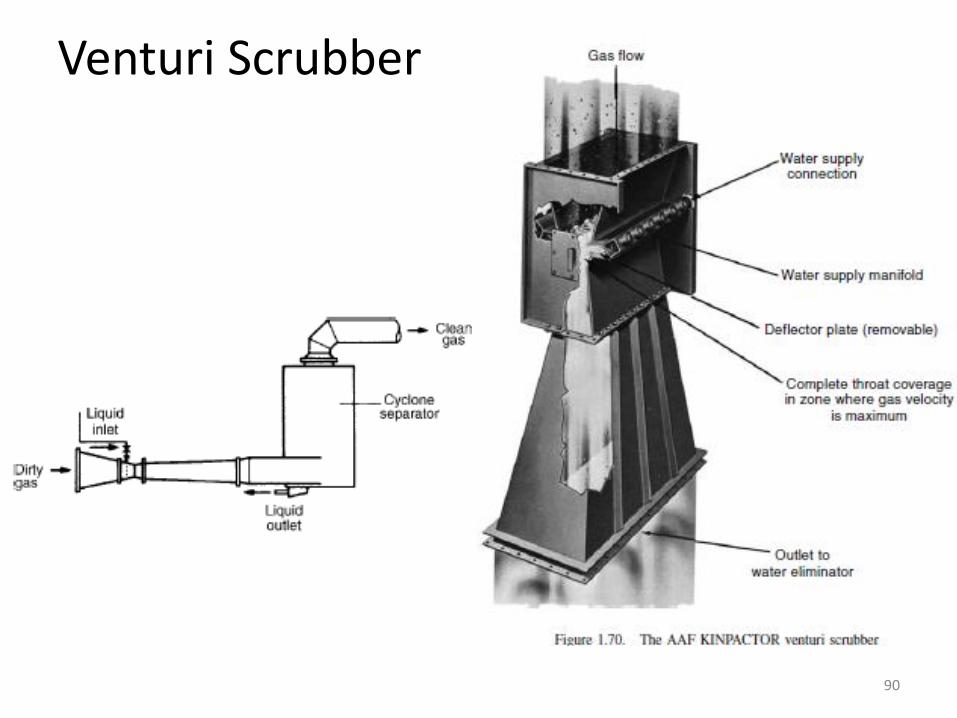
Venturi Scrubber
90