oil flow control upgraded vacuum carburizing … vol. 49 no. 1 2016 oil flow control upgraded vacuum...
TRANSCRIPT
18 Vo l . 4 9 N o . 1 2 016
Oil Flow Control Upgraded Vacuum Carburizing ProcessQuality variations in vacuum carburizing products were reduced by making the oil flow uniformVacuum carburizing is a process in which a material surface is hardened by quenching after carbon has been diffused over a work surface under high temperature and low pressure. The coolant (oil) flow distribution was optimized in this quenching process. This enables variations in the distortion and hardness of the treated material to be reduced and contributes to improving productivity.
SAKAMOTO OsamuTechnology Department, Vacuum & Advanced Material Furnace Division,IHI Machinery and Furnace Co., Ltd.
IHI Machinery and Furnace Co., Ltd.
Heat treatment in a vacuumHeat treatment is one of the methods used to change the properties of metals that is widely used for many applications, such as automobile parts, construction machinery, machine tools, and aircraft parts.
Until recently, heat treatment was carried out in a gas atmosphere, but it is now carried out in a vacuum to reduce the burden on the environment. Vacuum heat treatment does not discharge carbon dioxide (CO2) and loses little heat from
the heater due to vacuum insulation. Because of these characteristics, vacuum heat treatment has been evaluated as environmentally friendly and energy saving, and the vacuum heat treatment has replaced the gas atmosphere treatment.
Particularly because the vacuum carburizing process can harden the surface of a material using relatively inexpensive metals as well as improve wear resistance, demand for vacuum carburizing is increasing in many industrial fields, both domestically and globally.
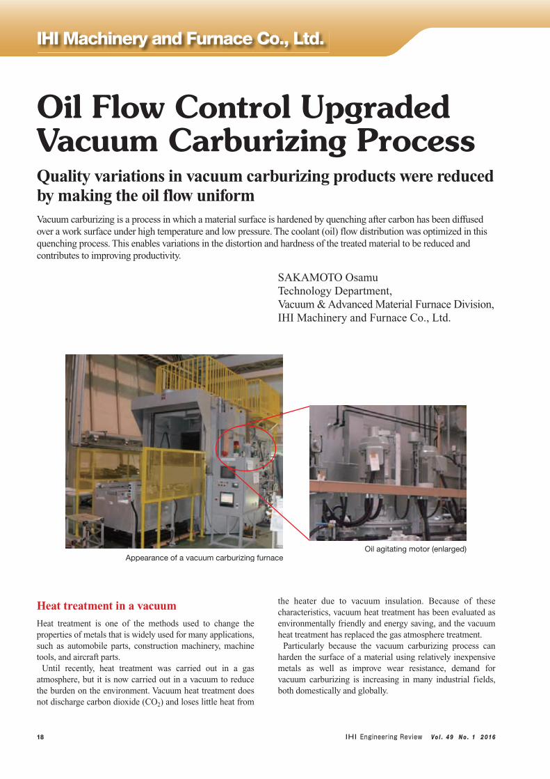
Appearance of a vacuum carburizing furnaceOil agitating motor (enlarged)

19Vo l . 4 9 N o . 1 2 016
Technologies
Quality of vacuum-carburizing productsThere are various types of heat treatments. This section describes the vacuum carburizing process, one of these heat treatment processes.
Vacuum carburizing is a heat treatment process that diffuses carbon on a steel surface under low pressure. Immediately after this process, the steel is quenched with coolant to improve its wear resistance by hardening the surface. Since a relatively inexpensive material can be used to improve the wear resistance, this process is applied to mass-produced products, such as automobile gears.
The following three points are required to ensure the quality of the process:① The effective carburizing depth is uniform.② The surface hardness satisfies the specification.③ The distortion satisfies the specification.
Requirement ① can be satisfied by minimizing temperature variation among workpieces. To satisfy requirements ② and ③, it is important to choose the best coolant and optimize the coolant flow distribution over the workpiece, as surface hardness and distortion depend considerably on the material, the workpiece shapes, and the workpiece positioning, as well as the coolant materials and the contact condition between the coolant and the workpieces.
Coolant fluid (Water/Gas/Oil)The coolant fluid for quenching can be categorized into three types: water, gas and oil.
Among these, water is the most effective in removing heat from a workpiece. However, the quenching speed is so fast that non-uniform cooling often occurs and cracks on hardened materials are often observed.
Gas is the least effective of the three coolants. Nitrogen gas is mainly used because of its low cost and relatively high safety. Gas quenching under a normal atmospheric pressure does not work well, resulting in the quality requirements not being satisfied. Satisfactory quenching requires a high pressure of around 10 to 20 atm. However, to satisfy the quality requirements, gas quenching requires many conditions to be
satisfied, such as preparing high-pressure containers and selecting materials suited to quenching.
Finally, the cooling ability of oil is between that of water and gas. By using oil, it is relatively easy to solve problems such as quenching cracks and uneven and/or unsatisfactory hardness. By controlling oil temperature, this process is applicable to a wide variety of workpiece types. High-temperature oil quenching enables distortion to be reduced, and relatively low-temperature quenching makes it possible to attain the required workpiece hardness, which is difficult to achieve by conventional quenching. Oil allows relatively easy control contributing to stable quality of carburized products. Oil is the coolant fluid that is most commonly used in Japan for vacuum carburizing. IHI Machinery and Furnace Co., Ltd. (IMS) supplies an oil quenching system as the standard vacuum carburization furnace.
Influence of coolant (oil) flow distribution on qualityAlthough using oil as a coolant has the advantages described above, oil quenching does not always ensure the required quality. The hardness after quenching varies according to the area in question even in the same lot, depending on the material, the mass, the shape, the number of workpieces, and the direction and stacking conditions of the workpieces when quenching. Ensuring that the distortion and hardness of each workpiece satisfies the standard specified for the part is essential to maintaining product quality. Even when the oil flow rate is increased to ensure good hardenability, if the flow over the workpieces is not uniform, variations in hardness and distortion increase, resulting in process failures.
Therefore, in the oil quenching process, it is important to rectify the oil flow from the agitator and to obtain uniform contact between the oil flow and the workpieces.
Improving oil flow distributionWhen we used a conventional agitation device, variations in the distortion and hardness did not allow for the required quality. The first measure to solve these problems using the conventional agitator was to decrease the number of
Duct inside the oil tank Loaded products after treatment

20 Vo l . 4 9 N o . 1 2 016
workpieces in each lot and to improve the coolant flow. This measure helped to obtain the required hardness. Next, the flow rate distribution was examined with the aim of reducing variations in distortion, and we decided not to place workpieces within low flow rate areas. As a result, variations in hardness and distortion satisfied the required quality. This ensured quality, but the unit production cost increased due to the decreased number of parts per lot. For this reason, we aimed to improve the oil agitation ability to satisfy the quality requirements while keeping the original number of productions of each lot.
Optimization of the flow-rectifying duct was studied in light of the case of partial modification of the existing equipment.
Problems in the existing oil-agitator ductThe problem with the existing oil-agitator duct was that the deviation in oil flow depended on the rotational direction of the agitator. Until now, this process has mainly treated automobile gear parts, because the material and shape used for these parts meant that they were easy to harden and there was no need to make the cooling oil flow uniform. In other words, as quality requirements were satisfied, no consideration was given to uniformity improvement in the oil flow.
The workpiece treated here is a shaft part that is made of a material that is difficult to harden sufficiently. Since these shafts are packed upright, the oil flow is affected by them. Thus, measures were needed to make contact between the oil and the shafts uniform and increase the overall flow rate around areas where the oil was not sufficiently distributed.
Study of a new duct configurationFluid flow simulations were performed to optimize the duct configuration.
The oil flow in the existing oil-agitator duct was poorly distributed. To resolve this problem, we examined a structure with constant cross sectional areas that do not decrease from the propeller-housing cylinder to the duct exit. For this examination, a 3-D model from the cylinder to the exit was
designed, the oil flow section was subdivided into small sections, and each cross-sectional area was measured and modified. Modifications of the model were repeated until a structure without decreasing sectional areas was obtained. Finally, a duct model with cross sectional areas that do not decrease from the inlet to the exit was successfully obtained.
A flow analysis was performed for this duct structure. As a result, high and low flow rate areas were observed. The flow rate distribution of each exit section was also obtained. At
IHI Machinery and Furnace Co., Ltd.
Duct with a cross sectional area that does not decrease from the inlet port to the exit
(with no vertical direction plates)
Oil exit
Direction ofoil flow
Flow analysis results for the duct with no vertical direction plates, and average flow rate distribution at the exit port
High flow rate areaLow flow rate area
Average : 10.9
25
15
10
5
011 12 13 14 21 22 23 24
Location No.
Flo
w r
ate
(kg
/s) 20
Oil flow from the existing oil-agitating duct
Oil flow deviation produced a partialprotrusion on the deviated side

21Vo l . 4 9 N o . 1 2 016
Technologies
this stage, although the flow rate distribution was more uniform than before, there was still a little non-uniformity. The difference between low and high flow rates needed to be considered.
Next, in order to divide the flow from the propeller-housing cylinder at the duct inlet, a different structure that had vertical plates in the duct was designed.
An analysis was performed on this structure, and the flow rates at the subdivided exit became relatively uniform with a
few exceptions.The duct with vertical plates supported by good analytical
results was manufactured. It was installed in an actual furnace for verification. As a result, it achieved a uniform oil flow without the local oil distributions observed in the existing duct.
Future developmentCareful examination of consistency between these analytical results and the quality of products treated in an actual furnace is now underway. After the practical test proves to be consistent with the analytical results, the design concept for this duct structure will be applied in the IMS standard vacuum carburizing furnace. By improving the basic performance of the standard furnace, we aim to develop a new type of furnace that can be used for a wider variety of treatments.
Inquiries:Technology Department, Vacuum & Advanced Material Furnace Division,IHI Machinery and Furnace Co., Ltd.Phone: +81-58-379-1306Website: www.ihi.co.jp/ims/
Duct with vertical direction plates
Vertical direction plate
Average : 12.4
25
15
10
5
011 12 13 14 21 22 23 24
Location No.
Flo
w r
ate
(kg
/s) 20
Flow analysis results for the duct with vertical direction plates, and average flow rate distribution at the exit
The bump area has become nearly flat
Oil flow in the new oil-agitator duct