of sol-gel dip-coating - university of new mexicosolgel/publicationspdf/1994/brinker... · of...
TRANSCRIPT

J. Phys. Ill Fiance 4 (1994) 1231-1242 JULY 1994, PAGE 1231
Classification
Physic-s Absn.act.I
8 15
Fundamentals of sol-gel dip-coating
C. Jeffrey Brinker and Alan J. Hurd
Sandia National Laboratories, Advanced Materials Laboratory, 1001 University Blvd. SE ;
Suite100, Albuquerque, NM 87106, U-S-A-
(Received 23 November 1993, revised14 Marc-h 1994, accepted 29 Maich 1994)
Rdsumk. Pendant l'opdration de«
dip-coating », le substrat est retir6 du sol h vitesse constante.
La couche s'amincit du fait de l'dvaporation du solvant et de l'6coulement gravitationnel. Aprdsplusieurs secondes, le processus atteint un rdgime stationnaire. Le profil du film ddposd reste alors
constant par rapport h la surface du sol. On peut le caractdri~er in situ par des mdthodes optiquestelles que l'ellipsomdtrie et la spectroscopie de fluorescence. La texture et les propridt6s de la
couche ddpendent de la taille et de la structure (par exemple de la dimension fractale) des espbces
en solution, de l'importance de la tension capillaire pendant le sdchage, et des cin6tiques de
condensation. En contrblant ces parambtres, on peut faire varier la porositd de la couche dans une
large gamme.
Abstract. During the process of diprcoating, the substrate is withdrawn from the sol at a
constant rate. After several seconds, the process becomes steady. The entrained film thins byevaporation of solvent and gravitational draining. Because the shape of the depositing film remains
constant with respect to the reservoir surface, it is possible to use analytical methods such as
ellipsometry and fluorescence spectroscopy to characterize the depositing film in situ. The
micro~tructure and properties of the film depend on the size and structure of the inorganic ml
species, the magnitude of the capillary pressure exerted during drying. and the relative rates of
condensation and drying. By controlling these parameters, it is possible to vary the porosity of the
film over a wide range.
Introduction,
Thin films formed by a dip-coating process represent the oldest commercial application of sol-
gel technology. The first patent based on this process was issued to Jenaer Glaswerk Schott &
Gen. in 1939 for silica films II ]. Today sol-gel coatings are being studied for a diverse rangeof applications including protective coatings, passivation layers, ferroelectrics, sensors and
membranes [2]. Despite significant advances in technologies based on sol-gel thin-film
processing, there has been relatively little effort directed toward understanding the fundamen-
1232 JOURNAL DE PHYSIQUE III N° 7
tats of the coating process itself. It is, however, the coating process that serves as the link
between the structure of the solution or sol and the microstructure of the deposited film. This
paper reviews recent work that addresses the underlying physics and chemistry of sol-gel thin
film formation by dip-coating. We first review briefly the aspects of sol-gel chemistry that
govern the size and structure of the inorganic species, which along with the solvent(s)comprise the coating sol. We then discuss the salient features of dip-coating based on various
means of in situ characterization of the film deposition process. Finally, we address the
deposition of inorganic sols with regard to time scales and the effects of sol structure and
capillary pressure on such properties as refractive index, surface area, and pore size of the
deposited film.
Sol-gel chemistry,
The sol-gel process uses inorganic or metal-organic precursors [2]. In aqueous or organicsolvents, the precursors are hydrolyzed and condensed to form inorganic polymers composed
of M-O-M bonds. For inorganic precursors (salts), hydrolysis proceeds by the removal of a
proton from an aquo ion to form a hydroxo (-OH) or oxo (=O) ligand. Condensation reactions
involving hydroxo ligands result in the formation of bridging hydroxyl (M-p(OH)-M) or oxo
(M-O-M) bonds. Normally, monomeric aqueous ions are the only stable species at low pH and
various monomeric or oligomeric anions the only species observed at high pH. At intermediate
pH, well-defined polynuclear ions are often the stable solution species, but the metal solubilityis normally limited there and, when exceeded, results in the precipitation of oxyhydroxides or
oxides [3].The most commonly used metal-organic precursors are metal alkoxides, M (OR ),, where R is
an alkyl group. Normally the alkoxide is dissolved in its parent alcohol and hydrolyzed by the
addition of water plus, in the case of more electronegative metals or metalloids, acid or base
catalyst. Hydrolysis replaces alkoxide Ii gands with hydroxyl ligands. Subsequent condensation
reactions involving the hydroxyl ligands produce oligomers or polymers composed of M-O-M
or M-p(OH)-M bonds.
For both inorganic and metal-organic precursors, the structure of the evolving oligomers or
polymers depends on the extent of hydrolysis and the preferred coordination number or
functionality of the metal [2, 4]. In the case of inorganic precursors, the extent of hydrolysis is
generally controlled by the pH, while the effective functionality may be controlled (reduced)through complexation with mono- or multidentate anionic species. The extent of hydrolysis of
metal organic precursors is controlled through the hydrolysis ratio H~O/M and the catalystconcentration. Modification of the alkoxide with chelating or bridging multidentate ligands is
generally used to reduce both the effective functionality and the overall extent of conden-
sation [4].
NMR, SAXS, and diffraction studies have documented that the above strategies allow the
structure of the condensed species to be varied over a wide range spanning monomers,
oligomers, polymers, and nanocrystals [2]. Often so-called«
polymeric sols» are charac-
terized by a mass or surface fractal dimension (see following discussion in«
Control of
Microstructure »).
The only requirements for successful dip-coating are that the condensed phase remain
dispersed in the fluid medium, that macroscopic gelation be avoided, and that the sol be
sufficiently dilute so that upon deposition the critical cracking thickness not be exceeded (seediscussion in
«drying stress and cracking »). Thus, in principle, all the above types of sols
may be used for dip-coating, although as we shall see, the differences in the structures of the
condensed phase lead to differences in the structures of the deposited films.
N° 7 FUNDAMENTALS OF SOL-GEL DIP-COATING 1233
Dip-coating,
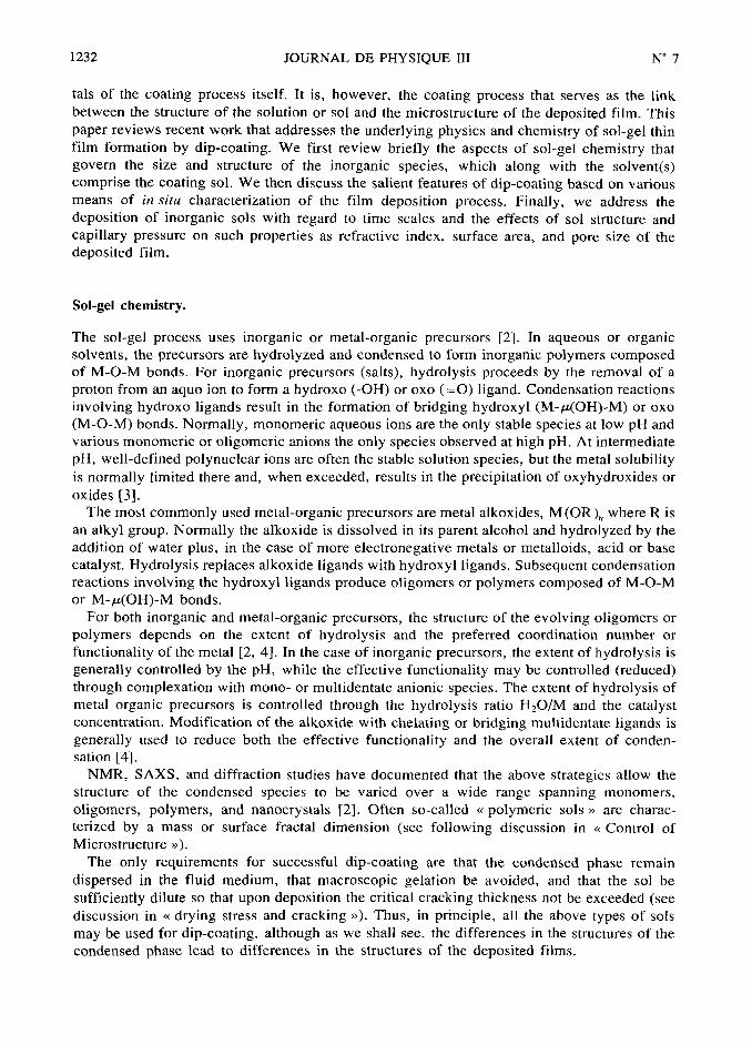
In dip-coating, the substrate is normally withdrawn vertically from the coating bath at a
constant speed Uo (see fig. la) [5]. The moving substrate entrains the liquid in a viscous
boundary layer that splits in two at the free surface (point S in Fig. lb), returning the outer
layer to the bath. Since the solvent is evaporating and draining, the entrained film acquires an
approximate wedge shape that terminates in a well-defined drying line (x=
0 in Fig. la).
Above the stagnation point S (Fig, lb), when the upward moving flux is balanced by that due
to evaporation, the film position and shape of the film profile remain steady with respect to the
coating bath surface. Within the thinning film, the inorganic species are progressivelyconcentrated by evaporation, leading to aggregation, gelation, and final drying to form a type
of a dry gel or xe;ogel.
SOL-GEL DIP-COATING
CapillaryDEPOSITED pressure pc
FILM exer~ec at final'~°~
~ ~stage of drying ~~~
° as menlscl
recede Into
OR PORE FORIIAfiON gel Interior vapor~
Pc= 2y~~cos(@)
I ~~_~
ALCOHOL/V/ATEREVAPORATION
~GRAVITATIONAL
DRAINING
+EVAPORATION
~~~ ~~~
~
[ ]~
PORE SIZE CONTROLLED BYI
~ ~ ~]~
*
=j~u~)2/3/y~~l/6jpg)1/2 S12E, STRUCTURE, COIIPOSIfiON
~~ ~ ~
~ ENTRAINED DILUTE SOL RATES OF CONDENSATION/~ ~
~ ~
~ ~
~~~~~~~,~EVAPORATION
~,~~~~ ~~~SURFACE CAPILLARY PRESSURE
a)
Fig. I. -a) Schematic of the steady-state dip-coating process, showing the sequential stages of
structural development that result from draining accompanied by solvent evaporation and continued
condensation reactions, Uo is the withdrawal speed, h (x) is the film thickness at position x measured from
the drying line ~o, h~ is the entrained film thickness just above the stagnation point S, ~ is the liquidviscosity, p is the liquid density, P~ is the capillary pressure, y~v is the surface tension, and 0 is the
wetting angle. b) Detail of the flow patterns (streamlines) during dip coating. is the boundary layer, and
h i~ the thickness of the fluid film.

1234 JOURNAL DE PHYSIQUE III N° 7
Uo
h
@
S LIQUIDBATH
SURFACE
(i-b-
b)
Fig. I (continuedJ.
When the substrate speed and liquid viscosity h are low, as is normally the case for sol-gel
film deposition, the entrained thickness ho (see Fig. I al is that which balances the viscous drag
ix ~Uo/h), gravity force (pgh), and liquid-vapor s~irface tension y~v, according to the
relationship derived by Landau and Levich [6]
ho=
0.94(~Uo)~~~/Y/((Pg)'~~ ('J
where p is the liquid density and g is the acceleration of gravity.
Pure and binary fluids,
Although the above expression was developed for pure fluids (I.e. those with no condensed
phase), several studies of sol-gel dip-coating have verified the h ccU)~ relationship predicted
by equation (I ) (e.g., Ref. [7]), suggesting that the entrainment of inorganic species has little
effect on the hydrodynamics of dip-coating, at least at the early stages of deposition where the
entrained sol is quite dilute. Thus, some insight into sol-gel film deposition may be gained bycloser examination of the details of gravitational draining and evaporation of pure and binary
fluids as revealed by«
imaging ellipsometry»
[8] and«
fluorescence imaging»
[9] of the
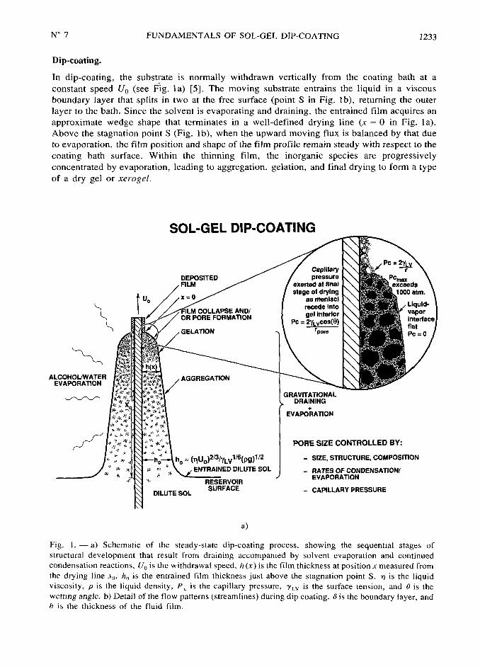
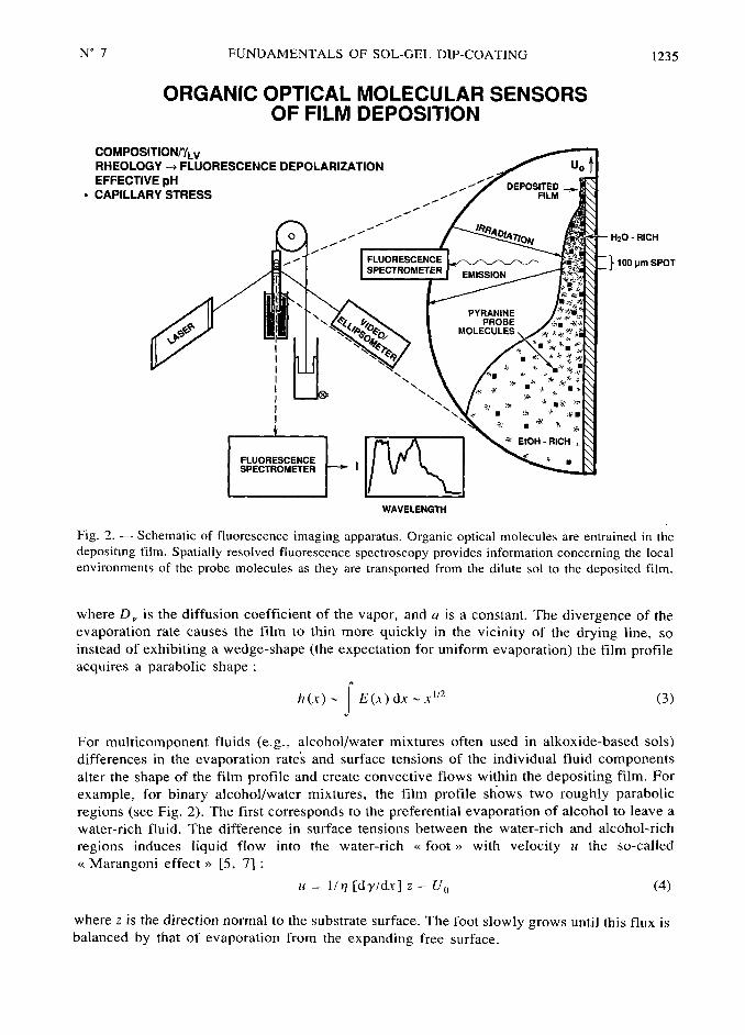
steady state film profile (see Fig. 2). Imaging ellipsometry allows the in situ determination of
film thickness h and film refractive index n over the complete film profile depicted in figure la.
Fluorescence imaging, figure 2, uses entrained organic dyes as molecular sensors of the
progressively changing physical and chemical environments created within the thinning film.
Whereas the entrained film thickness immediately above the stagnation point depends on
hydrodynamic factors, the shape of the film profile h (xi in the vicinity of the drying line is
established by the evaporation rate. Hurd showed that for planar substrate geometry, the
evaporation rate E of a pure fluid was not constant but diverged at the drying line
(x 0, Fig. la) according to the expression [10] :
E (x )=
D~
ax~ '~~ (2)
N° 7 FUNDAMENTALS OF SOL-GEL DIP-COATING 1235
ORGANIC OPTICAL MOLECULAR SENSORSOF FILM DEPOSITION
COMPOSITIONIiLVRHEOLOGY ~ FLUORESCENCE DEPOLARIZATION Uo
EFFECTIVE pH~~~~~,~~
.CAPILLARY STRESS
~~~,
FILM
o
,,,'''''RICH
''FLUORESCENCE i oo ~~ sp~T
EmissioN
,PYAANINE
PROBE
§
,s ~
'
~ ~
~
', ~ ~
' ~~ m~ ~~ /
' ~~
~ ~~ m~
~ ~~
FLUORESCENCE
~ ETCH- RICH
SPECTROMETER
~~ ~
WAVELENGTH
Fig. 2. Schematic of fluorescence imaging apparatus. Organic optical molecules are entrained in the
depositing film. Spatially resolved fluorescence spectroscopy provides information concerning the local
environments of the probe molecules as they are transported from the dilute sol to the deposited film.
where D~ is the diffusion coefficient of the vapor, and ais a constant. The divergence of the
evaporation rate causes the film to thin more quickly in the vicinity of the drying line, so
instead of exhibiting a wedge-shape (the expectation for uniform evaporation) the film profileacquires a parabolic shape :
h ix) lE(,i ) dx >"~~ (3)
For multicomponent fluids (e.g., alcohol/water mixtures often used in alkoxide-based solsl
differences in the evaporation rate's and surface tensions of the individual fluid components
alter the shape of the film profile and create convective flows within the depositing film. For
example, for binary alcohol/water mixtures, the film profile shows two roughly parabolic
regions (see Fig. 2). The first corresponds to the preferential evaporation of alcohol to leave a
water-rich fluid. The difference in surface tensions between the water-rich and alcohol-rich
regions induces liquid flow into the water-rich «foot» with velocity ii the so-called
«Marangoni effect
»[5, 7] :
u=
1/~ [dy/di] z Uo (4)
where z is the direction normal to the substrate surface. The foot slowly grows until this flux is
balanced by that of evaporation from the expanding free surface.

1236 JOURNAL DE PHYSIQUE III N° 7
There are several consequences of preferential evaporation and surface tension gradientdriven flows with respect to sol-gel film deposition
I) it is the composition of the fluid that persists to the drying line that establishes the surface
tension and hence the magnitude of the capillary pressure exerted on the condensed phase(Fig. la). Fluorescence imaging (Fig. 2) performed by Nishida and co-workers [9] has shown
that for ethanol/water/silica sols, the composition of the fluid at x =
0 is greater than 80 %
water, when the initial sol contains only 12.5 volume §b water
it the surface tension gradient-driven flow of liquid through a thin«
neck» can create quite
high shear rates during dip-coating. For the toluene:methanol (50:50) system, the shear rate
resulting from surface tension gradient driven flow is estimated to be 104 s~' [10]. Such
shears could be sufficiently strong to align or order the entrained inorganic species.
Effect of condensed phases,
SoLiDs CONCENTRATION AND TIME SCALE. As the film thins, the entrained condensed
species are concentrated. Above the stagnation point where all entrained species are
incorporated in the final deposited film, a simple flux balance over a horizontal slice leads to
l'0j :
h(.i) w (x)=
Cte + 0 (h~/hj) (5)
where ~b(x) is the volume fraction solids. We see that ~b varies inversely with h, if
h « ho (the normal case for sol-gel dip-coating). This rapid concentration is more evident from
consideration of the mean particle (polymer) separation distance (;), which varies as the
inverse cube root of ~b, or 11") ~,i'~~. This precipitous function implies that half the distance
between particle (polymer) neighbors is traveled in the last 2 §b of the deposition process,establishing a time scale of about 0,I s during which the condensed species are in close
proximity.We anticipate several consequences of the short time scale of the film deposition processes.
I) There is little time available for reacting species to «find
»low energy configurations. Thus
(for reactive systems) the dominant aggregative process responsible for network formation
may change from reaction-limited (near the reservoir surface) to transport-limited near the
drying line, iii For sols composed of repulsive particles, there is little time available for the
particles to order as they are concentrated in the thinning film, iii) There is little time available
for condensation reactions to occur. Thus gelation may actually occur by a physical process,through the concentration dependence of the viscosity rather than a chemical process. (In some
systems this is evident by the fact that the deposited film is quickly re-solubilized when
immersed in solvent II ii. iv) Since the thin physical or chemical gels are likely more weaklycondensed, and hence, more compliant than bulk gels, they are more easily compacted first
by evaporation and then by the capillary pressure exerted at the final stage of the deposition
process (see Fig. la). In such compliant materials the effects of capillary forces are enhanced,
because greater shrinkage precedes the critical point, where the liquid-vapor interface first
recedes into the gel (Fig, la inset), causing the pore size to be smaller and the maximum
capillary pressure to be greater (see following discussion of drying).
STAGES OF DRYING. Scherer Ii 2] divides the drying of gels into two stages a constant rate
period (CRP) and a falling rate period. During the constant rate period, mass transfer is limited
by convection away from the gel surface, whereas during the falling rate period, mass transfer
is limited by the permeability of the gel. Extending these ideas to dip-coating, we might expect
that a CRP would obtain throughout most of the deposition process, since the liquid-vapor

N° 7 FUNDAMENTALS OF SOL-GEL DIP-COATING 1237
interface remains located at the exterior surface of the thinning film except at the final stage of
drying (see Fig, la).
A constant evaporation rate implies a wedge-shaped film profile. This is not observed for
pure fluids, nor is it observed for inorganic sots. The film profile of a titanate sol preparatedfrom titanium ethoxide hydrolyzed under acidic conditions in ethanol is described by
h (xi x° ~~ [5], which indicates that the evaporation rate increases as x -0, although not quite
as rapidly as for pure ethanol (h (xi x° ~ ). Thus even for the deposition of inorganic sols, the
film profile, and hence the concentration profile, are largely established by the dependence of
the evaporation rate on the geometry of the depositing film ('). For sots containing fluid
mixtures of differing volatilities, the fluid composition changes with distance x, contributing to
further changes in the evaporation rate.
The critical point, where the liquid first recedes into the gel (see Fig. la inset) should mark
the beginning of the falling rate period. Depending on the distribution of liquid in the pores, the
drying rate is limited by flow or diffusion. For compliant molecular networks that are collapsedprior to the critical point, drying occurs by Fickian diffusion, if the temperature is above the
glass transition temperature of the mixture [12]. The onset of a falling rate period near the
drying line may account for the differences in the exponents that describe the shape of the purefluid and the titanate sol film profiles.
RHEOLOGY. As the film becomes more concentrated in the condensed phase throughevaporation, the rheological response of the liquid changes from Newtonian to shear thinning(aggregated systems) or thixotropic (ordered systems) and then to viscoelastic. Eventuallygelation extends throughout the film and the material no longer yields I-e- the film behaves as
an elastic solid. It is at this final stage of the deposition process that the capillary pressureP~ created by tiny menisci as they recede into the gel, is maximized (see Fig, la). The
curvature of the menisci causes the liquid to be in tension and the network in compression.Generally the magnitude of the capillary pressure is estimated by the Laplace equation
P~=
2 y~v cos (6 )/r~ (6)
where 6 is the wetting angle and r~ is the pore size. For wetting pore fluids (cos 6-
1),
P~ could approach or possibly exceed 1000 bar, because the pore size may approachmolecular dimensions. The capillary pressure thus represents a very strong driving force to
densify the depositing film.
It is balance between this capillary pressure, which compresses the network, and the
modulus of the network, which enables it to resist collapse, that establishes the final densityand pore size of the film. Initially as the solvent evaporates, the gel is able to shrink. The
volume fraction solids ~b increases, causing the bulk modulus K to increase as a power law. For
both wet and dry silica gels, the following relationship is observed [12]
Kcc ~b~~ (7)
At the same time the spacing between polymers (effective pore size) is decreasing, causingthe maximum possible capillary pressure to increase approximately as II (r)
~b'~~ Thus for
silica films, we expect the modulus to increase more rapidly than the capillary pressure. When
the modulus rises sufficiently to balance the capillary pressure, shrinkage stops, thereby
(') Experiments performed on a variety of substrates, including metals, ceramics, and plastics all
showed similar thickness profiles emphasizing that the evaporation rate not the wetting characteristics are
responsible for determining the profile shape [10].

1238 JOURNAL DE PHYSIQUE III N° 7
establishing the pore size and density. Beyond this so-called critical point any further solvent
loss creates porosity within the film. For systems in which K exhibits a much weaker
dependence on ~b, for example as a consequence of organic modification or complexation of
the metal centers with multidentate, non-hydrolyzable ligands, we might expect the network to
be completely collapsed by the rising capillary pressure. However the rising viscosity
accompanying solvent loss combined with the short time scale of the deposition process may
represent a kinetic limitation to achieving a non-porous state. (It should also be pointed out that
subsequent thermolysis of organic ligands will normally create porosity, even though the as-
deposited film could be considered non-porous).
Drying stress and cracking.
As the film dries, it shrinks in volume. Once the film is attached to the substrate and unable to
shrink in that direction, the reduction in volume is accomodated completely by a reduction in
thickness. When the film has solidified and stresses can no longer be relieved by flow, tensile
stresses develop in the plane of the substrate. Croll [13] estimated the stress («) as
s =
[E/(Iv
)][~f~ f~)/3] (8)
where E is Young's modulus (Pal,u
is Poisson's ratio, f~ is the volume fraction solvent at the
solidification point, and f~ is the volume fraction of residual solvent in the«
dry»
film. The
solidification point was defined for a polymer film as the concentration where the glasstransition temperature has risen to the experimental temperature. Thus stress is proportional to
Young's modulus and the difference between the solvent fraction at the solidification point and
that of the dried coating. Scherer [2, 12] states that the stress in the film is very nearly equal to
the tension in the liquid la=
P~). Despite such a large stress, it is commonly observed that
cracking of films does not occur if the film thickness is below a certain critical thickness
h~ m0.5-1 ~Lm Ii 2]. For films that adhere well to the substrate, the critical thickness for crack
propagation or the growth of pinholes is given by [14, 15]
h~=
(Kj~/«fl )~ (9)
where Ki~ is the critical stress intensity or «fracture toughness
»and Q is a function that
depends on the ratio of the elastic modulus of the film and substrate (for gel films
flm
I). For films thinner than h~, the energy required to extend the crack is greater than the
energy gained from relief of stresses near the crack, so cracking is not observed [12].
When the film thickness exceeds h~, cracking occurs, and the crack patterns observed
experimentally are qualitatively consi~tent with fractal patterns predicted by computersimulation [16]. Atkinson and Guppy [17] observed that the crack spacing increased with film
thickness and attributed this behavior to a mechanism in which partial delamination
accompanies crack propagation. Such delamination was observed directly by Garino [18]
during the cracking of sol-gel silicate films.
Based on equations (8) and (9) above, strategies to avoid cracking include I) increasing the
fracture toughness (Kj~) of the film, it) reducing the modulus of the film, iii) reducing the
volume fraction of solvent at the solidification point, and iv) reducing the film thickness. In
organic polymer films, plasticizers are often added to reduce the stiffness of the film and thus
avoid cracking [19]. For sol-gel systems, analogous results are obtained by organic
modification of alkoxide precursors [20], chelation by multidentate ligands such as p-
diketonates [2 Ii or a reduction in the extent of hydrolysis of alkoxide precursors II 8].
it should be noted that for particulate films Garino [22] observed that the maximum film
thickness obtainable without cracks decreased linearly with a reduction in particle size. Since

N° 7 FUNDAMENTALS OF SOL-GEL DIP-COATING 1239
for unaggregated particulate films, the pore size scales with the particle size, this effect may be
due to an increase in the stress caused by the capillary pressure («m
P~
and/or an increase in
the volume fraction solvent at the solidification point resulting from the manner that the
electrostatic double layer thickness (estimated by the Debye-Huckel screening length) varies
with particle size [23].
Control of microstructure,
The final film microstructure depends on ii the structure of the entrained inorganic species in
the original sol (for example, size and fractal dimension), iii the reactivity of these species (for
example, condensation or aggregation rates), iii) the time scale of the deposition process
(related to evaporation rate and film thickness), and iv) the magnitude of shear forces and
capillary forces that accompany film deposition (related to surface tension of the solvent or
carrier and surface tension gradients). The most common means of controlling the film
microstructure is through particle size. For unaggregated, monosized particulate sols, the pore
size decreases and the surface area increases with decreasing particle size. Asymmetric,
supported membranes have been prepared successfully from particulate sols for use in
ultrafiltration [24]. As noted above difficulties arise when trying to prepare microporous
membranes due to an increased tendency for cracking. Particulate sols may be intensionally
aggregated prior to film formation to create very porous films [25] (e.g., volume porosity
~65 9b). For electrostatically stabilized silica sols, a transition from random-close packing to
ordered packing is observed with increasing substrate withdrawal rates (Uo [25]. This may be
due to a longer time scale of the deposition process (providing more time for ordering) or an
increase in the shear rate accompanying deposition for higher Uo [25].
A second strategy [2] for controlling porosity is based on the scaling of mass
M~ and size r~ of a mass fractal object :
Mi ii (10)
where D is the mass fractal dimension (in three dimensional space, 0~
D~
3). Since density
equals mass/volume, the density p~ of a mass fractal object varies in three dimensional space as
p, ~
i"llr), and the porosity varies as I/p, r)~ ~~. Thus the porosity of a mass fractal object
increases with its size. Providing that such fractals do not completely interpenetrate during film
formation (I,e., they are mutually opaque, requiring D~1.5 [2]), the porosity may be
controlled by the size of the entrained fractal species prior to film formation. The efficacy of
this approach is illustrated in [Ref. [25]] where the refractive index, volume fraction porosity,
pore size, and surface area of a multicomponent silicate film were shown to vary
monotonically with aging time employed to grow the fractal species prior to film deposition.The extent of interpenetration of colliding fractals depends on their respective mass fractal
dimensions and the condensation rate or «sticking probability
» at points of intersection. A
reduction of either D or the condensation rate increases the interpenetration and decreases the
porosity [2, 25]. From equation (10) and surrounding discussion, it follows that to generateporosity using this fractal scheme,
1"~should be rather large, 1.5 « D « 3, and the condensation
rate should be high. Conversely dense films should be formed from small, unreactive
precursors consistent with observations made on a variety of films prepared from chelated
single and multicomponent alkoxide precursors II Ii.
The magnitude of the capillary pressure P~ should also be quite influential in determiningmicrostructure. For bulk gels, elimination of surface tension by removal of the pore fluid above
its critical point [26] results in highly porous aerogels. Deshpande and co-workers have
recently shown that, for aprotic pore fluids, the surface area, pore volume, and pore size of

1240 JOURNAL DE PHYSIQUE III N° 7
bulk silica xerogels are all reduced monotonically by an increase in surface tension of the porefluid [27]. Such studies are more difficult for films, since it is not possible to wash the coatingsol, and distillation of solvents often leads to premature gelation. The most revealing studies
are those comparing the effects of different hydrolysis ratios, H~O/M(OR)~,, on film
properties. Since the theoretical ratio for complete hydrolysis and condensation is n/2, greaterratios must produce
« excess » water. As described above in mixed solvent systems, the least
volatile component survives to the drying line and therefore dictates the magnitude of the
capillary pressure.Fluorescence imaging experiments have shown that for alcohol/water mixtures containing
more than about lo volume 9b water, the composition of the fluid at the drying line is loo 9b
water [9]. We have shown that as the« excess » water is increased from 0.5 to 6.0 volume 9b,
the refractive index of silica films deposited by dipping increases from 1.342 to 1.431,
corresponding to a reduction in porosity from 22 9b to 7 fl [28]. Further increases in the excess
water content cause a reduction in refractive index (increase in porosity). Since water increases
both the surface tension and the extent of condensation of the silicate matrix, this behavior
reflects the competition between capillary pressure, which compacts the film, and aging,which stiffens the film increasing its resistance to compaction. In a similar dip-coating study,Warren and coworkers [29] observed that, for silica films annealed at 800 °C, the dielectric
stength increased and the HF etch rate decreased as the hydrolysis ratio of the coating sol
increased from to 7.5. Further increases caused the reverse behavior. This implies that the
effects of capillarity and aging also strongly influence the subsequent consolidation process.
Finally it is anticipated that shear forces accompanying film formation could influence
microstructure. Although the withdrawal rates Uo are often very low in dip-coating, we have
shown that surface tension gradient driven flows can cause high shear rates (10~ s~ ' ) near the
drying line [28]. Such shear rates might be partially responsible for the ordering of monosized
particulate films [28]. Spin-coating is characterized by higher shear rates. Several studies have
shown that the refractive index increases or decreases with increasing rotational speed [2, 30].
Presumably these conflicting results are explained by the effects of both time scale and shear
on microstructural development increasing the rotational speed increases the shear rate and
reduces the characteristic time scale.
Summary,
It is the sol-gel dip-coating process that serves as the link between the structure and properties
of the liquid precursor sol and the microstructure of the corresponding deposited film. The
steady film profile depicted in figure I spatially resolves the complete sol to gel to xerogel
transformation. Spatially resolved in situ characterization of this deposition process, using
imaging ellipsometry and fluorescence imaging, allows us to gain a fundamental understanding
of the physics and chemistry of sol-gel film deposition as well as to provide insight into sol-gel
processing in general.
Acknowledgements,
This work was supported by the U.S. Department of Energy Basic Energy Sciences Program.
This work was performed at Sandia National Laboratories, a U.S. Department of Energy
Laboratory, under contract number DE-AC04-94AL85000.

N° 7 FUNDAMENTALS OF SOL-GEL DIP-COATING 1241
References
[1] Geffcken W. and Berger E., Deutsches Reichspatent 736411, May 6, 1939, assigned to Jenaer
Glaswerk Schott & Gen., Jena.
[2] Brinker C. J. and Scherer G. W., Sol-Gel Science (San Diego, Academic Press, 1990).
[3] Baes C. F. and Mesmer R. E., The Hydrolysis of Cations (New York, Wiley, 1976).
[4] Livage J., Henry M. and Sanchez C., Sol-Gel Chemistry of Transition Metal Oxides, Prog. Solid
St. Chem. 18 (1988) 259-342.
[5] Brinker C. J., Hurd A. J., Frye G. C., Schunk P. R. and Ashley C. S., Sol-Gel Thin film Fomiation,
J. Ceiam. Soc. Jpn 99 I991) 862-877.
[6] Landau L. D. and Levich V. G., Dragging of a liquid by a moving plate. Acta Phys. Chim. URSS 17
(1942) 42-54.
[7] Brinker C. J., Hurd A. J., Schunk P. R. and A~hley C. S.. Review of Sol-Gel Thin Film Formation,
J. Non. Ciyst. Solids 147 &148 (1992) 424-436.
[8] Hurd A. J. and Brinker C. J., Optical Sol-Gel Coatings Ellipsometry of Film formation, J. Phys.
Franc-e 49 (1988) 1017-1025.
[9] Nishida F., Dunn B., Mckiernan J. M., Zink J. I., Hurd A. J. and Brinker C. J., in situ Fluorescence
Imaging of Sol-Gel Thin Film Formation Proceedings of VIIth Intl. Workshop on Glasses and
Ceramics From Gels, July 19-23, 1993, Paris, France to be published (1993).
I10] Hurd A. J., Evaporation and surface tension effects in dip coating, Adv. Chem. Series No. 234, Am.
Chem. Soc., to be published January (1994).
[I Ii Schwartz R. W., Voigt J. A., Buchheit C. D. and Boyle T. J., Densification and crystallization of
zirconia thin films prepared by sol-gel processing, Ceramic Transactions-Proc. Am. Ceram.
Soc. PAC RIM Mtg., Honolulu, HI (November, 1993) submitted.
[12] Scherer G. W., Recent Progress in Drying of Gels, J. Non-Cjyst. Solids 147 & 148 (1992) 363-374.
[13] Croll S. G., The Origin of Residual Internal Stress in Solvent-Cast Thermoplastic Coatings, J. Appl.Polymer St-I. 23 (1979) 847-853.
[14] Evans A. J., Dory M. D, and Hu M. S., The Cracking and Decohesion of Thin Films, J. Mats. Res.
3 (1988) 1043-1054.
[15] Thouless M. D., Decohesion of Films with Axisymetric Geometric~, Acta Metall. 36 (1988) 3131-
3139.
[16] Meakin P., Models for Materials Failure and Deformation, Science 252 (1991) 226-229.
[17] Atkinson A, and Guppy R. M., Mechanical Stability of Sol-Gel Films, J. Mater. Sci. 26 (1991)3869-3875.
[18] Garino T. J., The Cracking of Sol-Gel thin films During Drying in Better Ceramics ThroughChemistry IV, 180 (1990) 497-502, MRS.
[191 Cohen E. D., Gutoff E. B, and Lightfoot E. J., in Proc. 1990 Int. Symp. on Mechanics of Thin Film
Coating, AIChE Spring Mtg. Orlando FL (March 1990).[20] Schmidt H., Rinn G., Nass R. and Sporn D., Film Formation by Inorganic-Organic Sol-Gel
Synthesis, in Better Ceramics through Chemistry III 121 (1988) 743-752. MRS.
[21] Takahashi Y., Matsuoka Y., Yamaguchi Kouichi, Matsuki M. and Kobayashi K., Dip coating of
PT, PZ, and PZT films using an alkoxide-diethanolamine method, J. Mate;. Sci. 25 (1990)3960-3964.
122] Garino T. J., PhD Thesis, MIT (1988).[23] Brinker C. J. and Scherer G. W., Sol-Gel Science chap. 4 (Academic Press, San Diego, 1990)
pp. 235-301.
[24] Many examples are provided in R. R. Bhave, Ed., Inorganic Membranes (Van Nostrand Reinhold,New York, 1991).
[25] Brinker C. J., Hurd A. J., Frye G. C., Ward K. J, and Ashley C. S., Sol-Gel Thin Film Formation,J. Non-Cryst. solids 121 (1990) 294-308.
[26] Brinker C. J, and Scherer G. W., Sol-Gel Science chap. 8 (Academic Press, San Diego, 1990)
pp. 493-505.

1242 JOURNAL DE PHYSIQUE III N° 7
[27] Deshpande R., Hua D.-W., Smith D. M. and Brinker C. J., Pore Structure Evolution in Silica Gels
during Aging and Drying : 3. Effects of Surface Tension, ,f. Non-Ciy,it. solids 144 (1992) 32-
43.
[28] Brinker C. J., Frye G. C., Hurd A. J. and Ashley C. S., Fundamentals of Sol-Gel Dip Coating, Thin
Solid Films 201(1991) 97-108.
[29] Warren W. L., Lenahan P. M., Brinker C. J., Shaffer G. R., A~hley C. S. and Reed S. T., Sol-Gel
Thin Film Electronic Properties, in Better Ceramics Through Chemistry IV 180 (1990) 413-
4l9, MRS.
[30] Glaser P. M. and Pantano C. G., Effect of the H~O/TEOS ratio upon the preparation and nitridation
of silica sol/gel films, J. Non-Ciyst. Solids 63 (1984) 209-215.