of pressure-time history boom shock … · mathematical methods are presented for computing the...
TRANSCRIPT

8
NASA CR-66169
COMPUTATIW OF THE PRESSURE-TIME HISTORY OF A SONIC BOOM
SHOCK WAVE ACTING ON A YINDOW GLASS IN A BUILDING
By 61en W . Zumwalt
Distribution of th is report is provided in the interest of information exchange. resides in the author or organization that prepared it.
Responsibility for the contents
GPO PRICE S . m CFSTl PRICE(S) S e s
ITHRUI
N66 3 8 7 5 4 U C C E S S I O N NUMBER) -
1 I- - Hard copy (HC) E afl
Microfiche (MF) ,3v ‘‘2s (PAGES1
1
(CATEGORY) i
-f ff653 July65
Prepared under Contract ANDEMS ASSOCIATES, IN€. OklahaRIzl City, Oklahoma
far
NATIONAL AERONAUTICS AND SPACE ADMINISTRATION
8
https://ntrs.nasa.gov/search.jsp?R=19660029464 2018-08-26T06:55:09+00:00Z

I -
COMPUTATION OF THE
PRESSURE-TIME HISTORY OF A SONIC BOOM
SHOCK WAVE ACTING ON A WINDOW GLASS I N A BUILDING
By Glen W. Zumwalt
SUMMARY
Mathematical methods a re presented for computing the pressure-time h i s to ry of a sonic boom shock wave ac t ing on any given e x t e r i o r w a l l surface facing the shock wave. receive r e f l ec t ed wave e f f e c t s from nearby w a l l s o r corners, addi t iona l methods a re presented. bui lding w a l l a t which i t is believed the window g la s s w a s broken by a s p e c i f i c sonic boom from one test f l i g h t during t h e series of 1,253 sonic boom test f l i g h t s a t Oklahoma City i n 1964.
Also, f o r w a l l s which are i n t h e "shadow" of the shock wave or which
These methods are applied to a s p e c i f i c window loca t ion of a
The calculated pressure-time h is tory ac t ing on t h i s window glass locat ion, from t h i s p a r t i c u l a r sonic boom, indicates t h a t no abnormal o r unusual pressure- t i m e condi t ion would have been produced. However, these ca lcu la t ions are based on several assumed atmospheric conditions and f l i g h t da t a values of which some a re of doubtful va l id i ty .
INTRODUCTION
During the series of sonic boom test f l i g h t s conducted i n the Oklahoma City area during 1964, an 8' x 10' x 1/4" p la te g lass window i n the s t o r e f ron t of a s ingle-s tory comnercial bui lding w a s broken coincidental ly with the occurrence of one of t he sonic booms. See Figure 1.
This p a r t i c u l a r sonic boom occurred at about 1:20 p.m. on Sunday, May 17, 1964 and w a s produced by an F-101 a i r c r a f t at 40,000 f e e t a l t i t u d e on a scheduled steady-state course a t a scheduled speed of Mach 1.4. of a i r c r a f t course with respect to the building are shown i n Figure 11.
Orientat ion and d is tance
Using t h i s s p e c i f i c inc ident as an example, an attempt has been made t o develop methods f o r pred ic t ing , o r estimating, the pressure-time h i s t o r y ac t ing on bui lding w a l l s i n general when exposed t o sonic boom shock waves. pressure-time h i s to ry is considered t o include both bow and t a i l inc ident waves plus t h e i r respect ive r e f l ec t ed waves.
The
F i r s t considered is the time-of-passage of an incident wave and the t i m e i n t e r v a l between inc ident and r e f l ec t ed waves f o r a w a l l facing the wave. This includes the following variables: a i r c r a f t ve loc i ty , a l t i t u d e , and d i r ec t ion ; w a l l angle, s lope, and o f f s e t dis tance from the f l i g h t t rack . No wind e f f e c t is
1

included, but three atmospheric temperature models are used in the analysis.
The second analysis is concerned with N-wave diffraction and reflection around structures. The two-dimensional theory of Keller and Blank (Ref. 2) is adapted to produce a series of pressure perturbation expressions for multiple wave reflections.
The two analyses are applied to the location of the broken window in the ~
example store front. sufficient size to place it in the "shadow" of the shock wave, it provides almost all of the complications which can occur. for the four corner points and the mid-point position of the window location. Since a two-dimensional analysis is used for the diffraction process, some idealization of the model was necessary.
Since the window location is under an overhanging roof of
Pressure-time histories are computed
A discussion is presented of a three-dimensional mesh-point computation technique which would permit treatment of three-dimensional, non-steady waves with arbitrary wall placement.
Purpose of this paper is intended to provide additional background infor- mation for further development of effective methods for predicting, investigating and evaluating possible sonic boom damage to window glass.
Figure 1 - Store front of the commercial building in which an 8 ' x 10' x 1/4" window glass was broken coincidentally with occurrence of a sonic boom. Third large pane from right is the location of broken window.
2

SYMBOLS FOR COMPUTATION OF SONIC BOOM WAVE PASSAGE TIMES ON A WALL
a
D gv
D PV
H
L
m
M
S
t
T
P ATir
V
X
Y
yC
z
6
8
T
speed of sound ("acoustic velocity"), feet/second
horizontal dis tance between the ver tex of the sonic boom wave and i t s ground in t e r sec t ion point, g. ( f ee t )
horizontal dis tance between a w a l l point , P , and the ver tex of the sonic boom wave, at the in s t an t P i s in te rsec ted by the incident wave. ( f ee t )
height of the w a l l , f e e t
length of the wall , f e e t
coef f ic ien t of acoust ic ve loc i ty va r i a t ion with a l t i t u d e , feet/second-feet
Mach number
projected dis tance of the wave from the f l i g h t path i n the YZ plane; see Figure 3 . ( fee t )
t i m e var iab le , seconds
t i m e for a wave t o pass a point a f t e r the a i r c r a f t passes t h e coordinate or igin. (Subscripts ind ica te incident o r re f lec ted wave; second subscr ipt indicates the point.) (seconds)
t i m e in t e rva l between the passage of the incident and r e f l ec t ed waves a t a point , P, on a wall. (seconds)
f l i g h t ve loc i ty , feet/second
coordinate ax is , horizontal and along the f l i g h t t rack on the ground.
coordinate axis, horizontal and perpendicular t o the f l i g h t t rack . distance along the Y-axis t o the neares t c o m e r of the w a l l on the ground.
coordinate axis , v e r t i c a l .
Mach angle or incident wave angle measured from the horizontal .
angle between the w a l l and the Y ax i s , measured clockwise from the Y ax is i n the horizontal plane.
time a t which a pressure disturbance wave w a s emitted. (seconds)
3

4 angle between t h e w a l l and the hor izonta l (X,Y) plane.
Subscripts :
C a t point c y the lower corner of t h e w a l l which i s the most "upstream" i n the f l i g h t d i r ec t ion .
d a t point d , the o r ig in of the disturbance ray.
g a t ground l eve l point g, d i r e c t l y under the poin t P.
i incident wave.
P a t point P on the w a l l .
r r e f l ec t ed wave.
t a t the tropopause, or a t the t i m e a ray passed the tropopause plane.
V a t the ver tex of the shock cone.
mMBOLS FOR DIFFRACTION AND REFLECTION OF SONIC BOOM WAVES BY CORNERS AND WALLS
a
b
C atmospheric ve loc i ty of sound, feet/second
angle between w a l l and normal-to-wave
angle between wall and normal-to-wave
f i r s t disturbance circle
second disturbance circle
th i rd disturbance circle
fourth disturbance circle
c1
c2
c3
c4
H height of a w a l l , f e e t
n d i rec t ion normal t o a w a l l
P
P pressure (psfa)
P-Po
pl-po pressure perturbation = - (..,nensionless)
atmospheric pressure (psfa)
pressure behind the inc ident wave (psfa) p1
4

r
S
S
t
W
X
x1
y1
a
Y
2
9
f4
P
9
transformed r a d i a l coordinate (see equation 4)
transformed t i m e coordinate (see equation 4)
cross-sect ional area of a ray tube, f e e t
time var iab le , seconds
transformed complex plane (see equation 11)
coordinate axis along the l i n e of symmetry of a wedge o r comer
coordinate ax is along a horizontal wall
coordinate axis perpendicular t o X
coordinate ax is along a vertical w a l l
complex var iable (see equation 10)
see equation 11
angle var iable; clockwise from the X-axis
half-angle of a w a l l o r corner; clockwise from X - a x i s
see equation 7
ray angle; clockwise from X-axis
2
Subscripts:
0 i n undisturbed atmosphere
1 behind incident wave
2 behind re f lec ted wave
i incident wave
r ref lec ted wave
5

COMPUTATION OF SONIC BOOM WAVE PASSAGE TIMES ON A WALL
The purpose of t h i s sec t ion i s t o develop a method f o r es t imat ing the pres- sure-time his tory a t any point on a bui lding due t o the passage of a sonic boom wave. To determine the t i m e of passage of bow and t a i l waves and t h e i r re f lec- t i ons , t he geometric r e l a t ions between w a l l and wave must be known f o r a given a i r c r a f t a l t i t ude , d i rec t ion , and speed. Three methods were attempted, ranging from a simple, highly ideal ized model t o a more realistic, but complex, ana lys i s .
Method I
An approximate method w a s developed t o pred ic t the t i m e h i s to ry of incident and re f lec ted sonic boom waves on a plane w a l l . The simplifying assumptions made here were (a) t h a t the speed of sound of the conical wave i s constant and equal t o t h a t a t ground l eve l , and (b) t h a t no wind e f f e c t s are present . The wave then can be considered t o be t r u l y conical i f the a i r c r a f t i s i n s teady, l eve l f l i g h t .
The coordinate axis system f o r an a r b i t r a r i l y or iented plane wal l i s shown i n Figure 2. c r a f t i n steady, l eve l f l i g h t a t a l t i t u d e Zv, f l y ing with a ve loc i ty V p a r a l l e l
t o the X-axis. The horizontal dis tance of the e f f e c t i v e ver tex of the cone from a f ixed or igin "O", a t the t i m e the wave passes a given loca t ion on the w a l l , can be estimated. For a known geometry and forward
speed of the a i r c r a f t , the t i m e h i s to ry of an incident wave on a plane w a l l can
The bow and t a i l waves are assumed to have been produced by an air-
This dis tance i s designated Xv.
then be computed.
z
/ Y L
Figure 2 -Coordinate axis system f o r an a r b i t r a r i l y or iented plane w a l l .
6

With reference t o Figure 3 :
I
Ti P xv/v
= X + D (2)
( 3)
xV P PV c o t 4 X (Y -Y Tan 8 + Zp cos e
P P C
The four equations can be combined to give the t i m e the incident wave reaches point P on the w a l l :
'I = - L [ ( y - Y ) T a n B + 2 p c o t 4 +*' + (2"- z 1 cos e Tan B V P C P
Ti
The t i m e Ti
The time i n t e r v a l between the incident and r e f l ec t ed waves passing P i s
is referenced t o the passing of the a i r c r a f t over o r ig in , 0 . P
t w i c e the t i m e i n t e r v a l from P t o the ground d i r e c t l y beneath:
Thus: 2 = -
P v (Dgv- Dpv' c 1
Tir
Ti
P
and ATir values f o r a l a r g e number of po in ts , P, on a w a l l w i l l give a P P
clear p ic tu re of t he t ime-history of the inc ident and r e f l ec t ed waves f o r a w a l l which is s t ruck by an undisturbed wave. This does not , of course, apply t o w a l l which would be i n the "shadow".
Tir p lays an important r o l e i n the s t r u c t u r a l response. From equation P ( lo) , i t can be seen t h a t t h i s t i m e i n t e rva l increases with height of t he w a l l
point above ground level and decreases as the o f f s e t d i s tance from the f l i g h t t rack increases .
7
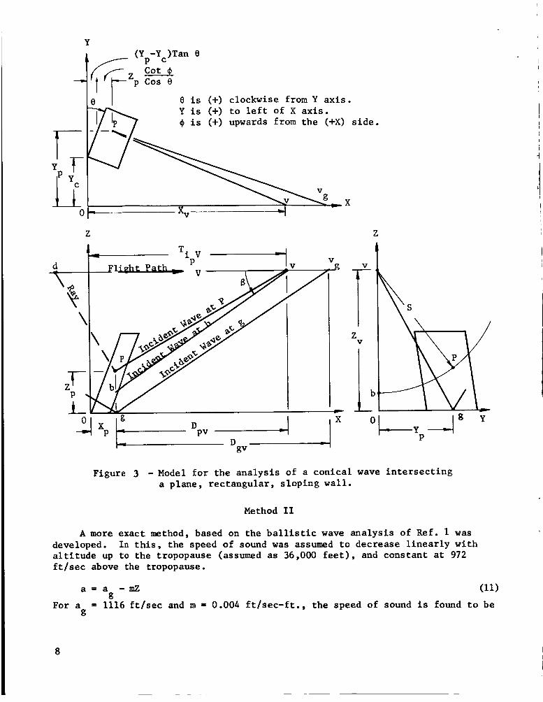
Y (Y -Y )Tan 0
P C
0 i s (+) clockwise from Y ax i s . Y i s (+) t o l e f t of X axis .
e 1 i s (+) upwards from the (+X) s ide .
Z Z
Figure 3 - Model f o r the analysis of a conical wave in t e r sec t ing a plane, rectangular , sloping w a l l .
Method I1
A more exact method, based on the b a l l i s t i c wave analysis of Ref. 1 w a s developed. a l t i t u d e up t o the tropopause (assumed as 36,000 f e e t ) , and constant a t 972 f t / s e c above the tropopause.
I n th is , the speed of sound w a s assumed t o decrease l i nea r ly with
a = a - m Z (11) g
For a = 1116 f t / s e c and m = 0.004 f t / sec- f t . , the speed of sound i s found t o be g
8

very near t h a t of the standard atmosphere; see Figure 4 ,
c
1 .
m
c) al I
k 9) a U al al YI
-0 E 7 0 00
w 0
m al al a cn
1150
1100
1050
1000
950
a - a - O.004Z
0 5 10 15 20 25 30 35 40 45
A 1 ti tude, thousand f e e t
Figure 4 - Speed of sound vs. a l t i t u d e .
F l i g h t a l t i t u d e s below the tropopause, - The shape of the wave f r o n t s pro- duced by a point disturbance i s obtained by f inding the system of surfaces which are orthogonal t o rays from t h a t point. propagates from a poin t , along a given ray, it is possible t o relate the shape of t he wave f r o n t s t o the growth of these f ronts . sonic speed decreases l i n e a r l y with a l t i t ude , the disturbance f r o n t coordinates (X,Y,Z,) are given by:
By following t h a t disturbance as it
I n an atmosphere i n which the
~
a (X-Xd)2 = (Y-Yd)2 + 1)12 = 3 S i n h h t m
The coordinates are as shown i n Figure 3 , except t h a t , f o r a non-constant- temperature atmosphere, the ray and wave l i n e s are not s t r a i g h t , In equation (12), t is the time s ince the disturbance w a s i n i t i a t e d . Considering a f ixed coordinate system as shown i n Figure 3 , the disturbance o r ig in , point d , be- comes a function of t i m e . Then a t time t , the pos i t ion of the wave f ron t (X,Y,Z) emitted by the a i r c r a f t at an e a r l i e r t i m e T is given by:
(X-Xd)2 + (Y-Yd)2 + [Cosh m ( t - t ) - 1 ])p = 2 Sinh%(t-r) (13)
where: a = a - mZv and Xd, Yd, and Zd are functions of t. v g
9

The envelope of t h i s system of wave f ron t s i s obtained by e l imina t ing T be- tween equation (13) and i ts p a r t i a l de r iva t ive with respect t o Z . en t i a t ion gives:
This d i f f e r -
a -2 (X-Xd) id-2 (Y-Y,) fd-2 (Z-Z, + 7;; V [Cosh m (t-f)-l]\
- J
{id+id b o s h m (t-'t) - 1 +av Sinh m (+-TI = 3' } 1
Yd = 0 (by coord. system)
Zd = constant =
a V -2 m Sinh m (t--T) Cosh m (t--T) + id Sinh m (t--T)
For steady, level f l i g h t : Xd = V
Yd = 0 .
zV 0
Zd = 0
Equation (14) then becomes
bosh m (t--T) - a Sinh m (t--T) = m
Sinh m (t--T) Cosh m (t--T) - a$ m
Simplifying: a
V (Z-Zv - ) Sinh m (t--T) 1 M X'Xd - - -
Combining (13) and (15) : 2 2 a
Sinh2m (t--T)+Y2 + + m [Cosh m (t--T) - l]}
aL
m V = - Sinh2m (t--T)
v 1 - - 1
a (z-zd - 2 ) Cosh m (t--T) + 2aV - Sinh2m(t-T) = o m m
10
a (Z-Zv- ;;;- m m
v 2 2aV V a
) Cosh*m (t-f) + - (Z-Zv- - ) Cosh m (t-r) + 1
a2 v 2 1 a Y 2 + (Z-Zv- ;;;- 1 [ 1 - 3). 5 = 0

By t h e quadrat ic formula: M2av
Cosh m(t-7) = - - m a 2 - - V I
g (Z-Zv - - m 1 a v 2
y2 + (Z-Zv - m 1 (1- 9 1 + 2
M2av a Simp 1 i f y ing:
Cosh m(t-1) = - m
n Cosh m(t - r ) - m
For ZeZ the (+) s ign appl ies before the r a d i c a l in (17). d’
culated by (17).
For given values of Y = Y Z - Z Zv, and M, values of ( t - T ) can be cal- P’ P’ P
The t ime-his tory of an inc ident wave is then given by:
1 Ti = v - ‘XP + D 1 Pv
(X -x 1 -pd + ( t -T Ip V
P For the t i m e i n t e r v a l between incident and r e f l ec t ed w a v e s ,
P
Equation (15) w i l l give (X -X ) for t he se lec ted Zd, with ( t i ) from (17). P d
2 ( 9 )
Tir - - 7 mPv - DPV)
P For t h i s l inearly-varying speed of sound atmosphere,
D = ( t -T )p V - (X -X ) and D = (t-T) V - (X -X ) (19) & (20) PV P d gv g g dg The (X -X
Y - Y = Y a n d Z = Z - 0 . g P g
) term can be obtained from (15) ; one can solve (17) f o r (t-?) with dg g
F l i n h t a l t i t u d e above the tropopause. - A n explicit so lu t ion is not pos- s i b l e f o r a given o f f s e t dis tance from t h e f l i g h t t rack. posed, however, which w i l l permit the computation of l o c a l pos i t ions and times of the wave.
is the a l t i t u d e of the tropopause (here assumed
as 36,000 f e e t ) , the speed of sound w i l l be assumed t o be constant. turbance envelope a t time t f o r a point disturbance emitted by the a i r c r a f t a t time T is a cone:
A method w i l l be pro-
For Z > Z > Z where Z v - - t’ t The d is -
( x - x ~ ) ~ + ( Y - Y ~ ) ~ + ( z - z ~ ) ~ = a(: ( t - r )2 (21)
11
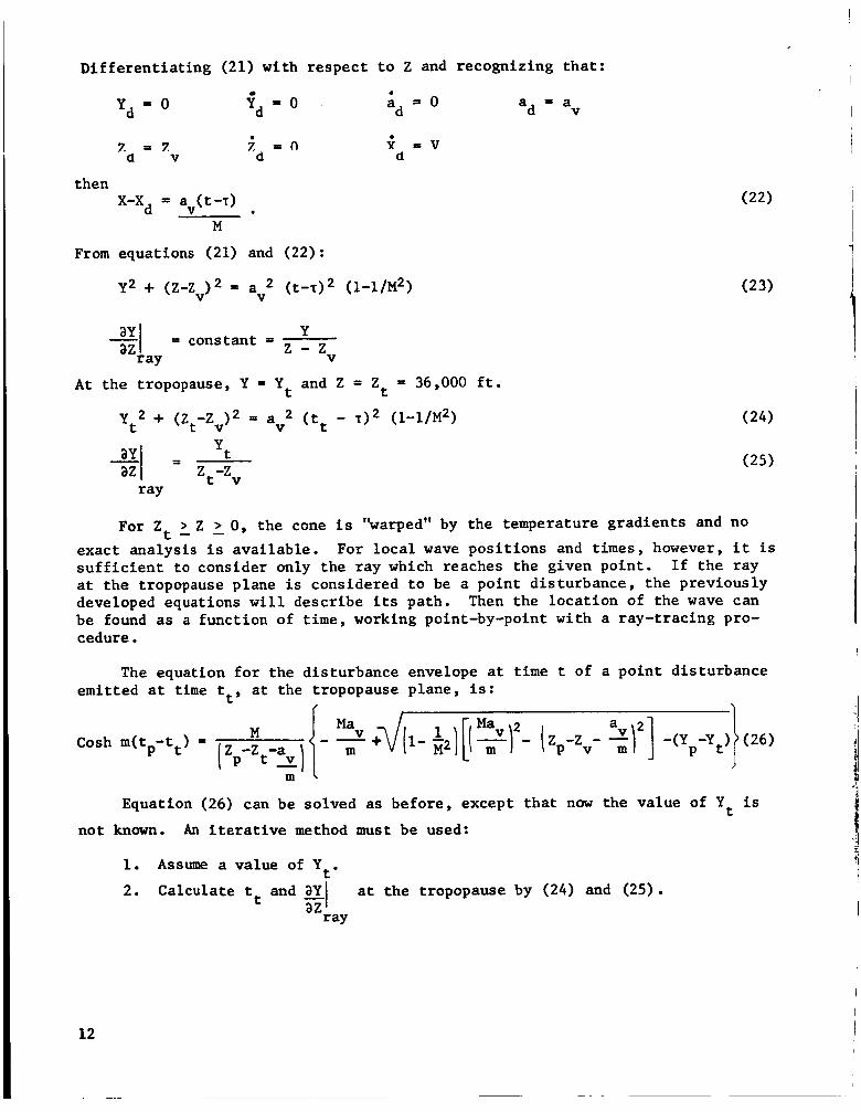
Differen t ia t ing (21) with respect t o Z and recognizing tha t : I . l
a = a d v Yd - 0 Yd - 0 ad = 0
7 = 7 a V
. z = n
d
then X-Xd = av(t-T)
M
. x = V d
From equations (21) and (22):
~2 + (z-zV)2 = av2 (t-T>2 (I-I/M~) (23)
Y z - zv 21 = constant = az
ray A t the tropopause, Y = Y and Z = Z t = 36,000 f t . t
yt2 + (z -z )2 = av2 ( t t - ~ 1 2 (1-1 /~2) t v
ay/ = yt z -z t v az
ray
For Z t Z 0, the cone i s "warped" by the temperature gradients and no
exact analysis i s avai lable . s u f f i c i e n t t o consider only the ray which reaches the given point. I f the ray a t the tropopause plane i s considered t o be a point disturbance, the previously developed equations w i l l describe i t s path. Then the locat ion of the wave can be found as a function of time, working point-by-point with a ray-tracing pro- cedure.
For loca l wave posi t ions and t i m e s , however, i t i s
1
The equation f o r the disturbance envelope a t t i m e t of a po in t disturbance , emitted a t time tt , a t the tropopause plane, is: I
I { I 1
a (1- $I[[ MaV yr- ( z -Z - 2r] -(Y -Y ) P v m P t
M Cosh m(tp-tt) =
m ' "I
Equation (26) can be solved as before, except t ha t now the value of Y i s t not known. An i t e r a t i v e method must be used:
t ' 1. Assume a value of Y
2. Calculate tt and a Y a t the tropopause by (24) and (25). -I az ray
12

3. Assume t ha t the slope w i l l be constant f o r a se lec ted AZ in t e rva l .
ay az Y-Yt = - AZ
4. ous sect ion.
Calculate (t-t,) using (261, and the techniques explained i n the previ- Calculate the new wave-slope as follows:
From equation (16), a can be evaluated f o r t he disturbance envelope which az
is =veq-&ere p e q e i d i c u l a r tc tfre rz3s. t o Z f o r a point disturbance a t Xt, Y,, Zt:
Then differe=tiatiag (16) w i t 5 respect
t Cosh m(t-7)= 0 (29) a t a
I m m t a
$(z-zt- 2 ---I sinhZm(t-d+ 2(y-yt)ay + 2(z-zt- -I+ 2 - aZ d i s t .
envel . Since = - 1,
aZdis t . aZray envel . .
5 . puted Y does not give the desired location P f i v e s t eps
Repeat s teps 3 and 4 u n t i l t he desired Z value is obtained. If the com- select a new Yt and repeat the
P'
6 . When the locat ion has been obtained t o s u f f i c i e n t accuracy, the Ti value is computed by (18) except now: P
Find (X -X ) from (15) wi th Xt, Zt, and tt. P t a
V (X -x ) = M ( t t - t d
7. For the g locat ion, s teps 1 through 5 must be performed again, with a l l p subscr ip ts replaced by g. D can now be found with ( t - T) and (X -X ) as
w a s done f o r p in Step 6. gv f.3 g dg
8 . Compute ATir by ( 9 ) . P
Using an IBM 1620 computer and 500 ft. i n t e r v a l s f o r AZ, about 70 seconds w a s required f o r each complete i t e r a t i o n f o r a 50,000 foot a l t i t u d e .
13

Method 111
A t h i r d method was developed which attempted t o reduce the computer time The simplifying required by Method I1 without s a c r i f i c i n g too much accuracy.
assumption added was t h a t
a l t i t u d e , while the linear va r i a t ion of speed of sound with a l t i t u d e below the
of the ray was constant a t the value of the f l i g h t az
tropopause was retained. S
S i s the projected dis tance of the wave from the f l i g h t path i n the YZ plane; see Figure 3.
F l igh t a l t i t udes below the tropopause. - dS = (dY2 + dZ2) = - dZ
Assuming: Y-Yv
, and Y i s zero by the coordinate system, "1 = constant = - dZ z-zv V ray
d S - - d Z d 1 + ( Y ) 2 z-zv For the l i nea r sonic speed var ia t ion : a = a - mZ
g da d a = - m d Z o r Z = - - m 1 a
(33)
(34)
(35)
From equations (32) through (35), the t i m e in te rva l . f rom a i r c r a f t overhead pas- sage u n t i l wave passage a t point P can be calculated:
ma da] = - x '[ + q y ) 2 p l + ( -
a P V Ti v
P V

and :
\Jvl,a2, P w + V l n (38) P
From (361, (371, and (381, Ti and ATir can be computed. P P
Flight altitudes above the tropopause. -
st Zt
z -z 1 tz B =lv T Z B t d1 + (dkp = t v
By assumption: yt Y - m P Zt-Zv z -2
P V S
v +7/v2,2 v +-I/=
V
P
d w z -z [ ~ ~ - - d q + Vln P V
St (as in equation (36)
Then (39) becomes:
) Tan 8 + Zp cos V
(39)
( 4 2 )
15

These values can be used t o obtain the fncident-to-reflected t i m e i n t e rva l :
Method 111 i s much more straightforward t o compute than Method 11, but the assumption of constant ray angle places i t s accuracy i n doubt. Therefore, a number of typical cases were computed by the three methods t o provide a compar- ison of the r e su l t s .
Computed r e s u l t s by the three methods. - To compare the three methods, com- putat ions were performed f o r a pos i t ion on a v e r t i c a l w a l l 100 f e e t above ground leve l . The ground l eve l was taken as being a t sea l e v e l , and f l i g h t a l t i t u d e s of 70,000, 36,000, and 20,000 f e e t were used. For f l i g h t Mach numbers of 1.5, 2.0, and 3.0 and o f f s e t dis tances , Y from 0 t o 70,000 f e e t , the th ree methods
gave values of incident wave a r r i v a l t i m e , Ti , and t i m e i n t e r v a l between
incident and re f lec ted waves, ATir . Figures 5 , 6 , and 7 show T and
Figures 8 , 9 , and 10 show ATir .
P * P
i P P
P For s m a l l o f f s e t dis tances , the three methods give almost i d e n t i c a l r e s u l t s .
The differences a re grea tes t a t low Mach numbers and la rge Y values. Method I,
the conical wave analysis , gives the poorest accuracy, i f i t is assumed t h a t Method I1 i s the most exact of the three. Method 111, which i s considerably eas i e r t o calculate , appears t o be nearly equivalent t o Method 11, and is the one recommended f o r use.
P
It should be emphasized t h a t no accounting f o r wind has been taken, and t h a t a l i nea r va r i a t ion of acoust ic veloci ty with a l t i t u d e was assumed.
Converting wave t ime-histories i n t o wave geometry. - For the Kinney Shoe Store , the predicted posi t ion of the wave r e l a t i v e t o the bui lding was needed, as w e l l as the time-of-passage of the waves a t s p e c i f i c locat ions. The geometry can be found from the t i m e values as described below.
To determine the angle between wave and w a l l i n a hor izonta l plane, compute the T . values f o r two points on the wall i n the same hor izonta l plane, as f o r
example, the lower corners of a building. i s L , and the point having the smaller Y coordinate i s point 1 and the l a rge r i s point 2 , t h e XY plane i s shown i n the following sketch.
1 I f the dis tance between these points
* For these curves, the t i m e reference f o r T i s the t i m e the wave passes the i
coordinate origin. P
16

angle angle
X
It can be shown, by use of the l a w of s ines , t h a t the w a v e angle i s
V - Ti,) Tan = Tan 9 - (%c 8) (Ti .. L 1 Simi lar ly , two poin ts can be chosen on a vertical l i n e , such as the upper
and lower po in t s of the corner of a building, w i t h t h e upper designated 3 and the lower 4. (i.e., a t an angle gW + 90" from t he P axis) is as shown.
Then, a vertical plane perpendicular to the wave l ine found above
/ 2 Then, f o r a w a l l height H,
These r e l a t i o n s w e r e applied t o t h e Kinney Shoe Store conditions.
-T ) and (T -T ) were found t o be 0.0031 and 0.0014 seconds, respect-
For this, the geometry is shown in Figure 11, and TP 70 f t . , H= 12.75 f t .
ively. From t h i s ,
Values of
(Ti2 i l 24 1 3
wave (8-e") = 3.2O. The wave elevation angle is = 70.1". The r e s u l t i n g wave- I
is found t o be 26.8', making the angle between w a l l and 1
1 building r e l a t ionsh ip is shown i n Figure 12 and some wave-time pos i t i ons are depicted i n Figure 13.
From test da t a f o r t h e F-101 aircraft a t t h e f l i g h t Mach number, a l t i t u d e , and the Y dis tance , the bow-to-tail wave t i m e i n t e r v a l w a s estimated t o be 0.135 seconds. bTir,for 6.0 and 12.75 f e e t he ights , t he pressure h i s t o r i e s shown i n Figure 14
could be predicted.
Upon computing the incident-to-reflected wave time i n t e r v a l ,
I I
17

40
35
4 30 8 0 al fn a al $ 25 3 U 0 al .d
2 .d 20
B
rl 15 2 2 da 10
v( 0
4 U
r( &
n
H
5
0
height of point above ground leve l = 100 fe
10 20 30 40 50 60 70 Y Off-set distance from f l i g h t track, thousand feet P’
Figure 5 - Comparison of incident wave arrival time by three methods for f l i ght altitude of 70,000 feet.
I 18

0 10 20 30 40 50 60 70 Y Off-set distance from f l ight track, thousand feet P'
Figure 6 - Comparison of incident wave arrival time by three methods for f l ight altitude of 36,000 feet.
19

Y Off-set distance from f l ight track, thousand f e e t P’
Figure 7 - Comparison of incident wave arrival t i m e by three methods for f l i ght altitude of 20,000 f ee t .
20

0 10 20 30 40 so 60 70 Y Off-set distance from f l ight track, thousand feet P’
Figure 8 - Comparison of the time intervals between incident and reflected waves ~
I camputed by three methods for f l i ght altitude of 70,000 feet .
21

Method I11
Y Off-set distance from f l ight track, thousand fee t P’
Figure 9 -Comparison of the t i m e intervals between incident and reflected waves computed by three methods for f l i ght altitude of 36,000 feet .
22

Figure 10 - Comparison of the time intervals between incident and re ' lected waves computed by three methods for f l i ght altitude of 20,000 feet.
23

3.6'
X
above the
North
t ground
8 = 120°
,Broken window
1
1: I
100 '
11.5'
70 '
I
Figure 11 - Geometry used in the wave-history computations for the Kinney Shoe Store.
24
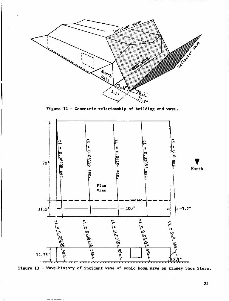
Figure 12 - Geometric relationship of building and wave.
c1 rc c1 rr c1 rr
4
12.75' Y
r / / j / /-- / //, - ~//,,,/,,,//,////~//,~// / / / / / //
Figure 13 - Wave-history of incident wave of sonic boom wave on Kinney Shoe Store.
25

ATir
**ir
Time interval between bow and tail waves = 0.135 sec. Apo = overpressure = 1.65 psf = 0.0078 sec. I> bow reflected wave
bow incident
c time
tail reflected wave
tail incident wave
c time
At wall height = 6.0'
c time
At ground level
Figure 14 - Sonic boom pressure histories on the Kinney Shoe Store west wall.
26

DIFFRACTION AND REFLECTION OF SONIC BOOM WAVES BY CORNERS AND WALLS
I
The preceeding sect ion presented a method f o r predict ing the wave h i s t o r i e s of w a l l s which were h i t d i r e c t l y by a sonic boom wave. the "shadow" or which receive the ref lected e f f e c t s of nearby w a l l s o r corners, a fu r the r development i s required. I n pa r t i cu la r , the broken window i n the Kinney Shoe Store w a s both i n the shadow region and beneath an overhanging canopy. In the t i m e i n t e rva l between bow and t a i l shock, there w a s s u f f i c i e n t time f o r near ly twenty wave ref lec t ions between the ground and the overhanging roof. It i s obviously hopeless t o attempt t o pred ic t the pressure h i s to ry on the window without re l iance on a computer programmed t o include both wave input and proper boundary conditions,
For wal ls which are i n
Such a technique w i l l be out l ined below,
Sonic booms are considered t o a c t as acoust ic waves, o r plane weak pulses , s ince they are very weak shock waves. I n Reference 2 , the d i f f r ac t ion and re- f l e c t i o n of an incident plane pulse by wedges and corners has been t r ea t ed and e x p l i c i t , closed-form expressions have been obtained i n terms of elementary
A so lu t ion i s sought t o the acoustic wave equation i n a two-dimensional
I geometry.
Wave
X
P -Po p = =
1 0
( 1) P ' l 1
pxx + pyy = 2 p t t
i n the region Q 10 - 2n-+ p = o Y I where 8 i s the polar angle,
8 = arcTan Y/X, I Figure 15 - Incident wave on a wedge.
By def in i t i on , the half-planes a t 0 = 5 Q form a wedge o r corner, depending on whether Q is less o r grea te r than 90°.
27

The solut ion t o be considered w i l l have jump d i scon t inu i t i e s on c e r t a i n moving surfaces representing the shock wave, say r(X,Y) = ct . s a t i s f y the eiconal equation.
We require t h a t r
(2)
This implies t h a t the surface can be constructed by Huygen's p r inc ip l e , t h a t i t moves with velocity c along i t s normal, and t h a t i t i s r e f l ec t ed from the wall i n accordance t o the s i m p l e r e f l ec t ion l a w . A fu r the r assumption i s t h a t the re f lec ted discontinuity value i s twice the incident , following the r i g i d w a l l assumption & = 0.
an
The orthogonal t r a j e c t o r i e s of a family of d i scont inui ty surfaces S ( t ) are
Denote the area of the tube a t s t r a igh t l ines ca l led rays. The set of rays through a small closed curve on a discont inui ty surface S(to) i s ca l led a "tube".
S ( t ) by dSo and the area of the tube a t S ( t ) by dS.
t i n u i t i e s a t S( to) and S ( t ) are po and p, respect ively.
t r y , the magnitudes of the d iscont inui t ies must vary inversely as
Also, the pressure discon- 0
Then, f o r plane geome-
dS+O
Equation (3) permits p t o be computed from po on the same ray, once the discon-
t i n u i t y surfaces are known.
Referring t o Figure 15, the ray d i r ec t ion i s normal t o the d iscont inui ty plane and is pos i t ive i n the d i r ec t ion of motion. d i rec t ion and the X axis i s $, and i t i s always pos i t ive .
The angle between the ray
It follows from (2) t h a t a plane discont inui ty sur face moves p a r a l l e l t o i t s e l f with veloci ty c along i t s normal and from (3) tha t a pressure jump, pC1, across the wave f ront does not change. This s i t u a t i o n continues u n t i l the wave reaches the wedge. Then re f lec ted and d i f f r ac t ed d iscont inui ty surfaces may or ig ina te . These surfaces can be obtained from the configuration a t the in s t an t of contact. Then the incident plane progresses p a r a l l e l t o i t s e l f , and one ( fo r $ > 0) o r t w o (for $ < 4) re f lec ted plane d iscont inui ty surfaces plus a c i r c u l a r cy l indr ica l surface with the wedge as i ts axis are produced: Figures 16 and 17 . See
The pressure jump across the o r ig ina l plane is unchanged and the jump across the ref lected plane wave i s equal to- t h a t of the inc ident , making p=2. The pressure jump across the cy l ind r i ca l wave is zero, however, s ince a l l rays reaching i t come from the axis where dSo = 0 . Thus, p is not discontinuous
across the cylinder. The value of p everywhere outs ide the cyl inder is known (e i the r 0, 1, o r 2 ) . Since & = 0 on the wedge and p is continuous across the
c i r c u l a r arc, the values on the boundary are known. From these values i t i s possible t o determine the p values within the cylinder.
an
28

The wave pa t t e rns are se l f - s imi la r with respect t o t i m e , and so can be presented i n X / c t and P/ct coordinates, as i n Figures 16 and are t o be sought i n s ide the c i r c l e along r a d i a l l i n e s f r o m the or ig in . of spec ia l po lar coordinates i n W t space w i l l be used f o r t h i s so lu t ion , which follows the method of Keller and Blank; Reference 2 .
1 7 . Solutions A set
r = [ c ~ -(XZ + YZ)] 4 s = ct / r
e = T ~ Y / X
(4)
The boundary of the circle is given by r = 0 and s = -, and equation (1) becomes
Incident wave
/-\ Reflected \
x \ wave, Y
/ \ / Y / P = 0 I \- / \ \ /
X c t -
- Y c t
Figure 16 - Diagra 0
/ m of a plane wave in te rsec t ing a wedge;
ne re f l ec t ed wave.(# > 9)
c t
29

Figure 17 - Diagram of a plane wave intersecting a wedge; Two reflected waves.($ 6 )
In accordance with the assumption of similarity, p = p(s, e). Then (5) becomes:
r 1
L i s
s-1 t2 Zf we set P 3
Pee = O
then (6) becomes LaPlace's equation:
30

The so lu t ion t o (8) may be writ ten i n the form
p = Im f(Z)
i e where f(Z) is an ana ly t i c function of the complex var iab le Z = p e
Introducing R = (X2 + Y2)’, we have from (4) and (7)
. (9)
i e - x + i Y ct+ (c~t2-R2)’ Z = p e -
R (10) p = ct + (&L$) L,
The cone R < ct i s thus mapped i n t o the uni t circle p 5 1. The problem has been reduced t o Fbt of f inding the function ana ly t ic i n an appropriate s ec to r of t he u n i t c i r c l e with prescribed imaginary par t on the boundary.
The values of p on the boundary of the circle i n Figure 16, f o r $<I$, are:
p = O o n p = 1 , @ < 8 < @ + a - - p = l o n p = l , $ + a < e < 2 ~ - $ - b
p = 2 on p = 2, 2a - @ - b 5 0 - < 2n - @
* = O on 0 - - < p < 1, 8 = @ and 0 = 2r - I$ ae For Figure 17, where JI < 4, the boundary values are:
p = 2 o n p = l , @ < e < @ + a - - p = 1 on p = 1, (0 + a < 8 < 2n - I# - b
p = 2 on P = 1, 2n - @ - b 5 0 ~ 2 a - @
* = 0 on o - - < p < I, e = 4 and e = 2n - I# aa
I n order t o solve f o r p, the ex te r io r of the wedge w i l l be mapped from the Z plane onto the upper ha l f of the W plane by the transformation
w = pleiw = (ze -io) A n where X = -
2(n -0)
Thus, p = p A , W = X (e-$) = X (0-n) + . (12) The c i r c u l a r sec tor i n which p is t o be determined becomes a semicircle i n
the W-plane with * = 0 on the diameter ( in to which the s ides of the wedge
transform). By the r e f l ec t ion p r inc ip l e w e may extend p i n t o the whole plane, and obtain a boundary value problem i n the unit circle; See Figures 18 and 19.
ae
The next s t ep is the determination of a harmonic function p with piecewise constant boundary values. The solut ion of the problem may be obtained as the
31 I

sum of solutions each of which takes on a specified constant value on one arc of the circle and is zero on all other arcs.
and p = c on the arc W~LWLW~ and p = 0 elsewhere.
the form (Reference 2 ) :
Suppose W2> W1 with W2!-w1 ~ 2 7 1 ,
Then p can be shown to take
p = o -iXa p = 2 e -i (n-Ab)
Figure 18 - Complex plane wedge/shock representation.($ > g)
Figure 19 - Complex plane wedge/shock representation.($ < 4)

And i n terms of
.. 1 L A L
p = - arcTan w2-w1 1 (l+P12)COs\-)- 2 2PlC0S
TI
The arctangent is taken i n t h e i n t e r v a l between 0 and TI.
be wr i t t en e x p l i c i t l y as follows: The so lu t ions may then
Case 2 , 0 5 J, 5 4
Application t o sonic boom incident t o a building. - Using equation (14) o r (E), one can compute the pressure d i s t r ibu t ion i n a c i r c u l a r arc of radius ct surrounding a comer of a s t ruc tu re struck by a sonic boomwave. def ines the region i n which the wave is d i f f r ac t ed and r e f l ec t ed due t o the presence of t he corner. Let :
The circle
t = t i m e elapsed s ince the wave h i t the corner of the s t ruc ture . H = height of the s t ruc tu re .
Then, i f c t > H , the c i r c u l a r sec tor has reached the ground and has been r e f l ec t ed ; the previous formulae cannot be applied d i r ec t ly . associated with incident bow and ta i l waves with an expansion region between them ( the "N" wave). waves. b r a i c sum of the pressure d i s t r ibu t ions of each of these elements: bow wave ( incident and r e f l e c t e d ) , expansion wave region, and t a i l wave ( incident and re- f l ec t ed ) . I n Figures20through23, a few mult iple r e f l ec t ed disturbance regions of a sonic boom wave pas t a r i g h t angled comer are shown. For t h i s case, +=O, 4 = b. So equation (15) i s t o be used t o compute the pressure d i s t r i b u t i o n of a d i f f r ac t ed incident w a v e a t point (XI ,Y1) i n the neighborhood of the corner.
Pressure d i s t r i b u t i o n a t any time i s a function of the height of the point above ground l e v e l and the geometry of t he re f lec ted dis turbance regions.
Sonic boom waves are always
In addi t ion, both bow and t a i l waves have ground-reflected The pressure d i s t r ibu t ion of a sonic boom can be computed as the alge-
2 2 In the i n t e r v a l 0 - < c t - <$I + Y1 , p(X1,Yl) = 0, 1, or 2; t he value
depends on t he wave locat ion a t the t i m e .
33

I n the i n t e r v a l d v l <ct <7/X: - + (2H-Y1)2 , (Figure 20) ' p(X1,Y1)
can be computed from the equation f o r disturbance C1 only.
sure disturbance a t p due t o C is computed using
8 = arcTan ( l/X1) - I$, and R = 7/;(:..: and p =
I n the interval7/X: + (2H-Y1)2< c t <2H + d w ,
Thus, pl, the pres-
1' Y
P1
(see Figure 21) '
p(X Y ) can be computed by t r e a t i n g the point as a f fec ted by C and i t s ground
r e f l ec t ed disturbance C C is t r ea t ed as a mirror image of C 1' 1 1
1: 2 ' 2
Ground Level
p (X Y ) is the pressure a t the boundary of the region C which may be 2b 1' 1 2'
3 '
.) y1
Figure 20 - Wave re f l ec t ion by a bui lding; Phase I
34
~
Figure 21 - Wave r e f l e c t i o n by a bui lding; Phase I1
~
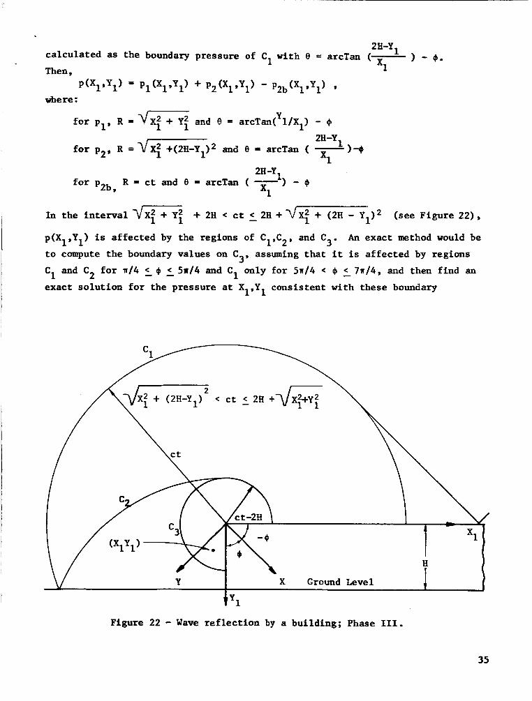
2H-Yl ca lcu la ted as the boundary pressure of C1 with 8 = arcTan ( x. 1 - 0.
i Then
where :
2Ii-Y for p2, R =vq +(2H-Y1)2 and 9 = arcTan ( - 1-4
=1 2H-Y,
f o r p R = c t and 8 = arcTan ( -') - 4 2b , =1
In t he i n t e r v a l
p(X1,Yl) is af fec ted by the regions of C1,C2, and C
t o compute the boundary values on C assuming t h a t it is af fec ted by regions 3' C1 and C2 f o r w/4 2 4 5 5 n / 4 and C1 only fo r 5n/4 < @ - < 7w/4, and then find an
exact so lu t ion f o r the pressure a t X19Y1 consistent with these boundary
+ 2H < c t < 2H + 7/X: + (2H - Yl)2 (see Figure 22),
An exact method would be
I
I -
3'
t y1
Figure 22 - Wave r e f l e c t i o n by a building; Phase 111.
35
condi t ions. This method i s very d i f f i c u l t , i f indeed poss ib le , because i t re- qui res s a t i s fy ing var iab le boundary conditions involving complex expressions. It i s therefore suggested t h a t an easier, and perhaps f a i r l y accurate , method is t o assume tha t the influence of region C on the point i s due t o a peak normal 3 shock of s t rength equal t o the d i f fe rence of p2 (O,ct-2H) and
3: at $I = 5n/4. Then p(X ,Y ) is the sum of the pressures due t o C ,C2 , and C 1 1 p(xl ,yl) = p l ( x l , y l ) + p2(X1Py1) - Pzb(xl,yl) + P 2 ( 0 d x x i - p2(0,ct-2H)
Y where fo r p
for p
R = d e and 8 = arcTan( l / X l ) - 4
R =v- and 8 = arcTan ( - ) - 4
1’
2 ’
2H-Y1
x1 211-y~
x1 f o r p R = c t and 8 = arcTan ( - ) - 4 2b’
Figure 23 - Wave re f l ec t ion by a bui lding; Phase IV
36

f o r p 2 ( 0 , d R ) , R = 2H +$R and e = a
f o r p2(0,ct-2H), R = c t and 0 = a
I n the interval?jXi + (2H-Y1l2+ 2H < c t - < 4H + d R (see Figure 23),
p(X ,Y ) is computed as affected by regions C C C th ree t r ea t ed as i n the previous example.
ground r e f l e c t i o n of C
and CqY with the f i r s t
can be considered as the I I I' 2 ' 3'
4 For p4, C
3' By ~ s e nf a digi ta l , c-mputer, t h i s precess car, be sxtmded to l a rge =umbers
of r e f l ec t ions and the pressure d i s t r ibu t ions predicted as functions of time f o r given w a l l geometrics and wave incidence angles. Note however, t h i s development appl ies t o two-dimensional cases only, so t h a t the wave must be para l le l t o the edges of the w a l l s .
Figure 24 depicts the window on the north w a l l of the Rinney Shoe Store, under the roof overhang, t h a t was broken during the seventh f l i g h t of a F-101 a i r c r a f t on May 17, 1964. The sonic boom wave f o r the pa r t i cu la r conditions is shown as determined i n the previous analysis. For the two-dimensional ana lys i s t o consider the comer e f f e c t s , the wave w a s assumed p a r a l l e l t o the w e s t w a l l , neglect ing the 3.2" t h a t w a s estimated i n the previous analysis . As shown i n Figures 24 t o 26, the incident and re f lec ted waves (considering only the bow as a s t e p input a t present) are d i f f r ac t ed by the roof overhang and r e f l ec t ed by the ground and roof overhang. The sonic boom wave i s considered as a two-dimen- s iona l wave and the e f f e c t s of t he north edge of t he roof overhang and south- extending w e s t wall are neglected. The wave-history f o r the window and f o r some of the poin ts on the north-west corner were estimated using the analysis developed above, considering the e f f ec t s of the re f lec ted disturbance regions on the r i g i d w a l l s ( the ground and the roof overhang). The X and Y axes w e r e se-
lec ted a s shown i n Figure 24. For t h i s pa r t i cu la r geometry, 4 = 0 and JI = 19.9". Subs t i tu t ing these values i n equation (14),
1 1
A = - = - a 1 2a-24 2
1 I
- (1-p) cos %($-a)
(l+p) Sin %(#I-=) - 2p2 Sin %@-IT)
- (1-1 cos %(@-IT)
5 p = l - - arcTan a
L (I*) Sin %(*) - 2p Sin %@-a)
1 + - arcTan II
Simplifying equation (16),
p = 1 - - arcTan 3 1
(1-p) Sin $/2
cos $/2 - 2p+ cos e/2
(i+p) COS +/2 + 2 p % COS e/2 ( l - p ) Sin $/2
[ ll
1 + - arcTan 1
37

A computer method w a s developed f o r the wave h i s t o r y a t any poin t xl, Y
coordinate s y s t e m shown i n Figures 24 - condition a t which the incident wave of t he sonic boom has reached the o r i g i n of the chosen coordinate axes (west edge of t he roof overhang). t r i bu t ion due t o the subject sonic boom w a s computed a t various poin ts on the north w a l l of the Kinney Shoe Store as i n sketch below.
i n the
The t i m e t = 0 corresponds t o t h e
The pressure d is -
1 26.
West- c 4 1 H = 12.75' (,F
- 24.5 e 6 3.6' Ground leve l
North w a l l of the Kinney Shoe Store (view from i n t e r i o r )
In Figure 27, the pressure d i s t r i b u t i o n a t points A through F are p lo t t ed f o r a s t e p input wave (pi = 0.5, pr 0 . 5 ) .
A sonic boom ord inar i ly w i l l have the shape of an N-wave. The t i m e i n t e r - v a l , A t , between the bow and t a i l waves of the sonic boom t h a t caused the broken window has been estimated from re la ted test da t a t o be 0.135 seconds. An N-wave can be t reated as two s t rong shocks of equal s t rength (pi = pr = % A p ) and a
series of weak expansion waves between them. An N-wave of s t rength pi = 0.5 and
pr = 0.5 a t bow and t a i l waves separated by 0.135 seconds w a s assumed. Then 135
small expansion waves were assumed of s t rength p
by a t i m e i n t e rva l of 0.001 seconds. pressure a t any t i m e t
s t ep waves, e f f e c t i v e a t t ha t t i m e .
0
= -1.0/135 = pr, each separated i A computer program w a s wr i t t en and the
determined from the sum of the pressures due t o a l l t he i
About 15 minutes w e r e required t o obta in the pressure h i s to ry of each poin t from t
pressure h i s to r i e s of the points A through F are p lo t ted . The dot ted l i n e s rep- resent the input wave i f there were no corner o r overhang e f f e c t s .
= 0 t o ti = 0.16 seconds on an I B M 7040 computer. In Figure 28, the i
Since the da ta ind ica tes t h a t Ap f o r the subjec t f l i g h t w a s about 1.65 ps f , 0
mult ipl icat ion of the poin ts on Figure 28 by 1.65 w i l l give the estimated pres- sure h is tory on the window exter ior .
38

- Ln
N 4
?
- 1 -
X
u-l al &
n & 0 4 I, al U C 4
E 0 I, u
5 L 0 G
-1 ..
r) 1 'p
G r)
w al 3 0) & 0 u cn al 0 w
u C 0 r u-l
0 P
W 0
k
3 s 0
I
U N
39
o[ c (d
aJ -E
w 0 0 Pi
I
l-4 c
Q L 0 U m
h PI C c
rn C t4 Q U U (d a
Q c (d
r 1 M 4 F

a 3
\ \ \ \ \ \ \ L
n & 0 4 & al U c d
3 & cu .c U & 0 C
M C 4 0 a ru
5 4 > W
al b 0 U rn
r( M aJ 5 w 0 d
5 b 0 E
E 0 rn __ C & al U u a a
U
Q 4
H
I
\o N
x
41

0 9 "! I 4 0
"! rl
0 9 "! d 0
"! rl
0 9 v! 4 0
"f rl
al ).I a tn
r( 0 a 3 0 a E 4 3 X .d VJ
U a h ).I 0 U VJ 4 c aJ &
tn tn al & a
a
al ).I a
42
4s

\o Ti
VI d
U rl
m Ti
hl
Tf
d rl . 0 -f
o\
9
9
?
?
9
9
?
9
9
co
I-
\o
m
U
m
N
d
0 "! 9 "! I4 d 0
4Z0
0 ?
o\
9
9
9
9
a0
I-
\o
VI 9
9
9
9
9
U
m
h(
rl
0 "! 9 "! d d 0
d"
\o d
In rl
U d
m rl . cv rl
d
Ti
0 rl
0
o\
9
9 " B
9'
?
9
9
9
?
. L)
03aJ - -4
\o
In
U
m
hi
rl
9
0 9 "! r( 0
"! d
dZO
. 5 aJ 5 3 d 0
u I h N PI & 3 bo ri F
43

9 d
v! 0 "! 9 "! rl rl 0 0
1 I
44
9 v! P 1
r(
0 v! 0
v! 9 rl d
al l-i 1 m m aJ t.4 a l-i aJ $ U
VI 0
c a h 0 w m U C d 0 a
d 3 X d m U (d
h l-i 0 U m
.r( s
1 M .d F 4

t
9
9
9
9
ul
e
m
N 0 . rl
9
9 rl
"! 0 9 "! rl 0 0
"1 4
I I
\o d . VI d
U t
t cr)
N T-l . rl 4 . 0 Ti
9
9 " t
9'
9
9
9
9
9
o\
. U
mal - *+
\o
VI
U
m
N
4 0
"! 9 v! 0 v! 9 " rl 0 P " I
rn
E 3 rl U E 0 U
I
Q) N
01 & 1 M
45
L

9 ? P I
I+
0 9 ? d 0
? 4
46

CONCLUDING REMARKS
The three methods presented f o r calculat ing the time-f-passage of an inc i - dent wave and the t i m e i n t e rva l between incident and re f lec ted waves f o r a w a l l facing the wave give almost i den t i ca l r e su l t s f o r s m a l l o f f s e t dis tances (10,000 f e e t or less) from the f l i g h t track. The differences i n r e s u l t s are g rea t e s t a t low Mach numbers and large o f f s e t distances (up t o 70,000 f e e t ) . The conical wave ana lys i s (Method I) gives the poorest accuracy. The method (Method 111) which assumes an atmosphere with a l i nea r va r i a t ion of acoust ic ve loc i ty with a l t i t u d e up t o the tropopause and which uses the simplifying assumption of constant ray angle project ion i n the v e r t i c a l plane normal t o the f l i g h t path is considered t o be the m o s t p r ac t i ca l method.
The method presented and computer method developed fo r determining the pressure-time h i s t o r i e s a t the four corner po in ts and mid-point pos i t ion of the broken window locat ion under the roof overhang of the w a l l i n the "shadow" pro- duced no ind ica t ion of any abnormal or unusual shock wave ac t ing on t h i s window area. However, the f a c t t ha t t h i s window did apparently break as a r e s u l t of the p a r t i c u l a r f l i g h t considered suggests the need fo r continuing study and inves t iga t ion i n t h i s area.
It i s concluded that development of confidence i n these or other ana ly t i ca l methods and the determination of the va l id i ty of various assumptions as t o both atmospheric conditions and f l i g h t da ta values w i l l require s p e c i f i c f i e l d tests designed and conducted for t h i s purpose.
Andrews Associates, Inc. 1330 Classen Building
Oklahoma C i t y , Oklahoma, June 20, 1966
REFERENCES
1. Lansing, Donald L.: Application of Acoustic Theory t o Predict ion of Sonic Boom Ground Pa t te rns from Maneuvering Aircraf t . NASA TN D-1860, 1964.
2. Reller, J. B. and Blank, A.: Diffract ion and Reflection of Pulses by Wedges and Corners. no. 1, June 1951.
Communication on Pure and Applied Mathematics, ser. 4,
3. Luneberg, R. K.: Mathematical Theory of Optics. University of Cal i forn ia Press, 1964.
4. Keller, J. B.: Mechanics of Continuous Media. New York University Lectures, 1949-50.
47