of electromagnetic interference effects on ... - auto safety
TRANSCRIPT

I I DOT HS-801 737
INVESTIGATION OF ELECTROMAGNETIC INTERFERENCE EFFECTS ON MOTOR VEHICLE ELECTRONIC CONTROL AND SAFETY DEVICES
I
Contract No. DOT- HS-4-00918 October 1975 Final Report
PREPARED FOR:
U.S. DEPARTMENT OF TRANSPORTATIOW
NATIONAL HIGHWAY TRAFFIC SAFETY AOMlNlSTRATlON
WASHllffTON, OX. 20590
I -. Do*lmam is availabla to the public through the National Technical Information Service. sprinlfidd Virginia 22161

1. Report No.
DOT HS -801 7 3 7
3. Recipient's C o t a 6 g No. 2. Government A c c e s s i m No.
I6 AbrtracI
This report describes the resu l t s of a study to invest igate , ident i fy , and analyze the potential problems of electromagnetic interference from a l l sources ( in te rna l an external to the vehicle) that may cause malfunction of motor vehicle e lectronic control and electronical ly actuated safety devices.
This program accomplishes an analysis of inter- and intra-vehicle energy t ransfer a n coupling by computer simulation, u t i l i z ing DOD developed modeling techniques tha t hav been employed for a wide range of EMC/EMI design and evaluation support problems. These applications have included a i r c r a f t , spacecraft, and advanced surface ships.
P computerized c i r c u i t analysis model adapted from the 18M Electronic Circui t Analysis Program (ECAP) i s used to assess susceptabili ty of representative types o f electronic components and subsystems typical ly used i n automotive electronic applications.
A preliminary EM environmental source f i l e i s provided based on a l i t e r a t u r e search of vehicular internal noise sources and worst case external electromagnetic f i e l d descriptions.
4. Tit?* ond Subtitle
Effects on Motq Vehicle Electronic Control Investigation of El ectromgnetic Interference
and Safety Devices
7. A u r h c d r ) R.H. Espeland, L.A. Jacobsen, I .-. F . 1 Morrisan, Jr.
q. P e i b r m i n g Orgonizotion Name and Address
U.S. Dept. of Commerce i3ff i ce of Tel ecommunica ti ons
20 ; idation t e s t plans and preliminary EMC guidelines f o r automotive electronics a re ? u n a r i zed.
5 . R ~ p o r t 0.1. October 1975 -
6. Performing O~gonimt ion Code
8. Performing Oc*anixo+ion Report No.
- 10. Work Unif No, ( T R A I S )
- 1 1 . Confr-ct or Grant No .
17. Words Electromagnetic interference, automotive electronics , automotive safety, EMC guidelines, noise immunity
I n s t . fo r Telecommunication Sciences
U.S. Department of Transportation National Highway Traffic Safety Administrntion
Boulder, Colorado 80302 1 2 Spenrorbng Agency Name ond Address
400 Seventh Street 8.W. Washington D.C. 20590
Document i s avai lable to the public through the National Technical Infomation Service,Springfield ?Virginia 22161
DOT-HS-4-00918 13. T y p e o f Repert and Persod C0vcr.d
Final Report o f Period June 10, 1974 June 1 , 1975
14 Sponsorlng Agency Coda
19. Security ClessiI. ( o f this report)
Uncjlassified 1
x). Sccurily CIo f. (of this p w d ) 21. No. of Pq.s 22. Price
Unclassified

TABLE OF CONTENTS
LIST OF ILLUSTRATIOh’S
LIST OF TABLES
AESTRACT
PAGE
vi
xi
1
1. INTRODUCTION 2
9 2. TECHNICAL DISCUSSION OF ENVIRONMENTAL SOURCE FILES
9
’ 2.1.1 The Primary Power Supply System 10
2.1 Internal Sources
2.1.2 Normal Loads and Impedances
2.1.3 Cranking Engine
2.1.4 Voltage Regulation
2.1.5 Transients
2.1.6 Other Noise Sources
’ 2.1.7 Ignition Noise
2.1.8 Electrical and Accessory Noise
2.1.9 Temperature Considerations
2.2 External Sources
2.2.1 Broadcast Signals
2.2.2 Radar
2.2.3 Mobile Radio
2.2.4 Power Transmission Lines
2.2.5 Industrial Sources ,
12
15
15
17
10
19
21
22
25
26
29
32
33
35
iii

2.2.6 Flourescent Lamps 36
2.2.7 Automotive Ignition Noise 38
2.28 Lightning 41
3. TECHNICAL DISCUSSION OF COUPLING MODELS 43
3.1 Wire-to-Wire Compatibility Analysis Program (WTWCAP) 43
3.1.1 The Basic Model 44
3.1.2 An Example Run 48
3.2 General Coupling Characteristics 53
3.2.1 External Lights 55
3.2.2 Inductive Loads 60
3.2.3 Lights and Inductive Loads 69
4 . TECHNICAL DISCUSSION OF RECEPTOR ANALYSIS MODELS
77
4.1 Device Characteristics 79
4.1.1 Digital Logic and Gate Functions 79
4.1.2 Operational Amplifiers 93
4.1.3 Driving and Buffer Circuits 96
4.1.4 Sensors and Transducers 99
4.2 Model Development 101
4.2.1 ECAP 101
4.2.2 ECAP Modifications and Limita- 106 tions
4.2.3 Bipolar Transistor Model 115
4.2.4 Five Region CMOS Model 119
5 . SUBSYSTEM SUSCEPTIBILITY 130
’ 5.1 Device Sensitivities’and Noise 130 Immunity
iv
-
5.2 Circuit Sensitivities
5.2.1 Four Transistor Flip-Flop
5.2.2 CMOS Flip-Flop
5.2.3 Darlington Amplifier
5.3.4 Operational Amplifier
6. TEST PROGRAM
6.1 Introduction
6.2 Validation Rationale
6.3 Test Plans
7. CONCLUSIONS AND GUIDELINES
7.1 Introduction
0 7.2 Internal Source Control
7.3 Power and Signal Transmission
7.4 Circuit Selection and Design
7.5 Receptor Packaging and Placement
7.6 Operational Control Techniques
8. ACKNOWLEDGEMENTS
9. REFERENCES
10. ADDITIONAL READING
APPENDIX A: DIPOLAR MODEL STABILITY
APPENDIX 3: ECAP EXPANSION SOFTWARE
134
134
141
164
167
174
174
17 4
176
187
187
189
191
193
195
196
197
199
202
207
212
n
V

LIST OF ILLUSTRATIONS
Automotive Electronic Devices FlGURE 1.1 1.2 2.1 2.2
2.3 2.4 2.5 2.6 2.7 2.8 2.9 2.10 2.11 2.12
2.13
2.14
2.15 2.16
2.17
2.18 2.19 2.20 3.1
3.2 3.3
PAGE 4
Automotive EM1 Research 7 Primary Power System Block Diagram 11 Primary Power Supply Characteristics 13 Identification Typical Battery Discharge Curve 14 Battery Impedance vs. Frequency 14
Alternator Field Decay Transient Voltage 20 Load Dump Transient Voltage Envelope 20
Typical Powering Line with no Battery
Cogging Effect 16
21 Power Line Electrical Noise 23 High Frequency Noise Envelope 23 Alternator Output vs. Speed and Temperature 25 Ground-Wave Field Strength for 50 RW AM 27 Stat ions Relationship Between Fie13 Strength, Effective 28 Radiated Power, and Distance from Antenna Relationship Between Free-Space Field Strength 29 and Power Density Representative Transmission Line Noise 35 R-F Stabilized Arc Welder and Plastic Welder 37 Noise R-F Stabilized Arc Welder, Wood-Heater and 37 plastic Preheater Radiated Flourescent Lamp Noise 39 Automotive Ignition Noise 40 Calculated Electric Field Intensity 42
Parameter Circuit Model Two-Wire Coupling with Single PI Lumped 45
Two PI Circuit Model 45 Transfer Funciton €or 1, 2, 3 PI Lumped 46 Parameter Circuit Models
vi
I(
INVESTIGATION OF ELECTROMAGNETIC INTERFERENCE EFFECTS
ON
MOTOR VEHICLE ELECTRONIC CONTROL AND SAFETY DEVICES
R. H. Espeland, L. A. Jacobsen,
L. R. Teters, and E. L. Morrison, Jr.* f -
ABSTRACT
This report describes the results of a study to investigate, identify, and analyze the potential problems of electromagnetic interference from all sources (internal and external to the vehicle) that may.cause malfunction of motor vehicle electronic control and electronically actuated safety devices.
This program accomplishes an analysis of inter- and intra- vehicle energy transfer and coupling by computer simulation, utilizing DoD developed modeling techniques that have been employed for a wide range of EMC/EMI design and evaluation support problems. These applications have included aircraft, spacecraft, and advanced surface ships.
Electronic Circuit Analysis Program (ECAP) is used to assess sus- ceptability of representative types of electronic components and subsystems typically used in automotive electronic applications.
on a literature search of vehicular internal noise sources and worst case external electromagnetic field descriptions.
Vaf$dation test plans and preliminary EMC guidelines for automotiQe electronics are summarized.
Key Wordsi Electromagnetie interference, automotive electronics,
A computerized circuit analysis model adapted from the IBM
A preliminare EM environmental source file is provided based
* E.L automotive safety, EMC guidepes, noise immunity.
L *The authors are with the Institute for Telecommunication Sciences, Office of Telecommunications, U. S. Department of Commerce, Boulder, Colorado 80302
1

--
1. INTRODUCTION
The number and performance characteristics of commercial and pleasure (passenger) road vehicles have increased significantly over the previous two decades. Regulatory actions have evolved during this period, primarily at the state government level, resulting from higher vehicle speeds and greater population densities. State imposed vehicle inspection procedures attempt to insure a minimum safety and control capability for vehicles licensed to operate on public roadways. Inspection standards and acceptance criteria are different for automobiles and small cqmmercial vehicles (e.g., panel and pickup tsucks) than for the larger buses and multiple-axle trucks.
With increased vehicle performance, recently imposed emission regulations, and the current fuel economy emphasis, the potential for utilization of electronic control techniques for various energy management and safety functions is well recognized. The former application (control) includes fuel distribution and engine carburetion and exhaust operations. The latter (safety) includes radar and acceleration-controlled braking, speed control, passenger restraint and safety device actuation (e.g., air bags and door locks), light control and internal power management. Implied functional operations include analog and digital computa- tions and control, with energy conversion devices used for sensing and actuation.
These electronic systems must be integrated into vehicles where control requirements have been satisfied by mechanical and hydraulic devices. With these devices, the vehicle environment considerations have primarily concerned such characteristics as tbmperature, moisture, and vibration. With increased sophistica- tion in control and safety areas, electronic devices present cost-effective alternatives to the competing ihechanical, hydrau- r
lic, and pneumatic systems. Electronic systems used could
2
t -
. . c
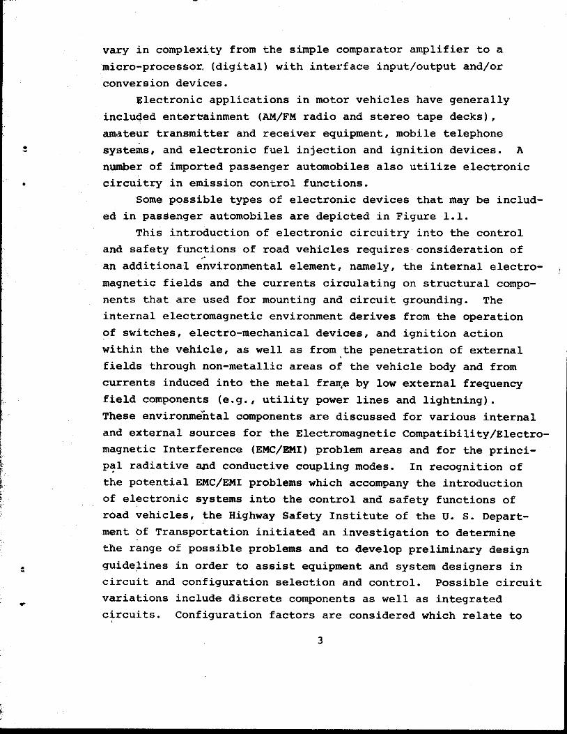
vary in complexity from the simple comparator amplifier to a micro-processor. (digital) with interface input/output and/or conversion devices.
Electronic applications in motor vehicles have generally included entereainment (AM/FM radio and stereo tape decks), amateur transmitter and receiver equipment, mobile telephone systems, and electronic fuel injection and ignition devices. A
number of imported passenger automobiles also utilize electronic circuitry in emission control functions.
Some possible types of electronic devices that may be includ- ed in passenger automobiles are depicted in Figure 1.1.
This introduction of electronic circuitry into the control and safety functions of road vehicles requires consideration of an additional environmental element, namely, the internal electro- magnetic fields and the currents circulating on structural compo- nents that are used for mounting and circuit grounding. The internal electromagnetic environment derives from the operation of switches, electro-mechanical devices, and ignition action within the vehicle, as well as from the penetration of external fields through non-metallic areas of the vehicle body and from currents induced into the metal fraqe by low external frequency field components (e.g., utility power lines and lightning). These environmektal components are discussed for various internal and external sources for the Electromagnetic Compatibility/Electro- magnetic Interference (EMC/BMI) problem areas and for the princi- pal radiative and conductive coupling modes. In recognition of the potential EMC/EMI problems which accompany the introduction of electronic systems into the control and safety functions of road vehicles, the Highway Safety Institute of the U. S. Depart- ment Of Transportation initiated an investigation to determine the range of possible problems and to develop preliminary design guidelines in order to assist equipment and system designers in circuit and configuration selection and control. Possible circuit variations include discrete components as well as integrated circuits. Configuration factors are considered which relate to
,.
3

m r- ul rl
4
/”
physical arrangement, shielding, and grounding. AS indicated previously, these circuit applications include analog and digital coniputational and control (e.g., switching, amplifications, comparison) functions.
This investigation included a determination of the general character of the intervehicle electromagnetic (EM) environment from various internal and external sources. In this investiga- tion, the following topics were studied: device energy coupling magnitudes based upon estimates of the effective apertures for cabling and devices, transfer magnitudes for cabling and grounding elements, and degradation characteristics for basic analog and digital functional elements (with t\e undesired signal or noise components coupled through the signal, control, and power Connec- ti@s for the test circuits).
//Tor device or system designers, a parametric investigation was performed to determine the sensitivities in relation to such characteristics as cable length and bundle arrangement, termina- tton impedances, circuit configuration and operational mode, and vehicle functional state (e.g., starting, parked, moving, and day-night and related variations). Device and system design decisions also considered shielding, grounding and waveform specifications. I The EMC/EMI guidelines have advisory impact on design, and, therefore, must indicate constraints on the physical arrangement and placement of vehicle cabling and on the mounting, grounding, and connector integrity aspects involved in maintenance and measurements required to insure compliance with specifications. These specifications dictate the type of measurements and the amplitude or waveform parameters that define the undesired signal Qr noise spectrum constraints, coupling magnitudes, and shielding and grounding effectiveness required.
This investigation relied primarily upon simulation and modeling techniques in order to define the ranges of coupling and degradation for the conductive and radiative transfer and circuit responses.
In order to provide maximum utility
Such procedures are considered necessary in an initial
5

- 7 --
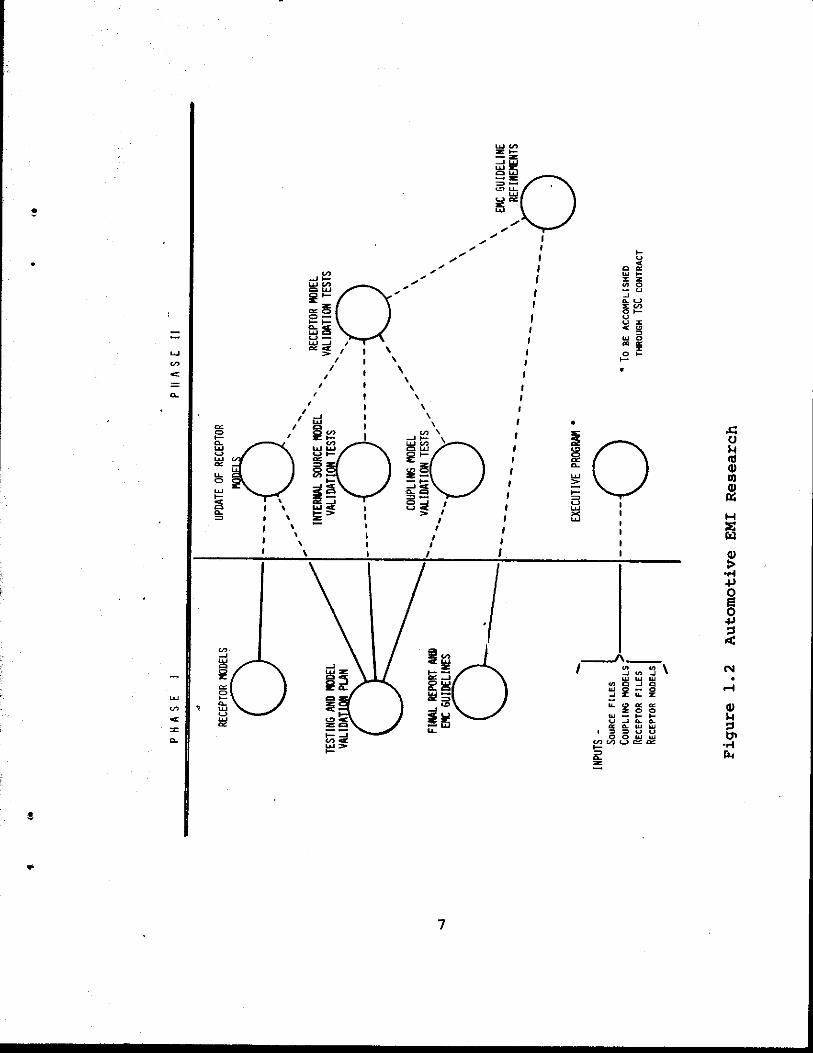
investigative effort in order to indicate papametric and configur- ation sensitivities, and to provide a basis for planning subse- quent measurements which are designed to validate the simulation predictions and to quantify the coupling and degradation parametek variances. The vehicle configuration variations (device location and cable bundles), the source device arrangement and operational made differences, and the different analog and digital circuits available are typical justifications for employing simulation and modeling for sensitivity analysis, measurement planning, and as the basis for the initial design and application guidelines relative to coupling and degradation characteristics. The general time-phase relationships between modeling and measurement are diagrammed in Figure 1.2. For this EMC/EMT program, the modeling effort was completed in Phase I, and the validation and noise source measurements, will be accomplished in Phase 11. Such a relationship between modeling and measurement activities has proven invaluable to many military system development and perfor- mance, or measurement specification quantification requirements. A coordinated measurement program with performance-related data and identifiable characteristic relationships is to be expected. These relationships concern the functional connection between coupling, circuit parameters, and degradation. This includ'es problems relating to the intra-system (vehicle or site) EMC/EMI analysis for aircraft, space vehicles, sites involving co-loca electronic equipments (computers, radars, communications, elec optical devices), and naval ships. Modeling developments and supporting validation measurements in these problem areas over the previous 10-15 year period have produced t f simulation tech- nology with an established credibility.
i
For this program, models have been utilized which treat con- ductive and radiative energy transfer, bonding and grounding resources, and circuit performance. These have been employed extensively in the EM intra-systems analysis areas preViOUSly cited, thus assuring credibility for the parametric analysis per- formed here. These models are described in Sections 3 and 4 .
6
?
i
c
0 0
I I I I I I
I I 1
I I I
I I I
I I I I
I I I I I I I
"0 W 2
I-
3 I % I
I I
b 'L
7

AS mentioned previously, the model data will guide the measure- ment operational modes and the form of data analysis necessary. This procedure follows the proven experience of previous EMC design support or performance evaluation programs.
In addition to the model prediction-validation relationship and source file refinement, the organization of the coupling and degradation models into an integrated program under the control of a set of executive routines is indicated in Figure 1.2. This integrated system will provide the Department af Trans&?wtation wi’th a “user-oriented” simulation capability to support future design or test specification development and evaluation of ad- vanced vehicle control or computational syste concepts or con- figurations. Upon completion of Phase 11, this integrated model- ing system would include the updated source models, coupling model parameters, and degradation descriptors derived from the measurement tasks. Previous experience organizing such integrated model systems in relation to file structures, retrieval methods, and model configuration will be applicable to this task.
Subsequent sections of this report discuss the energy cou- pling and transfer models, and the circuit model simulation procedures utilized for this investigation. The validation and model-updating measurements will be accomplished during Phase ‘l3. The preliminary guidelines regard the EMC/EMI aspects of circuif- ry design, selection and placement, and the cable bundling and routing within a vehicle. These guidelines also indicate grou ing, bonding, and shielding specifications in relation to inter- ference sources, spectral content, circuit type (discrete ccmrps- nent or integrated circuits), and functional applicatian.
8
6
thbugh the non-differential output noise amplitudes are . 4 V and - 1 5 V respectively. Thus the differential output noise is smaller than the single ended output noise by more than 60 dB. These numbers will vary considerably as the matching in beta of the transistor pairs vary. In this example the input betas were matched exactly, while those of the output stage were purposely
P
! I I
1 .s mismatched by about 1.5%.
I operational amplifier has high inherent power supply noise inunun- ity. Also since induced pick-up noise tends to have high posi- tive correlation, this amplifier will eliminate most of this type noise due to its high common-mode rejection. The main noise problem will result from single ended input noise or asymmetric input noise.
I Preliminary ECAP analysis has shown that this particular
,
17 3

6. TEST PROGRAM
6.1 Introduction The program reported herein has concerned an analysis of
energy transfer and coupling phenomena within a road vehicle, and the susceptibility of various types of analog and digital cir- cuitry to impulsive and continuous forms of interference compon- ents. This analysis has been based on computer modeling of wiring harness segments and the various types of receptor cir- cuits, with the vehicle operational mode constraining the inter- harness energy coupling (e.g., switch, light, and device condi- tion in relation to vehicle operation) parameters. Cable ter- mination impedances and the effective apertul-es for internal sources and receptors have obvious model sensitivities. These computer model exercises have provided a range of parametric and configuration dependent transfer, coupling, and degradation definitions which allow the development of preliminary EMC re- lated design and applications guide-lines for road vehicle electronic equipments.
This modeling effort has also employed a wide band impulsive form of stimuli to maximize the resolution o f the transfer and coupling analysis. ment and vehicle designers also requires specification of the relative spectral density characteristics of the conductive and radiative components of actual internal sources (e.g., ignition, electromechanical devices, switches). A measurement program to develop such a source file is included in the Phase I1 effort. Subsequent paragraphs discuss these two measurement efforts.
6 . 2 Validation Rationale
Utilization of the EMC guidelines by equip-
This research and analysis effort (Automotive EM1 RESEARCH - PHASE I) produced a preliminary EM environment file (internal and external) germane to a typical motor vehicle, a computer model for analyzing the signal coupling properties within the vehicle,
.
174

atld a computer model to evaluate the sensitivities and suscepti- bilities of electronic circuits and subsystems.
The internal environment files were developed from reports and studies conducted primarily by groups in the automotive and electronics industries. The coupling functions for the wiring harness and grounding elements were derived through the wire-to- wire coupling module of the “Intrasystem Electromagnetic Com- patibility Analysis Program (IEMCAP) as originally developed for the U.S. Air Force, and the receptor analysis capability was evolved from the IBM “ELECTRONIC CIRCUIT ANALYSIS PROGRAM” (ECAP) .
Although computer modeling in EMC/EMI analysis and evalua- tion applications has received wide acceptance and confidence for nearly a decade, the necessity of validating model predictions must always be recognized. This model-measurement relationship provides parameter uncertainty resolution and establishes con- fidence in simulator predictions. In general, simulation is a principal vehicle in designing measurement programs through identification of parameter or configuration sensitivities indi- cating what - factors are to be measured, guidance regarding how - the measurements are to be accomplished, and the data analysis and interpretation methods. This model-measurement relationship is a consideration when parameter or configuration variations are such as to cause an unacceptable confidence level in model data.
’ The models employed for this program have attained a high degree of credibility because of the extensive application to aircraft and space vehicle EMCJEMI problems. Because of the large possible variances in cable characteristics and arrange- ments and the effectiveness of structural and metal case shield- ing in commercial road vehicles, a validation and parameter .definition measurement program is required. The demonstration is also important to establish confidence in a community that is not so oriented toward modeling as those concerned with military EMC problems. This is also important in the evolving utilization of simulation techniques for vehicle and equipment life cycle man- agement support (design, testing, maintenance phases).
175
.-
6 . 3 Test Plans A significant part of the Phase 11-AutomotTive EM1 Research
effort will be devoted to the source measuremenk and validation test program. The specific test categories defined are: 1) internal source (environment) measurement, 2 ) signal coupling and transfer model validation test, and 3 ) the receptor model valida- f
these tests fall into two areas: 1) those to be preformed pri- f
tion and subsystem susceptibility tests. For planning purposes
marily on a test vehicle and 2 ) those to be preformed in a laboratory or laboratory test situation. The test philosophy, facilities, types of measurements, and methodology of these areas will be discussed in the following paragraph’s.
ON-VEHICLE TESTS Internal source characteristics must generally be measured
while operated on a conventional vehicle with aSl interconnec- tions. The filtering and shielding factors forded by struc- tural components and device interconnections (including switch actions) must be reflected in the source emission definition. Isolated device meaeurements are useful but must be modified when utilized for environment specification by the effects imposed by the normal modes of employment. In the vehicle, both normal and abnormal operating conditions can be create& which generate the signals to be measured under normal loading, filtering, and coupling conditions. loading, primary electrical power line loading, open and closed switches, and component failures can be varied to determine the environmental effects.
Also sdch parameters as engine speed, motor
A list of typical internal automotive devices that can produce interfering signals is given below:
1. ignition systems, 2. generator and regulator systems, 3 . switches, 4. motors,
176

5. soleniods and relays, 6. flashers, 7. sensors (electronic, magnetic), 8. static dischargers, 9. entertainment systems, 10. mobile transmitters (telephone, amateur), 11. automotive radar, 12. air-conditioning clutches, 13. garage door openers (transmitters).
This list suggests that three basic classes of interfering signals could be generated by the various sources: periodic related to engine speed, periodic related to motors, etc., and aperiodic related to the random actuation of switches, solenoids, etc. It is generally known that the potential interfering sig- nals can range from a few volts to well over lOOV amplitude. In addition, some of the aperiodic signals appearing on the power supply lines have a polarity opposite to that of normal supply voltage.
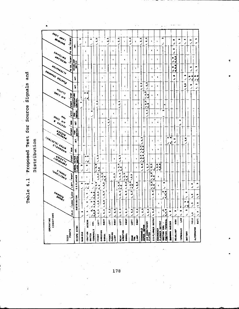
Equipment to be used for these vehicle measurements will include an oscilloscope with both high-impedance voltage probes and clamp-on current probes, wideband radiation probes, and a speCrrum analyzer. signals will be determined, as well as the spectral content of the background noise. A display of proposed tests to measure the source signals and their distribution is shown in Table 6.1. This table is in matrix form showing the vehicle operating con- ditions, the test points, and the test code. An explanation of the test code and intended equipments is on the second page. use of additional test points will be considered as the results of these tests may dictate.
Radiation measurements will include discrete frequency and energy densities in the regions of the front grill, rear bumper and axle, passenger and driver areas, and primary vehicle body gaps (hood-fender, hood-cowl).
The amplitude and duration of pulse-type
The
177
_-_-
a c m ln .-I 'aj E tn
.
178

a s m rl m c F -4 m o V & 7 0 m & 0 w +* ll,
m E-,
rl
W
0) -, rl
€4 2
.
a, a 0 0 m m (5 0 N rl
a, a 0 0 (0
m P 0 N rl
PI PI
X X
I
2
m a' !A
4J m e am O h V L l m 7
U
4
8
m P o w NV) r ld
P I P I
x x
. .
. .
A A I
A J
A V V v \
m V .rl s m a o m
m l a 0 -4 m m m
c m m o
179

LABORATORY TEST These tests are concerned with the cited parametric updating
for model enhancement and validation of predicted coupling magni- tudes. This phase concerns sensitivity tests of components and subsystems and a number of coupling measurements on the wiring
controlled experimental conditions thus enhancing the ability to
harness. The advantages of a laboratory environment are the t.
isolate specific stimuli and transfer mechanisms in the absence * of normal vehicle background noise. A controlled environment with adequate diagnostic instrumentation allows close correlation WLWI model exercises. Receptor devices to be included in these tests include discrete component and integrated circuit function- al elements of the type modelled, and various electronic safety and control ‘subsystems that could be individually procured. functional circuits, as previously indicated in Section 4 , are listed:
The
1. gates (AND, OR), 2 . flip-flops, 3. counters (Binary and Decade), 4 . decoders, 5. encoders, 6. drivers and buffers, I. adders, 8 . shift registers, 9. core storage modules, 10. operational amplifier.
t r
Commercial modules will be utilized, functionally similar to the circuitry included in the model exercises.
Safety and control circuitry will be tested as available. Since these devices include varying combinations of the previous functional circuitry, correlation in E&~C characteristics (consider- . ing configuration dependencies) will be demonstrated. Candidate control elements are listed: .
1. ignition systems, 2 . radar braking,
18 0
,r
3 .
4 .
5.
6. 7. 8. 9.
10.
speed control, voltage regulation, anti-lock braking, electronic fuel injection, passive restraint air bags, seat belt interlock, headlight dimmer, exhaust emission control.
These lists suggest the choice of subsystems and component fhnctions that can be included in the test plans. Availability and diversity will govern which devices will be actually tested. These will be specified in the test plans being completed for Phase 11.
The facilities for testing discrete devices, integrated circuits, and electronic subsystems developed and operated by the Air Force Weapons Laboratory (AFWL) Electronics Division at Kirtland, AFB New Mexico will be used to perform the circuit and subsystem tests.
EMP susceptibility of components and subsystems, the facilities and the measurements techniques, analysis procedures, and data handling methods are directly applicable to this EMC program. As cited previously, the impulse stimulus is uniquely compatible with that employed for the computer coupling and circuitry models.
Even though the emphasis at AFWL has been measurement of the
The AEWL Direct Drive LabQratory will be utilized for the
"Direct Drive" refers to hard coupling of the interference harness coupling and circuit upset testing.
signal into the circuit/subsystsre. For these tests, the impulse source would be coupled into a cable harness with appropriate termination switches and load, and to the power, control, and ground lines or terminals of the indicated circuitry modules.
Direct drive includes four types of test:
(1) Direct Injection to determine damage or upset thresholds at subsystem interfaces.
181

(2) Component Testing to obtain failure or response parameters for individual components.
( 3 ) Nondestructive Pulse Tests to detect spurious coupling paths.
( 4 ) Continous Wave (CW) Measurements to define transfer functions and input and output impedances.
Any or all of these tests may be employed as part of an itqJTulse upset or damage assessment. Their relative importance will depend on the individual system. All direct drive tests are characterized by tight coupling between the environment source and the test specimen. This coupling may be rssi’stive, inductive, or capacitive and coupler requirements are a significant test design consideration. Since the coupling is efficienct, the environment source tends to be relatively ineprpensive (compared to the environment source for system level testirrlg).
of equipment required for subsystem testing. This includes environment sources, transient instrumentation, and data proces- sing. Laboratory are categorized as follows:
The AFWL Direct Drive Laboratory includes the complete range
The major equipment items available in the Direct Drive
(1) The Automatic Test System (ATA) Mhich provides a range of diagnostic instrumentation and pulse and dc sources under computer control.
( 2 ) The Environment Generators which.provide a variety of pulse and continuous wave environ- ments with a range of pulse shapes, frequencies, and output levels. Three types of generators are available: the Linear Amplilfier , the Damped Sinusoid Pulse Set (DSPS), and the Rectangular Pulse System.
182

d
c
The Distribution System which interconnects the test specimen, the environment generator, and the ATS.
The Automatic Network Analyzers which provide wide band frequency domain analysis of com- ponents and circuits under computer control.
The Data Reduction System which is used for processing both diagnostic and transient response data.
Other Test Equipment, including oscilloscopes, oscillators, impedance bridges, etc.
This equipment can be employed either separately or in v,nrious combinations to meet the test objectives. One part- icularly useful combination consists of the ATS, the Distribution System, and the Linear Amplifier. This combination is referred to as the Programmable Universal Direct Drive (PUDD). The PUDD provides for complete automation of subsystem direct injection testing, as is depicted in Figure 6.1. The Distribution System provides sufficient interface capability so that the ATS computer can control the operation of the test subsystem and the operation of a number of auxiliary equipmmt items.
circuit subsystems with wideband pulse and discrete frequency sources. Sequential testing of a harness with switched termina- tions, and circuit modules with appropriate shielding and cable connectors will be accomplished. These tests would be conducted in AFWL facilities, and possibly limited circuit and functional level measurements in NBS TEM cells.
Radiation testing involves illumination of harness and the
. Diagnostic measurements for the wideband tests would
* include pulse-time waveforms, wave front flatness, and the direct and reflected component ratios. Instrumentation for this
183

184

requirement is available at both facilities. uration is important relative to sensor and data transfer cable arrangement and connections to the test device to remove second- ary current effects. fied as elements of standard test methodology for control of test cell arrangements and methods of testing to assure minimal experi- mental bias.
Experiment config-
Procedures have been developed and certi-
Measurements in the radiative test phase will include inter-wire coupling within a harness with mode related termina- tion switching, and circuit and subsystem functional degradation. Dsta to be recorded for analysis for the harness coupling include induced time waveforms and in some cases a direct spectral dis- play in relation to termination conditions, and circuit module responses as related to the magnitude and form of the interfer- ence signal and mode of coupling.
and/or conductive sources will be generally measured from the general functional considerations listed:
Circuit module operation with interference from radiative
a. Flip-flop circuit - Turnover delays, failures to operate, false operation, output noise level.
b. Gates - Failures to operate, response delays, false operation, output noise level and form.
c. Adders - Sum errors in relation to word rates. d. Counters - Sum errors in relation to input
rates. e. Shift registers.- Bit or word position errors
f. Storage Modules - Failure to accept or retain bits or words, unintended readout, induced destructive repd-out, output noise level and form.
as function of; ccnimand rate.
g. Operational Amplifier - Output noise level and . form, transfer function error.
I For the digital and pulse operated circuits and modules, the amplitude of tbe impulse and continuous mode interference, and
185

the phase differences between impulse interference and control and signal pulses must be varied to develop multi-variant res- ponse descriptors. For these functions the amplitude and time phase of the interference component, and the entry mode must be included in the degradation (noise immunity plot). description.
data may also be recorded to assist in understanding of the indicated functional performance characteristics. Waveform recordings at specific internal points present unique problems, however, in experimental bias potential; and must therefore be carefully considered in the instrumentation and analysis planning for data validation.
L With discrete component circuits and modules, diagnostic
186

7 . CONCLUSIONS AND GUIDELINES *
7.1 Introduction The electromagnetic compatibility considerations for road
' vehicle electronic systems concern the design, fabrication, and a maintenance phases of the life cycle. All phases have nearly
equal importance if desired or required operability criteria are * to be assured. Success in the EMC aspects of vehicle operations
ultimately requires coherent management procedures. cedures should detail the simulation and measurement requirements and the techniques that have some commonality in methodology and data support files. Regulations and supporting technical and o2erational documentation which are "user oriented" should also accompany these EMC analysis and measurement elements. The sim- ulation system should provide a modularized set of radiative and conductive coupling models (field-to-wire, wire-to-wire, bond re- sonance), numerical circuit and subsystem scoring (S/Ii; S/I. I ... ) model files, internal and external source files, sets of empirically based aperture penetration discriptors, as well as an executive program to manage and control the computational, data Ease organization and operation, inter model data exchange, and 1/0 operations. Programs (computational and control routines) in tape or card form, selected files, and the Technical and User Manual documentation could be available at a central computer or furnished to a designer or manufacturer for use at a separate computer facility. This type of simulation capability assures commonality in procedures and equipment characteristic files for all design and manufacturing requirements. It allows a direct comparison in data output from independent exercises with a common system configuration. This mode of operation represents significant cost savings for industry subsystem and vehicle manu- facturers, and for agencies of DOT with EMC and equipment certi- fication re'sponsibilities.
validation, as well as the development of vehicle device and
These pro-
c
0
The measurement procedures should accommodate computer model
la7
equipment emissions for the Source File updating, and instru- mcintation techniques useable by maintenance groups associated with sales and service organizations. Basic measurement re- quirements concern emission and coupled spectral densities (radiation and conduction components) and time wqveforms for the various internal aperiodic energy functions. Instrumentation components would include connectors and impedance converters for direct coupling to wiring and circuit test points, wideband radiation sensors with impedance transformers, signal converters and conditioning filters, spectral density extraction (comb filters or FFT micro processor), and recording and display de- vices. For maintenance and service facility applications, the inter connections, control mechanisms, and display devices must operate with procedures not too dissimilar from current diagnos- tic instruments. Utilization and data interpretation procedures must impose a minimal special training and education requirement for service personnel.
These simulation and measurement applicatiohs will be detailed in Phase I1 of this EMC/EMI program and incorporated into the revised guidelines. As mentioned, these technical support elements are important to effective management and quality assurance.
The preliminary EMC/EMI guidelines summarized in this section relate to the harness arrangements, shielding methods, circuit types, and operational modes. These guidelines result from the simulation exercises and application reviews of the E'hase I program, and will, as indicated previou&ly, be refined through the validation and source measurements of the Phase I1 effort. These initial guidelines address basic methods for controlling interference through specification of source emission and wiring arrangements, shielding practice, and recognition of the immunity properties of various types of analog and digital circuits that would be employed in vehicle electronic systems. Subsequent paragraphs discuss these control areas.
188

7 .2 Internal Source Control
devices and subsystems within a vehicle is problem oriented (in application) since the cost effectiveness of such a solution depends upon the specific character of the devices and their method of employment. The guidelines for source control should, however, generally follow the experience of the aircraft industry in establishing sets of procedures for control of the basic waveform generated, the utilization of filtering devices in the conductive leads, and shielding techniques to reduce the radia- tive component to an acceptable level. As cited previously, cost effective considerations prevent a direct extrapolation of spec- ifications applicable to the aircraft industry into the road vehicle arena.
The control of both radiative and conductive emissions from
a
Typical of the problems are the measurements of transients that can occur on the vehicle power wires. During starting Sction, for example, the 12V power bus may be subjected to volt- ages that reduce to approximately 5v with peaks extending to - + 2 4 volts. Transients where high inductive loads may be trans- ferred momentarily on or off the power line may result in magni- tudes of 75 to 130 volts. These pulse signals will vary in width from the millisecond range to several microsecond range. Pre- vious measurements of RF noise components has demonstrated ampli- tudes of + 20V over the frequeney range of 100 kHz to 7 MHz. These components generally originate from switching transients on top of rotating device noises, as well as spurious emissions from the ignition system. If a vehicle has a radio telephone system with improper grounding, the RF noise could originate from such a source. This is particularly true where the improper grounding also includes a corroded joint. This "diode" action has been demonstrated on shipboard as the "rusty bolt" effect. The non- linear praperties generate a wide bandwidth of emissions when illuminated by a discrete frequency.
-
e
External sources to which the vehicle may be exposed include commercial broadcast stations with a possible maximum exposure of
&
189

lOV/m to 70V/m, and radar installations of the type employed at airports that may illuminate a vehicle with fields of 1000 V/m. Lightning transient fields can well be of the "same integrated magnitude as that cited for an airport radar. Tllese broadcast and radar signal amplitudes are obviously pessimistic occurring when the radiators are in close proximity to a roadway.
noise components includes parameter selection anq design to minimize extraneous components in the generated waveform, the employment of filtering devices to reduce extraneous components to an acceptable level, and proper shielding to prevent the unintentional escape of spurious spectral ccmponents. The spec- ific application of any technique is obviously governed by cost and the usage of the source device. As an example of the latter, passive filters employed in a high current line present serious component cost and packaging implications. Impedance and power loss considerations here would probably dictate other techniques of source waveform control and shielding technique. For a low- current source, however, passive filtering represents generally a very cost effective spurious component eliminator. The R, L, and c components can be small with very low cost as contrasted to the fabrication expense of shields and the component expense associated with coaxial cables and special purpose connectors.
Waveform control within the output circuitry of any func-
il As indicated previously, the control of internally generated
.
tional device would involve functions such as time gating or limiting, these utilizing active circuitlly with the attendant expense.
the employment of proper grounding techniques. ,Resonances in the grounding bonding straps, an& the provision for clean joints with the frame or grounding buses are important in radiative coupling and assuring shielding effectiveness. Resonances are of obvious importance where a high number spurious or harmonic components of
provided by a ground or bond strap, and is therefore a potential
Undesired components can also be removed or suppressed by
*
a wideband pulse is present. A significant aperture can be D
1
190
pr&lem for DTL and TTL logic and high gain operational ampli- fiers. For the latter, the wideband interative operations have the highest susceptibility. 7 . 3 Power and Signal Transmission
Current wiring practices for road vehicles involve a harness Configuration. that connects instrument and control panel areas to the engine compartment and forward lighting, the transmission controls, and the rear lights. This harness generally appears as a Y and is fastened to the inner frame along of the length of the car and passes into the passenger compartment near the steering column. This harness generally comprises only bundles of insu- lated wires which provide virtually no protection from wire-to- wire transient transfer. Noises induced onto wiring in the engine compartment or large switching transients associated with, for example, the horn relay or turn signal operation can also couple through the bundle with little impedance. Because these bundles connect generally to lights or other low impedance loads, one end is terminated relatively close to ground level. With electronic circuits connected to such a wiring arrangement, how- ever, the impedance relationships would not be advantageous from the viewpoint of wire-to-wire energy coupling. These wires are also unshielded, and except for those regions where they are mounted close to the longitudinal structure, limited shielding from radiation is available. This radiation problem can be particularly severe because of me length of the wires and the consequent large effective aperture. For electronic circuits with a significant input impedance, therefore, severe problems are to be expected from the radiative environment internal to the car.
*
S
Consideration of cable cornfiguration should therefore in- clude separation of power and signal distribution bundles.
f Coaxial cables may be necessary for many of the signal lines
IL types of receptors connected. Wide bandwidth digital type signals present particular problems because of the limited
where, for example, FET on time-controlled digital logic are the
191

utility for standard filtering schemes. Time gating is useful, but for interference having high periodicity rates, the potential for significant improvement by time gating is very limited. Coaxial cables are therefore almost mandatory for pulse-infor- mation-transfer applications. Where a CW carrier with AM or FM modulation is employed in a control function, spectral filtering techniques provide significant improvements in noise immunity because of the limited bandwidth of the receptor device. Modula- tion components are significantly less vulnerable than pulse waveforms. For continuous modulation formats, further noise immunity is accrued through coherent detection which generally adds little in cost to circuit development or fabrication.
impact in the wiring system for a road vehicle. This is obviously most sensitive with passenger automobiles. Commercial vehicles would be much less effected because of the higher total cost.
Assuming cost factors could be reconciled, the future employment of multiplexed data bus configurations provides significant EMC/EEMI enhancement capabilities for multifunctional vehicular control. A single shielded wire could be routed throughout the vehicle with signal sources and receptors coupled through appropriate multiplex-demultiplex equipments. frequency-multiplexing schemes would be employed with only minor Aifferences in immunity for the road vehicle type of environment. These data transfer techniques have found a signfficant applica- tion in aircraft syseems where a high degsee of noise immunity was necessary and cost-space considerations prevented the employ- ment of bundles of coaxial cables. With integrated circuit technology the multiplex-demultiplex cost considerations are nearly negligible. be fabricated to tolerate the temperature and other physical environment of a road vehicle, the life time of.this circuitry should readily exceed that of other automobile accessories, assuming normal usage.
Coaxial cables admittedly represent a significant cost
Time or
Since such integrated circuitry can readily
192

The previously cited EM1 reduction procedure of separating signal and power cabling represents a recognizable disadvantage in fabrication and maintenance of a road vehicle. These cables cannot always have large physical separation because of the close proximities that will be necessary in such areas as the engine compartment, instrument panel, and the connections to transmis- sion control and sensor devices. 7.4 Circuit Selection and Design
The previous chapters of this report presented immunity and degradation data for a variety of integrated and discrete compon- ent analog and digital functional circuitry. Basic elements were modeled and functional modules were also evaluated, particularly for families of logic. Salient characteristics of the opera- tional considerations of this logic include operating levels, noise immunity, noise generation, fan-out/ fan-in, and power dissipation.
For logic element, the analysis of the presented data indicates that for noise pulses exceeding 200-300 ns, the pro- pagation delay and rise-times and fall-times are important. Evidence also indicates that the sensitivity to power supply voltages is affected by the noise on the signal and control linea. This is_ particularly aggravated when the noise on the signal and power lines are correlated. (See Sections 4 and 5).
The operational amplifier has a limited vulnerability for noise on the power supply lines. With a balanced input circuit, uncorrelated noise on both inputs is amplified as an unbalance signal. Uncorrelated noise on the positive and negative supply lines is reflected in the output as a vector addition, with transients less than 10% of the supply voltage. Spectral modifi- cation is directly related to the bandwidth limiting properties of the transfer function in the operational feedback circuit. The direct input connection is particularly sensitive because of the high impedance. In normal operation this circuit point would always be protected by shielding and the connections through the feedback and driving operational components. Noise on the ground
193
line presents more effective coupling than the same magnitudes on the power lines because of the additive connections in the input balanced amplifier. Operational amplifier utilization therefore requires- shielding of the amplifier device, short grounding lines connected to a common bus, or a single chassis ldcation.
The Darlington amplifier requires similar considerations in the shielding and input line protection. Noise on the power lines in the range of 5% to 15% supply voltage presents little problem in operation of the circuit. Analog circuitry generally present much less problem in signal filtering than digital elements because of the reduced signal bandwidth. The major exception would be a relative comparison between'a high speed repetitive analog element and lower bit rate serial digital systems. Repetitive analog computers have found limited applica- tion in motor vehicles because of the sensitivity to power supply regulation and with the higher stability operational amplifiers a
problem in noise immunity relative to low to intermediate digital computation elements. Advantages in maintenance, cost, and functional effeciency also accrue to digital computation.
The increased utilization of micro-processors also presents significant advantages in the digital area in respect to noise immunity. These devices can be colocated with sen~ors, thus affording reduced susceptibility because of impedance and signal funn conversions. Difficulties with micro-prm'essors in the motor vehicle application relate to the maintenance of proper grounds over extended operating per,iods and through service cycles. A tendency will probably emerge towards single element o,r distributed computation in only two or three interval models in order to mimimize service costs and complqxity.
Shielding, grounding, and cable protection will therefore be the principal EMC/ EM1 prdblems. DTL, ECL, and CMOS logic were indicated in this report (Section 5). With the forthcoming test program these sensitivities will be verified and the subsequent guidelines (Phase 11) will indi- cate a range of environmental and parametric sensitivities for
The relative comparisons of TTL,
194
. L
various pulse control and digital computation applications. Supply voltage sensitivities for the noise immunity data were presented. At the higher supply levels (% 15V) CMOS and ECL have significant advantages relative to other logic types. For the latter, the current drive and low input impedance affords apprec- iable protection to wire-wire induced noise. 7 . 5 Receptor Packaging and Placement
rihielding and physical configuration for mounting subsystems and electronic circuits within a motor vehicle, and the placement of these circuit elements within a vehicle relative to structure and noise sources. Integrated circuits will, for cost and mainten- ance reasons find an accelerating application for digital and analog functional requirements. Packaging considerations rela- tive to volume are also important. Maintenance of IC circuitry would therefore be relagated to module replacement. Discrete component circuit boards will find application for the next few years with maintenance in the eschelon category, but at the local service facilities, complete replacement will still be necessary. ?raining for service personnel and diagnostic equipment dictate this replacement philosophy.
ry be assembled in a shielded container. Power transistors that must be exposed to free air flaw can follow the same procedures .IS currently employed for ignition control and light control devices where the shielded cwer and radiator fins protrude external to the box and therefore afford necessary heat transfer. This consideration is of importance primarily for power converter circuitry. .(<
shielded container. These organized in modular structure within a second shielded container connected into shielded signal lines and power and control lines with passive filtering devices as necessary could be utilized in any area of the motor vehicle.
This section discusses considerations relative to the
Packaging considerations require that all electronic circuit-
Integrated circuit elements are generally assembled in a
195
.e

Grounding should be accomplished through single-point or star techniques, where a common connect:.on through a bonding strap or a mounting lug is provided. This single point grounding removes the possibility of circulating currents in the frame from causing interfering effects within the circuitry. The grounding strap should be shorter than 5 cm with a net resistivity of less than .01 ohm per cm to minimize potential for resonances where high frequencies (> 1OOMHz) fields may be present. The only potential sources within a commercial road vehicle that hatre components within this range are the ignition and power solenoids and relays. The ignition problem results principally from badly worn points and defective by-pass capacitor. This data has been verified by previous measurements of the ignition spectral densities from
various types of automobiles, with allowances for different ignition conditions. Noisy power relays, such as the type that operate headlights and horns, can also produce this range of
1 . 6 Operational Control Techniques
tional procedures of electronic systems in accordance with mode of operation of the vehicle. For example, the speed controller could be deactivated when the car is not moving. I f , under conditions imposed by a nonmoving vehicle, the speed controller had a serious EM1 problem when the car is not moving, deactiva- tion of the circuit may be the least costly approach to solving the interference problem. Such a circumstance could exist with certain classes of electronic ignition control because of pulsing characteristics of power transistors and the inductive load of the ignition coil. An overlaping pulse rise and decay character- istic which may have radiative additive cornpone& could exist at higher englne speeds. The solution with electronic techniques would involve perhaps some expensive shielding procedures, but with deactivation of the speed controller, a significant cost savings in EM1 assurance would be evident. This type of EM1
solution must receive extremely careful consideration in the
higher frequencies. f
This section concerns exploiting the variation in opera-
P
b
196

*
circuit desigrr because of the direct implication to safety where, for example, in the situation cited, the speed controller was not activated at the speed level required. The cost of assuring reliable operation of the circuit in relation to the automobile mode must be weighted against other more conventional EM1 solutions. This serious problem in assuring a reliable activation signal from one or more sensors relegates this general technique to secondary consideraticn. This discussion is included here, however, for completeness since some success has been achieved in previous systems through deactivation of susceptibility circuits or sensors. Generally in aircraft or military vehicles where such methods have been employed a manual "override" has been provided with warning so that the function is assured of availability even if manually activated. Such procedures are, however, not tractable for commerical passenger vehicles because of driver burden.
8. ACKNOWLEDGEMENTS
The authors wish to express appreciation to Mr. William B. Grant, Mr. Donald H. Layton, and Mr. Bill D. Warner for their valuable contributions and suggestions to this study.
Figure 1.1 reprinted from Electronics, June 21, 1973; Copyright @ McGraw-Hill, Inc . , 1973.
Figures 2.1 through 2.7, P c l l and tables 2.1, 2.2, and 2.4 reprinted with permission, "Copyright @ Society of Automotive Engineers, Inc., 1974, All rigMs reserved."
Figure 2.8 reprinted with permission from IEEE Transaction on Vehicular Technology, May 1974; Copyright @ Institute of Electrical and Electronics Engineers, Inc., 1974. All rights reserved.
Figure 219 and tables 2.3, 2.5, and 2.7 reprinted with permission, "Copyright @ Society of Automotive Engineers, Inc., 1974, All rights reserved."
197
F i g u r e 2.10 and t ab le 2.6 r e p r i n t e d w i t h p e m i s s i o n , "Copy-
r i g h t @ S o c i e t y o f Automotive E n g i n e e r s , I n c . , 1973, A l l
r igh ts r e s e r v e d . " F i g u r e s 2 . 1 2 t h r o u g h 2 . 1 4 r e p r i n t e d w i t h p e r m i s s i o n from
I E E E Spectrum, August 1974: C o p y r i g h t @ and E l e c t r o n i c E n g i n e e r s , Inc . , 1974. A l l r i g h t s reserved.
I n s t i t u t e of E lec t r ica l
I F i g u r e s 2.15 t h r o u g h 2.19 r e p r i n t e d w i t h permission from Don White C o n s u l t a n t s , I n c . , C o p y r i g h t 1972.
V o l u m e 78, N o . 1 8 , page 3525, June 1973; C o p y r i g h t 1973, American C.eophysica1 Union.
F i g u r e s 4 . 1 and 5.1 t h r o u g h 5.4 r e p r i n t e d w i t h p e r m i s s i o n
from IEEE Spectrum, J a n u a r y 1973: C o p y r i g h t @ I n s t i t u t e of Electrical and E l e c t r o n i c s E n g i n e e r s , I n c . , 1973.
from IEEE Spectrum, October 1970; C o p y r i g h t @ i n s t i t u t e of Electr ical and E l e c t r o n i c s E n g i n e e r s , I n c . , 1970.
November 1970; C o p y r i g h t @ I n s t i t u t e of Electr ical and Elec t ronics E n g i n e e r s , Inc . , 1970.
w i t h p e r m i s s i o n from IEEE Spectrum, DecWnber 1970; C o p y r i g h t @ I n s t i t u t e of Electrical and E l e c t r o n i c s E n g i n e e r s , I n c . , 1970.
F i g u r e 2.20 r ep r in t ed from J o u r n a l of Geophys ica l Resea rch *
F i g u r e s 4 .2 t h r o u g h 4 . 4 and 5.5 r e p r i n t e d w i t h p e r m i s s i o n
F i g u r e 4.5 r e p r i n t e d w i t h permission f rom IEEE Spec t rum,
F i g u r e s 4 . 6 t h r o u g h 4.8 and tables 4.1 and 4 . 2 reprinted
F i g u r e s 4.10 and 5.15 r e p r i n t e d w i t h p e m i s s i o n from RCA
S o l i d State D i v i s o n ; C o p y r i g h t @ RCA C o r p o r a t i o n , 1974. F i g u r e s 4 . 1 2 and 4.13 r ep r in t ed by p e r m i s s i o n from 1620
E l e c t r o n i c C i r c u i t A n a l y s i s Program (ECAP). C o p y r i g h t @ 1965 by I n t e r n a t i o n a l B u s i n e s s Machines Corporation.
m
198