electromagnetic interference (emi) - nmea ibex presentation emi.pdf · electromagnetic interference...
TRANSCRIPT

IBEX 2011Speakers:
David Gratton- Martek-Palm Beach, FLJohnny Lindstrom- Westport Shipyard, WA
Electromagnetic Interference (EMI)
Property of the NMEA. Shall not be copied or re-distributed.
Seminar Overview
• EMI Troubleshooting• EMI Prevention with Proper Cabling & Terminations• Lightning Protection• Corrosion• Grounding
Property of the NMEA. Shall not be copied or re-distributed.

Electromagnetic Interference
• Unwanted Periodic Signal/Energy– “One person’s signal is another person’s EMI.”
• Interrupts, Obstructs, Degrades, or Limits Equipment Performance
Property of the NMEA. Shall not be copied or re-distributed.

Electromagnetic Interference
• Radiated Emissions – RF Energy That Reaches Susceptible Equipment via Broadcast
• Conducted Emissions – RF Energy That Reaches Susceptible Equipment via Common Connections
Property of the NMEA. Shall not be copied or re-distributed.

EMI Propagation
• Radiated Emissions –– Signals/Energy that Reaches Susceptible
Equipment via Broadcast– Radiated Power Decreases by Distance Squared
• Conducted Emissions –– Signals/Energy that Reaches Susceptible
Equipment via Common Connections
• Combined Modes –– Signals/Energy that Propagates via Cable
Connections that then Become Signal RadiatorsProperty of the NMEA. Shall not
be copied or re-distributed.

EMI Sources
• AC Units• Alternators• Battery Chargers• Blower fans• Engines• Generators• Inverters• Propeller Shafts• Radars• Wiring Property of the NMEA. Shall not
be copied or re-distributed.

EMI Recipients
• Electronic Compasses• AV Systems• Multifunction Displays• Just about any Electronic Device
Property of the NMEA. Shall not be copied or re-distributed.
Identifying EMI Sources
• Trial-and-Error Process of Elimination– Turn off All Equipment Except for Affected Device– Turn on a Device and Check for Symptoms– Repeat Until Interference Symptoms Return
• Additional Testing May Be Required to Determine If Interference Is Radiated or Conducted
• Interference May Be Radiated from Cables Connected to Interference Source
Property of the NMEA. Shall not be copied or re-distributed.

Avoiding EMI Problems• Layout and Space Planning
– Identify Potential EMI Radiation Sources– Identify Potential EMI Conducted Sources– Avoid Potential Hot Spots
VHFRadio
Auto-pilot
F
RF TransmissionLine
Rudder FeedbackSignal
Parallel cable runs are not desirable
Property of the NMEA. Shall not be copied or re-distributed.

Mitigation Is Application Dependent
Internal HighFrequency
SignalDC PowerSupplyLeads
Signal OutputStage
AC/RFOutput
RF Outputto Antenna(AC Signal
Wave Form)Property of the NMEA. Shall not
be copied or re-distributed.

Mitigation for Unintended Signals
• Objective: Block the Signal– Prevent Signal Transmission on Cables– Prevent Signal Transmission through Enclosure
• Shielded Enclosure with Attached Ground• Input and Output Cables
– Active Filters- usually BandPass or Notch– Ferrites– Best Practice is to attempt to solve problems
within the “offender” rather than the “offended”.
Property of the NMEA. Shall not be copied or re-distributed.

Ferrites as an EMI Suppressor
• Ferrites Composed of Ferrous Oxide and One or More Powdered Metals
• Composite Material Resists Imposed EMI Fields by Suppressing Electron Movement
• Variable Sensitivity to Frequency– Lower Frequencies Pass without Significant Loss– Above Resonant Frequency Signal Becomes
Coupled to Ferrite, Causing a High Impedance
• Increasing Turns Increases Effectiveness
Property of the NMEA. Shall not be copied or re-distributed.

Ferrite Geometry
Property of the NMEA. Shall not be copied or re-distributed.
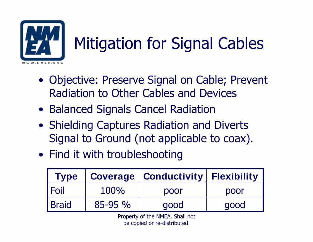
Mitigation for Signal Cables
• Objective: Preserve Signal on Cable; Prevent Radiation to Other Cables and Devices
• Balanced Signals Cancel Radiation• Shielding Captures Radiation and Diverts
Signal to Ground (not applicable to coax).• Find it with troubleshooting
Type Coverage Conductivity FlexibilityFoil 100% poor poorBraid 85-95 % good good
Property of the NMEA. Shall not be copied or re-distributed.

Eliminating Interference: Power cables
• Shielded Cables – Connect One End of Shield to RF Ground
• Grounding – Connect Case to RF Ground– Better to Connect Source’s Case– Less Desirable to Connect Affected Device’s Case
• Filters – Install in Power Leads of offender first• Ferrites – Effective for Conducted and Radiated
Noise
Property of the NMEA. Shall not be copied or re-distributed.

Other Mitigation
• Relocate Cable Runs• Relocate Equipment Displays• Relocate Antennas
– Consider Antenna Radiation Patterns
• Consider Cable Lengths– Avoid Multiples of ¼ Wave Length with power &
data cables– This is not an issue with coax cables
Property of the NMEA. Shall not be copied or re-distributed.
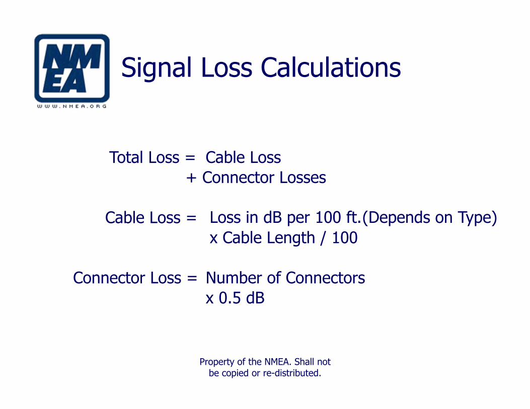
Signal Loss Calculations
Total Loss = Cable Loss + Connector Losses
(Depends on Type)Cable Loss = Loss in dB per 100 ft. x Cable Length / 100
Connector Loss = Number of Connectors x 0.5 dB
Property of the NMEA. Shall not be copied or re-distributed.
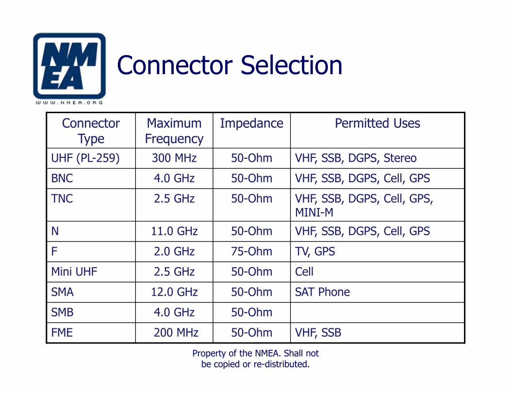
Connector Selection
Connector Type
Maximum Frequency
Impedance Permitted Uses
UHF (PL-259) 300 MHz 50-Ohm VHF, SSB, DGPS, Stereo
BNC 4.0 GHz 50-Ohm VHF, SSB, DGPS, Cell, GPS
TNC 2.5 GHz 50-Ohm VHF, SSB, DGPS, Cell, GPS, MINI-M
N 11.0 GHz 50-Ohm VHF, SSB, DGPS, Cell, GPS
F 2.0 GHz 75-Ohm TV, GPS
Mini UHF 2.5 GHz 50-Ohm Cell
SMA 12.0 GHz 50-Ohm SAT Phone
SMB 4.0 GHz 50-Ohm
FME 200 MHz 50-Ohm VHF, SSB
Property of the NMEA. Shall not be copied or re-distributed.

Cable Bend Radius
Cable Type Bend Radius (inches)
RG58U 2.0RG8X 2.4RG8U 4.5RG213 5.0LMR240 0.75LMR400 5.0
Better to route coax cables using gentle S-curves (green) than tight right-angle turns (yellow) when possible.

Coax Cables
• Attenuation– Transmission Losses (dB per ft.)– Connector Losses (dB)– Impedance Mismatch (Avoidable) 50 Ω - 75 Ω– Also affected by installation
• Cable Length– Minimum Length Necessary (Most systems have no
“tuned” length)
• Equipment Connections– Match Application and Cable Type
• Extensions –beware of the allowed loss

Cable Selection
RG58U RG8X RG8U RG213 LMR240 LMR400
Nominal O.D.
3/16" 1/4" 13/32" 13/32" 1/4" 13/32”
Conductor (AWG)
20 16 13 13 15 9
Impedance(Ohms)
50 50 52 50 50 50
Impedance Match within 2 Ohms
Property of the NMEA. Shall not be copied or re-distributed.

Shielding Connections of Power
• Shields Connected to RF Ground System• Effectiveness Dependent on Low Impedance
to Ground• Best Ground Path for High Frequency EMI
signals is via Copper Foil– #8 AWG Stranded Copper Wire Acceptable
Property of the NMEA. Shall not be copied or re-distributed.

Lightning Strikes- GOOD LUCK!
• Direct Strike – Direct Hit on a Part of the Vessel, Such as an Antenna or Mast.
• Conductive Strike – Strike on a Utility Line and Conducted Aboard Through the AC Power Cord
• Inductive Strike – Nearby Strike Causing a Large Magnetic Field, Which in Turn Induces a Voltage in the Vessel’s Wiring
• There is no sure way to prevent damage from any type of strike.
Refer to ABYC TE-4 — Lightning Protection for more information

Lightning Protection:Two schools of thought
• Conductive and Inductive – Commercially Available Surge Protection Products
• Direct Strikes– Air Terminals Connected to Properly Sized
Conductors, with Relatively Straight Paths to Ground
– Towers Grounded Port and Starboard
Refer to ABYC TE-4 — Lightning Protection for more information
Property of the NMEA. Shall not be copied or re-distributed.

Corrosion
• Electrolysis – Chemical and/or Electrochemical Change Due to Electric Current
• Galvanic Corrosion – Corrosion from Electric Current Flow between Connected but Dissimilar Metals in the Same Electrolyte
Refer to ABYC E-11 — AC & DC Electrical Systems on Boats for more information
Other Corrosion Sources
• Stray Current Corrosion – Electric Current Flow Caused by an Outside Source. (In a Marina).
• Velocity Corrosion – Electric Current Flow Caused by Strong Water Currents
• Selective Corrosion – Electric Current Flow Caused by Areas with Different Composition within the Same Alloy
• Oxygen Starvation – Electric Current Flow Caused by Trapped Electrolytes Making Adjacent Surfaces More Positive to the Remaining Metal Surface
Refer to ABYC E-11 — AC & DC Electrical Systems on Boats for more information

To Bond or Not to BondAge Old Debate!
• Decision Is Vessel Dependent• Bonding Is Fairly Common in the Industry
• Aluminum Is Less Noble Than Almost Everything Else
• Always Isolate From Bonding System And/or Bond by Itself to a Sacrificial Anode Selected Especially for Aluminum
Refer to ABYC E-2 — Cathodic Protection for more information
Property of the NMEA. Shall not be copied or re-distributed.

DC Common Grounding System
• Shorts Stray Potentials to Ground
• May Provide Cathodic Protection
• Usually Main Connection between Vessel and Earth Ground
Refer to ABYC E-11 — AC & DC Electrical Systems on Boats for more information
Property of the NMEA. Shall not be copied or re-distributed.

Grounding System Interconnect
• Objective: Single Point with No Current Flow• Practical: Few Interconnections with No Common Currents
Refer to ABYC E-11 — AC & DC Electrical Systems on Boats for more information

Vessel Grounding Systems
System Type When Required
DC Ground or Negative Reference All Vessels with DC Systems
AC Neutral Reference Vessels with AC Shore Power, Generator, or Inverter Installed
AC Grounding (Safety) Safety
RF Ground Performance Vessels with Electronics Equipment Installed
Single Side Band (SSB) Ground
Performance Vessels with SSB Transceiver Installed
DC Grounding Reference
Lightning Ground Safety
Refer to ABYC E-11 — AC & DC Electrical Systems on Boats for more information
Property of the NMEA. Shall not be copied or re-distributed.