of alternatives for army precision landins i/i … · ad-a174 093 evaluation of alternatives for...
TRANSCRIPT
AD-A174 093 EVALUATION OF ALTERNATIVES FOR ARMY PRECISION LANDINS i/iSYSTEM GROUND GUIDANCEW.) ARINC RESEARCH CORP ANNAPOLISMD C BOYD ET AL JUL 86 2959-ei-2-46
UNCLASSIFEDREAE84-B4Ci7F/G 077NL
mhhhmmmohhhhl

LI
IROCOPY RESOLUTION TEST CHART
or A FAI OF STAF40ANC 1%3 A
ARINC Research Publication 2959-01-2-4106
FINAL REPORT
EVALUATION OF ALTERNATIVES FORARMY PRECISION LANDING SYSTEM:
GROUND GUIDANCE
0') July 19860
U Prepared forU.S. ARMY INFORMATION SYSTEMS COMMAND
I U.S. ARMY AIR TRAFFIC CONTROL ACTIVITYO AITN: ASQ-0D
FORT HUACHUCA. ARIZONA 85613-5380under Contract OAEA1S8-84-C-0 127
Tasks 1-4, CARL Item A008September 1985 - July 1986
- RESEARCH CORPORATION
OTCFILE COPN
't 'A1i'4. (wd ad*b
S11 12 104

UNCLI.SSIFIFD
SECURITY CLASSIFICATION OF THIS PAGE (When Date Entered)
READ INSTRUCTIONSREPORT DOCUMENTATION PAGE BEFORE COMPLETING FORM
1REPORT NUMB3ER ARN esearch 2. iV. ACCE&SION NO. 3.' RECIPIENT'S CATALOG NUMBER
Corp. No. 2959-01-2-4106
4. TITLE (nd Subtitle) 5. TYPE OF REPORT & PERIOD COVEREDEvaluation of Alternatives for Army Precision Research/Study ReportLanding System: Ground Guidance 1 Oct 85 - 31 Jul 86
S. PERFORMING ORG. REPORT NUMBER
No. 2959-01-2-41067. AUTHOR(s) 8. CONTRACT OR GRANT NUMBER(&)
C. BoydJ Gruhler Arinc Research Corporation DAEA 18-84-C-0127R. Lewsen
9. PERFORMING ORGANIZATION NAME AND ADDRESS 10. PROGRAM ELEMENT. PROJECT, TASK
U.S. Army Air Traffic Control Activity AREA & WORK UNIT NUMBERS
ATTN: ASQ-DD 395114A (Program Element)ASQ-DDUSAATCAFort Huachuca, AZ 85613-5380
II. CONTROLLING OFFICE NAME AND ADDRESS 12. REPORT DATE
Development Directorate July 1986
ASQ-DD 13. NUMBER OF PAGES
Fnrt H,, rh,= A7 R -R 5814. MONITORING AGENCY NAME & ADDRESS(II different from Controlllng Office) IS. SECURITY CLASS. (of tht report)
Same as No. 9 above. UnclassifiedI Sa. DC LASSI FI C ATIO0NDOWN G RA I1N G
SCHEDULE
N/A16. DISTRIBUTION STATEMENT (of thle Report)
Report approved for public release; distribution unlimited.
17. DISTRIBUTION STATEMENT (of the ebetrect entered In Block 20, If different from Report)
Same as above.
I$. SUPPLEMENTARY NOTES
DTIC No. DA 304796
19. KEY WORDS (Continue on reveree side If necesary end Identify by block number)
Precision approach radar, global positioning system, forward area arming andrefueling point, forward looking infrared, Doppler Navigation System.Instrument meteorological conditions, night navigation, pulse light approachslope indicator.
20. AST'R ACT (Cehinte m ,everes esd N ne.eeeay amd IdentiII by block number)
\ -This report deals with current and planned aircraft guidance systems as they
apply to Army tactical precision landings in the combat environment. Self-,contained avionics systems and less sophisticated systems have been evaluated.Ground guidance is defined as a means to safely, efficiently, and rapidly aidin the movement of aircraft from their transition point of landing to a final
destination. The study addressed the following four tasks: 1- Review Army Requirements (Ground Guidance) by research of current . w
DD ,r 1473 ITION OFV 6S IS OBSOLETEDO , ., nUNCLASSIFIED
SECURITY CLASSIFICATION OF THIS PA.E (When Des. Entered)

I" SECURITY CLASSIFICATION OF THIS PAGE(lhen Data Entered)
1; 7 documentation and by extensive interviews. -2
dentify alternative systems thvugh specifications and discussions withgovernment and industrial personnel.
Evaluate systems by conducting aviator and engineer evaluations. 44
SIdentify and document best approach for Army use in the tactical
environment.
UNCLASSIFTED
SECURITY CLASSIFICATION OF THIS PAGE(When Data Entered)
- 4a.. '

FINAL REPORT
EVALUATION OF ALTERNATIVES FORARMY PRECISION LANDING SYSTEM:fl GROUND GUIDANCE
July 1986
Prepared for
U.S. Army Information Systems CommuandU.S. Army Air Traffic Control Activity
Attn: ASQ-DDFort Huachuca, Arizona 85613-5380
under Contract DAEAl8-84-C-0127 Accession ForTasks 1-4. CDRL Item A008 NTIS GRA&ISeptember 1985 - July 1986 DTIC TAB
Unannounced EJustificatia
Distribut ion/_
by Availability Codes
C. Boyd jAvail and/orJ. Gruhier Dt SpcaR. Lewsen
ARINC Research Corporationa Subsidiary of Arinc Incorporated
2551 Riva RoadAnnapolis. Maryland 21401
Publication 2959-01-2-4106

IN
Copyright 0 1986
ARINC Research Corporation
This material may be reproduced by or forthe U.S. Government pursuant to the copy-right license under DAR Clause 7-104.9(a)(May 1981).
II

U ABSTRACT
IThis report presents ARINC Research Corporation's comprehensive
survey of Army ground guidance requirements, identifies alternatives, andevaluates the systems versus the requirements. This evaluation describesthe requirements and systems of choice for ground guidance tactical terrainflight levels. The report was accomplished within the context of theprevious effort, Evaluation of Alternatives for an Army Precision Landing -
System (ARINC Research Publication 2959-01-1-3759. September 1985). andcurrent air traffic management functions.
IV
IIl
Uv
,-.~;.

U
GLOSSARY OFABBREVIATIONS AND ACRONYMS
ACCS Army Command and Control SystemADAS Army Digital Avionics SystemAD)EA U.S. Army Development and Employment Ag~encyADF Automatic Direction FinderAGL Above Ground Level
AAdvanced Helicopter Improvement Progr&APLS Army Precision Landing SystemATC Air Traffic ControlATM Air Traffic ManagementAVIM Aviation Intermediate MaintenanceAVRADA Avionics Research and Development Activity
BDHI Bearing Distance Heading Indicator
CDS Control Display SystemCDU Computer Display UnitCIU Control Indicator UnitCRT Cathode Ray TubeC3 Command, Control, and CommunicationsCW Continuous Wave
DA Department of the ArmyDH Decision HeightDMA Defense Mapping AgencyDMG Digital Map GeneratorDDoppler Navigation SystemDRVS Doppler Radar Velocity Sensor
ECM Electronic CountermeasuresEPUU Enhanced PLRS User Unit
FARP Forward Area Arming and Refueling PointFLIR Forward-Looking InfraredFLOT Front Line of TroopsF3 Form, Fit, Function
GPS Global Positioning System
pvii
3 I.

HOGE Hover-Out-of-Ground EffectsHOL Higher-order LanguageHSI Horizontal Situation Indicator
ICNIA Integrated Communications, Navigation, and IdentificationAvionics
ICS Interim Contractor SupportIEW Intelligence and Electronic WarfareIiNS Integrated Inertial Navigation SystemILDNS Improved Lightweight Doppler Navigation SystemIMC Instrument Meteorological ConditionIMPS Integrated Mission Planning StationINS Inertial Navigation SystemIR Infrared
JTIDS Joint Tactical Information Distribution System
km Kilometer
LDNS Lightweight Doppler Navigation SystemLOS Line of SightLPI Low Probability of InterceptLRU Line Replaceable UnitLZ Landing Zone
MDA Minimum Descent AltitudeMEDEVAC Medical EvacuationMHE Material Handling EquipmentMOPP Mission-Oriented Protective PostureMOS Military Occupational SpecialtyMS Master StationMTBF Mean Time Between FailuresMTTR Mean Time To RepairM/V Manpack/Vehicular
NATO North Atlantic Treaty OrganizationNBC Nuclear, Biological. ChemicalNCS Net Control StationNDB Nondirectional BeaconNET New Equipment TrainingNNAPS Night Navigation and Pilotage SystemNOE Nap of the EarthNPU Navigation Processing UnitNG Night Vision Goggl
O&O Operational and OrganizationalOFP Operational Flight Program
-
viii

PAPI Precision Approach Path IndicatorPCDP Pilot Control and Display PanelPIP Product Improvement ProgramPJH PLRS/JTIDS HybridPLASI Pulse Light Approach Slope IndicatorPLRS Position Location Reporting System
PVT Position. Velocity, and Time
U RAC Radiometric Area CorrelatorROC Required Operational CapabilityRPU Receiver/Processor UnitRTA Receiver/Transmitter Antenna
SCNS Self-Contained Navigation SystemSDC Signal Data ConverterSDU Signal Converter Unit
SENA Special Electronics Mission AircraftSTANAG Standardization Agreement
TACAN Tactical Air NavigationTAOR Tactical Area of ResponsibilityTAS True Airspeed
UE User EquipmentUHF Ultra-High FrequencyUSAATCA U.S. Army Air Traffic Control ActivityUTMr Universal Transverse MercatorUU User Unit
VASI Visual Approach Slope IndicatorVFR Visual Flight RegulationVMC Visual Meteorological ConditionVOR VHF Omnirange Receiver
ix
CONTENTS
Page
UABSTRACT .* v
GLOSSARY OF ABBREVIATIONS .AND ACRONYMS .. .. .. ............ vii
CHAPTER ONE: INTRODUCTION .. .. .. .......... . ....... 1-1
1.1 Objective. .... . .......... .......... 1-1U1.2 Background of Ground Guidance Requirements .. ........ 1-11.3 Methodology. .. ... . ......... .......... 1-31.4 Report Organization .. .. .. ........... . .... 1-4
CHAPTER TWO: REQUIREMENT FOR GROUND GUIDANCE ANDALTERNATIVE SYSTEMS. .. .. . ............... 2-1
2.1 Requirement for Ground Guidance .. .. .. .......... 2-12.2 Alternative Systems .. .. .. ........... . .... 2-2
2.2.1 NATO Standardization Agreement (STANAG) 2351 . 2-22.2.2 Nondirectional Beacon (NDB), AN/TRN-30
(VI)(V2) .......... ... .... . ..... 2-3U2.2.3 Lightweight'Doppler'Navigat ion System (LDNS),AN/ASN-128 .. .. ... ............. 2-3
2.2.4 Improved Lightweight Doppler Navigation SystemU(ILDNS). AN/ASN-137 .. .. .. .. .... ..... 2-42.2.5 Integrated Inertial Navigation System (IINS),
AN/ASN-132 .. .. ... .... .............. 2-42.2.6 Position Location and Reporting System (PLRS),226 AN/TSQ-129 .. ................................ 2-4
2.2.7 PLRS/JTIDS Hybrid (PJH). .. .. ............... 2-5Lim2.2.8 NAVSTAR Global Positioning System (GPS). .. ..... 2-5
2.2.9 GPS/Doppler and GPS/Inertial Hybrid Systems .. 2-62.2.10 Night Navigation and Pilotage System (NNAPS) .. 2-6
Ln2.2.11 Other Systems Considered But Not Evaluated . .. 2-8
2.3 Factors Considered. .. .. ... . ... ... ....... 2-82.4 Sumimary .. .. ... . ... .... .... ... ..... 2-10
xiI
02456U NW

CONTENTS (continued)
Page
CHAPTER THREE: FACTOR AND SYSTEM EVALUATIONS ............ 3-1
3.1 Factors Survey ...... ...................... .... 3-13.2 Evaluation Methodology ..... .................. ... 3-43.3 Alternatives Survey ...... .. ................... 3-73.4 Final Survey Merge and Evaluation ... ............ ... 3-103.5 Sensitivity Analysis ..... ................... ... 3-103.6 Summary ...... ... ........................ .. 3-10
CHAPTER FOUR: CONCLUSIONS AND RECOMMENDATIONS ..... ........... 4-I
4.1 Conclusions ...... .... ....................... 4-14.2 Recommendations ...... ..................... .... 4-2
APPENDIX A: AIRLAND BATTLE AND TERRAIN FLIGHT ... ........... ... A-1
APPENDIX B: ALTERNATIVE SYSTEM DESCRIPTIONS .... ............ ... B-1
APPENDIX C: GROUND GUIDANCE CHARACTERISTICS ..... ............ C-I
APPENDIX D: ORGANIZATIONS VISITED AND PERSONNEL INTERVIEWED . . .. D-1
LIST OF ILLUSTRATIONS
Figure Page
1-1 Microwave Landing System ........................ . ... 1-21-2 Dispersion of Aircraft ...... .................. . ... 1-33-1 Survey Methodology ....... .................... ... 3-73-2 Sensitivity Analysis ..... ................... ... 3-12
LIST OF TABLES
Table Paqe
2-1 Alternative Ground Guidance Systems ............. .... 2-32-2 Other Systems Examined ..... .................. .... 2-92-3 Factors Considered for Ground Guidance Evaluation . . .. 2-93-I Experience Profile of Personnel Surveyed (Ft. Lewis). o 3-2
xii
p-

U
CONTENTS (continued)
LIST OF TABLES (continued)
Table Page
3-2 Experience Profile of Personnel Surveyed (Ft. Bragg). 3-33-3 Experience Profile of Personnel Surveyed (Ft. Campbell) 3-43-4 Army VFR Weather Minimums (Uncontrolled Airspace . ... 3-53-5 Requirements Ratings ........................... 3-63-6 Aviator Merged Ratings .... .................. .... 3-83-7 Alternatives Survey ..... ................... .... 3-95 3-8 Evaluation Matrix ...... .................... ... 3-11
~xiii
CHAPTER ONE
INTRODUCTION
3 1.1 OBJECTIVE
The objective of this evaluation is to identify the best approach tosatisfy the U.S. Army's tactical terrain, including Nap-of-the-Earth (NOE)ground guidance requirements for helicopters. The specific guidancefollowed included the approach from the previous report, Evaluation ofAlternatives for an Army Precision Landing System (ARINC Research Publi-cation 2959-01-1-3759, September 1985), air-traffic management (ATM)functions, and current tactical doctrine.
1.2 BACKGROUND OF GROUND GUIDANCE REQUIREMENTS
Under Contract DAEA18-84-C-0127. ARINC Research conducted a study todocument U.S. Army requirements for a precision landing system. Specialemphasis was placed on forward-area operations with the maneuver brigades.A strong categorical objection to precision landing systems was raisedconcerning the possibility of exploitation of any type of ground-basedemitter. This concern led to the following developments:
- Army requirements documentation now specifies that there will beno precision landing systems in the brigade area, as discussedwith personnel from the office of the Deputy Chief of Staff forCombat Development, U.S. Army Aviation Center, Ft. Rucker, Alabama,and the U.S. Army's Draft Required Operational Capability (ROC)for the new Microwave Landing System.
n- The previous study derived the requirement for a precision landingpoint in the forward area remote from such destinations as a
aForward Area Arming and Refueling Point (FARP) and medical clearingstation by one to five kilometers. These distances are not meantto be concrete figures but are estimates based on the terrain.threat, and real estate availability. The one- to five-kilometerdistance allows isolation of the FARP from the landing guidancesignal to prevent attack.
~1-1
U
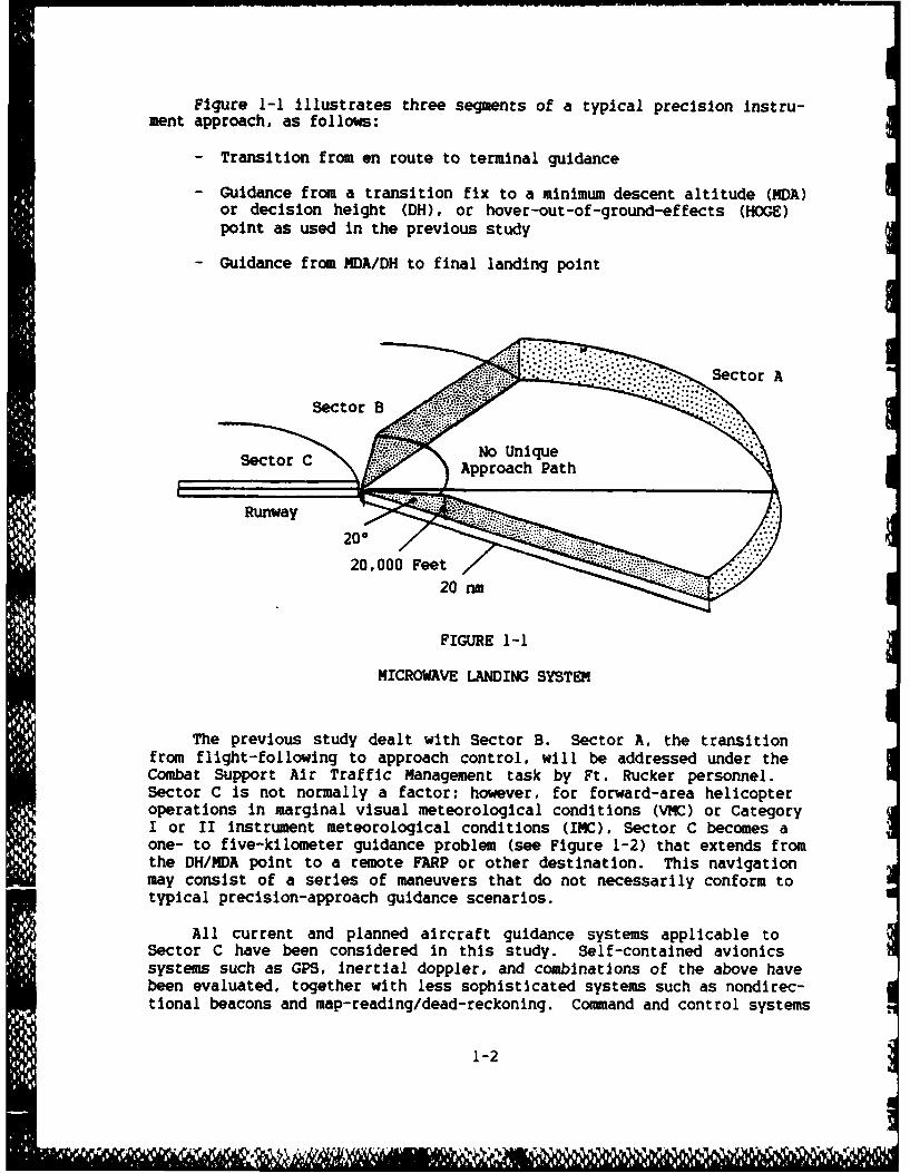
Figure 1-1 illustrates three segments of a typical precision instru-
ment approach, as follows:
- Transition from en route to terminal guidance
- Guidance from a transition fix to a minimum descent altitude (MDA)or decision height (DH), or hover-out-of-ground-effects (HOGE)point as used in the previous study
- Guidance from MDA/DH to final landing point
Sctor A
Secto B n
20,000 Feet20 nm
FIGURE 1-1
MICROWAVE LANDING SYSTEM
The previous study dealt with Sector B. Sector A. the transitionfrom flight-following to approach control, will be addressed under theCombat Support Air Traffic Management task by Ft. Rucker personnel.Sector C is not normally a factor; however, for forward-area helicopteroperations in marginal visual meteorological conditions (VMC) or CategoryI or II instrument meteorological conditions (IMC), Sector C becomes aone- to five-kilometer guidance problem (see Figure 1-2) that extends fromthe DH/MDA point to a remote FARP or other destination. This navigationmay consist of a series of maneuvers that do not necessarily conform totypical precision-approach guidance scenarios.
All current and planned aircraft guidance systems applicable toSector C have been considered in this study. Self-contained avionicssystems such as GPS, Inertial doppler. and combinations of the above havebeen evaluated, together with less sophisticated systems such as nondirec-tional beacons and map-reading/dead-reckoning. Command and control systems
1-2
Wol

FIGURE 1-2
DISPERSION OF AIRCRAFT
such as Position Location Reporting System (PLRS) or PLRS/Joint TacticalInformation Distributed Systems (JTIDS) Hybrid (PJH) were also consideredas potential terminal navigation aids.
The definition of ground guidance as used in the context of thisStLdy Is: A means to safely. efficiently, and rapidly aid in the movementof helicopters from their transition point of "landing" to a finaldestination.
1.3 METHODOLOGY
In conducting our evaluation, we addressed the following four tasksas defined in the contract Statement of Work:
- Review Army Requirements. Reviewed numerous documents andconducted extensive field interviews.
- Identify Alternative Systems. Reviewed specifications and helddiscussions with many Government and industrial laboratorypersonnel.
1-3
Q I( I IIJ 11 1ill Il l lli l ! l ll il , l ,Wr
- Evaluate Alternative Systems. Conducted aviator and engineerevaluations and merged the results.
- Identified and Documented Best Approach.
1.4 REPORT ORGANIZATION
Chapter Two provides an overview and determination of Army require-ments and possible alternative systems for helicopter ground guidance.Chapter Three addresses the evaluation, which includes a requirementssurvey by Army aviators, an alternative system survey by avionics engi-neers. a merging and evaluation of the two surveys, and a sensitivityanalysis. Chapter Four presents conclusions and recommendations.
Appendix A presents an overview of Army terrain flight levels andflight navigation procedures at very low altitudes. Appendix 8 describesthe evaluated alternative systems. Appendix C provides definitions of theground guidance general characteristics. Appendix D lists the militaryand civilian organizations visited and personnel interviewed.
1-4

5U
CHAPTER TWO
REQUIREMENT FOR GROUND GUIDANCE ANDALTERNATIVE SYSTEMS
U This chapter presents a discussion of the requirement for a groundguidance system, provides alternative systems to be evaluated against therequirement. and lists factors to be considered in the evaluation.
2.1 REQUIREMENT FOR GROUND GUIDANCE
Army tactical helicopters will be employed in the entire Corps/Division Tactical Area of Responsibility (TAOR). When Army helicoptersare deployed with maneuver brigades, there is an absolute requirement fortactical terrain flight, an extremely demanding task for the aircrew.On-board navigation equipment that will minimize the aircrew workload isrequired, since pilots must navigate in unfamiliar (often mountainous)terrain, around the clock, and in adverse weather conditions. Terrainflight is the employment of a helicopter in such a manner as to utilize
terrain, natural, and manmade objects to enhance survival by degrading theenemy's ability to optically and electronically detect, locate, and engagethe helicopter. Terrain flight involves the aircrew's constant awarenessof the position and location of enemy air defense systems in relation tothe planned flight route. Terrain flying includes three methods of flyingvery close to the earth's surface: low level, contour, and NOE flight(see Appendix A for further explanation of terrain flight).
Maintaining visual contact with the ground and using the topographicmap, together with the associated coordination required between the twohelicopter pilots are classic examples of elementary "pilotage," or a
Dbasic "ground guidance system." Numerous sensor systems exist by whichthe alrcrew can maneuver and navigate a helicopter at NOE altitudes.However, it is not currently possible or practical to install some of thelarge. heavy, and expensive systems in present or planned small tacticalhelicopters. The source of aircrew perceptual information (i.e., apilotage system) varies from the unaided eye for clear daylight conditionsto night vision goggles (NVGs) and forward-looking infrared (FLIR) systemsfor moon and starlight conditions to high-resolution radar imaging systemsfor an IMC environment.
2-1
Ue

With the exception of the new AH-64A Apache attack helicopter, theArmy aviator's primary method for ground guidance NOE navigation is ahand-held topographic map, NVGs if required, and a Doppler NavigationSystem (DNS), if installed. Both pilots wear NVGs when flying at night orwhen daylight visibility is severely reduced by adverse weather. Theaircraft's electronic heading reference indicator (compass) is used forazimuth information required while using the map. If available, theAN/ASN-128 or ANIASN-137 DNS provide present -position, ground speed, andsteering information and can be preset for the objective area position andvarious waypoints. The DNS is also completely self-contained, requiringno externally referenced navigation systems or navigation aids. Althoughthe DNS can be programmed for azimuth and distance information to waypointsthat assist the aircrew to track a minimum-risk route, it loses accuracyover distance flown. Present -posi tion updating is required to correctthis characteristic. Consequently, the aircrew will be using the DNS forback-up navigation when flying NOE. A hybrid navigation system will beused with the DNS in the near future for constant position updating.
Realistically stated, almost the entire Army helicopter aviatorcommunity is using a standard 1:50,000 topographic map for primary naviga-tion. This map is used to assemble and collate the myriad of Informationrequired to plot friendly and enemy force distribution, battle positions,aerial observation points, landing zones (LUs), primary and alternativeroutes of flight, FARPs, barrier features, location of wires and otherpassive hazards to flight, and friendly and enemy air defense systems.
The following section describes alternative current and futurenavigation and command and control systems that are planned for instal-lation in some present Army helicopters and the future single-piloted LHX.
2.2 ALTERNATIVE SYSTEMS
The alternative systems and a manual procedure that will assistaircrews with ground guidance evaluated in this report include existingand planned navigation and command and control systems. The alternativeswere limited to those which are capable of terrain flight navigation inthe immediate vicinity of a remote area landing zone that may include atactical precision approach system or for navigation to any location inthe Division/Corps TAOR. Table 2-1 lists the systems considered. The
.. ,~ following subsections provide descriptions to acquaint the reader with thesalient features of each. Appendix B presents detailed descriptions.
2.2.1 NATO Standardization Agreement (STANAG) 2351
The STANAG Is a manual procedure whereby individuals on the groundcan guide the helicopter pilots with hand and arm or light signals to amarshalling area. This procedure would assist the aircrew to air-taxifrom the LZ in adverse weather to an unfamiliar marshalling area a shortdistance from the LZ. This procedure is not a candidate for a groundguidance system; but these are the procedures that must be followed,especially In a NATO theater of operations. 'Pilotage" as used today and
2-2

TABLE 2-1
3 ALTERNATIVE GROUND GUIDANCE SYSTEMS
North Atlantic Treaty Organization (NATO) Standardized Agreement(STANAG) 2351, Procedures for Marshalling Helicopters in Multi-national Land Operations
Nondirectional Radio Beacon (NDB), AN/TRN-30(V)I(V)2
Lightweight Doppler Navigation System (LDNS), AN/ASN-128
Improved Lightweight Doppler Navigation System (ILDNS).AN/ASN- 13 7
Integrated Inertial Navigation System (IINS). AN/ASN-132
Position Location Reporting System (PLRS), AN/TSQ-129
PLRS/Joint Tactical Information Distribution System (JTIDS)5 Hybrid (PJH)
NAVSTAR Global Positioning System (GPS)
GPS/Doppler and GPS/Inertial Hybrid Systems
Night Navigation and Pilotage System (NNAPS)
Uwhich, in final form, uses these procedures is the manual procedure3evaluated.2.2.2 Nondirectional Beacon (NDB). AN/TRN-30 (VI)(V2)
This nondirectional, highly portable radio beacon can be employed ina tactical/semi-fixed or pathfinder configuration. It has a 46-kilometerrange with a 30-foot antenna. Although an NDB has no range informationcapability, it would assist the aircrew with terrain flight navigation byproviding a constant relative bearing to the beacon.
2.2.3 Lightweight Doppler Navigation System (LDNS), AN/ASN-128
The LDNS. in conjunction with the aircraft's heading and verticalreferences, provides accurate aircraft velocity, position, steering, anddistance-to-go information from NOE level to well above 10,000 feet. Itis a completely self-contained system. does not require any ground-basedaids, and only weighs 29.4 pounds. The system provides worldwide naviga-tion with position readouts available in both universal transverse mercator(UTM) and latitude/longitude displayed via a cockpit-mounted computerdisplay unit (CDU). Up to 10 destinations may be entered in either format.Present-position data entry format is also optional and independent ofdestination format. Waypoints selected from the topographic map to fly a
2-3
3

minimum-risk route to a destination can be preset, thereby easingconsiderably the pilot and copilot workload with NOE navigation. Changesin route or destination can be made during flight. During periods ofextremely reduced visibility the aircrew could use the system almostexclusively as a dead-reckoning navigator for short distances, if theflight began with a positive preset present position. Use of the topo-graphic map would not be eliminated but might be minimized.
2.2.4 Improved Lightweight Doppler Navigation System (ILDNS), AN/ASN-137
The AN/ASN-137 is a product improvement program (PIP) version of theAN/ASN-128. The AN/ASN-137 employs the MIL-STD-1553 data bus and elec-tronically centralizes the aircraft instrument headings on a single videoscreen with improved accuracy. Aircrew assistance with terrain flight isessentially the same for the AN/ASN-137 as for the AN/ASN-128.
2.2.5 Integrated Inertial Navigation System (IINS), AN/ASN-132
The IINS provides self-contained, passive navigation capability.Waypoints and destination features via a CDU are basically the same as forthe doppler systems. Currently, only special electronic mission aircraft(SEMA) applications have been identified for the IINS, which is currentlyPIP for the EH-60 Quick Fix, replacing the AN/ASN-86 INS. System accuracyis partially a function of the quality and frequency of present-positionupdates. These updates can be entered manually or automatically. if aTACAN station is available. Although most helicopter SEMA missions areflown in the division area at flight levels far exceeding terrain flightaltitudes, the AN/ASN-132 is an obvious excellent NOE navigator. Theaccuracy of the system is classified, but it is more accurate than adoppler navigator. The four major components (less the AN/ARN-l18 TACAN)weigh 144 pounds and require an initial alignment time of nine minutes.The ASN-132 provides the aircraft location with extremely high tolerances,exceeding the AN/ASN-128 or -137. In addition, it has no radar signature.
2.2.6 Position Location and Reporting System (PLRS), AN/TSO-129
PLRS is a ground commander's command and control UHF radio networkconsisting of up to 400 individual user units (UUs). The UUs are manpack-deployed or installed in vehicles or aircraft. Each UU automaticallytransmits a self-identifying signal burst on a precise time-orderedschedule, measures time of arrival of the other UU transmissions, andautomatically relays these measurements under a master station (MS)control. The MS does the position location and tracking as well asproviding report messages to the users and C3 function. The MS is alsoa fully automatic network manager. By substituting an airborne poweradapter for the manpack battery and a pilot control and display panel(PCDP), the basic UU adapts to the aircraft.
Terrain flight navigation will be greatly enhanced if a helicopter isPLRS-equipped. The PCDP, very similar to the inertial and doppler CDU,will display constantly the changing range and bearing to predesignatedlocations such as LZs or through minimum-risk waypoints. The aircrew can
2-4

interrogate and navigate to a UU at a fixed site or to a unit or vehicleon the move, including in-flight rendezvous with other PLRS-equippedhelicopters. When airborne, the command and control personnel. via theMS. can send zone proximity alerts or guidance away from or out of dangerareas. They could also cancel the original mission and forward allnavigation and ancillary information required to perform the new mission.The PLRS is not a primary aircraft navigation system, and it will noteliminate the pilot/copilot coordination required for ground guidanceusing the topographic map, but It will greatly decrease their navigationworkload. The PLRS will supplement and back up the aircraft primaryself-contained navigation system.
2.2.7 PLRS/JTIDS Hybrid (PJH)
Building on the developments and investments already made in PLRS andJTIDS, the new PJH is a hybrid of both. The Army has decided on theacquisition of PJH instead of PLRS. PJH forms an enhanced, highly jam-resistant command and control system, encompassing both air and groundforces. All PLRS capabilities are retained but when compared with PLRS,PJH will significantly increase the quantity of data that can be trans-mitted between battlefield components. It will also permit enhancedinterface with USAF and other service JTIDS-equipped aircraft supportingArmy ground units and will establish direct user-to-user communicationslinks. PJH employs the enhanced PLRS user unit (EPUU) for manpack,vehicular, and aJrcraft installations. The net control stations (NCSs),located at the division and brigade rear areas, are the upgraded PLRSmaster stations.
Both PJH and PLRS will assist helicopter aircrews with terrain flightnavigation, as described in Subsection 2.2.6. PJH's increased communica-tions capability and the capability for direct aircraft EPUU to otherEPUUs without going through the NCS should also assist the aircrew withmore effective and timely use of the system for terrain flight navigation.
2.2.8 NAVSTAR Global Positioning System (GPS)
GPS is a multiservice space navigation system with the capacity toprovide highly accurate, three-dimensional position, velocity, and time toan infinite number of users anywhere on or near the earth. GPS consistsof three segments -- space, control, and user. The space segment willconsist of 18 satellites plus three active spares. The constellation isdesigned so that a minimum of four satellites are always in view, which isthe number required for an accurate fix. The DoD-specified accuracy willbe within 15 meters. The Army plans to install user equipment in manpack,vehicles, and aircraft. Army Aviation will be a major user, and presentplans are to install GPS in aircraft equipped with a doppler or inertialnavigation system.
GPS is passive and will provide the aircrew with present position orrange and bearing to waypoints, allowing navigation between any two pointsthe aircrew selects. With its three-dimensional capability. GPS canprovide course and vertical guidance information for nonprecision
2-5
%W-

approaches into tactical LZs. When available, GPS can provide redundancywith doppler or inertial navigation systems, thus increasing the probabil-ity of mission success.
The primary advantage of GPS versus other systems is its remarkableconstant accuracy that greatly assists an aircrew in navigation in terrainflight. Since GPS is passive, this will allow NOE flight in closerproximity to high-threat air defense systems. There is no requirement formanual updating regardless of time flown or distance traveled. Thisfurther decreases the aircrew workload. However, GPS will not completelyeliminate the requirement for topographic maps.
2.2.9 GPS/Doppler and GPS/Inertial Hybrid Systems
The AN/ASN-128. AN/ASN-137 doppler, and AN/ASN-132 inertial self-contained navigation systems (SCNSs) and NAVSTAR GPS have been describedin previous paragraphs and in Appendix B. The aircrew must manuallyupdate both doppler and inertial navigators with present-position data tomaximize system accuracy. Army aircraft equipped with a SCNS will haveGPS user equipment (UE) sets installed, and GPS will continuously updatethe SCNSs' present position. An integrated GPS/SCNS console-mountedcontrol indicator unit (CIU) will be installed.
Using the AN/ASN-128/GPS hybridization as an example, the CIU willprovide for control of the AN/ASN-128 and readout of navigation quantitieson the basis of the doppler velocity measurement. The CIU will supportseveral navigation modes: AN/ASN-128-aided GPS navigation, unaided GPSnavigation, AN/ASN-128 dead-reckoning without GPS satellite measurement,and memory (position based on last known velocity vector after loss of allGPS and AN/ASN-128 data).
The aircrew assistance with terrain flight listed previously is alsoapplicable to a GPS/SCNS system. Further, the GPS/SCNS hybridization andits inherent significant increase in navigation accuracy should permit theaircrew to use the system for dead-reckoning with almost complete confi-dence. It would not be inconceivable for the pilot/copilot "pilotage"workload to be considerably reduced, although not completely eliminated.Aircrew workload would also be decreased by eliminating the requirementfor SCNS manual position updating.
2.2.10 Night Navigation and Pilotage System (NNAPS)
The NNAPS is a special-purpose, very high-speed digital processingsystem that uses digitized topographic data stored in an airborne storagedevice to improve current operational capabilities in autonomous naviga-tion, topographic map generation, and flight and tactical symbologygeneration. It is currently in the exploratory development phase: and aprototype system is installed at the Avionics Research and DevelopmentActivity (AVRADA), which is integrated with the Advanced HelicopterImprovement Program (AHIP).
2-6

The NNAPS consists of two major subsvytems, a digital map generator(DW.) and an integrated mission planning O.Lation (IMPS). The DMG isinstalled in the aircraft and includes the topographic map display, whichcan be scaled down in four increments -- from 24x24 -km to 3x3 km. The3 IMPS (which has its own DMG) is required to generate the mission tapes forthe airborne DMG. The IMPS will permit aviators and/or operations/intelligence personnel to plan a mission, enter the information into astorage device such as a cassette, and then transfer that data to theaircraft.
By comparing terrain below the aircraft with stored terrain data, theNNAPS has the potential for extremely high accuracies in position informa-tion and does so as an autonomous system. The digital terrain elevationdata base is used to automatically. update the doppler navigation system.giving it a potential accuracy of 50 meters or less. These same data alsoform the foundation of the digitally generated moving-map display. Thistopographic map display (in the aircraft and IMPS) can be used forpreflight planning or in-flight evaluation. The topographic map displaypresentation on a cathode ray tube (CRT) appears as a contour-line mapwith color-coded terrain elevations. The DMG also provides perfectregistration and overlay of flight symbology. The system will feature aunique control display unit that will provide a high degree of flexibilityin generating displays for NOE operations.
The Aviation Branch has not identified any definite aircraft applica-tions to date; but possible applications are in the OH-58D and AH-64aircraft.
The NNAPS will improve aircrew performance in NOE and low-visibilityenvironments and reduce aircrew workload through the elimination of hand-held maps. Navigation workload and head-down time in the cockpit will beminimized. In addition, aviators require many different types of informa-tion on a single map, yet map clutter must be avoided to the greatestextent possible. With the DMG the aircrew can select the informationneeded to provide a map optional for the momentary situation, therebycontrolling the classes of information that are required to be displayed(e.g., vegetation. highways, hydrography). Since the present position ofthe aircraft is always displayed, versus the expected position on theprogrammed course, theoretically the aircrew is never "lost." Anotheraircrew aid to navigation via the DMG is the impressive feature of anyinformation to be upgraded through data links from the ground or otheraircraft. An entire route of flight or a new destination can be passed.and since present aircraft position Is displayed. NOE flight to the changedroute should be routine.
2-7
2.2.11 Other Systems Considered But Not Evaluated
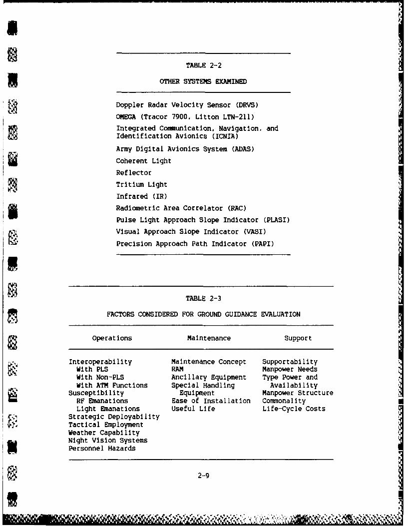
Table 2-2 lists the systems considered for ground guidance navigationbut not evaluated. The reasons for elimination from further considerationare as follows:
- The Doppler Radar Velocity Sensor (DRVS) was being developed as apossible doppler navigation system replacement but has beeneliminated from further consideration according to personnel atAVRADA.
- OMEGA systems with growth potential for GPS updates were originallyincluded. These systems were eliminated because of the severeinaccuracy of OMEGA, and the programmed GPS will be more accurateindividually than in combination with OMEGA.
- Integrated Communication, Navigation, and Identification Avionics(ICNIA) is without a stated navigation system and therefore cannotbe considered a candidate by itself.
- The Army Digital Avionics System (ADAS) is strictly a test bed;thus it is excluded since there are no plans for deployment. Itwill be used only for test, evaluation, and demonstration.
- The various lighting systems (e.g., coherent light, reflectors,tritium light, infrared, pulse light approach slope indicator[PLASI], visual approach slope indicator [VASI], and precisionapproach path Indicator [PAPI]) were eliminated as a result of theexploitability, numbers required, and the manpower required toreorient every four to six hours in the forward area or cross-front line of troops (FLOT).
- Radiometric area correlator (RAC) technology definitely offerspromise if the cost can be kept low; however, there is no concertedeffort at present to develop this as a navigation system, althoughthe system in the AH-64 is similar. The development of a RAC-typesystem was recommended in the previous report.
2.3 FACTORS CONSIDERED
The U.S. Army Air Traffic Control Activity (USAATCA) originallyprovided 23 factors to be considered in evaluating alternative groundguidance systems. After reviewing these factors, we prepared a discussionpaper that was used to gain USAATCA's concurrence on a general definitionand regrouping of the factors. A copy of this discussion paper is provided -in Appendix C. The factors, which were grouped into categories of opera-tions, maintenance, and support, are presented in Table 2-3.
2-8
N. 74"
I
TABLE 2-2
3OTHER SYSTEMS EXAMINED
Doppler Radar Velocity Sensor (DRVS)
OMEGA (Tracor 7900, Litton LTN-211)
Integrated Communication, Navigation, andIdentification Avionics (ICNIA)
Army Digital Avionics System (ADAS)
Coherent Light
Reflector
Tritium Light
Infrared (IR)
5Radiometric Area Correlator (RAC)Pulse Light Approach Slope Indicator (PLASI)
Visual Approach Slope Indicator (VASI)
Precision Approach Path Indicator (PAPI)
TABLE 2-3
FACTORS CONSIDERED FOR GROUND GUIDANCE EVALUATION
Operations Maintenance Support
Interoperability Maintenance Concept SupportabilityWith PLS RAM Manpower NeedsWith Non-PLS Ancillary Equipment Type Power andWith ATM Functions Special Handling Availability
Susceptibility Equipment Manpower StructureRF Emanations Ease of Installation CommonalityLight Emanations Useful Life Life-Cycle Costs
Strategic DeployabilityTactical EmploymentWeather CapabilityNight Vision SystemsPersonnel Hazards
2-9
e

2. 4 SUMMAY
This chapter presented the requirement for a ground guidance system,alternative candidate systems, and factors to be considered in evaluatingthese systems. Chapter Three describes our methodology and evaluation ofthe systems.
2-10
% %.
CHAPTER THREE
FACTOR AND SYSTEM EVALUATIONS
This chapter presents a discussion of the aviator factors survey,Including problems at NOE levels, the evaluation methodology, the engineeralternatives survey, the results of our evaluation, and a sensitivityanalysis. Appendix D is a listing of all personnel interviewed andlocations visited during our evaluation.
3.1 FACTORS SURVEY
After developing the set of factors in conjunction with USAATCA,ARINC Research contacted the U.S. Army Development and Employment Agency(ADEA) at Ft. Lewis, Washington; the XVIIIth Airborne Corps at Ft. Bragg,North Carolina; and the 101st Airborne (Air Assault) Division at Ft.Campbell, Kentucky. Tables 3-1, 3-2. and 3-3 provide a cross-sectiondescription of surveyed personnel and their experience in NOE hours andaircraft flown. These aviators were asked to describe problems with andrequirements for guidance at very low altitudes in preparation for aneventual evaluation of ground guidance requirements.
one thread that weaved consistently throughout the surveys is thatflight minimums In peacetime are generally 300 feet vertical and 1/2 milehorizontal visibility (see Table 3-4). These minimums produce a phenomenanot noticeable for pilots who may only practice navigation at NOE altitudesin relatively clear (VMC) conditions; that is, terrain features, bothnatural and manmade, may not be as readily available to orient with, andfrom, when adverse weather covers the tops of, or obscures, prominentfeatures. This prompted the question of what is adverse weather? Alloperational and organizational (0&0) plans for U.S. Army helicopters inthe immediate future require the aircraft to operate either in all weather(most severe case) or adverse weather. There is no approved definitionfor "adverse weather" in the U.S. Army lexicon. ARINC Research heldexhaustive discussions at the three previously mentioned locations plusDCS for Combat Development. Ft. Rucker, and USAATCA, Ft. Huachuca. The
3-1

£
TABLE 3-1
EXPERIENCE PROFILE OF PERSONNEL SURVEYED (FT. LEWIS)
Number of Aircraft Flying
HoursRank NOE* Now Former Training Location
0-4 200 UH-lH, OH-58 U-8, T42, Unit
T41. 0-1
200 OH-58A/C UH-1H Unit
CW4 1500 UH-60 OH-58, UH-l NOE School, Yakima, WAWest Germany
750 OH-58 AH-IG Unit
2000 CH-47B UH-IA/B/D/H, UnitOH-6A/B/C,OH-58C, CH-47C
1000 JOH-58C CH-47, UH-I Unit V
*Range f 200 to 2,000 hours NOE. Average = 940 hours.
consensus definition resulting from these discussions is a function of theaircraft and its mission requirement. For example:
- Attack aircraft: Adverse weather is a function of visibility andthe minimum/maximum range of its weapons system -- perhaps 50 feetvertical and 500 feet horizontal.
- Cargo aircraft: Adverse weather is a function of the type andlocation (external/internal) of the load -- perhaps 50 feetvertical and 100 feet horizontal.
Another major concern for all the pilots was the reliability andmaintainability of any ground guidance system finally accepted. Manyquestioned the ability of today's Army to maintain more sophisticatedequipment and stated that there were insufficient maintenance techniciansto maintain even today's VHF omnirange receivers (VORs) and automatic
3-2 4
~An

TABLE 3-2
EXPERIENCE PROFILE OF PERSONNEL SURVEYED (FT. BRAGG)
Aircraft Flying
Number of ______________
HoursRank NOE* Now Former Training Location
0-3 300 OH-58A/C UH-IH Unit
0-2 50 UH-lH Unit
175 OH-58C Unit, Ft. Irwin(National TrainingCenter), JAAT
S CW3 250* CH-47B/C/D UH-ID, H UnitsHughes 500C/D
CW2 100 U1. -IH Unit. El Salvador,Egypt
100 UH-60 Unit
700 UH-60 UH-lH CONUS Units andN Overseas
*Range = 50 to 700 hours NOE. Average = 240 hours.
direction finders (ADFs). In addition, the supply problems are difficulteven now for today's aircraft and air traffic control (ATC) systems.
After gathering the comments from several U.S. Army tactical aircraftunit locations and the Ist Marine Aircraft Weapons Training Squadron atthe Marine Corps Air Station, Yuma, Arizona, an independent list ofaviator-desired requirements was priority ranked at the last locationvisited, Ft. Campbell, Kentucky (see Table 3-5). The factors selected bythe aviators did not have a direct correlation with the factors agreedupon originally (Section 2.3 and Appendix C). These new factors wereranked from 1 to 23 (1 = good, 23 = low). The average score for each wasthen computed. For example, accuracy was rated first (1) by three aviators(I x 3 = 3) and second (2) by five aviators (2 x 5 = 10); therefore, thetotal rating points were 13 and total raters (8 raters or aviators) provide
3I

TABLE 3-3
E?XPERIENCE PROFILE OF PERSONNEL SURVEYED (FT. CAMPBELL)
Aircraft FlyingNumber of
HoursRank NOE* Now Former Training Location
0-4 200 UH-60 OH-58, UH-1 Unit
CW-4 500 CH-47D OH-6A/C Unit
1000 UH-60 UH-l Unit
CW3 1000 UH-60 UH-1, AH-l,OH-58
1000 UH-60 UH-1, AH-l Unit
CW2 20 UH-60 UH-1 Unit
40 UH-60 OH-58 Unit
500 UH-60 UH-lH Unit
500 OH-58A/C Lq-IH Unit
*Range = 20 to 1,000 hours NOE. Average = 530 hours.
an average of 13/8 or 1.63. The factors were then listed by descendingaverage and assigned an ordinal rank. The factor "accuracy" rated one(1). Note that three of the aviator factors had identical averages:therefore, a suffix was added to differentiate, i.e., 13A. 13B, and 13C.
3.2 EVALUATION METHODOLOGY
The original methodology discussed with USAATCA in October 1985 wasto have both the factors and the alternative systems rated by U.S. Armyaviators. However, because of the Army aviators being unfamiliar withseveral of the systems, this approach was modified. The aviators selectedand ranked the factors presented in Chapter Two, Section 2. Then, civilianengineers, who were also pilots, performed the comparative ratings of
3-4

TABLE 3-4
3 ARMY VFR WEATHER MINIMUMS(UNCONTROLLED AIRSPACE)
Visibility*Ceiling ______
Operation (Feet) Rtr ieWing Wing
la t Terrain 300 1/2 1
Mountainous Terrain 500 1/2 1
Night
Flat Terrain 500 1 2Mountainous Terrain 1000 1 3
3*Conditions as reported or forecast in statuteor nautical miles.
Notes:
1. When weather conditions are less than thoseabove, tactical helicopter training may beconducted in approved tactical maneuver/training areas with the following
restrictions:
- W hen clear of clouds- At an airspeed allowing visual contact
with other aircraft for avoidance purposes- With 1/2-mile visibility- With ATC clearance when operating in a
control zone- With approved vertical helicopter IFR
recovery procedures- With aircraft equipped for IMC flight and
with appropriate avionics
2. Information extracted from Table 4-1, Change3. AR 95-1, 5 August 1984.
3-5
Le

TABLE 3-5
REQUIREMENTS RATINGS
Average OrdinalFactor Rating Ranking*
Accuracy 1.63 1Reliability 1.75 2Confidence 3.00 3Maintainability 4.25 4Low Workload, In-Flight 4.75 5Low Workload, Pre-Flight 5.29 6Terrain Information 5.67 7Night-Vision-Capable 6.00 8No Ground Site Dependency 6.17 9Passive Aircraft 6.29 10Distance Display 6.40 11Bearing Display 6.50 12Human Factors 7.00 13AIntegrated with other Displays and Avionics 7.00 13BNot Platform-Unique 7.00 13CVariable Scale 7.33 14Weather 7.50 15BITE 8.00 16Passive Ground 8.50 17Commnon Feel 10.00 18Low Cost 11.50 19Ground Deploy < 30 Minutes 15.00 20Easy Training 16.00 21
*Used as a contributing factor number; see Table 3-6.
alternative systems versus the factors. The methodology Is illustrated inFigure 3-1. Table 3-5 was the initiation point. There was not a directcorrelation of the aviator factors and the original factors.
In some cases the relationship was obvious; in other cases the 10 to12 hours of dialogue on cassette recordings was used to determine theessential nuance intended by the aviators. on the basis of this exhaustiveexamination, the aviator factors were merged into the original factors(see Table 3-6). In Table 3-6 the second column has the ordinal rankingas used in Table 3-5. Since not all aviators chose to rank all theirfactors, the sum of rating points and the number of total raters
3-6

Merge ofAviators AviatorRate Their FactorsFactors With Original
(Table 3-5) Factors(Table 3-6)
EngineersReutRate Systems Merge and *Rne atrVs. Original Evaluate (TRake Factor
Factors (Table 3-8)(Tbe-6(Table%3-7) 9 Ranked Systems
(Table 3-8)
FIGURE 3-1
SURVEY METHODOLOGY
(aviators) were listed. A global average was created for each of themajor factors (subeleinents of interoperability and susceptibility weresunned) by dividing rating points by total raters. An example of thismerging is "RF (Emanations)" under "Susceptibility." This factor wascomposed of numbers 10 and 17. which were "passive aircraft" and "passiveground" in Table 3-5. Seven aviators rated passive aircraft with anaverage score of 6.29; therefore, its score is 44 rating points (7 x6.29). Likewise, six aviators rated passive ground with an average of8.50; therefore, its score is 51 rating points. The sum of these is 95,as shown in Table 3-6. The total number of raters Is 13. Susceptibilityglobal average was then calculated by adding rating points for both "RF"and "Light" (95 + 101), equaling 196, and dividing by total raters (13 and14), giving a global average of 7.26. This "global average' became theaviator weighting factor used in Section 3.4.
3.3 ALTERNATIVES SURVEY
Engineers with helicopter experience rated each of the systems versusthe original factors (see Table 3-7) on the basis of an analysis of avail-able systems and discussions with avionics engineers. One category thathas not been mentioned directly, but was prominent in the engineerdiscussions and will be used as a discriminator, is 'duality of purpose":that is, systems that are programmed for another purpose, but that willfulfill the second or parallel mission of ground guidance, will bearheavily in the selection of the best approach.
3-7
*N V''
",

coV I w I -W I- -i IC 0-I -
al' f- 0 in 6-4O Ln -4 %00M nc
0 f i %C I n r-c cc i * % CDI C I at~ M w MLnO
(n %0 r- 00 --Ct
-~~~~~. 17 J~ O--I
Ch in. :0 *. -M.- - -
I1~61 0. &J1.0
C-4 M0 0.- 41
6.6. 6 -
'.D 0. 40
o~I In 0 .Q~t-4 cr W La' 1 .~~~~~~~L -4 )- - - U 0 91~ I ' .
-~~~ 41.C ' U)~ - 1 U0 . d
0 6. -iC4 C4 U W.' 00 N~-. a0 0 . 01C .9~- In 00.- -i .4 -1 U 6 '. -u 'nO -u~ 0. . 4h 4~' 6. C CC 'U - 1Ch'U U.' >.'-
6.~~~~~~~L -4.6.~C. ~'o - h 0 U 0
'U0~~ -0. M- C.'~ ~AU 4w 0
ol c ,u 000
3-8 -aA .06

U
TABLE 3-7
3ALTERNATIVES SURVEYAverage Rating by System
Factor GPSInte-
Pi lotage NDB DNS INS PLRS PJH GPS NINAPS grated
Interoperability NA I NA NA 4 3 2 NA 2Susceptibility NA 7.5 6.5 1 2 2 4 6 4Strategic Deployability 1 2 1 1 7.5 7.5 1 5.5 1Tactical Employment 1 7 1 1 6 6 1 5 1Weather Capability 8.5 7 4.5 4 4.5 4 5 1 2Night Vision System Use 8.5 1.5 1.5 1.5 1.5 1.5 1.5 4.5 1Personnel Hazards 1 4.5 3.5 1 1 1 1 1 6Maintenance Concept*RAN**Ancillary Equipment NA 4.5 1.5 1 7 7.5 3.5 6 4Special Handling EquipmenttEase of InstallationttUseful Life NA 4 2.5 2.5 4.5 6 1 7.5 1Supportability 1 1.5 2 6 7 8 2 9 2
Manpower Needs 1 9 1 1 6.5 6.5 1 7.5 1Type Power and Availability NA 1 3 3.5 5.5 4 1 6 NAModular Structure#
Commonality 1 4.5 6.5 7 3 3 1 4 8.5Life-Cycle Costs 1 2 4 5.5 5.5 7 2.5 9 6.5
Total Score 24 5" 38.5 36 65.5 67 27.5 72 40
Scored Areas 9 14 13 13 14 14 14 13 13
Average 2.7 4.1 3.0 2.8 4.7 4.8 2.0 5 5 3.1
Ranking 2 6 4 3 7 8 1 9 5
-Not defined for all systems. but engineers believed this would be set to the Army's advantage
and could see no rating inequality.**RAM data are highly controversial, are frequently not releasable, and/or are classified. Insome cases, data provided were significantly different. in other cases data were from speci-fications only. Appendix C provides a table of values for number of maintenance levels. MTBF.MTTR, and estimated number of avionics boxes. Without reliable data. the category was notgraded: however, a sensitivity analysis was conducted. allowing all except "pilotage" to berated I to 8. These results are also provided in Appendix C and show relatively little rankingchange.
tSpecial handling equipment was included in ancillary equipment rating.ttEase of installation was considered part of RAN: therefore. it was not rated.#Modular structure was considered part of original design and not relevant to rating: there-fore. the engineers declined to rank.
3-9
A.?
L e k9 u VIy I zig I?. \ ~',

3.4 FINAL SURVEY MERGE AND EVALUATION
A compiled matrix (Table 3-8) was required that would provide anumerical value by merging the engineers' survey (Table 3-7) and theaviators' ratings (Table 3-6). For example. Table 3-8 has a value of 4.7for NDB interoperability, derived as follows: from Table 3-6, interopera-bility rated 4.69. In Table 3-7, the engineers rated NDB interoperabilityas 1.0. The value in Table 3-8 was developed by multiplying 4.69 (inter-operability rating) by 1 (NDB interoperability rating) = 4.69. The 4.69was rounded to the tenths column (4.7). The column scores were thensummed (Total Score). The applicable global averages were summed only forthe rated factors (Scored Areas). The average was determined by dividingthe Total Score by Scored Areas; i.e., Pilotage: 132.5 divided by 57.21 =
2.3.The merge of these two ratings (Table 3-8) is significant in that
neither rating group knew the other's results: yet, when the relativerankings of systems are examined (Table 3-7 and 3-8), the ranking remainsthe same.
3.5 SENSITIVITY ANALYSIS
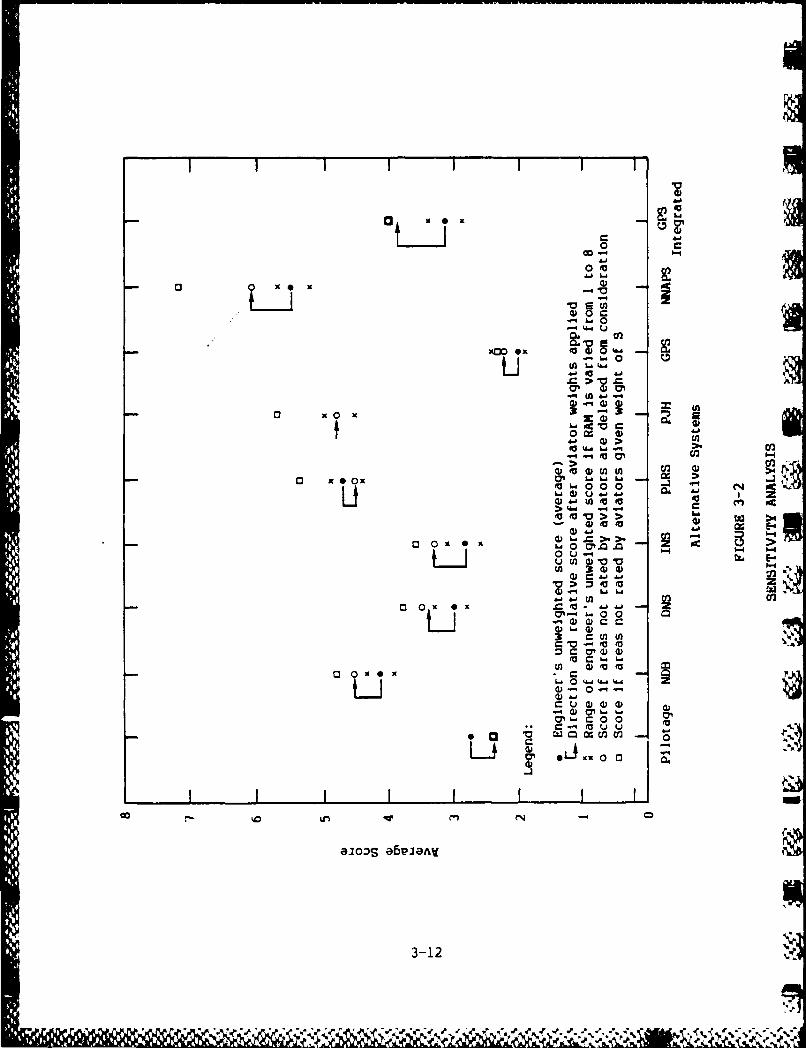
As noted in Table 3-7. the RAM versus alternative systems evaluationreceived no ratings because of the lack of or inconsistency of data.However, since reliability and maintainability ranked so high among theaviators, RAM was artificially varied from values of 1 to 8 on the engi-neers survey, as shown in Figure 3-2. The high and low of this variationare delineated by an X. There is an overlap in average scores of DNS,INS, and GPS integrated. In addition, and to be expected, there is anoverlap of PLRS and PJH average scores. The areas not rated by the avia-tors were also examined, first by deletion, then with a weight of five.There is no significant change.
One item of numerical significance not previously mentioned is thesubstantial difference between the present B-kit unit cost of INS(approximately $240,000) versus DNS (approximately $30,000 for ASN-128).This will be a discriminator when choosing a system, since the U.S. Armyis currently purchasing significant quantities of DNS and very few of theINS. At the estimated costs provided, there would be almost a $1 billiondifferential in outfitting the U.S. Army aviation fleet.
3.6 SUMMARY
GPS by itself ranks first; however, the GPS capability will not berealized until the 1990s. leaving the system of choice as 'pilotage" andthe maps. However, the next systems of choice (in order) are INS, DNS,and GPS hybrid. DNS is a more desirable choice, since the sheer cost ofoutfitting the Army aviation fleet with INS is overwhelming and asignificant number of helicopters currently have a DNS. Other systemssuch as PLRS and PJH do not rate well, simply because they have not been
3-10
4 % .o .... ' -".' " , ''. 5 " %%""5".5 5 %' "5" " '% '. -" "-. '. ".' ..

aa%o -%o.0%
qo ~ ~ ~ ~ G c-q~ O q ~ ~
00'n %0 %0 tt% 4O ft
0% 0 %04 - tn CN - 00- - rC4 N
qo 'n=&~ - ~ a 0o Go k n c
,a Ln N- w. -r- tn 0% v% 00 C; NN C-:- 00" GoN
00 =
'a Ca ucc.
c c~) NO LC% C n0. -- q =~% 2 !C: 9 %'-!0 L
w ; (- tn 101 N0 0 M 0 M 0 N M M~-j
cN
C"-
-'crr- 0% NC'O % ' %n No
N V)100
en zz- --- V-cVI V r%
0.>
0..
7. 0
4.'0, j0 >0 (-'a . >.0. "m vo - PC,60-i 4
b...OU 0 '-~ 7.Z-I; 0504j. i... Ma u o 0 Li 'a
UW CO 'aO-r
6. 4) j3-11
(Duf "- 4, (D ~
OL0J 0
0 0)
O
-~L0
41 ~ ~ 6 0.id
03 x 0 2
41' > U3
-4 'a tr-4
x x 0~ ox 6666E L0 0 - - (
Lt u 0 4.6 .j 4.4
> 4. ..00 >41z
0 U-L-i~~4i v 1" C.E
-A X 0) 0
0 0 x~ 0 U2 = a 1 .
0P- 0 0
.0~ ~ V O )fC ~ -
'0 0-*. D 4&4 L6.4
a-12C U 4) ) do d
) 0 6 . O

thought of as navigation systems. NNAPS has too little present exposureto rate higher; however, a system such as this must be utilized to fulfillfuture one-pilot helicopters.
3
U
U
~3-13

aw
CHAPTER FOUR
CONCLUSIONS AND RECOMMENDATIONS
4.1 CONCLUSIONS
On the basis of the evaluation conducted, ARINC Research presents thefollowing conclusions:
- Systems with a dual capability, Including the capacity to provideground guidance at NOE altitudes in IMC conditions, are preferableinstead of a single-purpose system developed strictly for theground guidance mission.
- The near-term system of choice is the DNS, the AN/ASN-128, or the-137. We have concluded that the DNS is preferable to theAN/ASN-132 INS, because of the relatively high cost of the -132.Similarly. we have concluded that the DNS is preferable to theGPS. because of the great uncertainty in the fielding date ofGPS. However, without the ability "to see" in Category III IMCconditions, the inaccuracy of the DNS system, and the possibleexploitation of the doppler signal, the pilotage system will stillbe primary and the aircrew must remain in eye contact with terrainfeatures.
- The mid-term choice is DNS with GPS integrated. The pilotagesystem will remain primary.
- The far-term choice is the same as the mid-term, but a NNAPS-typesystem must be provided if there will be single-pilot aircraft,e.g., LHX.
- Currently. there is limited adverse weather NOE capability intoday's aircraft, although new night vision and IR systems offeradditional capability. No present helicopters can fly IMC at NOEaltitudes.
- PJH, although a command and control system, will prove useful butonly as a back-up navigation system.
4-1

Inertial navigation systems (INS), although much more accurate andless susceptible than DNS, are far too expensive (approximately$240,000 for INS versus $30,000 for DNS per B-kit) for the severalthousand non-SEMA aircraft.
4.2 RECOMMENDATIONS
On the basis of the results of our evaluation, the following actionsare recommended:
- The pilotage system should be retained, and pilots should betrained continuously in the two-man system of flying NOE, usingthe topographic map. Doppler navigation should be used to assist.
- Procedures must be developed and practiced on how to quickly andefficiently transition from the Army Precision Landing System(APLS) sequence to ground guidance, especially for conditions lessthan VMC.
- The following are the ground guidance systems of choice:
-- Near term: Continue to provide DNS (AN/ASN-128/137) foraircraft required to operate at NOE altitudes, especially inthe forward area and cross-FLOT.
-- Mid-term: GPS should be provided and should be fully inte-grated with DNS.
Far term: Same as mid-term plus a NNAPS-type system that,coupled with a heads-up display, is mandatory in envisionedsingle-pilot aircraft when operating in NOE. Far-term solu-
tions must be carefully monitored to preclude excessive work-loads or possible loss of pilot skills in basic navigationwith map and compass.
4-2
I *~ V

APPENDIX A
AIRLAND BATTLE AND TERRAIN FLIGHT
This appendix presents an overview of the AirLand Battle and adiscussion of terrain flight, together with a description of some of theterrain flight problems at NOE levels.
1. ARMY DOCTRINE
AirLand Battle doctrine requires employment of tactical helicoptersas an integral part of the combined arms team, who must perform a varietyof tasks. Army aviators must be trained to enhance the ground commander'scapabilities in one or more of the five functions of land combat: fire-power, intelligence and electronic warfare (IEW). maneuver control, airdefense, and combat service support. These functions of Army aviationrequire an impressive array of diverse missions, and the missions requireddepend on the aviation unit type, the combat arm served, the tacticalsituation, and the type helicopter.
2. ARMY TERRAIN FLIGHT LEVELS
Terrain flight consists of three levels of flight with varying degreesof difficulty:
- Low-level flight is flight conducted at a selected altitude,approximately 100 feet above ground level (AGL) to avoid detectionand observation. Low-level flight is normally conducted on apreselected straight line and is flown at a constant airspeed andindicated altitude.
- Contour flight is flown at approximately 50 feet AGLI conformingwith the contours of the earth's surface. Contour flight takesadvantage of available natural or other concealment and is charac-terized by varying airspeed and altitude as vegetation andobstacles permit.
- NOE flight is flown as close to the earth's surface as vegetationand obstacles permit while generally following the contours of theearth's surface. It is characterized by the varying of airspeed
A-I

and altitude as influenced by the terrain, weather. ambient light,and the enemy situation. A longitudinal axis is selected pointingtoward an objective; but when flying toward the objective, theaircrew uses a weaving and devious route oriented along the axisto take advantage of the cover and concealment afforded by terrain,vegetation, and manmade features. Airspeed may be as slow as zero(hovering), and altitude is usually below prevailing vegetationlevels.
3. TERRAIN FLIGHT PROBLEMS A
As a result of the projected air defense weapons threat, Army aviationis committed to NOE flight (including cross-FLOT operations); however, itgreatly increases the likelihood of geographic disorientation resultingUfrom the aircrew's limited view of checkpoint features useful innavigation.
A helicopter aircrew that has made an instrument approach to a remotelanding zone may break out under the ceiling In weather that precludesimmediate terrain flight to an objective area. They could then air-taxito a concealed area guided by a marshaller using hand and arm or lightsignals. If the ceiling and visibility permit terrain flight, the aircrewcould continue to the objective area that could be a tactical objective,FARP. a medical evacuation (MEDEVAC) point, or resupply location. Thedistance from the point where the instrument approach terminates to thetactical objective may vary from a few hundred meters to more than 10kilometers. If the objective area is In the vicinity of the maneuverIbrigades, an NOE path that will avoid known or suspected enemy air defensesystems must have been preplanned or must be transmitted to the aircrewvia a command and control system.
Unlike low-level or contour flight in which an aircrew can follow aroute by identifying a series of preselected checkpoints, NOE flightrequires continuous orientation by Identifying all terrain features byreference to a topographic map, normally 1:50,000 scale. This is anextremely demanding and dangerous activity for the aircrew. requiringprecise teamwork and coordination. It is essential that the pilot at theflight controls concentrate exclusively on controlling the aircraft andclearing obstacles. He must be free at all times to keep his visiondirected outside the cockpit, avoiding distractions, particularly cockpit-related ones, which would hinder his external scanning pattern. The pilotannounces his visual terrain and landmark information to the copilot toassist in navigation. The copilot must remain oriented at all times usingthe map, and also using whatever navigation systems or instruments areaboard that particular helicopter. He informs the pilot of the directionand altitude to be flown and appropriate airspeed adjustments for timingpurposes. He also assists the pilot by monitoring cockpit instruments andthe mechanical functioning of the aircraft. The lower airspeeds of NOEflight allow the pilot the opportunity to see obstacles and hazards and toreact by maneuvering to avoid them. Adverse weather, especially reduced*
A-2
...... ......

visibility, requires further airspeed reduction and speeds may range fromhover to fast air-taxi.
Adverse weather is the most serious hazard to NOE flight, especiallyin mountainous terrain. When the aircrew's visibility Is reduced byflying into the sun or by haze, drizzle, rain, fog or snow, altitude mustbe increased and/or airspeed reduced to gain additional time to react toavoid obstacles. Obviously, altitude cannot be increased if this changewill place the aircraft in an enemy air defense system envelope.
A
~A-3
aU
APPENDIX B
3 ALTERNATIVE SYSTEM DESCRIPTIONS
IThis appendix provides details of the evaluated alternative systems.
B-1 .
P U

NATO STANAG 2351
The objective of this agreement is to standardize procedures for theUnited States and the other NATO countries to be used by marshallers/guides directing ground measurements of helicopters in multinational landoperations. Marshallers are trained to use hand and arm or lightsignals. It is a common procedure for contact between marshallers/guidesand helicopter aircrews approaching a landing site to load or unloadpersonnel or material and for guiding each helicopter with minimum delayto its selected landing point. The marshaller must remain in view of thepilot when directing the movement of the aircraft. When handover toanother is required, the initial marshaller will not direct his attentionaway from the aircraft until positive control by the second marshaller isattained. Signals for controlling a hook-up man, an individualresponsible for attaching an external load, are also included in theSTANAG but are not applicable to ground guidance.
WIt is normally the responsibility of the supported unit to provide
the trained personnel, but these procedures are taught to U.S. Army ground
personnel helicopter aircrew members. Therefore, after landing in adverseweather at a site where no trained marshallers/guldes are available, thepilots could have one of the enlisted aircrew members disembark and directthem to air-taxi to a landing area and shutdown.
LDNS, AN/ASN-128
The AN/ASN-128 was selected by the Army as its standard dopplernavigation system. It is currently installed In the AH-IS (modernized),CH-47D, OH-58C, EH-60, UH-60A, AH-64A. and some UM-IS. A cockpit-installed CDU displays present position in UTM or latitude/longitudecoordinates, velocity, steering, and distance-to-go information.Destination location and en-route waypoints can be preset, added, orchanged by the aircrew. The system operates from ground level to above10,000 feet and is completely self-contained, requiring no equipmentexternal to the aircraft. The LDNS transmits microwave energy in fournon-coplanar beams toward the earth's surface. The doppler shift alongeach of the beam's directions is measured and sent to the computer for usein velocity, navigation, and steering computations.
The doppler radar operates in heavy rainfall and over clouds withoutdegradation of accuracy up to 10,000 feet while maneuvering at extremepitch and roll angles. Navigational accuracy of the DNS is 0.7 percent ofdistance traveled when the heading error is 0.5 degrees. The factorlimiting system performance in this area is the accuracy of the externalheading reference. Navigation accuracy over water is only slightlydegraded from that over land, excluding water motion effects. Since thedominant factor in the navigation computation is the heading error, theslightly reduced velocity accuracy of the doppler radar over water doesnot significantly affect system accuracy. Since a doppler navigationsystem loses accuracy over distance flown, the aircrew must manuallyupdate the CDU with a known geographic present position as often aspossible. System performance is not affected by rain, and only 20
B-3
I* w , .... X' I.- ,,v

milliwatts of highly directional RF power is radiated to minimize threat
electronic countermeasures (ECM) and air defense radar detection.
NDB, AN/TRN-30(Vl) (V2)
This standard Army low- or medium-frequency radio beacon transmitsnondirectional signals whereby the aircrew of a properly equipped aircraftcan determine their bearing to the beacon. No direct reading distanceinformation is available. The transmitter output power is 28 watts, andit operates in the frequency ranges of 200 to 535.5 kHz and 1605 to 1750.5kHz in 500 Hz increments. There are 964 channels available, and it has atransmission range of 46 kilometers with a 30-foot antenna. The AN/TRN-30is highly portable and can be employed in either a pathfinder or tactical/semi-fixed configuration. It can be operated from a battery or externalpower and deployed with a 15-, 30-. or 60-foot sectional antenna. Thesystem with a 30-foot antenna can be transported and set up by two people,but a crew of six is required to install the 60-foot antenna.
ILDNS, AN/ASN-137
The AN/ASN-137 is a PIP version of the AN/ASN-128 and is currentlybeing installed in the OH-58D Kiowa. The ASN-128 was modified forMIL-STD-1553 data bus compatibility, operates with the newer helicoptertrue airspeed (TAS) sensor, and utilizes range/bearing from presentposition to destination for offset targeting for weapons employment.There is no change in the AN/ASN-128 CDU panel, receiver/transmitterantenna (RTA). or the signal data converter (SDC) mounting dimensions.Like the AN/ASN-128, the AN/ASN-137 is a self-contained dopplerdead-reckoning navigator, and its error growth is dependent on radialdistance traveled. All performance characteristics are essentially thesame as for the AN/ASN-128.
IINS, AN/ASN-132
The IINS cockpit-mounted control/display unit operates the system anddisplays position, velocity, and steering information similar to thedoppler control/display units. It is a self-contained, highly accurate,dead-reckoning navigator that interfaces with the MIL-STD-1553 data bus.
The accuracy of the AN/ASN-132 is characterized by an error growthdependent on time of flight; however, its performance is far superior toits doppler cousins. The IINS interfaces with aircraft flight instrumentsto supply the position, velocity, attitude, and heading information.Since an inertial navigator does not depend cn radar transmissions. threat
electronic devices cannot jam the system or use RF emanations to detectand track the aircraft.
The four major components -- the control/display unit, inertialnavigation unit. TACAN. and signal converter unit (SDU) and the navigationprocessing unit (NPU) -- weigh 144 pounds and have a combined size of 4100cubic inches. The inertial systems are also expensive and requireapproximately 9 minutes of alignment time.
B-4
;IZ _
UL
Because the IINS has a modular design and because the operationalFlight Program (OFP) is written in a higher-order language (HOL), namelyFORTRAN, the IINS can be adapted to most Army aircraft with minorsoftware/hardware modifications. For example. the TACAN receiver/transmitter and the SCU can be replaced by GPS by removing the units andtheir mount and installing the GPS receiver. The OFP would be modified toaccept the GPS data.
PLRS. AN/TSO- 129
PLRS is a joint Army/Marine Corps program and is primarily a commandand control system that provides cooperating users with real-time positionlocations, navigation information, and assistance with fire support
Ecoordination and supplemental communicators. PLRS is based onsynchronized radio transmissions in a network of users controlled by aground-located transportable master station (MS). PLRS user units (UUs)
capable of transmitting or receiving information will be manpacked,vehicular-mounted, and installed aboard rotary and fixed-wing aircraft.Each MS can handle a combination of up to 400 UUs over an area of 90,000square kilometers from ground level to an altitude of 50,000 feet.Communications between UUs must be processed through the MS. Both UUs andthe MS are capable of secure communication of 19 message types. includingfree-text messages. PLRS furnishes ground-position location accuraciesdown to 15 meters or less, and helicopters can be located to within 50meters.
The MS includes an electronic map display of the TAOR with unit andaircraft real-time position/navigation information. Ground commanders andaviation staff officers use this principal PLRS subsystem to make tacticaldecisions about force elements under their control. The displayed dataand associated tabular data are available to the command and controlfacility with a data path to the MS.
The PLRS airborne UU includes a cockpit-mounted pilot control anddisplay panel (PCDP), very similar to the ground LUs. The airborne UUallows the helicopter aircrew to locate their exact position and that offriendly units, navigate to any unit or position entered in the PCDP, andnavigate in assigned or planned flight corridors. Just as important, PLRSallows the command and control elements at all echelons to locate andcontrol friendly aircraft. The PCDP will continuously display the azimuthand distance to any position selected by the aircrew, and the azimuth canalso be slaved to the HSI or BDHI. The PLRS airborne UU is not a primaryaircraft navigation system and is LOS limited but is routinely remoted byother UUs. However, there is no question that PLRS is capable ofutilization for ground guidance navigation.
W The 9th Infantry Division has been identified as the first Army unitto be PLRS-equipped. Some 9th ID helicopters -- the OH-58C, AH-lS, UH-60Aand a command and control UH-1H -- have recently had user unitsinstalled. An evaluation with a MS was completed, and the UUs weresubsequently removed.
B-5
* . -f- '1

A Department of the Army (DA) decision has been made for PJHacquisition. PLRS and PJH are interoperable. and the Marine Corps stillplans to equip their divisions and airwings with PLRS. As of the date ofthis report, PLRS MSs and UUs are still planned for the 9th ID; however,It has been strongly recommended to wait for the first PJH productionunits to avoid a retrofit program.
PJH, AN Nomenclature TBD
PJH integrates the capabilities of two systems already developed --PLRS and JTIDS. The features of both, enhanced by hardware and software Cmodifications and expanded data processing, give the PJH two interoperablereal-time data communications systems that are reliable, secure, and jam-resistant. In this hybrid system. the PLRS UU was modified by firmwarechange, a new secure data link, and the addition of a small interfacemodule that works with other tactical battlefield systems. The resultingenhanced PLRS user unit (EPUU), similar to the PLRS UU, is configured formanpack, vehicular, and aircraft applications. The PLRS MS evolved intothe PJH Net Control Station (NCS) through the addition of a JTIDS Class 2terminal and additional data processing capabilities.
With these changes, the PLRS identification, position location, andreporting facilities are supplemented with additional communicationcapabilities and the resulting JTIDS integration allows enhanced interfacewith Air Force JTIDS-equipped aircraft flying in support of Army units.In addition, the EPUU modifications provide direct EPUU-to-EPUU datacommunications without transmission via the NCS.
The DA has made the decision to field PJH instead of PLRS because ofthe urgent need for data communications systems capable of supporting theArmy Command and Control System (ACCS). At this time the Marine Corps
intends to equip its divisions and airwings with PLRS, and PLRS isinteroperable with PJH.
NAVSTAR GPS
The NAVSTAR GPS, a multiservice effort, is a worldwide,three-dimensional, radio-position determination and navigation systemcapable of far greater accuracy than any current navigation system. GPSis resistant to jamming and designed for survivability. It will permitanonymous access by an unlimited number of properly equipped passive usersanywhere on or near the earth, at any time of day, under any weatherconditions. Achievement of worldwide, two-dimensional navigation capacityis planned for 1988 with three-dimensional full operational capacitypossible during 1989.
The three major segments of GPS are the Space Segment. an 18satellite constellation; the Control Segment, composed of ground trackingand control stations; and the User Segment, consisting of theManpack/Vehicular (M/V) and Aircraft Sets. The satellites will operate ina circular 10,900-nautical-mile orbit within a 12-hour period and will beprecisely arranged so that at least four satellites will be in view at all
B-6

times. Four satellites are the minimum required to give the receiver anaccurate three-dimensional position. The satellites have a lifespan of7.5 years and will be replaced when they fall to maintain system accuracy.
U The basic GPS UE Set consists of an antenna, a receiver/processorunit (RPU) with an interface unit if required. and a control/displayunit. Both the N/V Set and the Aircraft Set provide position. velocity,and time (PVT), and navigation data outputs. which are displayed on thecontrol/display unit. The Aircraft Set, when coupled into instruments,can provide three-dimensional steering data, including course and verticalguidance information for nonprecision approaches to instrumented ortemporary landing areas. GPS also has the capability for successivewaypoint navigation. Army GPS UE Sets are being designed for installationin fixed and rotary wing aircraft, ground vehicles, watercraft, and groundfacilities.
The present approach to GPS aircraft integration is to install thesystem in only those aircraft with an SCNS, either inertial or doppler.The Aircraft Set will function essentially as a navigation sensor thatautomatically derives rate-aiding for satellite acquisition and trackingfrom the self-contained system. The RPtU receives RF signals from GPSsatellites and processes them to provide PVT data that are transferred tothe control/display unit and aircraft navigation systems.
The following paragraphs describe the GPS hybridization with the
doppler and inertial navigation systems.
GPS/Doppler and GPS/Inertial Hybrid Systems
The dead-reckoning class of navigators, doppler and inertial, arecompletely autonomous; however, their inherent accuracy is generallyincompatible with that required for precise NOE navigation. Interviewswith Army aviators have confirmed this statement. An aircrew must knowtheir position exactly, not Just during en-route NOE navigation, but alsoto position weapon systems accurately. To satisfy an increased accuracyfor the tactical navigation requirement, the autonomous systems should bebounded by automatic position updates from some externally referencedsource. Consequently, the Aviation Branch plans to install GPS UE inaircraft equipped with a doppler or inertial SCNS. Hybridization of twonavigation systems will result in a system that can be fully integratedwith controls, displays, and appropriate mission equipment on the aircraft.
The complementary features of GPS and an SCNS can be exploited in anintegrated system to create synergistic improvements in navigationperformance, and a console-mounted-combined GPS/SCNS control indicatorunit would be utilized. The GPS will be used to position-update the SCNS,a manual requirement for both doppler and inertial systems, reducing pilotworkload and increasing system accuracy. Using the AN/ASN-128 doppler/GPSintegrated system as an example. this system will have six basic modes ofoperation. If GPS and AIASN-128 doppler data are available, the velocity-coupled navigation mode will be used and will provide the most accuratenavigation possible. If the doppler is unavailable, the true airspeed
B-7
1

(TAS) and heading will be used as a low-accuracy replacement. If thedoppler and TAS are unavailable, then an unaided GPS navigation mode willbe implemented. If GPS is unavailable, then a dead-reckoning mode usingdoppler (primary) or TAS and heading (secondary) would be used fordead-reckoning.
The SCNS will reduce the GPS jamming vulnerability and aid the systemduring LOS satellite blockage. If the aircraft loses the GPS signalbecause of jamming or a severe maneuver, the SCNS will continue tomaintain navigation information and also assist the GPS receiver inreacquiring the satellite signals. Helicopters equipped with aGPS/doppler system that are assigned missions requiring absolutely passivenavigation equipment for clandestine operations. cross-FLOT, or in closeproximity to known threat surveillance or acquisition radar could shutdown the radar-generating doppler.
The Army has tested two UH-60A aircraft equipped with integratedGPS/INASN-128 doppler systems. These tests determined the properintegrated system functions and interoperability with other avionicsequipment. Operational performance was also checked during flight tests.The test results exceeded many of the program goals.
However, it is worth emphasizing that GPS navigation may notcompletely eliminate inertial platforms or present doppler-typenavigators. Inertial platforms will still be required in some aircraftfor attitude reference and flight control. Further, the signals from GPBare not very strong and could possibly be jammed by threat transmitters.It is also fairly well accepted that even satellites are not immune todirect attack. But until a passive autonomous SCNS is developed that willmaintain accuracy and meet space and weight constraints, this hybrid ofself-contained and GPS techniques will be required to automatically update.1 the SCNSs and to provide a worldwide position/navigation and approachcapability.
Night Navigation and Pilotage System (NNAPS)
The Night Navigation and Pilotage System. an AVRADA program. is inthe exploratory development phase. The NNAPS is a special-purpose, veryhigh-speed, digital processing system consisting of flight and tacticalsymbology generation, topographic map display generation, and anautonomous terrain-aided navigation system. A wide variety ofoperator-selectable symbology formats are used to display pilotageinformation that can be superimposed on a FLIR or TV image andnavigational information that is superimposed on a map image. It willalso automatically update the AN/ASN-137 doppler navigation.
NlPS consists of two principal subsystems: a digital map generator(DMG) installed in the aircraft, which includes a topographic map display;and a ground-based Integrated Mission Planning Station (IMPS), which isprimarily used to generate the mission tapes required for the DMG. TheNNAPS has been identified as a system that has promising militaryapplications in future advanced helicopter and high-performance fixed-wing
B-8

aircraft. The system will provide Army helicopters with increasedoperational capability at NOE and low-visibility environments via thedigitally generated moving topographic map and will reduce aircrewworkloads by almost completely eliminating navigation via hand-heldtopograhic maps. The system permits computation of a "safe" flightpattern based on terrain and enemy fields of fire and provides manymapping features, including elevation shades of grey; sun-angle slopeshading; cultural features such as roads and railroads; full-colorcapability; overlay of target location symbology: current aircraftposition; and display of preplanned route.
The DMG promises major improvements in battle information managementand map display and could evolve into an accurate SCNS. By comparingterrain below the aircraft with stored terrain data, it promises extremelyhigh accuracies in position information. It does so as a self-containedsystem. requiring no manual updates or dependence on external radiosignals.a
The DMG incorporates techniques to display digitized terrain data onthe cockpit-mounted control display system (CDS). It is possible to covera large operating area and have available mission planning, terrainelevation, cultural and intelligence data, and a recorder track on asingle four-track tape. These tracks will contain Defense Mapping Agency
JU (DNA) data, terrain elevation and cultural data on the first and secondtracks, respectively. The third track will contain battlefieldinformation data such as troop concentrations, air defense sites, andconvoy locations. The fourth track can be annotated in flight by theaircrew with other pertinent data, which can then be applied to othermissions or stored in the data base.
Continuously moving-map display modes may be tailored for specificapplications, e.g., North-up, track-up, heading-up. The aircraft may becentered or positioned of f center. In addition, by software manipulationthe map may be rotated f rom the topographic view 90 degrees to aperspective view so that the aircrew can view the horizon as it actuallylooks from the cockpit. Four display scales are available: 3x3, 6x6,12x12, and 24x24 kilometers. The system permits computation of a "safe"flight pattern based on terrain and threat envelopes. It also has afull-color capability, elevation shading, or sun-angle slope shading.
Since MOE navigation in adverse weather is a demanding and complextask, the Integrated Mission Planning Station addresses the planningfunction. The DMG, by itself, will not satisfy this requirement. Theground-based transportable IMPS closes the loop in the total NNAPS conceptby providing the method for generating the DMG mission tapes. The heartof the IMPS is a DMG, an exact duplicate of the display the aircrew will
AGA use in the cockpit. The primary function of the IMPS is the preparation19 of mission-specific cassette tapes. principally with DMA and intelligence
data. Complementary functions Include mission planning assistance to theaircrew and verification of mission planning via simulated flights before
IN the actual mission must be flown. (The aircraft-installed DMG can also beused for simulated flights.)
If B-9
-I 11 1!1- - - .l CdA 1i

-- ----------
Aviation and ground unit intelligence specialists and, most likely.the aircrews assigned to fly the mission, will augment the DMA-producedplanimetric data. Included would be overlays of known obstacles toflight, threat air defense envelopes, strength and disposition of friendlyand enemy forces, primary and alternative flight routes, targets, aircontrol points. 12. and FARPS. If required., the mission planners canedit/update old or Incorrect data.
The selection of exactly what features appear on the display at anyone time is a unique DMG capability. Since the system has the capacity tostore large quantities of information, the display would be quitecluttered if all were displayed simultaneously. Buttons along the displayallow the aircrew to select or deselect any combination of five tacticalcategories -- topographic features, target data, enemy situation, friendlysituation, and flight paths.
B- 10

APPENDIX C
GROUND GUIDANCE CHARACTERISTICS
There are a series of factors that, when defined generally, provide areference to ground guidance requirements. The 19 factors are dividedinto three subgroups; operations, maintenance, and support.
A. Operations Factors
1. Interoperability
Interoperability is the ability to fit or operate within or betweensystems and has three subfactors of interest:
a. With Precision Landing Systems (PLS): The chosen system mustoperate on a low to noninterference basis, enhance, and, ifrequired, integrate at no (low) cost with PLS.
b. With Non-PLS: The system must be Interoperable with aircraftnavigation systems and related instruments, e.g., automaticdirection finder (ADF), horizontal situation indicator (HSI),bearing distance heading indicator (BDHI), tactical air naviga-tion (TACAN), doppler navigation (AN/ASN-128 or -137), and possi-ble inertial navigation systems (INS).
c. With Air Traffic Management (ATM) functions: This system must becompatible and require no unique buffering system to integratewith present and future ATM systems.
2. Susceptibility
Preferably, the system should be passive to reduce exploitationpossibilities. Susceptibility has two subfactors of interest:
a. RF emanations: External emanations of RF energy should be low.Any emitter should have a selectable power-output level to affordoperation in high-threat situations. Low probability of inter-cept (LPI) characteristics such as frequency agility or bursttransmission are preferred over continuous wave (CW) or othereasily detected types of modulation. Ground systems should
C-I
operate in a demand mode (activated by user aircraft), if possi-ble. to limit transmitter duty cycle and therefore exploitability.
b. Light emanations: Candle-power output (lumens) or reflectivesignature(s) should have minimum exploitability.
3. Strategic Deployability
The system, if internal to the aircraft. must present no additionaldifficulty in strategic deployability for the parent aircraft; i.e.. ifground guidance is a separate ground-mounted system, it must be a standard-size configuration and small enough to be deployable in all strategic liftaircraft or ships.
4. Tactical Employment
Ideally, the system chosen should be an internal part of each aircraftand provide no degradation of its tactical employability; in fact, as aresult of its purpose, this system should enhance the employment. If thesystem is externally ground-mounted, it must be capable of being carriedby a utility helicopter and no module should require more than a two-manlift.
5. Weather Cap~ability
The system must be capable of operating in the same weather environ-ment as the supported forces, not degrade the unaided eye and enableaircraft to operate beyond the unaided human eye. Use of a ground guidancesystem in adverse weather must enhance employment of aircraft on thevarious missions e.g.. attack, scout, cargo, observation.
6. Might Vision System Use
The system should operate on a noninterference basis without addi-tional special-purpose equipment and must be color- and intensity-compatible with night vision systems.
7. Personnel Hazards
The system must present no hazard such as electrical, mechanical, or
radiation in operation; in maintenance, the system should have no morehazards than other normal avionics systems.
B. Maintenance Factors
8. Maintenance Conceptd
There should be three levels of maintenance, as follows:
a. Operator/unit maintenance: The system must be sufficientlyuser-friendly to be capable of training people to fault-isolatewith BITE and replace with a line replaceable unit (LRU).N
c-2

b. Direct support (or Aviation Intermediate Maintenance [AVIM)]: Ifrequired. maintenance of the ground guidance should require nomore than an add-on skill identifier for present AVIM MilitaryOccupational Specialties (MOS).
c. Depot-Level Maintenance: The system should require either interimcontractor support (ICS) or U.S. Army organic depot level.Transition from ICS to U.S. Army depot-level maintenance shouldoccur after a specified period of time.
9. Reliability, Availability, and Maintainability (RAM)
a. Reliability: The system should have a mean time between failures(MTBF) of 1,000 hours or more. If the ground guidance system ison the aircraft, system failures must not cause a safety-to-flightsituation.
Nb. Availability: The system should have an inherent availability of0.999.
c. Maintainability: The mean time to repair (MTTR) should be 30minutes or less for the chosen system. No external test equip-ment is desired below the AVIM level, and unit levels should useBITE. The system must have a self-check diagnostic and failureindication.
10. Ancillary Equipment
Required power supplies should be internal to the system. preferablyquiet passive types versus generator types. Auxiliary power is optional.
11. Special Handling Equipment
No unique material handling equipment (MHE) are required for storage,operation or maintenance.
12. Ease of Installation
Form, fit, function (F3 ), if ground guidance is a replacement item,it must be of standard size, with desired self-balancing and orientationand minimal alignment requirements.
13. Useful Life
Twenty years is desired.
I Ic-3

C. Support Factors
14. Supportability
If internal or external to aircraft, the ground guidance systemmodules and associated logistics should be low cost and technically lowrisk; the system should operate with current or planned avionics.
15. Manpower Needs
Installed systems on each using aircraft should require no additionalpersonnel. When ground guidance is a ground-mounted system, it should beexpendable and unattended after setup. Fault detections for ground-basedsystems should be sent to a central unit directly or through an airbornerelay within line of site (LOS). Training/training support requirementsshould be comparable with present ATM equipment. New equipment training(NET) may require additional effort for retraining instructor andmaintenance/operator personnel.
16. Type Power and Availability
If ground guidance is a ground system, it must be capable of generat-ing its own power. An aircraft-mounted system should be integrated withan emergency auxiliary bus or back-up power available independently of aprimary bus. Availability of power must be greater than or equal to otheravionics systems.
17. Modular Structure
No module for a ground guidance system should require a nonstandard-size container; all modules should use Military Standard quick-release/attach devices. There should be a minimal number of structures (modules).no more than one desired if a ground-mounted system. Setup of a ground-based system should require less than 30 minutes under Nuclear, Biological,and Chemical (NBC) conditions requiring mission-oriented protective posture(MOPP) IV gear and/or cold weather gear.
18. Commonality
The system should have no unique items.
19. Life-Cycle Costs
Costs must be minimized. If possible. systems should be multipurposewith ground guidance requirements being met with a system having anotherpurpose.
C-4
Boom.'

5I
APPENDIX D
ORGANIZATIONS VISITED AND PERSONNEL INTERVIEWED
UI Table D-1 lists the military and civilian organizations visited and
personnel interviewed during the evaluation.
B
3
[
I
3D-I
3

0 A C
A OC a'.'4 %d 4
IL pr * 0tr a
-f 6- w-. ' ~ - to
0 U 2 .vU ~L A ' ~ 0 L
o 2 5 .0 L . &aE ~ - ' -U "4'
'A C. 0c 0
400 cat 40- C
.0 w
6% 0%
0 % l 0
10
*
0~ .;~~IiE I laLA 4' 1 ,
U -3
ll0 i 10 1
W 'Ar pr
40 3 cg
a 06 4'0
V u a 'A' .4
0 Co.
a. 6. ,N. o
*0C~- (ar. ~ ' 4
Ac ' b 4' 60 0
U-ld 0600
EUD-4

o . 14 IA
0 2.
-a IA (A4 aA
* 'ro
C6 *CO .4 '
-' 4w -b. 31
44.
60.
6.4
41 CA C% 0V-d co (A Imo .
N4 C4 (4 -I .
6: 2- .4
0 0-'
0 C80OA. .4 0
.a .
0 U:0 (4 -4 -0 Ad O
o 0 02 02 . PC 0j a0c0 0.0~P -c - 12- 0 1 -
0 * a' - 9 ccu . AC 6."ago-
0 31 M.I- Nc C i. : % -o C6 C. M0
14IA
o 14 0 1 0 '.
14 C
6.. v U36.4 IA 04 0 .4- 1
D - 4
40 41.-'40it 6.14 IA2- 4. 0
.IAIA 40 CJ.0 0 I.4WVM0D-5
