obiect-orientedanalysis andtop-down software … · here is an example that provides attribute...
TRANSCRIPT

HEWLETTPACKARD
Obiect-Oriented Analysis and Top-DownSoftware Development
Dennis de ChampeauxSoftware and Systems LaboratoryHPL-91-21February, 1991
oo-analysis; top-down;ensemble
In this paper, we address the issue of how toprovide an analyst that uses the object-orientedparadigm with a top-down approach. An analystgets this approach for free when working withinthe structured paradigm. Ensembles areintroduced that differ from objects in that theyconnote entities with internal parallelism.Preliminary experimentation suggests thatensembles allow for information hiding.
(c) Copyright Hewlett-Packard Company 1990
Internal Accession Date Only

1 Introduction
In this paper, we outline a top-down object-oriented analysis (OOA) method. Top-downOOA allows an analyst to employ well-established strategies like divide-and-conquer.
We start by clarifying some of our terminology:
Analysis is the activity that yields a description of what a target system issupposed to do; detailing functional, performance and resource requirements.This description could be the basis for a contract between the client and thedeveloper and aims to be the unambiguous input to the designer.
Design is the activity which yields an artifact description of how a targetsystem will work. The design satisfies the requirements, while it is still implementation language independent. The artifact description aims to be theunambiguous input to the implementor.
Object-oriented analysis describes a target system with a characterization ofthe entities in the domain, their inherent interrelationships, and their intendedbehavior in isolation as well as their interactions. The order in which theseaspects are addressed varies, but usually the entity characterization precedesthe behavior description. This contrasts with the order in which structuredanalysis deals with these aspects; behavior first and entity characterization(data dictionaries) second.
Our work is grounded on the assumption that neither structured analysis nor structureddesign provide a natural characterization for subsequent implementation in an objectoriented language, as supported by experience in Hewlett-Packard. At the same time, wedo not suggest that object-oriented analysis and design make sense only when a subsequentimplementation employs an object-oriented programming language.
The necessity of analyzing a system in a top-down fashion arises specially in the characterization of large systems. While the analysis of a toy example like the popular carcruise control system yields only a "flat" set of objects, the analysis of a corporation likeHewlett-Packard, an airline reservation system or a bank will yield "objects" at differentabstraction levels.
The problem that we encounter is caused - we conjecture - by an uncritical adoption ofthe notion of object from the realm of the object-oriented programming languages. Wesuspect that this is the core reason why identifying objects is a hard task. We can wonderfor instance whether the following notions are proper objects:
In the realm of Hewlett-Packard:a division, a department, an employee, a project, a production unit, a product, anorder, a floor in a building, a location code, etc.
In the realm of an airline system:a flight, an airplane, a flight attendant, a client, a flight schedule, a special mealorder, a service schedule, a luggage door, a payment scale, etc.
1

In the realm of a bank:an interest rate, a branch office, a teller machine, a corporate account, a loan officer,the overseas department, a monthly statement, etc.
One cannot immediately deny objecthood to any of those notions. However, their juxtaposition gives an uneasy feeling. We need different abstraction levels. The unhappyconsequence is that we need to introduce objects that are "less equal", to paraphrase Orwell, than other objects. We propose ensembles, a different kind of abstract object, tofacilitate a top-down analysis mode.
This paper is organized as follows: section 2 summarizes our current version of an objectoriented analysis method by outlining the notions for the models that the analyst canconstruct. In section 3, we introduce and discuss the notion of an ensemble. We illustrateensembles in greater detail in section 4 by applying them to the example of a car, whichwe view as a hierarchy of multiple systems. The last section is devoted to a discussion ofthe pros and cons of the ensemble concept.
2 The Object-Oriented Analysis Method
Our analysis technique emerged from a variety of influences, among which are work inknowledge representation languages like KL-ONE ([2]), formal software development ([11,5]), experiences gathered inside Hewlett-Packard at utilizing the object paradigm, andprevious object-oriented analysis approaches ([9, 3, 8]). In particular, the work of Shlaerand Mellor ([9]) was the focus of our early efforts.
As mentioned above, we view the analysis process as "the activity that yields a descriptionof what a target system is supposed to do by detailing functional, performance and resourcerequirements". The output of object-oriented analysis should satisfy two requirements:
• it should be a contract between client and developer
• it should be a contract between analyst and designer
Many approaches to OOA fail to satisfy the contract character, mostly because they fallshort of providing two essential features: (1) the ability to be precise, i.e. to have a richanalysis language that allows, if desired, a rigorous and semantically unique description ofthe domain of discourse; (2) the provision of a development process, i.e. a framework inwhich a problem is composed and/ or decomposed.
Our method tries to overcome these deficiencies. It consists of the following steps:
• Developing an Information Model
• Developing a State-Transition Model
• Developing a Process Model
2

These will be discussed in greater detail in subsequent sections (see also [4]). The reasonfor using these models is to provide a variety of views of an object so as to capture as muchdata as possible during analysis. Many of the topics related to these views go beyond thescope of this paper, for example how to find objects, how to attach identified services toparticular objects, or how to migrate from OOA to OOD. The interested reader can findfurther information in the cited literature.
The typical sequence of model development starts with information modeling and proceedsas diagramed below:
1M -------> ST -------> PM
Explanation of the symbols:1M = Information ModelST = State-Transition ModelPM = Process Model
In order to facilitate the transition to design an interface model, IFM, may be derived fromthe State-Transition Model and the Process Model:
1M -------> ST -------> PM\ \----------------> 1FM
We foresee that an interface model would generalize away the specific details of the objectinteractions in the process model and would produce the set of services that are associatedwith a prototypical instance of a class. (A service is not necessarily a synchronized interaction pair between an initiator and a recipient. Services subsume here as well trigger andsend-and-forget interactions.)
2.1 Information Model
The 1M consists of object class definitions, ensemble class definitions, and definitions ofinter-object relations; the notion of ensemble is introduced in section 3.
Existing approaches to OOA typically define objects by listing a collection of attributeswhich are descriptive names (like BankAccount). There are shortcomings with this styleof definition. For example, the analyst should be able to express what constitutes the legalvalue set of the deposit of a BankAccount. An attribute value may be dependent on thevalues of other attributes. Dependencies should be expressible as well. The occurrence ofan attribute may be fixed or may vary over all instances of a class. It is worthwhile toregister such a regularity also.
While attributes help to describe an object, we can elaborate the significance of an attributeby describing it beyond its name through its features. We have borrowed the followingfeatures from the KL-ONE knowledge representation language ([2]):
3

• cardinality: whether the attribute value is a singleton, enumeration, fixed or unbounded (sub)set.
• modality: whether this attribute always has a value (i.e. is mandatory), optional orwhether this attribute is derived.
• value restriction: the named set of values out of which actual values have to be taken.
The analyst can also state an invariant that applies to every instance of a class. Typically,an invariant is an implicitly quantified statement that refers to features of attributes. (InKL-ONE ([2]), invariants were captured by structure links; see an example in section 4,figure 1.)
Here is an example that provides attribute name, cardinality, modality, and value restriction for each attribute:Object class BankAccount
• account owner, fixed-set, necessarily-present, Name
• account type, singleton, necessarily-present, (saving, checking)
• balance, singleton, necessarily-present, Amount
• connected.accounts, set, optional, AccountNames
An invariant for such an account would be:
balance + SUMiconnecied.accountsbalancei > 0
saying that overdrafts in one account may be tolerated as long as sufficient funds areavailable in connected accounts.
An analyst may observe that two defined object classes have common attributes. In thatcase, the common attributes can be abstracted into a new object class, the common attributes can be removed from the initial classes and an inheritance relationship can beintroduced between the new abstract object class and the modified classes. Inheritancecan also be introduced initially as a consequence of inherent commonalities in the domainof discourse. In the banking world, we encounter checking accounts, saving accounts, commercial accounts, etc. This suggests that one introduces a generic account class and letthe specific accounts inherit from it.
We can consider the graph constructed by taking the objects as vertices and the inheritancelinks as the arcs. This graph is directed and acyclic. This graph turns into a tree if noobject inherits from multiple parents.
The graph constructed by taking the objects as vertices and the inheritance links as thearcs is directed and acyclic. This graph turns into a tree if no object inherits from multipleparents.
4

2.2 State Model
While the Information Model addresses the static aspects of an object, the dynamic (orbehavioral) aspects are described in a State Model (SM).
The states of an object are derived from the set of all possible values of its attributes. Astate is defined by a predicate on the state space spanned by the cartesian product of thevalue restrictions of the attributes. The predicates should be defined such that the statesare mutually disjoint.
A transition corresponds with a directed pair of states. The set of states and transitionsform a directed graph which is not necessarily connected. In case we have more than onecomponent, we consider the components as independent. While an object occupies a statewithin each component, inside a component only one state at the time is visited.
OOA does not associate actions with states, as is done in [9], but with transitions. Thestate-transition model in [9] can be phrased as "states cause each other", while our methodcaptures "transitions cause each other" .
A transition carries a condition that is to be fulfilled before a transition can take place;that is, being in a state does not automatically enable a transition; such a condition canrefer to attributes of "other" objects.
We augment the concept of state transitions by attaching:
• an external flag that indicates whether a triggering event is required;
• a cause list that describes the events that are generated as a consequence of thetransition and act as triggers for subsequent transitions, usually in other objects.
In order to create objects that are reusable, we describe the dynamic dimension of an objectindependently of how it will interact with other objects in the context of the target system.This entails that a reference to an external object - to describe a causal consequence ofa transition - should abstract away from the actual connections that the object has whenintegrated in the target system. To obtain proper generality, one may have to introduceattributes in an object whose role is to capture interaction "acquaintanceships" with peerobjects.
As an example consider the domain of pipes, valves, junctions, pressure regulators, reservoirs, etc. In order to model the propagation of a pressure change in a pipe, we need torefer to a transition of an attached device. Since a generic pipe can't know what device itis attached to, we need a pipe attribute that stores this information.
The process model is responsible for "welding" the state models together through eventdescriptions.
2.3 Process Model
An analyst can express a causal connection between transitions in different objects byadding to a transition in an originator a causelist and in a recipient transition an indication
5

that a preceding triggering event is required. In this section, we give an example toelaborate.
We describe the connection between a button object and a car cruise control object whichis in a sense the "brain" of a car cruise control system. The button's responsibility is toswitch the system from the off to the on state.
We model the button as a single state, single transition machine. The condition for thetransition is always true. However, the transition needs a triggering event to fire. Thesource of this trigger is outside the system boundary and corresponds with the side effectof pushing the physical button on the dashboard. The transition has on its cause list asingle event, On-Event (ccs , turn-on). The ccs argument describes the recipient of thetrigger; we assume here that the button has an acquaintance attribute ccs. The secondargument, turn-on, indicates which transition in the recipient is "invited" to fire. Ingeneral, the originator has no control on whether the recipient can honor the invitation.For example, pushing the (physical) button twice should have no effect the second time.
The recipient car cruise control object will have, among others an Off state and a Cruisingstate, and a turn-on transition between the two. This transition requires an externalevent to fire: On-Event. If necessary a transition may specify an additional condition tobe fulfilled. In our turn-on transition, we may require, for example, that the car has acertain minimum speed.
This description is only the tip of the iceberg. The process model can employ as wellmore powerful modes of interaction than just send-and-forget triggering. We may want totrigger more than one object/ transition combination and insist, for example, that thesetransitions are synchronized. We may want to send data along with a trigger from theoriginator to the recipient(s). An originator may want to obtain an acknowledgementof reception, with or without time-outs. An originator may issue a blocking send whichresults in a suspension until return data is received, etc.
A recipient may be in the wrong state to honor a trigger/send. There are differentinterpretations of such a situation:
An analyst has made an error; i.e. a condition has been omitted somewhere in theoriginator.
The trigger/send is queued in the recipient and will be honored when the recipient arrivesin the start state of the triggered transition.
The trigger/send is lost.
Any of these interpretations can be appropriate, thus it is the analyst's responsibility toannotate a trigger/send with the intended interpretation.
3 Ensembles
The different models that we described in the previous section allow the analyst to focusattention on different aspects of the task. The definition of the entities in the target domain
6
is separated from the characterizations of the dynamics of the system. The description ofthe lifecycle of an entity is separated from the description of how an entity interacts withother entities. Still, we feel that the support for divide and conquer techniques provided bythe method is insufficient. We should have the ability to acknowledge formally that certaingroups of entities are tightly coupled and that these groups are entities by themselves withmore or less similar features as the basic entities/ objects in the target domain. To phraseit in a more compelling manner: object oriented analysis without an entity clusteringtechnique is not a viable method for the characterization of large systems.
To stress the difference between clusters and basic entities, we propose ens embles as analternative for objects. Ensembles share with objects the modeling apparatus that weoutlined in section 2; i.e, an ensemble has attributes, has an associated state-transitionmachine, has the ability to interact with objects as well as with ensembles and can havean interface model. An ensemble differs from an object in that it stands for a cluster orbundle of less abstract entities which are either objects or lower level ensembles. Theseconstituents interact only among each other or with the encompassing ensemble. I.e. theensemble acts as a gateway/manager between the constituents and the context. Therelationship between an ensemble and its constituents can be thought of as subsumingabstract-part-of. While the dynamic dimension of an object can be conceptualized as asequential machine, an ensemble connotes an entity with internal parallelism.
For example, in the bank domain, we can see an account as an object when only onetransaction at a time is permitted on it. On the other hand, the loan department withseveral loan officers would be an ensemble because its constituents, the loan officers, areoperating in parallel (presumably).
An ensemble hides details of its constituent objects/ sub-ensembles that are irrelevantoutside the ensemble, somewhat in analogy with an object in the programming realm thathides its internal implementation details.
To make the notion of an ensemble more real, we will look in this section at its features inmore detail. Section 4 discusses an example.
3.1 Ensemble Class
In the same way that we like to deal with classes of objects instead of individual objects, wewill deal with classes of ensembles instead of individual ensembles. And as is the custom inthe case of objects in which a class of objects is characterized with a prototypical member,called "an object", we will deal with classes of ensembles through a prototypical ensemble.
We have the following correspondences:
descriptive notiontarget domain atomic clusterentity object ensembleconcept object class ensemble class
7

3.2 Ensemble Constituents
Describing the constituent objects/ sub-ensembles of an ensemble is the primary task ofits information model. Regular attributes can do this. An invariant relating a constituentin the value-restriction of such an attribute and the $self of the ensemble may elaboratethe abstract-part-of relationship between the two.
Additional attributes in an ensemble may describe features that apply to the cluster ofconstituents as a whole. For instance, summary information of the constituents. Theirnumber is an example. Or, as an another example, we can capture in an ensemble information that applies to each of its constituents. Consider a fleet to be represented by anensemble. The individual ships share the direction in which they are going. Thus, we canintroduce direction as an attribute of a fleet.
When an ensemble has non-constituent attributes, it may have a "life of its own"; i.e. wemay develop a state-transition model for it. As an example we can maintain in a fleet anattribute that records the distance of the fleet to its home port. This allows us, for example,to introduce three states induced by a linear ordering suggested by: near-the-home-port,remote-from-the-home-port and far-away-from-the-home-port. These distinctions couldhave consequences in the process model for, say, refueling operations.
If an ensemble has been equipped with a state-transition model, we can describe interensemble and/or ensemble - object interactions similar to the plain inter-object interactions. An example of an inter-ensemble interaction in our fleet domain, where a home-fleetis seen as the ensemble consisting of the home ports of the ships in the fleet, would bea fleet-horne-docking trigger initiated by a fleet to begin the docking of the ships in thehome ports. An example of an ensemble - object interaction would be the fleet giving adirective specifically to one of its ships.
4 Example
We will model fragments of a car to illustrate in greater detail the use of ensembles. A carcan be seen as a single object only if one does not need to deal with its components. Thiswould be the case, for instance, from the perspective of a car rental agency. Otherwise,when the internal aspects do matter, we better see a car as consisting of several systems,including: steering, suspension, electrical, transmission, brake, engine, heating, doors,controls, etc.
We can recognize that the entries on this list do not correspond with ordinary car attributes.They have behaviors of their own, while they operate semi independently and in parallel. Incontrast, examples of regular attributes of a car are: chassis, coach-work, owner, licensenumber, speed, location, etc. Some of the entities on this list also have life cycles andoperate semi independently, thus one may wonder why they are not constituents of a car.The justification for the different elements vary. For the chassis and coach-work one mightargue that they have a state "being a part of a car assembly" , which from the perspective ofthe car is too constant to be considered a system. For the owner, one might argue insteadthat the owner attribute is an artifact, the remnant of a binary Owner relationship betweencars and persons that is realized ("implemented") via attributes. The other attributes referto value restrictions which aren't objects, at least not from the perspective of a car.
8
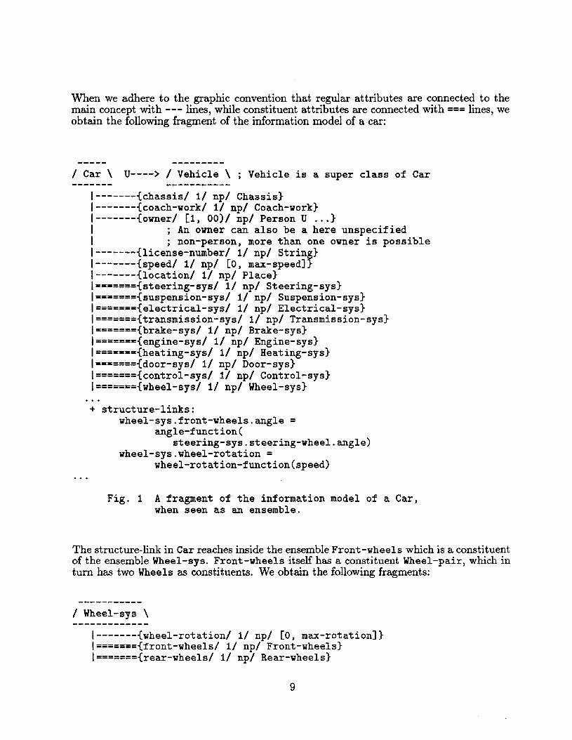
When we adhere to the graphic convention that regular attributes are connected to themain concept with --- lines, while constituent attributes are connected with === lines, weobtain the following fragment of the information model of a car:
/ Car \ u----> / Vehicle \ ; Vehicle is a super class of Car
-------{chassis/ 1/ np/ Chassis}-------{coach-work/ 1/ np/ Coach-work}-------{owner/ [1, 00)/ np/ Person U ... }
; An owner can also be a here unspecified; non-person, more than one owner is possible
-------{license-number/ 1/ np/ String}-------{speed/ 1/ np/ [0, max-speed]}-------{location/ 1/ np/ Place}======={steering-sys/ 1/ np/ Steering-sys}======={suspension-sys/ 1/ np/ Suspension-sys}======={electrical-sys/ 1/ np/ Electrical-sys}======={transmission-sys/ 1/ np/ Transmission-sys}======={brake-sys/ 1/ np/ Brake-sys}======={engine-sys/ 1/ np/ Engine-sys}======={heating-sys/ 1/ np/ Heating-sys}======={door-sys/ 1/ np/ Door-sys}======={control-sys/ 1/ np/ Control-sys}======={wheel-sys/ 1/ np/ Wheel-sys}
+ structure-links:wheel-sys.front-wheels.angle =
angle-function (steering-sys.steering-wheel.angle)
wheel-sys.wheel-rotation =wheel-rotation-function(speed)
Fig. 1 A fragment of the information model of a Car,when seen as an ensemble.
The structure-link in Car reaches inside the ensemble Front-wheels which is a constituentof the ensemble Wheel-sys. Front-wheels itself has a constituent Wheel-pair, which inturn has two Wheels as constituents. We obtain the following fragments:
/ Wheel-sys \
I-------{wheel-rotation/ 1/ np/ [0, max-rotation]}I======={front-wheels/ 1/ np/ Front-wheels}I======={rear-wheels/ 1/ np/ Rear-wheels}
9

1 Front-wheels \
I-------{anglel 11 npl [0, max-angle]}I======={wheel-pairl 11 npl Wheel-pair}
1 Rear-wheels \
I======={differential-gear-sysl 11 npl Differential-gear}I======={wheel-pairl 11 npl Wheel-pair}
1 Wheel-pair \
I======={left-wheell 11 npl Wheel}I======={right-wheell 11 npl Wheel}
Fig. 2 A fragment of some constituents of theensemble Car; these constituents arethemselves ensembles.
Regular attributes and constituent attributes have much in common, see section 2. Aconstituent attribute also has a cardinality descriptor, a modality descriptor as well as acharacterization of the value restriction, i.e. the kind of constituent(s) that is referred toin the attribute. For example, if we see the wheels of a Car as non-distinguished subconstituents of the Wheel-sys constituent - unlike the modeling done above -, we canindicate that the cardinality feature is four (excluding here pathological vehicles), that themodality is necessary and that the kind is obviously Wheel. A structure link capturing aninvariant can refer to a constituent attribute as well. For example, there is a constraintbetween the angle of the front wheels with respect to the chassis and the degree of rotationof the steering wheel as expressed above in the information model of Car.
Observe that we introduced a regular attribute wheel-rotation in Wheel-sys. A structurelink in Wheel-sys should express that the value of this attribute is the average of therotations of the Wheels in the two constituting Wheel-pairs.
An ensemble can have a regular state-transition model (and possibly more than one, as isallowed for regular objects). For example, we can observe for our car whether it is insuredor not, whether it is for sale or not, whether the manual transition indicates neutral, rear,first, second, third, fourth gear, whether the lights are off, on park lights, dimmed or full,etc. Some of these state-models are imported from lower level constituents through thecontrol-sys constituent.
As a major difference between an object and an ensemble, we have associated with anensemble a forwarding mechanism for triggers and messages that mediates between externalentities and the constituents of an ensemble. Thus, we can hide aspects of the constituents
10

of an ensemble which have significance only inside the ensemble. For example, the interfaceof the engine is an internal affair of a car and the outside world need not to know anythingabout it. On the other hand, the forwarding mechanism of the car ensemble should exportthe interface of the control constituent.
We will illustrate information hiding occurring within the car ensemble by sketching thedescription of starting a car. We will export through the Control-sys constituent the statetransition diagrams of an Ignition-lock and of an Oil-pressure-indication-lamp,which are both (sub) constituents of Car.
The state-transition diagram of the ignition lock:
Ignition-lock:insert turn-right turn-right/-->--\ /-->--\ /-->--\
no- inserted contact startkey key
\--<--/ \--<--/ \--<--/remove turn-left turn-left
Fig. 3 The exported state-transition diagram of theignition-lock.
The turn-right transition that leads into the contact state triggers the contacted transition in Oil-pressure-indication-lamp, see below.
Other relevant constituents that we consider are: Start-engine, Engine-sys and Oilpressure-sensor.
Their state transitions will not be exported through the Control-sys. For the start-enginewe have the following behavior description:
Start-engine:start-up/-->--\
off running\--<--/turn-off
Fig. 4 The state-transition diagram of the start-engine.
We assume that the turn-right transition that connects the contact state with the startstate in Ignition-lock has a trigger directed at the start-up transition in Start-engine.(The identity of the recipient object - in this example there is only one legal recipient can be traced through the car ensemble.) We omit here conditions associated with thestart-up transition, like the transmission being in neutral, etc. The start-up transitionin its turn will generate a trigger aimed at the start-up transition in Engine-sys:
11

Engine-sys:start-up/~->--\
off running\--<--/halt
Fig. 5 The state-transition diagram of the engine.
To simplify matters, we assume that the start-up transition in Engine-sys directly triggers the go-high transition in Oil-pressure-sensor:
Oil-pressure-sensor:
go-high/-->--\
low high\--<--/go-low
Fig. 6 The state-transition diagram of theoil-pressure-sensor
The go-high transition finally triggers the start-up transition in:
Oil-pressure-indicator-lamp, which causes the lamp to go off again:
Oil-pressure-indicator-lamp:
contacted start-up/-->--\ /-->--\
lamp lamp lampoff on off
\--<--/ \--<--/not-contacted turn-off
Fig. 7 The exported state-transition diagram of theoil-pressure-indicator-lamp
Since the state-transition of the Oil-pressure-indicator-lamp is exported the driverwill see the lamp go off.
When we look from the outside, we see pseudo causal consequences. For instance, theturn-right transition out of the inserted-key state "causes" the oil-pressure-indicator-lamp to go on. A similar pseudo causality turns this lamp off again when the ignitionlock moves into the start state (which signals the driver to turn the key out of the startposition, which causes the ignition-lock, etc.)
12

However, when we look inside the Car ensemble, we will see a different triggeringj messaging pattern that ultimately achieves these pseudo causal consequences.
In summary and without claim to automotive correctness: starting engine ~ runningengine ~ actual pressure goes up ~ oil pressure sensor goes in high state ~ oil pressurelamp goes off. Consequently, the introduction of ensembles has allowed us to successfullyhide low level mechanisms from higher order functionality.
5 Related work
Object-oriented analysis is a relatively new field. The first book in this area is fromShlaer & Mellor, [9]. Most of the book is devoted to the Information Model. One chapterdiscusses an example in which they illustrate the State Model and their Process Model.Their Process Model differs from ours in that they rely on data flow diagrams, borrowedfrom Structured Analysis, to describe the actions in their State Models. As a result, theinteraction between objects is described in their method in an indirect way - the occurrenceof an external data store in a data flow diagram. We feel that our triggers and messagesallow us to express directly causal interactions between objects. A summary of their versionof Object-Oriented Analysis can be found in [10].
In Ward, [12] , an attempt is made to salvage Structured Analysis and Design when an implementation will be done in an Object-Oriented programming language. Ward acknowledgesthat the original version of SAjSD doesn't lend itself easily to the identification of objects,and certainly not to object hierarchies which deepen the insight in the understanding of thedomain. However, he points to a refinement of SAjSD for real-time systems, [13], in whichentity-relationship modeling is imported from the database realm. We remain doubtfulwhether unbiased object identification can be done after processes have been modeled.
Our comment on Ward's paper, [12], applies also to that of Bailin, [1].
In Wirfs-Brock et al, [14], the authors discuss the notion of a subsystem.
A subsystem is a set of ... classes (and possibly other subsystems) collaboratingto fulfill a common set of responsibilities.
They motivate their subsystems similarly:
Subsystems are a concept used to simplify a design. The complexity of a largeapplication can be dealt with by first identifying subsystems within it, andtreating those subsystems as classes.
They take an explicit position regarding whether subsystems will show up ultimately inan implementation:
Subsystems are only conceptual entities; they do not exist during execution.
13

On the basis of our understanding of their subsystems, we have found here the mostsignificant difference with respect to our ensembles. Certain ensembles introduced in theanalysis phase may indeed be "compiled away" in the subsequent design phase, but weforesee that at least those ensembles which have their own regular attributes in addition toconstituent attributes will show up in the implementation. This explains why we felt thenecessity of introducing a forwarding mechanism for triggers/ messages in ensembles. Inaddition, we surmise that the encapsulation provided by ensembles - constituents cannotbe reached directly from outside an ensemble - is not available in their subsystems.
In the Eurofean terrain, we see two approaches as relevant for the work described here.Jacobson [6 describes a development method for large object-oriented systems, calledObjectOry, that covers the analysis phase as well as the design phase. We discuss hereonly the analysis component. The core notions are: entities, interface objects and use cases.Entities correspond with the objects in the target domain. Interface objects are introducedto shield the "real" objects from the system interface with the users/ external world. Usecases - as far as we understand them - correspond with generic scenarios that define thetarget system's behavior from the perspective of a user. (A user is to be understood ina wide sense; i.e. it can be another system.) The material that we had available didnot mention (sub)systems as a way to structure a target system. Use cases, however, doprovide a global view. We suspect that a use case is a special case of the informationcaptured by a state-transition model associated with the target system represented as anensemble.
Beta [7] is a programming language and also a development technique. The Beta languagesimplifies the collection of object-oriented notions by simply providing patterns as the onlyconcept for classes, methods, procedures and types. As a consequence, the analysis technique reflects this simplicity, and a lot of emphasis is put on modeling the communicationbetween objects. Beta is one of the few object-oriented systems that emphatically supportsconcurrency in all steps of the development process. The Beta concurrency primitives fore.g. synchronization are similar to what we have suggested for triggers and services in ourmethod. The difference is that they have already gained experience with implementinga particular communication scheme, and that they have restricted the analysis to thatscheme (ADA-like rendez-vous). In our technique, the analyst has a degree of freedom todefine and use his/her own communication scheme.
6 Summary and Conclusion
Object-oriented techniques, as practiced in OOP have a bottom-up flavor since OOP doesnot formalize and elaborate object decomposition. This is acceptable or even desirable inthe programming phase. However, an analyst needs to operate - especially in the earlyphase - in a top-down fashion. In this paper, we have proposed ensembles as a mechanismfor clustering tightly coupled objects. This mechanism supports top-down decomposition.We have illustrated ensembles with several examples.
A major distinction between ensembles and objects is that an ensemble connotes an entitywith internal parallelism, while an object connotes - from the perspective of the task domain - a finite state machine. We associate with an ensemble a trigger/ message forwardingmechanism that mediates the interaction between external entities and the internal constituents of the ensemble. The examples discussed indicate that information hiding can beachieved indeed through ensembles.
14
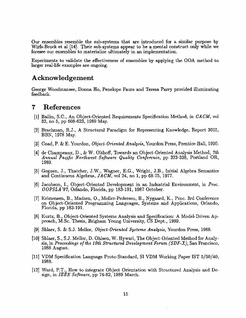
Our ensembles resemble the sub-systems that are introduced for a similar purpose byWirfs-Brock et al [14]. Their sub-systems appear to be a mental construct only while weforesee our ensembles to materialize ultimately in an implementation.
Experiments to validate the effectiveness of ensembles by applying the OOA method tolarger real-life examples are ongoing.
Acknowledgement
George Woodmansee, Donna Ho, Penelope Faure and Teresa Parry provided illuminatingfeedback.
7 References[1] Bailin, S.C., An Object-Oriented Requirements Specification Method, in CACM, vol
32, no 5, pp 608-623, 1989 May.
[2] Brachman, R.J., A Structural Paradigm for Representing Knowledge, Report 3605,BBN, 1978 May.
[3] Coad, P. & E. Yourdon, Object-Oriented Analysis, Yourdon Press, Prentice-Hall, 1990.
[4] de Champeaux, D., & W. Olthoff, Towards an Object-Oriented Analysis Method, 7thAnnual Poeific Northwest Software Quality Conference, pp 323-338, Portland OR,1989.
[5] Goguen, J., Thatcher, J.W., Wagner, E.G., Wright, J.B., Initial Algebra Semanticsand Continuous Algebras, JACM, vol 24, no 1, pp 68-75,1977.
[6] Jacobson, 1., Object-Oriented Development in an Industrial Environment, in Proc.OOPSLA '87, Orlando, Florida, pp 183-191, 1987 October.
[7] Kristensen, B., Madsen, 0., Moller-Pedersen, B., Nygaard, K., Proc. 3rd Conferenceon Object-Oriented Programming Languages, Systems and Applications, Orlando,Florida, pp 183-191.
[8] Kurtz, B., Object-Oriented Systems Analysis and Specification: A Model-Driven Approach, M.Sc. Thesis, Brigham Young University, CS Dept., 1989.
[9] Shlaer, S. & S.J. Mellor, Object-Oriented Systems Analysis, Yourdon Press, 1988.
[10] Shlaer, S., S.J. Mellor, D. Ohlsen, W. Hywari, The Object-Oriented Method for Analysis, in Proceedings of the 10th Structured Development Forum (SDF-X), San Francisco,1988 August.
[11] VDM Specification Language Proto-Standard, SI VDM Working Paper 1ST 5/50/40,1988.
[12] Ward, P.T., How to integrate Object Orientation with Structured Analysis and Design, in IEEE Software, pp 74-82, 1989 March.
15

[13] Ward, P.T. & S.J. Mellor, Structured Development for Real-Time Systems, PrenticeHall, Englewood Cliffs NJ, 1985.
[14] Wirfs-Brock, R.J. & R.E. Johnson, A Survey of Current Research in Object-OrientedDesign, draft of a report of Tektronik Inc, POB 1000, Wilsonville OR 97070.
16