oak to ninth avenue development feasibility … · 5 terminal building substructure (ninth ave...
TRANSCRIPT

OAK TO NINTH AVENUE DEVELOPMENT
FEASIBILITY ANALYSIS FOR SHORELINE IMPROVEMENTS AND PIER RETROFIT
Prepared for:
Prepared by:
Moffatt & Nichol2001 N. Main Street, Suite 360
Walnut Creek, CA 94596
File No. 4942-01
February 5, 2004

OAK TO NINTH AVENUE DEVELOPMENT
FEASIBILITY ANALYSIS FOR SHORELINE IMPROVEMENTS AND PIER RETROFIT TABLE OF CONTENTS 1.0 Introduction...................................................................................................................... 1 1.1 Background .......................................................................................................... 1 1.2 Scope of Work ...................................................................................................... 1 2.0 Environmental Site Conditions......................................................................................... 1 2.1 Water Levels......................................................................................................... 1 2.2 Wave Conditions .................................................................................................. 2 2.3 Wave Runup......................................................................................................... 2 2.4 Wave Overtopping and Crest Elevation ............................................................... 3 3.0 Shoreline Treatment ........................................................................................................ 5 3.1 Segment 1 – Lake Merritt Channel and Estuary Waterfront ................................. 5 3.2 Segment 2 – Wetlands ......................................................................................... 6 3.3 Segment 3 – Clinton Basin ................................................................................... 6 3.4 Segment 4 – Clinton to Ninth Avenue Pier Apron ................................................ 8 3.5 Segment 5 – Ninth Avenue Terminal Wharf ......................................................... 8 3.6 Analysis of Alternatives for Ninth Ave Terminal Pier Retrofit.............................. 10 4.0 Permits .......................................................................................................................... 11
Figures
Appendix A – Memorandum, Existing Shoreline and Wharf Conditions

OAK TO NINTH AVENUE DEVELOPMENT FEASIBILITY ANALYSIS
1
1.0 INTRODUCTION 1.1. Background The Oak to Ninth Avenue project site consists of 60 acres of waterfront property currently owned by the Port of Oakland. It is bounded by Embarcadero to the northeast, Lake Merritt Channel to the northwest and Oakland Estuary to the south. Development plans for the site include mostly residential land uses with open areas located throughout. As part of the redevelopment, the top of bank along the shoreline will be raised and improvements made to accommodate proposed land uses and water-oriented development. 1.2 Scope of Work Moffatt & Nichol provided preliminary engineering for the development of alternatives related to shoreline repair/improvement and seismic retrofit of the Ninth Avenue pier. The work, organized into Shoreline Segments for this study, included an assessment of existing conditions, development of shoreline improvement methods and estimates of construction costs. Conceptual construction costs for the 5th Avenue Marina and Clinton Basin Marina have been estimated for planning purposes. 2.0 ENVIRONMENTAL SITE CONDITIONS 2.1 Water Levels The water levels for the area are characterized as semi-diurnal tides with two unequal highs and lows each lunar day. Using the tidal datums for the station at Park Street Bridge, Oakland Inner Harbor, elevations of tidal datums are shown in Table 1.
TABLE 1 TIDAL DATUMS
Reference Plane Elevation
(Ft, MLLW) (Ft, OCD) Highest Observed Water Level (02/16/1980) 8.47 2.59 Mean Higher High Water (MHHW) 6.44 0.56 Oakland City Datum, OCD 5.88 0.00 Mean High Water (MHW) 5.82 -0.06 Mean Tide Level (MTL) 3.46 -2.42 National Geodetic Vertical Datum, 1929 (NGVD) 2.88 -3.00 Mean Low Water (MLW) 1.09 -4.79 North American Vertical Datum-1988 (NAVD) 0.23 -5.65 Mean Lower Low Water (MLLW) 0.00 -5.88 Lowest Observed Water Level (06/02/1977) -2.07 -7.95

OAK TO NINTH AVENUE DEVELOPMENT FEASIBILITY ANALYSIS
2
Extreme water levels near the project site were used to calculate the worst case overtopping rates. Table 2 includes return period water levels developed by the US Army Corps of Engineers (1984) for the tidal station 4746 (Oakland / Alameda, Park Street Bridge). The 50-year tide level was not published by the Army Corps thus requiring interpolation between the 10 and 100-year values.
TABLE 2 EXTREME WATER LEVELS AND RETURN PERIOD (feet OCD)
Return Period Elevation (Ft.)
10 3.12 50 3.47*
100 3.62 * This is an interpolated number 2.2 Wave Conditions Wave predictions for the site were developed based on a spectral wave hindcasting model. This model incorporates methods described in the Shore Protection Manual (US Army Corps of Engineers, 1984), modified for narrow fetches. The input parameters are adjusted wind speed (wind stress factors), wind duration, fetch length and water depth. Fetch is the length of water body (aligned parallel to wind direction) over which the wind generates waves. The Estuary bottom elevations were estimated at -40 feet OCD based on recent nautical charts. Two possible primary fetch directions were considered: 1) winds primarily from the northwest (NW), which is along the channel, and 2) winds primarily from the southwest (SW), which is across the channel. Results of the wave hindcast analysis for the high tide conditions are presented below.
TABLE 3 WAVE HINDCASTING RESULTS
Wave Conditions* (Hs / Tp) Return Period
(years) Water
Depth (ft) N-W Waves S-W Waves 25 40 1.6 ft / 1.8 sec 1.5 ft / 1.7 sec 50 40 1.8 ft / 1.8 sec 1.6 ft / 1.8 sec
* Hs – Significant Wave Height; Tp – Peak Spectrum Wave Period
2.3 Wave Runup Wave run-up and overtopping calculations allow an objective means for evaluating the level of protection offered by various bank geometries (height, and slope) and armor protection combinations. Run-up calculations determine the expected elevation that waves would reach up a revetment slope, assuming an infinite bank height. The Van der Meer equation (Herbich,

OAK TO NINTH AVENUE DEVELOPMENT FEASIBILITY ANALYSIS
3
2000) was used to provide an estimate of the run-up value along the shoreline. This method is used to estimate R2% (run-up exceeded by the highest 2% of incoming waves). The cross section used for the run-up analyses is shown on the following figure. Three cases of water depths were analyzed (still water elevations of +3.12 feet, +3.47 feet and +3.62 feet OCD, corresponding to 10 year, 25 year and 50 year tide levels), combined with 25- and 50- return period year wave conditions. The slope of the revetment was assumed to be 2H:1V. A slope roughness value of 0.55 was used for the rip-rap layer, assuming 2 layers of armor rock. Waves were assumed to be shore-normal, with heights and periods as listed in Table 4. Two values of run-up are presented below: R2% which is the run-up associated with the highest 2% of the incoming waves and Rm which is the mean wave run-up. The calculated run-up was added to the still water elevation to determine the run-up elevations shown below.
Typical Cross Section Used in Wave Run-Up Analysis
TABLE 4 WAVE RUNUP ELEVATIONS
Wind / Wave Return Period
Storm Water Level
Revetment Slope
Still Water Elev (Ft, OCD)
2% Runup (Ft, OCD)
Mean Runup (Ft, OCD)
10 Year 2:1 +3.1 +5.4 +4.1 50 Year 2:1 +3.5 +5.8 +4.5 25 year 100 Year 2:1 +3.6 +5.9 +4.6 10 Year 2:1 +3.1 +5.5 +4.1 50 Year 2:1 +3.5 +5.9 +4.5 50 year 100 Year 2:1 +3.6 +6.0 +4.6
2.4 Wave Overtopping and Crest Elevation While wave runup is an indication of how high the water level will advance for certain wave conditions, overtopping is a more objective and rational method for estimating the level of wave protection. Specifically, wave overtopping can be used to determine the level of armor
R SWL
Top of Bank
Slope - 2H:1V -40

OAK TO NINTH AVENUE DEVELOPMENT FEASIBILITY ANALYSIS
4
protection on the crest and backslope, and the overtopping rate can be used to assess the level of flood protection afforded with different bank elevations. Overtopping computations were performed for the 10-, 50- and 100-year water levels, with varying top of bank elevations. Results are shown in Table 5. General overtopping rate guidelines are also provided in Table 6 to help interpretation of these overtopping rates.
TABLE 5 OVERTOPPING RATES
Overtopping Rate (cfs/ft) of Bank Wind / Wave
Return Period Storm Water
Level Still Water Elev
(ft, MLLW) 2% Runup (ft, MLLW) 5.1‘ Crest 5.6’ Crest 6.1’ Crest
10 Year +3.1 +5.4 0.0036 0.0007 0.0001 50 Year +3.5 +5.8 0.0111 0.0022 0.0004 25 year 100 Year +3.6 +5.9 0.0181 0.0036 0.0007 10 Year +3.1 +5.5 0.0049 0.0010 0.0002 50 Year +3.5 +5.9 0.0147 0.0031 0.0006 50 year 100 Year +3.6 +6.0 0.0234 0.0049 0.0010
Since the probability of a storm wave and an extreme water level occurring simultaneously is relatively low, the combination of a 50 – year wind and a 10 – year water level was selected for the design condition. The maximum overtopping rate, assuming a crest elevation of +6 feet, is estimated to be 0.0002 cfs/ft.
TABLE 6 OVERTOPPING DISCHARGE THRESHOLDS
Overtopping Rate (cfs/ft of wall)
Impact
0.00004 Person walk immediately behind dike with little discomfort 0.0003 Person walk immediately behind dike with little danger 0.00001 Vehicle to pass immediately behind dike at high speed 0.0002 Vehicle to pass immediately behind dike at low speed 0.00001 House located immediately behind dike to suffer no damage 0.0003 House located immediately behind dike to suffer no structural
damage, although experiencing partial damage to windows and doors 0.02 Dike crown and back slope unprotected to suffer no damage 0.2 Dike crown protected, back slope unprotected to suffer no damage 0.5 Dike crown and back slope protected to suffer no damage

OAK TO NINTH AVENUE DEVELOPMENT FEASIBILITY ANALYSIS
5
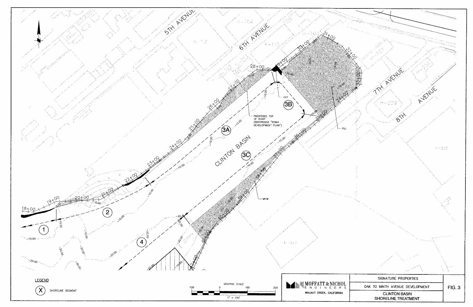
3.0 SHORELINE TREATMENT The shoreline, as discussed in this report, is divided into Segments (1 through 5). The shoreline Segments are defined by Station in Table 7 and shown on Figure 1.
TABLE 7 OAK TO NINTH AVENUE SEGMENTS
Segment
No. Description Begin Station
End Station
1 Lake Merritt Channel and Estuary Waterfront 0+00 19+00 2 Wetlands 19+00 22+50
3a Clinton Basin – North Side 22+50 28+50 3b Clinton Basin – East Side 28+50 35+00* 3c Clinton Basin - South Side 35+00 41+00 4 Clinton to Ninth Ave Pier Apron 41+00 46+75 5 Terminal Building Substructure (Ninth Ave Pier) 46+75 59+00
*Actual length of new wall required for east side of Clinton Basin is 210 feet. Station line is along top of existing bank. The original work on the project divided the shoreline into Reaches. Theses Reaches were used in early documentation and are shown in Appendix A as a part of a memorandum describing the visual inspection effort. The Reaches were changed to shoreline Segments for this report. The shoreline Segments were selected so that each Segment contained shoreline treatment of a similar type. The shoreline work consists of a number of primary elements; shoreline cleanup, shoreline protection (rip-rap, walls), structure demolition, dredging, structure retrofit, and marina construction. 3.1 Shoreline Segment 1 - Lake Merritt Channel and Estuary Waterfront Moffatt & Nichol performed a visual inspection of the shoreline between the Lake Merritt Channel and the Oakland Ninth Avenue Terminal Pier, with the objective of developing recommendations for modifications and/or repairs for the shoreline. The shoreline within the study area varies significantly in this Segment, depending on the past and present uses of the backland area, and ranges from unprotected undulating / eroding banks to cemented (grouted) banks and concrete debris. The embankment near the Lake Merritt Channel is low, and grades may have to be raised depending on planned uses of the area. Our recommendation for Segment 1 is to construct a rip-rap revetment. This will remove undulations, eliminate erosion, and improve the appearance of the shoreline. Armor rock sizes were estimated based on the design wave conditions, described above. We recommend that the levee be armored with 2 layers of Caltrans “Facing Class” rock or larger (nominal weight of 200 lbs).
OAK TO NINTH AVENUE DEVELOPMENT FEASIBILITY ANALYSIS
6
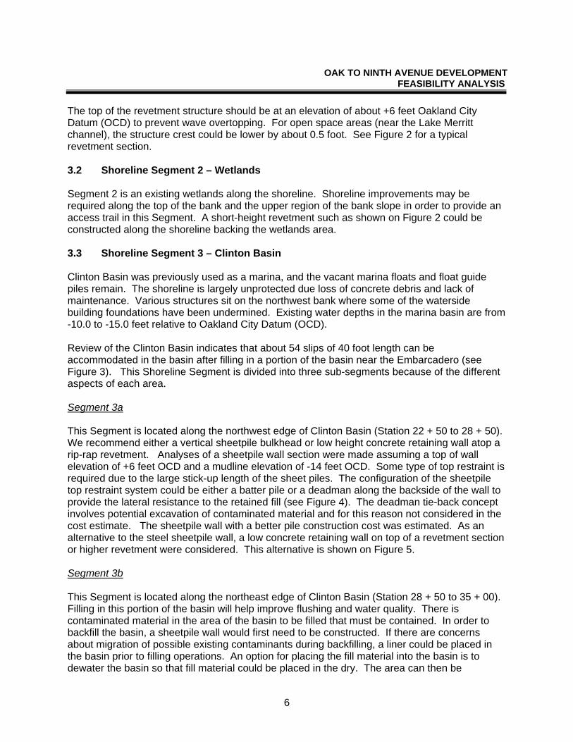
The top of the revetment structure should be at an elevation of about +6 feet Oakland City Datum (OCD) to prevent wave overtopping. For open space areas (near the Lake Merritt channel), the structure crest could be lower by about 0.5 foot. See Figure 2 for a typical revetment section. 3.2 Shoreline Segment 2 – Wetlands Segment 2 is an existing wetlands along the shoreline. Shoreline improvements may be required along the top of the bank and the upper region of the bank slope in order to provide an access trail in this Segment. A short-height revetment such as shown on Figure 2 could be constructed along the shoreline backing the wetlands area. 3.3 Shoreline Segment 3 – Clinton Basin Clinton Basin was previously used as a marina, and the vacant marina floats and float guide piles remain. The shoreline is largely unprotected due loss of concrete debris and lack of maintenance. Various structures sit on the northwest bank where some of the waterside building foundations have been undermined. Existing water depths in the marina basin are from -10.0 to -15.0 feet relative to Oakland City Datum (OCD). Review of the Clinton Basin indicates that about 54 slips of 40 foot length can be accommodated in the basin after filling in a portion of the basin near the Embarcadero (see Figure 3). This Shoreline Segment is divided into three sub-segments because of the different aspects of each area. Segment 3a This Segment is located along the northwest edge of Clinton Basin (Station 22 + 50 to 28 + 50). We recommend either a vertical sheetpile bulkhead or low height concrete retaining wall atop a rip-rap revetment. Analyses of a sheetpile wall section were made assuming a top of wall elevation of +6 feet OCD and a mudline elevation of -14 feet OCD. Some type of top restraint is required due to the large stick-up length of the sheet piles. The configuration of the sheetpile top restraint system could be either a batter pile or a deadman along the backside of the wall to provide the lateral resistance to the retained fill (see Figure 4). The deadman tie-back concept involves potential excavation of contaminated material and for this reason not considered in the cost estimate. The sheetpile wall with a better pile construction cost was estimated. As an alternative to the steel sheetpile wall, a low concrete retaining wall on top of a revetment section or higher revetment were considered. This alternative is shown on Figure 5. Segment 3b This Segment is located along the northeast edge of Clinton Basin (Station 28 + 50 to 35 + 00). Filling in this portion of the basin will help improve flushing and water quality. There is contaminated material in the area of the basin to be filled that must be contained. In order to backfill the basin, a sheetpile wall would first need to be constructed. If there are concerns about migration of possible existing contaminants during backfilling, a liner could be placed in the basin prior to filling operations. An option for placing the fill material into the basin is to dewater the basin so that fill material could be placed in the dry. The area can then be

OAK TO NINTH AVENUE DEVELOPMENT FEASIBILITY ANALYSIS
7
backfilled by either dragline operations if adjacent material is to be used, or dumping and spreading if fill material must be brought to the site. We recommend a sheetpile wall restrained at the top by tie-backs, similar to Segment 3a. The sheetpiles would isolate the soils in the basin during backfilling operations, then remain in place as the final shoreline treatment. Or, as an alternative to sheetpile wall shoreline treatment in Segment 3b, a rip-rap revetment with short retaining wall, similar to Segment 3a may be utilized. Containment of contaminated fills with such a treatment may be less effective. Dredging Dredging will be required in order to provide adequate water depth for the berthing area in Clinton Basin. For a design water depth of 8 feet at a tide level of Mean Lower Low Water, the basin would be dredged to about Elevation –14 feet OCD. Disposal options would be dependent on the quality of the sediments to be removed. If the basin is dredged utilizing a hydraulic cutterhead dredge, the dredged material would be hydraulically pumped into a settling pond constructed on the site. The solids would settle to the bottom of the pond and the free water would be decanted and discharged back into the Estuary. If water quality is an issue due to possible sediment contaminants, the decanted water may require other treatments before the disposition of the water is determined. A second type of dredging method that could potentially be used is a mechanical dredge. This will consist of a small crane or an excavator mounted on a shallow draft barge. The mechanical dredge would use a bucket to excavate the material from the marina bottom. The dredged material would then be placed into small scows or onto shallow draft barges and transported to an offload location adjacent to a settling pond. The dredged material would then be removed from the scow or barge utilizing the crane or excavator and placed into the settling ponds. If the settling ponds are located away from the waterfront area where the scows or barges could not be directly offloaded into the settling ponds, an alternative pump-out facility could be used. The pump-out facility would consist of an anchored float or barge with a feedwater pump to slurry the material in the scow, and a dredge pump to transport the slurry from the scow to the disposal site. The scow would be emptied and then cycled back to the mechanical dredge to be filled again. If this dredged material is placed into the settling ponds with mechanical cranes or excavators, the amount of water in the settling ponds is less than that generated from hydraulic dredging. Segment 3c Segment 3c is along the southeast edge of Clinton Basin (Station 35 + 00 to 41 + 00). We recommend the same treatment here as Segment 3a (either a sheetpile wall with tie-backs or a rip-rap revetment with short retaining wall).

OAK TO NINTH AVENUE DEVELOPMENT FEASIBILITY ANALYSIS
8
3.4 Segment 4 – Clinton to Ninth Avenue Pier Apron Timber Wharf Apron Segment 4 Shoreline is a timber wharf located between Clinton Basin and the Ninth Avenue Terminal. The wharf was constructed in the 1940s and originally designed for heavy vertical loads. The majority of the vertical piles have been PVC wrapped within the last 20 years. Although Moffatt & Nichol did not remove the wrappings to inspect the piles, at least some of the piles appear competent and capable of supporting light traffic loads and a pathway based on hammer soundings. The batter piles and some of the fender piles (both unwrapped) have lost all or majority of their cross sectional area at the waterline due to marine borer attack. Several piles in the Clinton Basin corner pile cluster are cracked – most probably due to ship impact. The asphalt deck is badly cracked, pot-holed, and in need of repair or replacement. The original lateral force resisting system consisted of exterior batter piles combined with connection of the pilecaps to the bulkhead. None of the batter piles have any lateral load resisting capacity due to loss of section at the waterline. As a result, the apron relies on the lateral capacity of the vertical timber piles (acting as cantilever) and the connection of the pile caps to the bulkhead wall to resist seismic forces. We anticipate that pile bending stress under current seismic loading requirements would significantly exceed the allowable values. As a number of the piles appear to be of the original 1940’s construction, we anticipate that a significant number of piles would require replacement should the wharf be retained. Although wharf repairs for this timber structure are possible, it is our opinion that the number of piles requiring replacement may be significant and costly. We assume that this timber wharf will be demolished, not replaced. If planned uses for the site require the area provided by the existing deck, then we recommend demolishing the existing timber wharf and rebuilding a concrete wharf. Concrete Bulkhead The timber wharf structure frames into a cast-in-place concrete bulkhead parallel to the face of the wharf. The toe of the wall is protected by stone rip-rap. The concrete bulkhead appears to be in good condition. The rip-rap toe protection is also in good condition and covers the base of the bulkhead wall. We recommend leaving this bulkhead in place and placing additional rip-rap in the wave splash zone. See Figure 6 for a typical section of the added rock to the toe of the existing structure. 3.5 Segment 5 – Ninth Avenue Terminal Pier The Ninth Avenue Terminal Pier is a 1200–foot long wharf, originally constructed in 1930 with a total area of about 270,000 square feet. In the late 1930’s, the pier was extended to include apron areas to the north and west of the 1930 structure (Segment 4). The aprons are of timber construction, with timber piles/pilecap and deck. The pier structure for the Ninth Avenue Terminal building is composed of a concrete deck supported by jacketed concrete and green timber (non-creosoted) piles. There are a total of approximately 4300 piles (timber, concrete, and jacketed green timber) piles supporting the deck.

OAK TO NINTH AVENUE DEVELOPMENT FEASIBILITY ANALYSIS
9
As a part of Moffatt & Nichol’s effort to evaluate the need for additional shear reinforcement required at the pile/cap connection, a pile strain demand analysis was performed. This analysis was performed on a typical concrete sleeve and typical timber pile with a limited free sub-floor clearance of 5 feet from the soffit of the deck slab to the top of mud. The maximum concrete sleeve strains for an 8-inch displacement were found to be less than 0.4%, which is close to the spalling limit of unconfined concrete. The timber pile section experiences a maximum strain level of less than 0.5% which appears to be close to the extreme strain capacity for timber. The results of this analysis work formed the basis for selecting retrofit methods. In an effort to reduce the cost to retrofit the wharf, Moffatt & Nichol investigated several alternatives. Two of these alternatives increase the piles ductility by pile wrapping, one alternative is to rebuild the wharf altogether and one alternative is to provide ballasted crib (bins) structure along the back inside edge of the wharf to limit displacements. These alternatives are described more fully below. All retrofit alternatives include removing the 16 foot wide timber apron along the wharf face. This apron is in poor condition and would therefore be a high maintenance feature of the project. Also, the timber wharf along the west end of the wharf was also assumed removed in all alternatives. As with the timber apron, this structure requires demolition due to its poor condition. In all cases, the 250 foot long timber railroad trestle at the east end of the wharf is to be removed.
Alternatives 1 & 1A - Retrofit Concrete Wharf, Replace Timber Apron (Figures 7 and 11)
Alternative 1 requires wrapping the upper portion of all existing piles with a fiberglass material. Alternative 1A is the same as Alternative 1 except that it provides for a step down at the outboard edge of the wharf. This step requires removing 12 feet of deck along the edge, cutting the piles and recoating a new, lower level deck. Alternative 2 - Retrofit With Retained Fill (Figures 8 and 12)
The concrete deck behind the mean high water line or proposed new top of bank would be removed. The piles within this deck area would remain, but not retrofitted. All other existing piles to remain would be wrapped as for Alternative 1. A new retaining wall or cutoff wall fixed to the deck would retain the soil on the inboard edge.
Alternative 3 - New Structure (Figures 9 and 12)
Removal of the existing structure and construction of a new concrete wharf would serve as a “budgetary check” for planning purposes (i.e. retrofit versus replacement). Based on experience with similar work, we have developed an alternative wharf that satisfies the functional and loading requirements for public access. Alternative 4 - Crib Structure (Figures 10 and 13) This alternative involves the construction of a crib structure with deck along the inside edge of the wharf. The crib would act like an anchor, minimizing the displacement of the pier during a seismic event. Work would include demolishing the deck along the inside edge of the wharf, leaving the existing piles in-place (un-retrofitted), constructing the crib structure

OAK TO NINTH AVENUE DEVELOPMENT FEASIBILITY ANALYSIS
10
with backfill, then closing the crib with a deck. The demolished concrete cap is assumed to be used for part of this backfill. A topping slab would extend across the existing deck that remains to tie the existing pier structure to the new crib structure.
3.6 Analysis of Alternatives for Ninth Ave Terminal Pier Retrofit Alternatives 1, 1A and 2 Pile analyses were performed for Alternatives 1 and 2 to confirm the viability of this retrofit approach and also to determine what percent of the piles need to be retrofitted. Using pile displacement capacity as the limiting criteria, a representative frame section of the pier was used to determine the seismic demands on the conceptual retrofit design. A seismic response spectrum, representing a Magnitude 7.25 ± 0.25 earthquake, was modified for near-source effects and an assumed damping ratio of 10% and applied to the frame model. The resulting displacement demand on the frame model was compared to the displacement capacity of the piles to determine if the conceptual retrofit is viable. The prevention of collapse was assumed as the limiting criteria for displacement capacity. Results indicate that, during a seismic event, the maximum pile displacement is about 14.5 inches. The resultant strain in the piles would cause significant damage to the existing (unretrofitted) piles. The lightly reinforced concrete sleeves that fit over both the concrete and green timber piles are known to behave poorly in seismic events. Piles constructed in the 20’s and 30’s used very light confining steel; consequently these piles behave in a non-ductile manner which can induce brittle behavior in the pile section. The solution for this behavior is to confine the concrete by means of a fiber wrap, forcing the cover and core concrete to behave in a ductile manner (see Figure 14). To prevent the pile from shearing at the connection to the capital, a steel dowel is drilled and grouted (or epoxied) from the deck into the pile. The result of these retrofits is that the pile is forced to behave in a ductile manner at the pilehead (top of pile). This increase in ductility will allow increased deflections at the pilehead before the pile collapses. The pile wrapping utilized in Alternatives 1, 1A and 2 increases the ductility of the piles sufficiently to satisfy the seismic displacement demand (14.5 inches). All of the piles supporting the deck must be wrapped. Alternative 3 This alternative is a rebuild of the existing wharf. The section shown on Figure 11 was developed from a recent project having similar seismic demands. Alternative 4 This alternative limits displacement demand in the wharf by placing ballasted cribs or bins along the back inside edge of the wharf. Seismic forces are transmitted to the ballasted cribs through the deck structure. By ballasting the backside of the wharf, displacement at the existing piles will be limited to less than 8.5 inches. No retrofit of the existing piles is required.

OAK TO NINTH AVENUE DEVELOPMENT FEASIBILITY ANALYSIS
11
4.0 PERMITS To describe the development for regulatory agencies such as the US Army Corps of Engineers and San Francisco Bay Conservation and Development Commission (BCDC), the project is described in terms of Bay Fill. Along the shoreline, the Bay is defined as the area bayward of the mean high water contour. A summary of areas to be filled or cut along the shoreline is presented in Table 8.
TABLE 8 FILL AND CUT AREAS - SUMMARY
Description Fill Area
(SF) Cut Area
(SF) Net (SF)
Lake Merritt Channel and Estuary Waterfront (Segment 1) - Revetment
2,484
-7,943
-5,459
Clinton Basin – Vertical Wall Segment 3a (North edge) Segment 3b (East edge) Segment 3c (South edge) Net Total Clinton Basin (Segment 3)
10,123 46,170 18,311
-455 -522
0
9,668
45,648 18,311
73,627
Ninth Avenue Terminal Wharf (Segments 4 and 5) Segment 4 (Remove timber apron) Segment 5 (Remove outboard timber edge, Alt 1)*
0 15,640
-120,579 -15,640
-120,579 0
Net Total Ninth Avenue Terminal Wharf -120,579 TOTAL 92,728 -145,139 -52,411 *For Alternative 1A, the removal of the outboard 16 ft. timber edge is 28 feet wide, which is equal to the removal of 23,512 sf.

OAK TO NINTH AVENUE DEVELOPMENT FEASIBILITY ANALYSIS
FIGURES


OAK TO NINTH AVENUE DEVELOPMENT FEASIBILITY ANALYSIS
APPENDIX A
MEMORANDUM, EXISTING SHORELINE & WHARF CONDITIONS

MEMORANDUM
To: Stan Burns, M&N Oakland From: Dilip Trivedi & Jim Brady Date: February 20, 2002 Subj: Existing Shoreline and Wharf Conditions Signature Properties - Oak to Ninth Street Development M&N File No: 4942 This memo documents our site visit on Tuesday, February 12, 2002. We performed a brief visual inspection of the shoreline between the Lake Merritt Channel and the Oakland 9th Avenue Terminal, and the underside of the timber portion of the 9th Avenue Wharf. We performed the inspection by water (between 1:30 PM and 5:30 PM) using a 12-foot aluminum boat. Following the water side inspection, we looked at the condition of the timber-pile supported deck from above. This was a brief and qualitative assessment of existing conditions, to assist other members on the team who are preparing development concepts for the area. We are continuing our assessment, with the objective of developing recommendations for modifications and/or repairs for the shoreline and the timber portion of the wharf. SHORELINE CONDITIONS Description The shoreline within the study reach ranges from unprotected eroding banks to cemented (grouted) banks, depending on the past and present uses of the backland area. For evaluation purposes, the study reach was divided into six (6) separate segments represented by the different shoreline conditions. The limits of each reach are presented in Figure 1, which is a site plan provided by BKF. Photographs taken during the site visit, for each reach, are presented in Appendix 1. The order of inspection and the write-up presented below proceeded from Reach 1 to Reach 6 (Lake Merritt Channel to Ninth Avenue wharf). Condition Assessment 1. Reach 1 – Lake Merritt Channel to Cement Plant
The shoreline in this reach is characterized by unprotected banks, which are in various stages of erosion. The bank from under the Embarcadero roadway up to the ramp is actively eroding. Slopes range from 4H:1V for the inter-tidal portion, to 1.5H:1V for the embankment section above high water. The east bank along the Lake Merritt channel is relatively flat in the inter-tidal portion, with a low embankment height. The crest of the embankment is at an elevation varying between 8 and 10 feet above Mean Lower Low Water (MLLW), which implies that the embankment could probably get overtopped during high spring tides. A 2 - 3 foot high
MOFFATT & NICHOL ENGINEERS 3000 Citrus Circle, Ste 230, Walnut Creek, CA 94598 Ph: 925-944-5411 ; Fx: 925-944-4732 e-mail : [email protected]

Existing Site & Wharf Conditions Signature Properties – Oak to Ninth Street Development February 20, 2002
P:\4942 Signature-Oak to Ninth\Rpt\Mmo_SiteVisit.doc
berm has been constructed recently at the crest of the embankment, and a silt fence has been installed behind the berm for run-off control.
The berm continues around the end of the promontory, where the channel enters the Estuary, and concrete abutments and other debris is visible between low to mid tide levels. A low-lying depression (drainage swale ?) exists near the end of Reach 1, and the silt fence is set back about 100 feet inland from the shoreline.
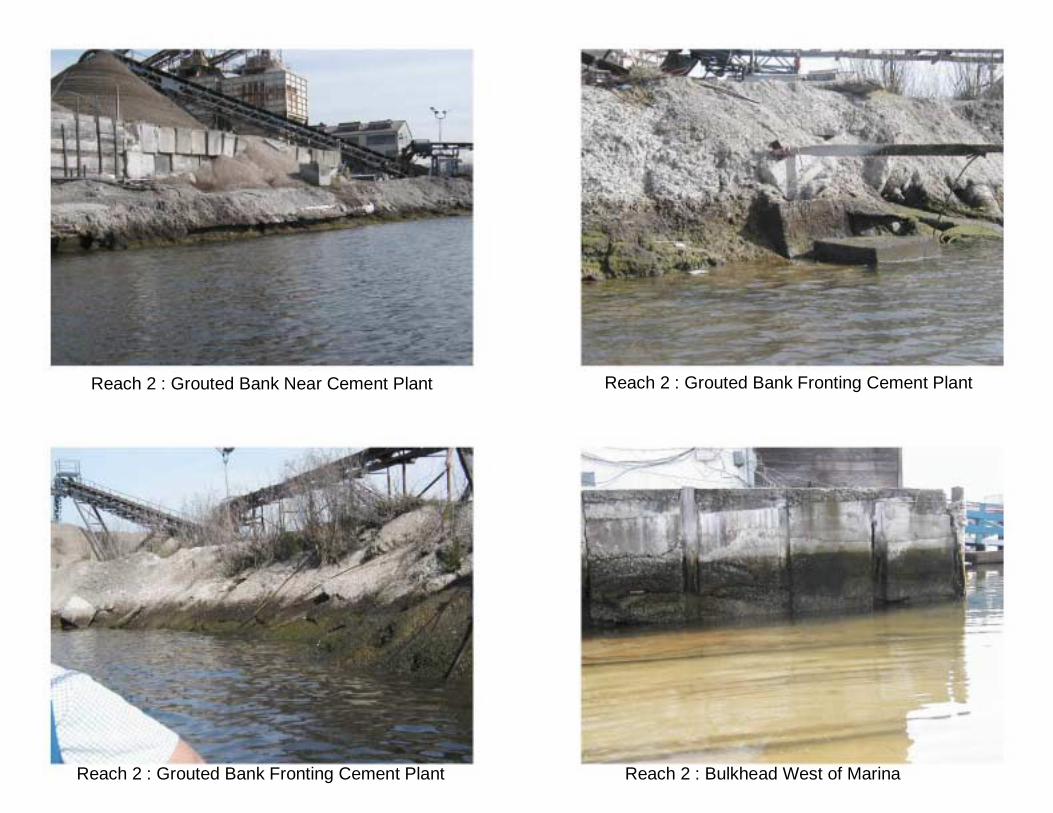
2. Reach 2 – Cement Plant to Marina
The shoreline fronting the cement plant is characterized by cemented grout, probably from the plant itself. Settlement of the bank is apparent, from the cracks that are visible at low tide. Blocks of concrete were also visible below low tide, near the toe of the cemented bank. Near the end of Reach 2 (near the marina) is a cast-in-place concrete bulkhead. Several structures are located close to the bulkhead in this area.
3. Reach 3 – Marina to Mouth of Clinton Basin
The concrete bulkhead wall from Reach 2 continues for a short section near the gangways to both walkways of the marina. The rest of the shoreline is characterized by large concrete blocks / slabs and other debris. Some of the debris has been placed recently, suggesting that settlement and erosion is ongoing.
4. Reach 4 – Mouth of Clinton Basin - West Bank
This reach is characterized by concrete debris, albeit smaller than the debris along Reach 3, and 2 sandy pocket beaches. Ongoing sedimentation in this reach, and possibly storm water, is sustaining vegetation in the form of marsh grasses. The beaches were being used by locals to access the water via rubber dinghies.
5. Reach 5 – Clinton Basin
Several of the floats near the entrance to the basin have been removed, and the west walkway is shorter than that shown on Figure 1. The west bank of the basin is characterized by small concrete debris and cobble up to the first gangway to the floats. Farther into the basin, the bank is unprotected, and several pile-supported structures encroach onto the shoreline.
At the head of the basin (near the Embarcadero) the slope is fairly constant at about 2H:1V to 3H:1V. Sedimentation is evident in this area, as is a low flushing rate by the amount of floating debris that has collected here. The adjacent areas, atop the embankments, are being used for open storage of heavy construction material. The bank has sluffed in this area, probably from run-off induced erosion.
The east bank of the basin is characterized by old concrete abutments and other pile-supported structures.
The decking on the walkways and docks themselves is a mix of timber and concrete, which indicates several modifications have been implemented since construction. The floats at the end of several fingers have lost their buoyancy. The east walkway is in generally

Existing Site & Wharf Conditions Signature Properties – Oak to Ninth Street Development February 20, 2002
P:\4942 Signature-Oak to Ninth\Rpt\Mmo_SiteVisit.doc
poorer conditions than the west walkway. The condition of the piles and other structural aspects of the docks were not evaluated during this site visit, and will be assessed after our next team meeting.
NINTH AVENUE TERMINAL WHARF Description The timber wharf structure is more than 50 years old and abuts the concrete wharf structure that supports the 9th Avenue Terminal. The attached Port of Oakland drawings dated December 1976 describe a pile replacement program. The wharf is made up of timber plumb piles, timber pilecaps, stringers and decking. An asphalt concrete topping slab covers the timber decking. Timber fender piles protect the waterside edge of the wharf. Just behind the fender piles are batter piles. In total there are over 1,000 vertical piles. I assume that this is the last pile replacement program undertaken. The majority of the plumb piles are PVC wrapped. About 5% of the plumb piles are encased in concrete. All of the timber piles except for the batter piles are either PVC wrapped or encased in concrete. The most recent pile replacement program appears to have been done in 1977 Condition Assessment 1. Piles
The vertical piles are either PVC wrapped or encased in concrete (more than 90% are wrapped). The PVC wrappings are in good condition – only a few holes were noted. I pounded several wrapped piles at about +2.5 above Mean Lower Low Water. No softness was detected. Generally the vertical piles appear competent and capable of supporting the design deck loadings.
The fender piles and batter piles were never PVC wrapped. All of the batter piles have rotted to the point of complete separation at the waterline. Some of the fender piles are similarly separated at the waterline. The concrete piles that frame the firewall at line 25 appear to be in good condition. The firewall has had several panels either removed or broken out. Several piles in the Clinton Basin corner pile cluster are cracked – most probably due a ship impact.
2. Concrete Bulkhead
The timber wharf structure frames into a cast-in-place concrete bulkhead. The toe of the wall is protected by stone rip-rap. The concrete bulkhead appeared to be in good condition. The rip-rap toe protection is also in good condition and covers the base of the bulkhead wall
3. Firewall at Frame Line 22
A concrete firewall is located at Frame Line 22. This is supported by 11 concrete piles and 4 timber piles. The firewall is missing between the timber pile sections. Between the concrete piles the firewall is in good condition.

Existing Site & Wharf Conditions Signature Properties – Oak to Ninth Street Development February 20, 2002
P:\4942 Signature-Oak to Ninth\Rpt\Mmo_SiteVisit.doc
4. Pilecaps, Stringers and Decking
The deck consists of 12” by 14” pilecaps, 4” by 12” stringers and 4” by 12” (?) decking. We observed the condition of a small number of pilecaps and stringers from the water. We were unable to observe the condition of the decking. The pilecaps and stringers appear to be in good condition.
5. Fire Protection System
The underside of the deck is protected by a sprinkler system that extends from the bulkhead out to the fender line. The firewater main is an approximately 12 “ diameter iron pipe attached to the bulkhead wall. The sprinkler lines are approximately 2” diameter black iron pipes. The firewater main is somewhat corroded. The sprinkler lines are in good condition. The fire protection system appears to be functional.
6. Asphalt Deck
We looked at a section of the asphalt deck presently being used by General Construction. The asphalt is heavily cracked and in poor condition.
CONCLUSIONS Shoreline The shoreline in the study area varies significantly by reach, with the predominant bank protection being concrete debris. For the potential future development scenarios discussed at the last team meeting, proposed bank protection schemes would be primarily quarrystone rip-rap and sheet-pile bulkhead. A hydrographic survey of the area is necessary prior to any additional assessment. Demolition and clearing costs are expected to be significant, and should be factored into the design of the appropriate structure, including possible reuse of some of the concrete debris in the development alternatives. The embankment in Reach 1 is low, and grades will have to be raised in this area. It would be appropriate to include some pocket beaches into the shoreline plan, especially near the mouth of Clinton Basin. We recommend that the undulations in the shoreline within Clinton Basin be removed, by “straightening” it via rip-rap or bulkhead structures. This would reduce some of the concerns related to sedimentation and debris collection, by increasing flushing. Permitting constraints will significantly influence the selection of the structure, but we believe that the potential exists to minimize Bayfill by considering the project in its entirety. Wharf The wharf was originally designed for heavy vertical loads. Without performing further testing and analysis it is safe to say that the condition of the vertical load carrying system of piles, pilecaps and stringers is good and capable of supporting light traffic loads and a pathway. Further testing, inspection and analysis may justify heavy truck traffic or vertical live loading in excess of 250 psf. The condition of the decking should be verified prior to permitting heavy loading. The asphalt deck requires replacement.
Existing Site & Wharf Conditions Signature Properties – Oak to Ninth Street Development February 20, 2002
P:\4942 Signature-Oak to Ninth\Rpt\Mmo_SiteVisit.doc
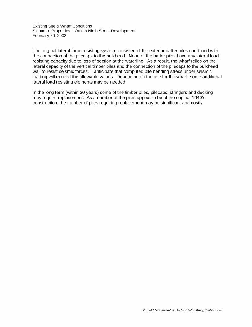
The original lateral force resisting system consisted of the exterior batter piles combined with the connection of the pilecaps to the bulkhead. None of the batter piles have any lateral load resisting capacity due to loss of section at the waterline. As a result, the wharf relies on the lateral capacity of the vertical timber piles and the connection of the pilecaps to the bulkhead wall to resist seismic forces. I anticipate that computed pile bending stress under seismic loading will exceed the allowable values. Depending on the use for the wharf, some additional lateral load resisting elements may be needed. In the long term (within 20 years) some of the timber piles, pilecaps, stringers and decking may require replacement. As a number of the piles appear to be of the original 1940’s construction, the number of piles requiring replacement may be significant and costly.


Reach 1 : Under Embarcadero Bridge Reach 1 : Under Embarcadero Bridge
Reach 1 : East Bank - Lake Merritt ChannelReach 1 : Under Ramp

Reach 1 : East Bank - Lake Merritt Channel Reach 1 : East Bank - Lake Merritt Channel
Reach 1 : Swale West of Cement PlantReach 1 : Old Abutments With Concrete Debris
Reach 2 : Grouted Bank Near Cement Plant Reach 2 : Grouted Bank Fronting Cement Plant
Reach 2 : Bulkhead West of MarinaReach 2 : Grouted Bank Fronting Cement Plant

Reach 3 : Concrete Debris East of Marina
Reach 3 : Concrete DebrisReach 3 : Large Concrete Debris
Reach 3 : Concrete Debris East of Marina
Reach 4 : Beach Near Mouth of Clinton Basin Reach 4 : West Bank - Clinton Basin
Reach 4 : Beach At Mouth of Clinton BasinReach 4 : West Bank - Clinton Basin
Reach 5 : West Bank - Clinton Basin Reach 5 : West Bank - Clinton Basin
Reach 5 : Head of Clinton BasinReach 5 : West Bank - Clinton Basin, Near Head of Basin

Reach 5 : East Bank - Clinton Basin
Reach 5 : Head of Clinton Basin
Reach 5 : East Bank - Clinton Basin

Reach 5 : West Walkway - Clinton Basin Reach 5 : West Walkway - Clinton Basin
Reach 5 : East Walkway - Clinton BasinReach 5 : Walkway Near Head of Clinton Basin