nys-114 installation of empty and load valves€¦ · rail vehicle systems
TRANSCRIPT

R a i l V e h i c l e S y s t e m s
NYS-114 Rev 07 07-22-2016 - en
Service Instructions Installation of EL-60, EL-60/i and EL-60/i-LP Empty and Load Valve

Service Instructions Installation of Empty & Load Valves Doc.-No.: NYS-114
Revision: 07 07/22/16 - en
Copyright 2016© New York Air Brake AG. All rights reserved, including industrial property rights applications. New York Air Brake AG retains any power of disposal, such as copying and transferring.
Page 2 / 12
Contact Address
New York Air Brake
748 Starbuck Avenue
Watertown, NY 13601
USA
Phone: +1 315 786 5200
Fax: +1 315 786 5676
www.nyab.com
Confidentiality
The information in this document and the document itself, in whole or in part, in any form ("Information") is proprietary and/or confidential property of New York Air Brake, a Knorr Brake company, and its affiliates and its successors and as-signees, who retain and reserve all right, title and interest in this Information in whole or in part and in all forms. This Information is provided to the original recipient only for confidential use, with the understanding that it will not be used in any manner detri-mental to the interests of New York Air Brake, and subject to return on request. Reproduction, transmission, distribution or publication of this Information in any form, in whole or in part, for any purpose without prior written permission of New York Air Brake is strictly prohibited. © Copyright New York Air Brake All rights reserved. CONFIDENTIAL

Service Instructions Installation of Empty & Load Valves Doc.-No.: NYS-114
Revision: 07 07/22/16 - en
Copyright 2016© New York Air Brake AG. All rights reserved, including industrial property rights applications. New York Air Brake AG retains any power of disposal, such as copying and transferring.
Page 3 / 12
Revision History
Rev Date Name Para Description of change
01 11/11/99 All Original Issue
02 12/08/03 C Rewritten
03 10/06/04 C-1
C-3 chart
Added note.
Added measurements.
04 10/20/04 B Revised reservoir sizes
05 11/10/04 D Added section
06 06/04/07 All Added EL-60/i-LP
07 07/22/16 C
D
Changed instructions for new cars; added Note regarding stenciling.
Removed section.
The original document was issued in English language.

Service Instructions Installation of Empty & Load Valves Doc.-No.: NYS-114
Revision: 07 07/22/16 - en
Copyright 2016© New York Air Brake AG. All rights reserved, including industrial property rights applications. New York Air Brake AG retains any power of disposal, such as copying and transferring.
Page 4 / 12
Table of Contents
1 General Information 5
2 Safety Awareness 7
3 Tools Required 8
4 Adhesives, Lubricants, Sealants, Solvents 8
5 Types of Installation 9
6 Post-Installation Adjustment 10
7 Supporting Information 11
Service Instructions Installation of Empty & Load Valves Doc.-No.: NYS-114
Revision: 07 07/22/16 - en
Copyright 2016© New York Air Brake AG. All rights reserved, including industrial property rights applications. New York Air Brake AG retains any power of disposal, such as copying and transferring.
Page 5 / 12
1 General Information
1.1 Introduction This document provides instructions for the installation of the EL-60, EL-60/i and EL-60/i-LP Empty and Load Valves.
1.2 Technical Changes
New York Air Brake reserves the right to change this document at any time without giving special notice.
1.3 Target Group This document is intended for use by maintenance personnel who:
Have the skill, experience, safety awareness and professional ability to
- Perform repairs for railroad operations
- Inspect and gauge critical components
Have read and understand this document in its entirety
Are familiar with the safety codes and accident prevention regulations for these activities.
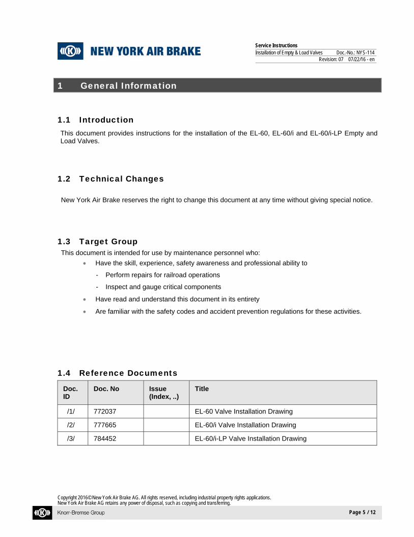
1.4 Reference Documents
Doc. ID
Doc. No Issue (Index, ..)
Title
/1/ 772037 EL-60 Valve Installation Drawing
/2/ 777665 EL-60/i Valve Installation Drawing
/3/ 784452 EL-60/i-LP Valve Installation Drawing
Service Instructions Installation of Empty & Load Valves Doc.-No.: NYS-114
Revision: 07 07/22/16 - en
Copyright 2016© New York Air Brake AG. All rights reserved, including industrial property rights applications. New York Air Brake AG retains any power of disposal, such as copying and transferring.
Page 6 / 12
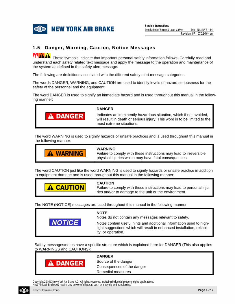
1.5 Danger, Warning, Caution, Notice Messages
These symbols indicate that important personal safety information follows. Carefully read and understand each safety related text message and apply the message to the operation and maintenance of the system as defined in the safety alert message. The following are definitions associated with the different safety alert message categories. The words DANGER, WARNING, and CAUTION are used to identify levels of hazard seriousness for the safety of the personnel and the equipment. The word DANGER is used to signify an immediate hazard and is used throughout this manual in the follow-ing manner:
DANGER
Indicates an imminently hazardous situation, which if not avoided, will result in death or serious injury. This word is to be limited to the most extreme situations.
The word WARNING is used to signify hazards or unsafe practices and is used throughout this manual in the following manner:
WARNING Failure to comply with these instructions may lead to irreversible physical injuries which may have fatal consequences.
The word CAUTION just like the word WARNING is used to signify hazards or unsafe practice in addition to equipment damage and is used throughout this manual in the following manner:
CAUTION Failure to comply with these instructions may lead to personal inju-ries and/or to damage to the unit or the environment.
The NOTE (NOTICE) messages are used throughout this manual in the following manner:
NOTE Notes do not contain any messages relevant to safety.
Notes contain useful hints and additional information used to high-light suggestions which will result in enhanced installation, reliabil-ity, or operation.
Safety messages/notes have a specific structure which is explained here for DANGER (This also applies to WARNINGS and CAUTIONS):
DANGER Source of the danger Consequences of the danger Remedial measures
Service Instructions Installation of Empty & Load Valves Doc.-No.: NYS-114
Revision: 07 07/22/16 - en
Copyright 2016© New York Air Brake AG. All rights reserved, including industrial property rights applications. New York Air Brake AG retains any power of disposal, such as copying and transferring.
Page 7 / 12
2 Safety Awareness
3.1 General Safety Awareness 3.1.1 Observe all rules and regulations where the equipment is being used. Whenever there is a conflict
between the instructions in this manual and the instructions of the user, the rules and regulations of the user will govern.
3.1.2 De-pressurize air system before loosening connections or components. Before removing any com-ponent from its mountings, the train must be safely parked. To prevent personal injury, all main reservoir, brake supply reservoir, and brake cylinder air pressure on the affected vehicle must be vented.
3.1.3 Equipment may be under constant spring load. When handling, exercise caution and avoid rough handling to prevent damage that may result in the release of the internal spring force causing equipment damage or personal injury.
3.1.4 "Bottled" up air under pressure (even though air supply is cut off) may cause gaskets and/or parti-cles of dirt to become airborne and an increase in sound level when any component part is re-moved from the equipment arrangement. Personal eye and ear protection must be worn and care taken to avoid possible injury when performing any work on these component parts.
3.1.5 The use of an air jet, which must be less than 30 PSI, to blow parts clean or to blow them dry after being cleaned with a solvent will cause particles of dirt and/or droplets of the cleaning solvent to be airborne. These particles and droplets may cause skin and /or eye irritation. Personal eye protec-tion must be worn to protect the eyes from possible injury. When using an air jet do not direct it to-ward another person.
3.1.6 If degreasing fluids are used for cleaning purposes, the current local safety regulations plus the safety precautionary statements of the manufacturer of the cleaning agent must be adhered to. Otherwise, physical harm could result from the inhalation of toxic fumes. Make sure the area is well ventilated when working with materials that produce harmful fumes.
3.1.7 Personal eye protection must be worn when doing any work to protect eyes from possible injury.
3.1.8 Where fasteners removed from the equipment are not satisfactory for reuse, care must be taken to select replacements that match the originals. Mismatched or incorrect fasteners can result in equipment damage or malfunction, or possible personal injury.
3.1.9 To ensure the correct functioning of each component, use only the manufacturers genuine spare parts as replacements.
3.1.10 Follow all DANGERS, WARNINGS, CAUTIONS, and NOTES found throughout this specification. If you must use a work procedure or tool which is not recommended, you must first satisfy yourself that neither your safety, nor your fellow workers safety, nor that of the equipment will be jeopardized by the method selected.
3.1.11 Person(s) performing maintenance and/or operational tasks with the brake system and system components are required to have the appropriate job skill level, as governed by the user.
Service Instructions Installation of Empty & Load Valves Doc.-No.: NYS-114
Revision: 07 07/22/16 - en
Copyright 2016© New York Air Brake AG. All rights reserved, including industrial property rights applications. New York Air Brake AG retains any power of disposal, such as copying and transferring.
Page 8 / 12
3 Tools Required
3.1 Standard Tools
Wrench, open ended, 9/16” (2 required)
Wrench, open ended, 3/8”
4 Adhesives, Lubricants, Sealants, Solvents
N/A
Service Instructions Installation of Empty & Load Valves Doc.-No.: NYS-114
Revision: 07 07/22/16 - en
Copyright 2016© New York Air Brake AG. All rights reserved, including industrial property rights applications. New York Air Brake AG retains any power of disposal, such as copying and transferring.
Page 9 / 12
5 Types of Installation
For detailed installation information reference the following installation drawings:
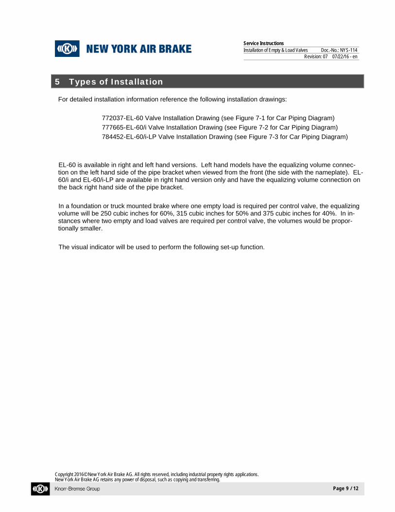
772037 - EL-60 Valve Installation Drawing (see Figure 7-1 for Car Piping Diagram)
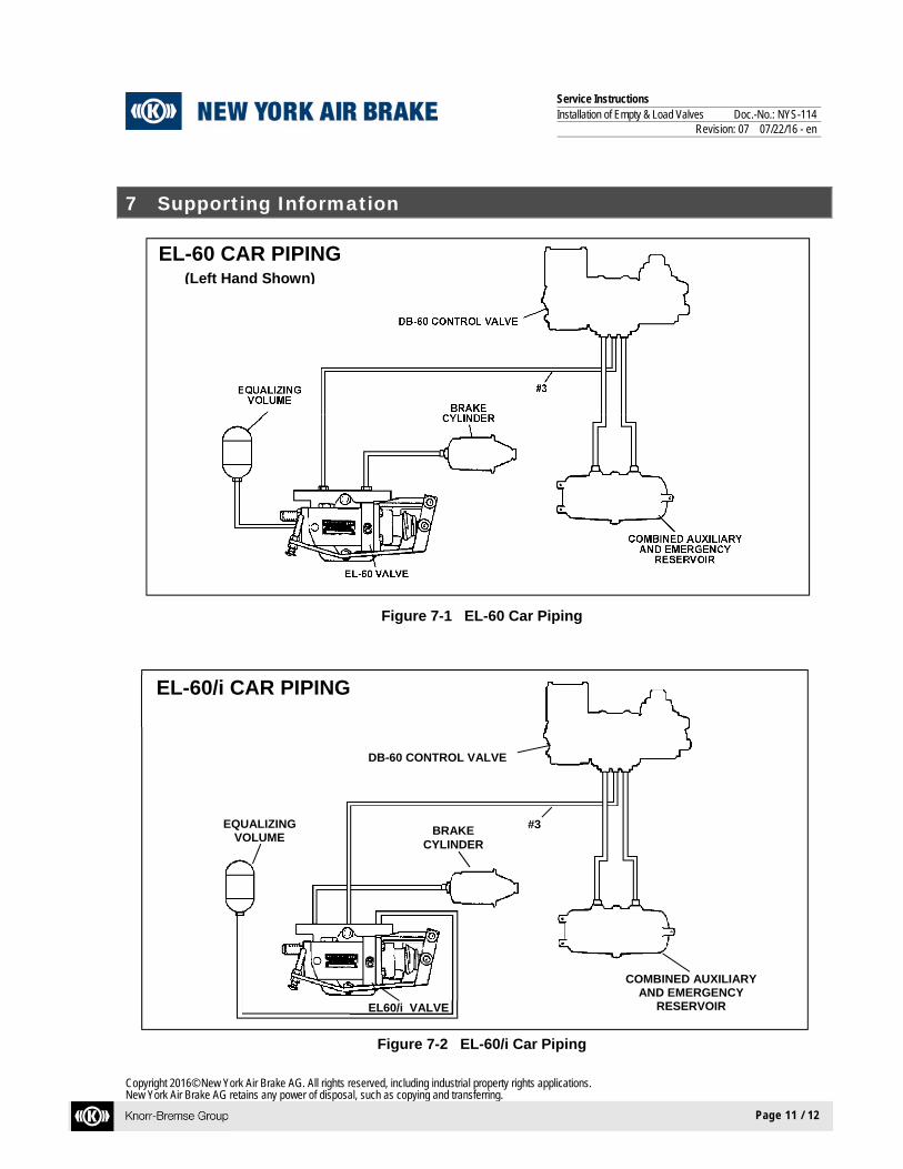
777665 - EL-60/i Valve Installation Drawing (see Figure 7-2 for Car Piping Diagram)
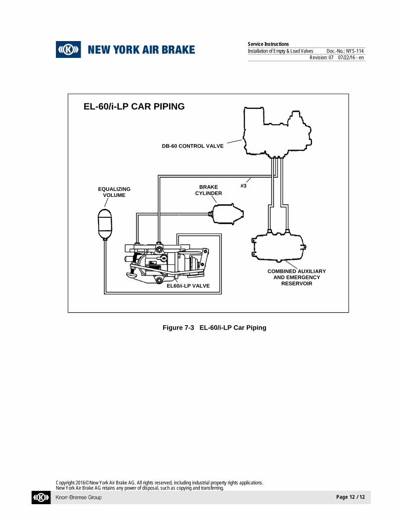
784452 - EL-60/i-LP Valve Installation Drawing (see Figure 7-3 for Car Piping Diagram)
EL-60 is available in right and left hand versions. Left hand models have the equalizing volume connec-tion on the left hand side of the pipe bracket when viewed from the front (the side with the nameplate). EL-60/i and EL-60/i-LP are available in right hand version only and have the equalizing volume connection on the back right hand side of the pipe bracket.
In a foundation or truck mounted brake where one empty load is required per control valve, the equalizing volume will be 250 cubic inches for 60%, 315 cubic inches for 50% and 375 cubic inches for 40%. In in-stances where two empty and load valves are required per control valve, the volumes would be propor-tionally smaller.
The visual indicator will be used to perform the following set-up function.

Service Instructions Installation of Empty & Load Valves Doc.-No.: NYS-114
Revision: 07 07/22/16 - en
Copyright 2016© New York Air Brake AG. All rights reserved, including industrial property rights applications. New York Air Brake AG retains any power of disposal, such as copying and transferring.
Page 10 / 12
6 Post-Installation Adjustment
NOTE The car must be empty and positioned on straight level track in order to properly set the EL-60 Empty Load valve.
1. With the brakes fully released loosen the lock nuts, which secure the sensor arm adjusting screw. Screw the adjusting screw in as far as it will go.
2. On new cars or on cars with new truck springs, pull the sensor valve arm down as far as it will go
and hold it in position. Screw the sensor valve adjusting screw out until it just touches the truck side frame; gently return the sensor valve to the release position. Turn the adjusting screw out the number of turns designated in Table 1 below minus four turns. Continue to step 4.
3. Pull the sensor arm down as far as it will go and hold it in position. Screw the adjusting screw out
until it just touches the truck side frame, gently return the sensor arm to the release position, and then screw the adjusting screw out the required complete turns for the valve in the following table in order to remove the slack from the sensor arm.
60% Valve 4 complete turns or (1/4" +/- 1/16") 50% Valve 6 complete turns or (3/8" +/- 1/16") 40% Valve 8 complete turns or (1/2" +/- 1/16")
Table 1
4. Lock the adjusting screw in place using one lock nut below and one lock nut above the sensor arm. Be careful not to change the setting of the adjusting screw while securing the lock nuts.
5. To Check the Setting With a freight single car test device connected to the car, charge BP to 90 psi and install a 1-1/2”
block under the sensor arm adjusting screw.
When the flowrator ball drops below the top of the tube, make a 20 to 30-psi brake pipe reduction and note that the Empty Load Indicator is not extended. Recharge BP and remove the block. When the flowrator ball drops below the top of the tube make another 20 to 30 psi brake pipe re-duction and note that the indicator is extended, indicating that the system is providing empty car braking. If the indicator is not extended repeat the set-up process.
If an Empty/Load stencil is applied to the car, it should reflect that no setup block is required or setup per NYAB service instruction NYS-114 is required.
Service Instructions Installation of Empty & Load Valves Doc.-No.: NYS-114
Revision: 07 07/22/16 - en
Copyright 2016© New York Air Brake AG. All rights reserved, including industrial property rights applications. New York Air Brake AG retains any power of disposal, such as copying and transferring.
Page 11 / 12
7 Supporting Information
Figure 7-1 EL-60 Car Piping
Figure 7-2 EL-60/i Car Piping
EL-60 CAR PIPING (Left Hand Shown)
EL-60/i CAR PIPING
EQUALIZING VOLUME
DB-60 CONTROL VALVE
BRAKE CYLINDER
COMBINED AUXILIARY AND EMERGENCY
RESERVOIR EL60/i VALVE
#3
Service Instructions Installation of Empty & Load Valves Doc.-No.: NYS-114
Revision: 07 07/22/16 - en
Copyright 2016© New York Air Brake AG. All rights reserved, including industrial property rights applications. New York Air Brake AG retains any power of disposal, such as copying and transferring.
Page 12 / 12
Figure 7-3 EL-60/i-LP Car Piping
EL-60/i-LP CAR PIPING
EQUALIZING VOLUME
DB-60 CONTROL VALVE
BRAKE CYLINDER
COMBINED AUXILIARY AND EMERGENCY
RESERVOIR EL60/i-LP VALVE
#3