nxe-iqm57a motherboard hardware document -...
TRANSCRIPT

Hardware Document nxtrdhw-001 R & D Team
NEXITE, Inc. 1 /17 Revision 1.0
NXE-IQM57A MotherBoard Hardware Document
March 24, 2011
Written by BC Yang
Revision 1.0

Hardware Document nxtrdhw-001 R & D Team
NEXITE, Inc. 2 /17 Revision 1.0
Document Revision History Released date Revision Description March 24, 2011 1.0
User’s Notice
No part of this product, including the schematics and BIOS may be reproduced, transmitted, transcribed, stored in a retrieval system, or translated into any language in any form by any means without the express written permission of NEXITE Inc. except the document kept by the purchaser for backup purposes.
© Copyright 2011 NEXITE Inc. All rights reserved

Hardware Document nxtrdhw-001 R & D Team
NEXITE, Inc. 3 /17 Revision 1.0
Contents of Table
I. Introduction
1. General Description ------------------------------------------------------------------ 4 2. Functional Block Diagram ------------------------------------------------------------ 7
II. System Overview
1. NXE-IQM57A Motherboard ------------------------------------------------------------ 8 2. Upgrade ability
2-1. Processor ------------------------------------------------------------------------------ 10 2-2. Memory ------------------------------------------------------------------------------ 10 2-3. BIOS ------------------------------------------------------------------------------------ 10
III. Jumpers , Connectors & Ports Descriptions
1. Board Switch Settings 1-1. RTC Clear Switch Description ----------------------------------------------------- 11 1-2. Internal HDMI / DVI Switch Description ----------------------------------------- 11
2. I/O Headers & Connector Descriptions 2-1. Motherboard Internal Connectors ----------------------------------------------- 12 2-2. Motherboard Rear Port Connectors ----------------------------------------------- 17
Hardware Document nxtrdhw-001 R & D Team
NEXITE, Inc. 4 /17 Revision 1.0
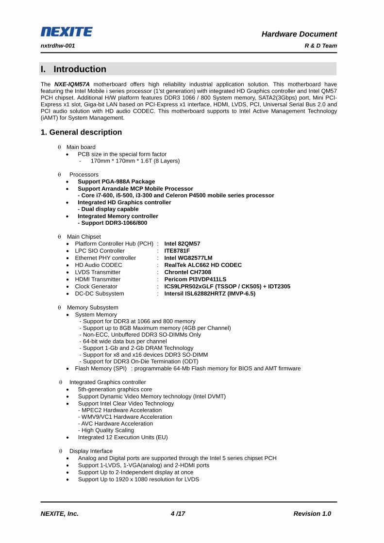
I. Introduction The NXE-IQM57A motherboard offers high reliability industrial application solution. This motherboard have featuring the Intel Mobile i series processor (1’st generation) with integrated HD Graphics controller and Intel QM57 PCH chipset. Additional H/W platform features DDR3 1066 / 800 System memory, SATA2(3Gbps) port, Mini PCI-Express x1 slot, Giga-bit LAN based on PCI-Express x1 interface, HDMI, LVDS, PCI, Universal Serial Bus 2.0 and PCI audio solution with HD audio CODEC. This motherboard supports to Intel Active Management Technology (iAMT) for System Management. 1. General description
θ Main board
• PCB size in the special form factor - 170mm * 170mm * 1.6T (8 Layers)
θ Processors
• Support PGA-988A Package • Support Arrandale MCP Mobile Processor
- Core i7-600, i5-500, i3-300 and Celeron P4500 mobile series processor • Integrated HD Graphics controller
- Dual display capable • Integrated Memory controller
- Support DDR3-1066/800 θ Main Chipset
• Platform Controller Hub (PCH) : Intel 82QM57 • LPC SIO Controller : ITE8781F • Ethernet PHY controller : Intel WG82577LM
• HD Audio CODEC : RealTek ALC662 HD CODEC • LVDS Transmitter : Chrontel CH7308 • HDMI Transmitter : Pericom PI3VDP411LS
• Clock Generator : ICS9LPR502xGLF (TSSOP / CK505) + IDT2305 • DC-DC Subsystem : Intersil ISL62882HRTZ (IMVP-6.5)
θ Memory Subsystem
• System Memory - Support for DDR3 at 1066 and 800 memory - Support up to 8GB Maximum memory (4GB per Channel) - Non-ECC, Unbuffered DDR3 SO-DIMMs Only - 64-bit wide data bus per channel - Support 1-Gb and 2-Gb DRAM Technology - Support for x8 and x16 devices DDR3 SO-DIMM - Support for DDR3 On-Die Termination (ODT) • Flash Memory (SPI) : programmable 64-Mb Flash memory for BIOS and AMT firmware
θ Integrated Graphics controller
• 5th-generation graphics core • Support Dynamic Video Memory technology (Intel DVMT) • Support Intel Clear Video Technology
- MPEC2 Hardware Acceleration - WMV9/VC1 Hardware Acceleration - AVC Hardware Acceleration - High Quality Scaling
• Integrated 12 Execution Units (EU)
θ Display Interface • Analog and Digital ports are supported through the Intel 5 series chipset PCH • Support 1-LVDS, 1-VGA(analog) and 2-HDMI ports • Support Up to 2-Independent display at once • Support Up to 1920 x 1080 resolution for LVDS

Hardware Document nxtrdhw-001 R & D Team
NEXITE, Inc. 5 /17 Revision 1.0
• Support Up to 1920 x 1200 @60Hz for HDMI (Not Tested) • Support Up to 2048 x 1536 @75Hz for VGA (Not Tested)
θ Intel Virtualization Technology (Intel VT)
• Support VT-d - Intel VT-d 1.0a spec.
• Support VT-x - Support by Processor core
θ Integrated Serial ATA Host Controller
• Support Up to 2 ports • Data transfer rates up to 3.0 Gb/s (SATA II) • Integrated AHCI controller • Support RAID mode for RAID 0/1 • Support SATA spec. Rev.1.0
θ USB Controllers
• Integrated Universal Host Controller Interface (UHCI) controller (USB 1.1) • Integrated Enhanced Host Controller Interface (EHCI) controller (USB 2.0) • Support Up to 8 ports (Rear-4ports, Internal-4ports) • Support legacy Keyboard / Mouse
θ Ethernet Subsystem
• Support 10/100/1000 Mbps • Supports IEEE802.3 • PCI Express based interface connection • Automatic MDI/MDIX crossover at all speeds of operation
θ Super I/O Subsystem
• Complies with LPC Interface spec. rev1.1 • Fan Speed controller
- Provide Smart Guardian Fan speed automatic control - CPU Fan and System Fan control - Monitor for CPU and system Fan speed
• Monitoring for CPU and system temperature • Support 4-standard serial port (Integrated 16C550 UART) • Support Watch Dog Timer
- Time resolution 1-minute or 1-second - Support up to 65535-minutes or 65535-seconds
θ Audio Subsystem
• RealTek ALC662 CODEC - High Definition Audio Codec
- All DAC support independent 44.1k/48k/96kHz sample rate - All ADC support independent 44.1k/48k/96kHz sample rate - Software selectable boost gain (+10/+20/+30dB) for analog microphone input
• Supports Line-out, Mic.-in and internal Line-out
θ PCI Interface Subsystem • Supports PCI Rev 2.3 spec at 33MHz • Support for 64-bit addressing on PCI using DAC protocol
θ PCI Express Subsystem
• Support mini-PCIe x1 slot • PCI Express 2.0 spec. running at 2.5GT/s • Support for full 2.5Gb/s bandwidth in each direction
θ Active Management Technology Subsystem (iAMT)
• Support advanced manageability feature - Client manageability using the wired network - Support KVM / Serial over Lan function

Hardware Document nxtrdhw-001 R & D Team
NEXITE, Inc. 6 /17 Revision 1.0
- Support IDE-R function
θ I/O Subsystem • Internal Interface connector
- Two SATA Connector (SATA-II, 3.0Gbps) - One 4P +12V DC-input Power Connector - Two 2*5-1 Header Connectors for four USB2.0 Interface - Three 2*5-1 Header for RS-232 Interface - One CPU FAN Connector (4P) with fan control
- One System FAN Connector (3P) - One 2*20 Header Connector for LVDS (Dual-channel support) - One 1*8 LCD Inverter Connector with brightness control - One 1*3 Header for Audio-out - One 2*9 Header Connector for HDMI/DVI - One 1*13 Header Connector for VGA - One 1*4 Header Connector for DC-output (for SATA Power) - One 2*5 Header for Power switch, HDD/PWR LED and Reset switch - One 2*5 Header for GPIO - One two-channel half-pitch DIP switch for RTC Reset
• External Interface connector (Rear-port) - Two HDMI ports - One D-SUB15 (RGB connector) - Four USB 2.0 ports - One 10/100/1000 Gbps Ethernet port - One Serial port (D-Sub 9p)-COM1 - One Line-out, One Mic-in - One +12V DC-input DIN-422 jack
θ Miscellaneous part
• Battery: Coin Type (CR2032) • One Power LED for system power ready indication (standby power LED)

Hardware Document nxtrdhw-001 R & D Team
NEXITE, Inc. 7 /17 Revision 1.0
2. Functional Block Diagram
Hardware Document nxtrdhw-001 R & D Team
NEXITE, Inc. 8 /17 Revision 1.0
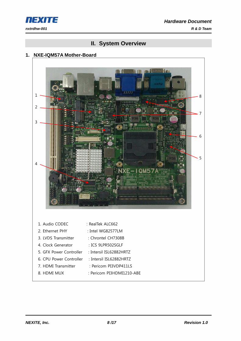
II. System Overview 1. NXE-IQM57A Mother-Board
1. Audio CODEC : RealTek ALC662
2. Ethernet PHY : Intel WG82577LM
3. LVDS Transmitter : Chrontel CH7308B
4. Clock Generator : ICS 9LPR502SGLF
5. GFX Power Controller : Intersil ISL62882HRTZ
6. CPU Power Controller : Intersil ISL62882HRTZ
7. HDMI Transmitter : Pericom PI3VDP411LS
8. HDMI MUX : Pericom PI3HDMI1210-ABE
1
2
3
4 5
6
8
7
Hardware Document nxtrdhw-001 R & D Team
NEXITE, Inc. 9 /17 Revision 1.0
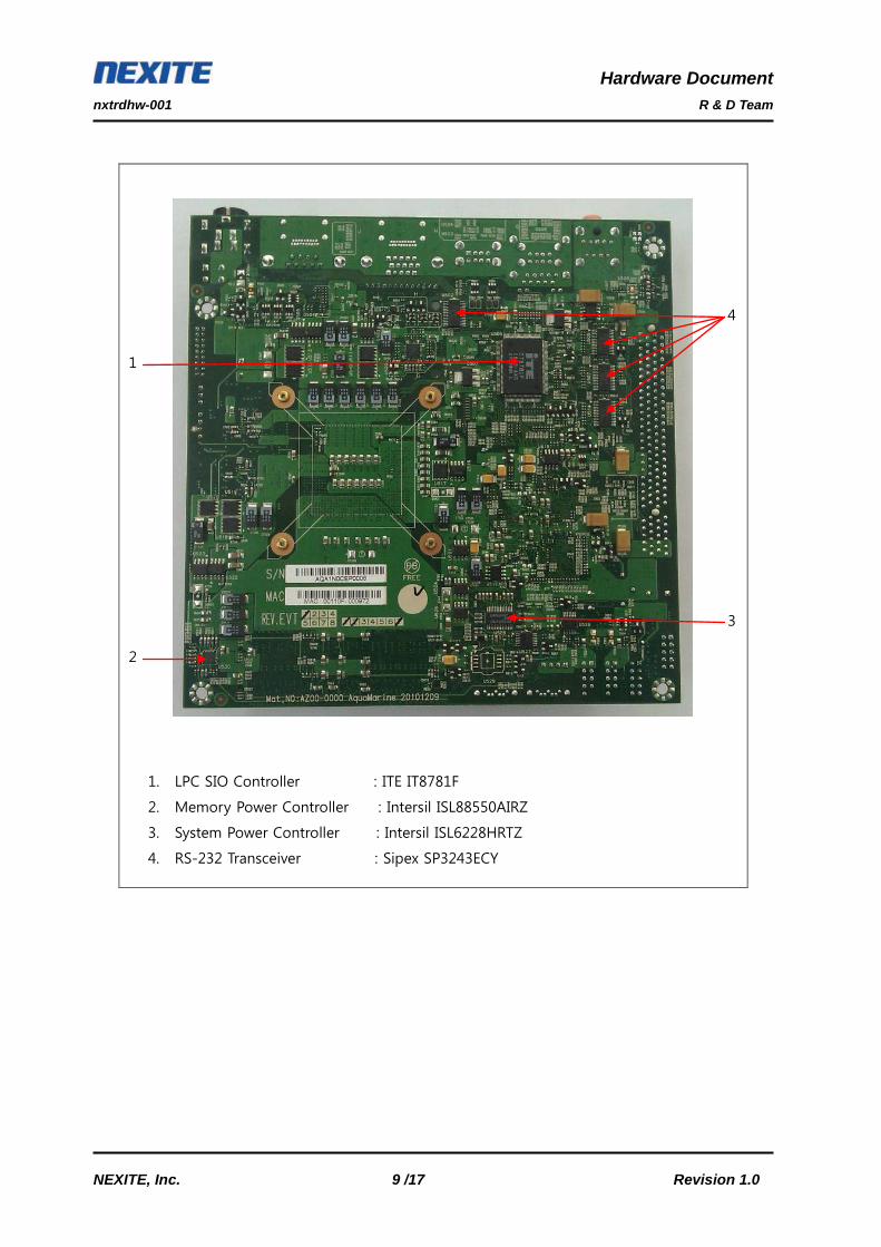
1. LPC SIO Controller : ITE IT8781F
2. Memory Power Controller : Intersil ISL88550AIRZ
3. System Power Controller : Intersil ISL6228HRTZ
4. RS-232 Transceiver : Sipex SP3243ECY
2
3
1
4
Hardware Document nxtrdhw-001 R & D Team
NEXITE, Inc. 10 /17 Revision 1.0
2. Upgradeability 2-1. Processor
• Available CPUs
- Mobile i series arrandale MCP proecssor - Core i7-600 series - Core i5-500 series - Core i3-300 series - Celeron P4500 processor - Support rPGA-988A package processor - Support Max 35W TDP
2-2. Memory
The NXE-IQM57A motherboard has two Small Outline Dual Inline Memory Module (SO-DIMM), minimum 512MB to maximum 8GB memory size. The BIOS detects the memory type, size, and speed through SMBUS interface between the core chipset and SO-DIMM module automatically. The motherboard supports the following memory features • Maximum memory size: 8GB • Support DDR3-1066, DDR3-800 • Two Memory Channel configurations: Dual-channel Symmetric or Dual-channel Asymmetric • 64-bit wide per channel • 1Gb and 2Gb memory technologies supported • Support for x8 and x16 unbuffered non-ECC DDR3 devices • Support for DDR3 On-Die Termination (ODT) • Supports partial writes to memory using data mask signals (DM) • Support Intel Flex Memory Technology mode
2-3 BIOS θ SPI Flash (64M-bit, 64Kbyte x 128blocks) The NXE-IQM57A motherboard uses a AMI BIOS which is stored in the flash memory. An old version of the BIOS can be updated to the newer version using the flash utility. And OEM logo and SETUP default values can be changed using the AMI utility. θ BIOS Specification • Includes the Video BIOS for integrated Graphic Controller • Supports PCI2.2, PnP1.0a, SMBIOS2.3, CDROM Boot 1.01, UUID, PXE boot, and so on • Supports S0,S1,S3,S4 and S5 state of ACPI Rev1.0b • Supports AMT 6.0
▶ For more details, refer to the BIOS documentation.
Hardware Document nxtrdhw-001 R & D Team
NEXITE, Inc. 11 /17 Revision 1.0
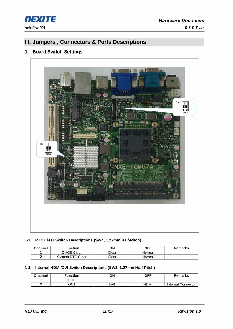
III. Jumpers , Connectors & Ports Descriptions 1. Board Switch Settings
1-1. RTC Clear Switch Descriptions (SW4, 1.27mm Half-Pitch)
1-2. Internal HDMI/DVI Switch Descriptions (SW3, 1.27mm Half-Pitch)
Channel Function ON OFF Remarks 1 CMOS Clear Clear Normal 2 System RTC Clear Clear Normal
Channel Function ON OFF Remarks 1 EQ0 - - 2 OC1 DVI HDMI Internal Connector
ON 1 2 SW4
ON
1 2 SW3

Hardware Document nxtrdhw-001 R & D Team
NEXITE, Inc. 12 /17 Revision 1.0
2. I/O Headers & Connectors Descriptions 2-1. Motherboard Internal Connectors
1
2
3
4
5
6
7
8
9
10
11
12

Hardware Document nxtrdhw-001 R & D Team
NEXITE, Inc. 13 /17 Revision 1.0
1) Front IO Connector (Front1, 2.54mm normal pin header)
2) Internal Audio Connector (CN11, 12505WS-03 / YeonHo)
3) Internal VGA Connector (CN6, 20010WS-13 / YeonHo)
Pin number Signal description 1 HDD LED + 2 SYSTEM LED + 3 HDD LED - 4 SYSTEM LED - 5 GND 6 GND 7 Power Button Switch 8 System Reset switch 9 GND 10 GND
Pin number Signal description 1 Line-Out Right 2 Ground 3 Line-Out Left
Pin number Signal description 1 RED 2 GND 3 BLUE 4 GND 5 GREEN 6 GND 7 DDC DATA 8 GND 9 HSYNC 10 VSYNC 11 GND 12 DDC CLK 13 VCC (+5V)
1 3
13 1
1 2 3 4 5 6 7 8 9 10

Hardware Document nxtrdhw-001 R & D Team
NEXITE, Inc. 14 /17 Revision 1.0
4) Internal HDMI/DVI Connector (CN18, YDW200-18 / YeonHo)
5) System Fan Connector (SYS1, HF0803E / FOXCONN)
6) CPU Fan Connector (CPU_FAN1, 1470947-1 / AMP)
7) SATA Power Connector (CN20, SMW250-04 / YeonHo)
Pin number Signal description 1 GND 2 CLK- 3 CLK+ 4 GND 5 DATA2- 6 DATA2+ 7 GND 8 DATA1+ 9 DATA1-
10 GND 11 DATA0- 12 DATA0+ 13 GND 14 DDC DATA 15 DDC CLK 16 GND 17 Hot Plug Detect 18 VCC(+5)
Pin number Signal description 1 GND 2 +12V 3 Fan Tachometer
Pin number Signal description 1 GND 2 +12V 3 Fan Tachometer 4 Fan Control
Pin number Signal description 1 +12V 2 GND 3 GND 4 +5V
1
2
17
18
1 2 3 4
1 2 3
4 1

Hardware Document nxtrdhw-001 R & D Team
NEXITE, Inc. 15 /17 Revision 1.0
8) LVDS I/F Connector (CN17, DF13A-40DP-1.25V / Hirose)
9) LVDS Inverter Connector (CN16, 12505WS-08A00 / YeonHo)
Pin number Signal description Pin number Signal description 1 TX0- 21 TX7+ 2 TX0+ 22 TX_CLK2- 3 TX1- 23 TX_CLK2+ 4 TX1+ 24 GND 5 TX2- 25 PULL-UP(+5V) 6 TX2+ 26 PULL-DOWN(GND) 7 GND 27 GND 8 TX_CLK1- 28 GND 9 TX_CLK1+ 29 GND 10 TX3- 30 +5V 11 TX3+ 31 +5V 12 TX4- 32 +5V 13 TX4+ 33 +3.3V 14 GND 34 +3.3V 15 TX5- 35 +12V 16 TX5+ 36 +12V 17 GND 37 +12V 18 TX6- 38 +12V 19 TX6+ 39 +12V 20 TX7- 40 +12V
Pin number Signal description 1 +12V 2 +12V 3 +12V 4 BACK-LIGHT ENABLE 5 BRIGHTNESS ADJ 6 GND 7 GND 8 GND
8
1

Hardware Document nxtrdhw-001 R & D Team
NEXITE, Inc. 16 /17 Revision 1.0
10) GPIO I/F Connector (CN19, 2.54mm Normal Pin Header)
11) System Power Input Connector (CN10, ABA-POW-003-K04 / Lotes)
12) DC-In Jack (CN9, Power DIN-422)
Pin number Signal description 1 +5V 2 GPIO5(default:GPI) 3 GPIO1(default:GPO) 4 GPIO6(default:GPI) 5 GPIO2(default:GPO) 6 GPIO7(default:GPI) 7 GPIO3(default:GPO) 8 GPIO8(default:GPI) 9 GPIO4(default:GPO)
10 GND
Pin number Signal description 1 GND 2 GND 3 +12V_IN 4 +12V_IN
Pin number Signal description 1 GND 2 +12V_IN 3 GND 4 +12V_IN
1 2 3 4 5 6 7 8 9 10
1 2
3 4

Hardware Document nxtrdhw-001 R & D Team
NEXITE, Inc. 17 /17 Revision 1.0
2-2. Motherboard Rear-port Connectors
No. Functions Location Note (1) +12V DC-In Jack (Power DIN422) CN9 (2) COM1 Serial port CN8 (3) VGA output port (analog) CN5 (4) HDMI output port CN4, CN7 (5) USB 2.0 port CN3, CN2 (6) 10/100/1000 Gbps Ethernet port CN2 (7) Audio port
- Lime : Line-out - Pink : Mic-in
CN1
(2) (3)
(1) (4)
(5)
(6)
(7)