numerical modelling of heat transfer in a channel … · numerical modelling of heat transfer in a...
TRANSCRIPT

International Journal of Engineering Research and Development
e-ISSN: 2278-067X, p-ISSN: 2278-800X, www.ijerd.com
Volume 8, Issue 12 (October 2013), PP. 06-18
6
Numerical modelling of heat transfer in a
channel with transverse baffles
M.A. Louhibi1, N. Salhi
1, H. Bouali
1, S. Louhibi
2
1Laboratoire de Mécanique et Energétique, Faculté des Sciences, BP. 717 Boulevard Mohamed VI -
60000 Oujda, Maroc. 2Ecole National des sciences Appliquées, Boulevard Mohamed VI - 60000 Oujda, Maroc.
Abstract:- In this work, forced convection heat t ransfer inside a channel o f
rectangular sec tion, containing some rectangular baffle p lates , is numerica lly
analyzed. We have developed a numer ica l model based on a fini te -volume method ,
and we have so lved the coupling pressure -veloci ty by the SIMPLE a lgori thm [6] . We
show the e ffects o f var ious parameters o f the baff les, such as, baf f le ’s he ight ,
loca tion and number on the i sotherms, s tream l ines, tempera tures distr ibutions and
loca l Nusse lt number va lues. I t i s concluded tha t: I ) The baff les loca tion and he ight
has a meaningful e ffec t on i sotherms, streamlines and to ta l hea t t ransfer through the
channel . ( I I ) The heat t ransfer enhances wi t h increas ing bo th baff le ’s height and
number.
Keywords:- Forced convect ion, Baff les, Finite volume method, Simple, Quick, k-
I. INTRODUCTION In recent years, a large number o f exper imental and numerical works were
per formed on turbulent forced convect i on in heat exchangers wi th di fferent type of
baff les [1 -4] . This interes t i s due to the var ious industr ial appl icat ions of this type
of configurat ion such as cooling of nuclear power plants and aircraf t engine . . . e tc .
S. . V Patankar and EM Sparrow [1] ha ve appl ied a numer ica l solution procedure in
order to treat the problem of f luid flo w and heat t ransfer in ful ly developed heat
exchangers. These one was equipped by iso thermal plate p laced transversely to the
direc t ion of flo w. They found tha t the f low f i e ld i s character ized by s trong
recircula t ion zones caused by so lid pla tes. They concluded that the Nussel t number
depends strongly on the Reynolds number, and i t i s higher in the case o f ful ly
developed then tha t o f laminar flo w regime.
Demar tini et a l [ 2] conducted numer ica l and experimenta l stud ies o f turbulent
f low ins ide a rec tangular channel conta ining two rectangular baff les. The numerical
result s were in good agreement wi th those obta ined by experiment. They no ted that
the baff les p lay an impor tant role in the dynamic exchangers studied. Indeed,
regions o f high pressure 'rec irculat ion regions ' a re formed near ly to chicanes .
Recent ly, Nasiruddin and Sidd iqui [3] s tudied numerical ly e ffects of baff les on
forced convection f low in a heat exchanger . The effects o f s ize and incl ina tion angle
of baff les were de ta i led . They considered three di fferent arrangements o f baffles .
They found that increas ing the s ize o f the ver t ical baffle substantial ly improves the
Nusse lt number . Ho wever , the pressure loss i s a l so impor tant . For the case o f
incl ined baff les, they found tha t the Nusselt number is maximum for angles of
incl ina tion d irected do wnstream of the baff le , with a minimum of pressure loss.
More recent ly, Sa im e t al [4] presented a numerical study of t he dynamic behavior
of turbulent air flo w in hor izonta l channel with transverse baff les. They adapted
numerical f ini te volume method based on the SIMPLE a lgori thm and chose

Numerical modell ing of heat transfer in a channel with…
7
model fo r treatment o f turbulence. Resul t s obtained for a case o f such type, a t
low Reynolds number, were presented in te rms of ve loci ty and temperature f ields.
They found the exis tence of rela t ively strong recircula t ion zones near the baffles .
The eddy zones a re responsib le o f local var iat ions in the Nusse lt s numbers along the
baff les and wal ls .
We kno w that the pr imary heat exchanger goal is to e ff ic ient ly transfer heat
from one f luid to ano ther separa ted, in most pract ical cases, by so lid wal l . To
increase heat t ransfer , severa l approaches have been proposed. We can c i te the
spec i fic treatment o f so lid separa t ion sur face ( roughness, tube winding, vibrat ion,
etc . ) . This transfer can also be improved by creation of longi tudina l vort ices in the
channel . These eddies are produced by introducing one or more transverse barr ier s
(baffle plates) ins ide the channel . The formation of these vort ices downstream of
baff les causes recirculat ion zones capable o f rap id and eff icient heat t ransfer
between sol id wal ls a nd f luid f low. I t i s this approach that we wi l l fol lo w in this
study. Indeed, we are interested in this work on the numerical model ing of dynamic
and thermal behavior o f turbulent forced convection in hor izontal channel where two
wal ls are raised to a high temperature. This channel may contain one or severa l
rectangular baff les.
A spec ia l inte rest i s given to the influence of di fferent parameters, such as height ,
number and baffle posit ions on heat t ransfer and f luid f lo w.
II. MATHEMATICAL FORMULATION The geometry of the p roblem is shown schematica l ly in Figure 1 . I t i s a
rectangular duc t wi th isothermal hor izonta l wal ls , crossed by a sta t ionary turbulen t
f low. The physica l propert ies are considered to be constants.
Figure 1: The studied channel
At each point o f the f low the ve loc ity has components (u, v) in the x and y
direc t ions, and the temperature i s denoted T . The turbulence model ing i s handled by
the c lass ical model (k - ) . k is the turbulent kinet ic energy and the viscous
diss ipat ion of turbul ence.
The Transpor t equat ions (continuity, momentum, temperature, turbulent
kinet ic energy and d iss ipat ion of turbulence) governing the sys tem, are wr it ten in
the fo l lo wing genera l fo rm :
)1()()(
S
y
y
x
x
y
v
x
u
Where ρ is the densi ty of the fluid passing
through the channel and ɸ, F φ and Sφ are given by:
Equat ions S
Cont inui té 1 0 0
Quant i té de
mouvement selon x
u t
x
P

Numerical modell ing of heat transfer in a channel with…
8
Quant i té de
mouvement selon y
v t
y
P
Energie to tale T
T
t
0
Energie cinét ique
turbulente
k
k
t
G .
Dissipa tion turbulente
t
kC
GC
)
(
2
1
With :
222
22y
u
x
v
y
v
x
uG t µ and µ t represent , respec tively,
the dynamic and turbulent viscosit ies.
2
.k
Ct
The constants used in the turbule nce model (k -Ɛ) Are those adopted by
Chieng and Launder (1980) [8] :
C 1C 2C T k
0 ,09 1,44 1,92 0,9 1 1 ,3
Boundary condit ions :
At the channel inle t :
inUu ; 0v and inTT
2/32 1,0005,0 kandUk in
At sol id wal ls :
0 vu ; 0k inw TTTand
At the channel exit s:
The gradient o f any quanti ty, wi th respec t to the longitud ina l direc t ion x is
nul .
Our goal is to determine veloc ity and temperature f ields, as well as the
turbulence parameters. Par t icular a t tent ion i s given to the quant i ficat ion parameters
ref lect ing hea t exc hanges such as the Nussel t number ( local and average) .
III. NUMERICAL FORMULATION The computer code that we have developed i s based on the fini te volume
method. Computat ional domain i s d ivided into a number o f s t i tches. To choose the
number of cel l s used in t his s tudy, we per formed several simula tions on a channel
(wi th or wi thout baffles) . F inal ly, we have op ted for a 210 × 90 meshes .
The mesh d imensions are var iab les; they t ighten a t the sol id walls
ne ighborhoods. Consequently, the s t i tch density i s higher near the hot wal ls and
baff les.
We consider a mesh having dimensions ∆x and ∆y. In the middle o f each
volume we consider the points P , ca l led centers o f control vo lumes. E , W, N, S are
Numerical modell ing of heat transfer in a channel with…
9
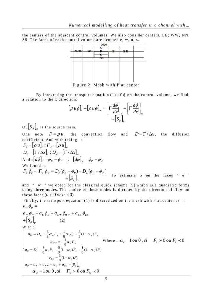
the centers o f the adjacent contro l vo lumes. We also consider centers, EE; WW, NN,
SS. The faces o f each cont rol vo lume are denoted e, w, n, s .
Figure 2: Mesh with P at center
By integrat ing the transport equation (1) o f ɸ on the contro l volume , we find,
a relat ion to the x direct ion:
P
we
we
S
dx
d
dx
duu
Où P
S is the source term.
One no te uF , the convect ion f low and xD / , the di ffus ion
coefficient . And wi th taking :
wwee uFuF ;
wwee xDxD /;/
And : WPwPEe dd ;
We found :
P
WPwPEewwee
S
DDFF
)()( To est imate ɸ on the faces " e "
and " w " we opted for the c lassical quick scheme [5] which i s a quadrat ic forms
using three nodes. The choice o f these nodes i s dictated by the direc t ion of f low on
these faces )00( uoru .
Fina lly, the transpor t equation (1) i s d iscre t ized on the mesh wi th P at center as :
)2(P
EEEEWWWWEEWW
PP
S
aaaa
a
With :
PEEEWWWP
eeEE
wweeeeeE
wwWW
wweewwwW
Saaaaa
Fa
FFFDa
Fa
FFFDa
)1(8
1
)1(8
1)1(
8
6
8
38
1
)1(8
3
8
1
8
6
Where : 00,01 eee FouFsiou
00,01 www FouFsiou

Numerical modell ing of heat transfer in a channel with…
10
The same thing i s done for the ver t ical "y" direct ion, using the faces "n" and
"s" and by introducing the Quick diagram nodes N, NN, S and SS.
i f convection flo w and di ffusion coefficient o f the sides "e" , "w" , "s" , "n" are
kno wn And espec ia l ly the source term P
S , the solution of equation (2) t hen gives
us the va lues of ɸ in di fferent P nodes .
One notes that to acce lerate the convergence of equation (2) we have introduced a
relaxat ion fac tor :
)3(1 0
PPP
EEEEWWWWEEWWP
P
aS
aaaaa
Where 0
P is the va lue of P in the
previous step .
The source term appears especia l ly in the conservat ion of momentum
equat ions in the fo rm of a pressure gradient which i s in pr inc iple unkno wn . To get
around this coupling we have chosen to use in our code the "Simple" algori thm
developed by Pantankar [7] . The bas ic idea of this algor i thm is to assume a f ie ld o f
ini t ia l pressure and inject i t in to the equat ions o f conserva tion of momentum. Then
we solve the sys tem to f ind a f ield o f intermediate speed (which i s not fa ir because
the pressure isn t . ) The continuity equat ion i s t ransformed into a pressure correct ion
equat ion. This las t i s de termined to find a pressure correc tion that wi l l injec t a
new pressure in the equations o f motion. The cycle i s repeated as many t imes as
necessary unti l a pressure correct ion equal "zero" corresponding to the a lgori thm
convergence. In the end we solve the transport equations o f T , k and Ɛ.
In this approach, a problem is encountered . I t is known as the checkerboard
problem.
The r i sk i s that a pressure field can be highly d isturbed by the sensed
formula tion which comprises per forming a l inear interpolat ion for es t imate the
pressure value on the facets o f the cont rol volume. To circumvent this problem we
use the so -ca lled s taggered gr ids proposed by Har low and Welch [6] . In thi s
technique, a f ir st gr id p ressure (and other scalar quanti t ies T , k and Ɛ ) is p laced in
the center o f the con trol vo lume. While o ther staggered gr ids are adopted for the
ve loc ity components u and v ( see Figure 3) .
Figure 3: Shi fted mesh
The sca lar var iables, including pressure, are stored a t the nodes (I , J ) . Each
node (I , J ) i s sur rounded by nodes E, W, S and N. The horizonta l velocity component
u i s sto red on faces "e" and "w", whi le the ver t ica l component v is stored on the
faces denoted "n" and "s" .
So the control vo lume for pressure and o ther scalar quant i t ies T , k and Ɛ is
),();1,();1,1();,1( jijijiji

Numerical modell ing of heat transfer in a channel with…
11
For component u cont rol vo lume is
),1();1,1();1,();,( jIjIjIjI .
Whi le for the v component we use : )1,1();,();,1();1,1( JiJiJiJi .
By integra t ing the conservat ion momentum equation in the horizontal direc t ion on
the volume ),1();1,1();1,();,( jIjIjIjI , we found :
)(),(),1(
)4(
1
,,
jjnbnb
JiJi
yyJIPJIPua
ua
Where :
NNNNNNSSSSSS
EEEEEEWWWWWWnbnb
uauauaua
uauauauaua
The coefficients anb are
determined by the quick scheme ment ioned above.
Simi lar ly, the integrat ion of conservat ion mo mentum equat ion in the ver t ical
direc t ion on the volume
)1,1();,();,1();1,1( JiJiJiJi , gives us :
)(),()1,(
)5(
1
,,
iinbnb
jIjI
xxJIPJIPva
va
One considers pr imar i ly an ini t ia l pressure field P*. The provisional so lution
of the equat ions (4) and (5) wi l l be denoted u* and v
*. We note that u
* and v
* doesn’t
checks the continuity equati on, and:
)6()(),(),1( 1
**
*
,*
,
ayyJIPJIP
ua
ua
jj
nbnb
JiJi
)6()(),()1,( 1
**
*
,*
,
bxxJIPJIP
va
va
ii
nbnb
jIjI
At this stage any one of the three var iables i s correct . They require correction :
)7(
'
'
'
*
*
*
vvv
uuu
PPp
Injec t ing (7) in equations (4) , (5) and (6) we find :
)8()(),('),1('
'
'
1
,,
ayyJIPJIP
ua
ua
jj
nbnb
JiJi
)8()(),(')1,('
'
'
1
,,
bxxJIPJIP
va
va
ii
nbnb
jIjI
Numerical modell ing of heat transfer in a channel with…
12
At this leve l , an approximation i s in troduced. In order to l inear ize the
equat ions (8) , the terms nbnbua ' and nbnbva ' are s imply neglected .
Normally these terms must cancel a t the procedure convergence . That i s to
say that this omission does not a ffec t the f ina l result . Ho wever , the convergence
rate is changed by this simpl i ficat ion. I t turns out that the correct ion P ' i s
overest imated by the Simple algor i thm and the ca lculat ion tends to diverge. The
remedy to s tab il ize the calculat ions i s to use a re laxa tion fac tor .
We Note that a fur ther trea tment of these te rms i s proposed in the so -cal led
algori thms "SIMPLER" and "SIMPLEC" [7] .
The equations (8) become:
)9(),('),1('' , aJIPJIPdu JiJi
)9(),(')1,('' , bJIPJIPdv jIjI
Avec :
Ji
jj
Jia
yyd
1et
Ij
ii
jIa
xxd
1
With :
Ji
jj
Jia
yyd
1 and
Ij
ii
jIa
xxd
1
Equat ions (9) give the correc tions to app ly on veloc it ies through the formulas
(7) . We have therefore :
)10(),('),1('
,*
,
aJIPJIPd
uu
Ji
JiJi
)10(),(')1,('
,*
,
bJIPJIPd
vv
jI
jIjI
Now the discret ized contin ui ty equat ion on the control vo lume of scalar quanti t ies i s
wr i t ten as fol lows :
0)()(
)()(
,1,
,,1
jIjI
JiJi
vAvA
uAuA
Where an are the s ize o f the corresponding faces .
The introduction of the veloc ity correct ion equations (10) in the continui ty
equat ion gives a fina l equat ion al lowing us to de termine the scope of pressure
correc tions P:
)11()1,('')1,(''
),1(''
),1(''),(''
11
1
1
JIPaJIPa
JIPa
JIPaJIPa
JIJI
JI
JIJI
The a lgori thm can be summarized as fo l lows : one sta r t s fro m an ini t ial
f ield**** ,, andvuP , wi th represents the sca lar quan ti t ies T, k and Ɛ. Then the
sys tem (6) is so lved to have new values o f ** vandu .
Then the sys tem (11) i s solved for the correc tions f ield pressure P '.
Thereaf ter , pressure and veloc ity are corrected by equat ions (7) and (10) to have P ,
u and v.

Numerical modell ing of heat transfer in a channel with…
13
We solve the fo l lo wing transport equation of sca lar quanti t ies (2) , ɸ = T, K
and Ɛ .
Finally, we consider :
**** ;;; vvuuPP .
And the cyc le i s repeated unti l convergence.
IV. RESULTS AND DISCUSSIONS The dimensions o f the channel presented in this work are based on
experimental data published by Demart ini et a l [2] . The air flo w is carr ied out under
the fo l lo wing condi t ions .
Channel length: 𝐿 = 0 .554 m ;
Channel diameter D = 0.146 𝑚 ;
baffle he ight : 0 <ℎ <0 1. 𝑚 ;
baff le thickness: δ = 0 .01 𝑚 ;
Reynolds number : 𝑅𝑒 = 8 .73 104
;
The hydrodynamic and thermal boundary condit ions are given by :
At the channel inle t :
inuu =7,8m/s;
0v ; inTT =300 K
On the channel walls:
0 vu and KTT w 373
At the channel exit the sys tem is assumed to be ful ly developed, ie :
0
x
Tx
vx
u
Fir s t , we compared the s truc ture o f streamlines and i so therms in a channel
wi thout baff le wi th those ob ta ined when we int roduce baffle having a height h =
0.05 m (Case 2 -1) a t the absc ise 𝐿 1 = 0 .218 𝑚 . Indeed, in figures 4 and 5 we present
streamlines and i so therms for two configurat ions.
These result s c lear ly show the impor tance of p resence of baff le (act ing as a
cooling f in) . Indeed the baff le increases heat t ransfer between the wal l an d the
f luid . This increase is caused by rec irculat ion zones do wnstream of the baff le .
(a)
(b)
Figure 4: s t reamlines: (a ) case 1 ; (b) case 2 -1
(a)
(b)
Figure 5: Iso therms: (a) case 1 ; (b) case 2 -1

Numerical modell ing of heat transfer in a channel with…
14
We then s tudied the inf luence of baff le he ight on flo w s tructure and hea t
t ransfer . We chose the heights (h = 0 .05 m; cases 2 -1) h = 0 , 073 𝑚 (Case 2 -2) and h
= 0, 1 𝑚 (case 2 -3) .
The figures 6 and 7 present streamlines and i sotherms for a channel containing baff le
wi th di fferent he ights .
(a)
(b)
Figure 6: streamlines : (a ) case 2 -2 ; (b) case 2 -3
(a)
(b)
Figure 7: Iso therms: (a) case 2 -2; (b) case 2 -3
I t is c lear that the i sotherms are more condensed near baff le , as and when the
he ight h increases. This ind icates an increase o f heat t ransfer near baffle . Indeed, the
increase in h expanded exchange area be tween f luid and walls . In add it ion, when h
increases , the recircula t ion zone beco mes increas ingly impor tant ( see Figures 4 (b)
and figures 6 (a) and (b)) . This causes an acce lerat ion of f low, which improves hea t
t ransfer wi thin the channel .
We present figures 8 and 9 in order to iden t i fy the influence of h on
ve loc it ies and temperature p rofi les a long y at x = 0 .45 from channel inlet . Four
va lues o f h are considered.
Figure 8: Hor izontal velocity Profi les along y at x = 0.45 « inf luence of h »
Figure 9: Temperature p rof i les along y at x = 0.45 m « inf luence of h »

Numerical modell ing of heat transfer in a channel with…
15
These resul ts al low us to conclude that the increase o f baffle he ight has two
contrad ic tory effects. I t is t rue tha t there i s substant ial increase in heat exchange
(appearance of recircula t ion zones most co mmon), but the re is a lso a loss o f pressure
( f low b lockage) .
In the purpose of measur ing the influence of 'h ' on loca l heat t ransfer , we
have presented in figure 10, the local Nusse lt number a long the channel for the four
cases o f h considered. I t sho ws tha t upstream of the baff le (x <0.2 m) curves are
confused , whi le , just af ter baffle locat ion, effec t o f baff le he ight on Nussel t
number beco me increas ingly impor tant away from the baffles .
0
50
100
150
0 0.2 0.4 0.6
Nu Cas 21
Nu Cas 22
Figure 10 : Local number Nu along the channel « inf luence of h »
We then s tudied the inf luence of baff les number and posi t ion 'F igure 11 and 12 '.
(a)
(b)
(c)
Figure 11 : S treamlines : (a) cas 3 -1; (b) cas 3 -2; (c) cas 3 -3
We consider two baffles of same height h = 0.08 m. The fir s t baff le i s pl aced
at the distance 𝐿1 = 0 .15 𝑚 , whi le the second is posi t ioned at the d istance d 1 = 0 .05
m from the f irs t (case 3 -1) , d 1 = 0 .10 m (case 3 -2) and d 1 = 0 .15 m (case 3 -3) . We
note the existence of two rec irculat ion zones downstream of the f ir st baff le . Also the
f irs t recircula t ion zone 'defined by baffles ' becomes increas ingly important , which
contr ibute to an increase in heat t ransfer in this area, as sho wn in Figure 12. Indeed,
when the baff les are c lose to each o ther 'd 1 small ' , the fluid i s blocked in the
chimney del imi ted by x = L 1 and x = L1 + d 1 . This reduces the f low speed at tha t
Numerical modell ing of heat transfer in a channel with…
16
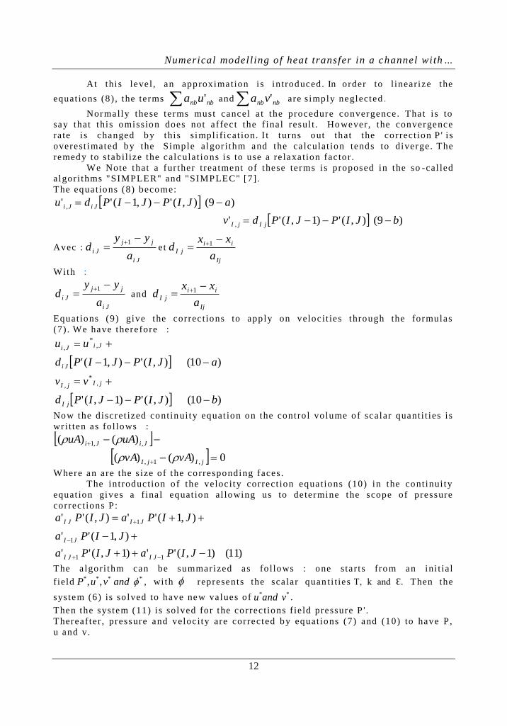
loca tion and thus there wi l l be a decrease in the heat t ransfer in this a rea. Or when
d 1 increases, the f luid has suff ic ient space to move rap idly, hence hea t t ransfer
increases in this zone 'see figure15 ' .
(a)
(b)
(c)
Figure 12 : Iso therms
(a) : « cas 3 -1 » ; (b) : « cas 3 -2 » ; (c) « cas 3 -3 »
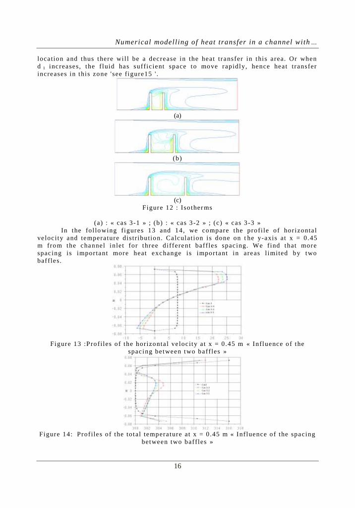
In the fol lo wing figures 13 and 14, we compare the profi le o f hor izonta l
ve loc ity and tempera ture dis tr ibution. Calculat ion i s done on t he y-axis at x = 0 .45
m from the channel inlet for three di fferent baff les spac ing. We find that more
spac ing i s impor tant more heat exchange i s impor tant in areas l imi ted by two
baff les.
Figure 13 :Prof i les o f the horizonta l ve loc ity a t x = 0.45 m « Influence of the
spac ing be tween two baff les »
Figure 14: Prof i les o f the total tempera ture at x = 0.45 m « Inf luence of the spacing
between two baffles »

Numerical modell ing of heat transfer in a channel with…
17
Figure 15 present the loca l Nusse lt number along the channel fo r three
considered spacing d 1 = 0 .05m, 0 .1m and 0 .15m.
Figure 15 :Local Nusse l t number along the channel « Influence of baff les number
and posit ion »
We dist ingue two areas :
The fir s t def ined by 0 <x <0.3m whi le the second by x> 0.3m. For the fir st
region, an increase in nu mber of baffles improves the hea t t ransfer ; whereas the
reverse is t rue for the second zone.
We chooses to show the inf luence of baff les number on hea t t ransfer along
the channel for three cases : Channel wi thout baff les, channel containing a s ingle
baff le and channel conta ining two baffles 'Figure 16 '.
I t should be noted tha t genera l ly, hea t t ransfer i s proport iona l to baff les
number. Indeed, the Nussel t number character izing hea t t ransfer wi thin the channel
increases wi th increasing baffles number.
Figure 16: Local Nusse lt number a long the channel
V. CONCLUSION The thermal behavior o f a stat ionary turbulent forced convection f low wi thin
a baff led channel was ana lyzed . The result s show the ab il i ty o f our code to predict
dynamic and thermal f ields in var iou s geometr ic si tuat ions. We stud ied mainly the
inf luence of baff les he ight and spac ing on heat t ransfer and f luid f low. One can
conclude tha t:
1 - Increase in the baffle he ight improves heat t ransfer between channel wall s
and fluid passing through i t ;
2 - Heat t ransfer becomes increasingly impor tant wi th adding baffles .
3 - The spacing d 1 be tween baff les has di fferent e ffec ts on loca l heat
t ransfer . Any t ime d 1 has no t a lo t of inf luence on the overal l hea t t ransfer in the
channel .
In perspec tive , we inten d deepen and c lar i fy our result s . Indeed, we wi l l adapt our
code to others geometr ic cases (non -rec tangular baffles or baffles inc lined) . Fina lly,
we wi l l a l so try to re fine more the turbulence model .

Numerical modell ing of heat transfer in a channel with…
18
REFERENCES [1] . S.V.PATANKAR, E.M.SPARROW, « Ful ly develope d f low and heat t ransfer
in ducts having stream wise -per iodic var ia t ions of cross -sect ional a rea »,
Journa l o f Heat Transfer , Vol . 99, p (180 -6) , 1977.
[2] . L.C.DEMARTNI, H.A.VIELMO and S.V.MOLLER, « Numerica l and
experimental analys is o f the turbulent flo w thr ough a channel wi th baff le
plates », J . o f the Braz. Soc. o f Mech. Sci . & Eng. , Vol. XXVI, No. 2 , p (153 -
159) , 2004.
[3] . R.SAIM, S.ABBOUDI, B.BENYOUCEF, A.AZZI, « Simula tion numér ique de
la convect ion forcée turbulente dans les échangeurs de chaleur à fa isceau et
calandre munis des chicanes transversales », Algér ian journa l o f app lied f luid
mechanics / vol 2 / 2007 (ISSN 1718 – 5130) .
[4] . M. H. NASIRUDDIN, K. SEDDIQUI « Heat transfer t augmenta tion in a heat
exchanger tube using a baff le», Interna tional journa l o f H eat and Fluid Flo w,
28 (2007) , 318 -328.
[5] . H.K. Vers teeg ; W. Malalasekera « An introduction to computa tional f luid
dynamics » ISBN 0.582 -21884-5.
[6] . F. Harlo w; J . Welsh ; « Staggered gr id », Numerical calcula t ion of t ime
dependent viscous incompress ible flo w wi th free sur face. Physics o f f luids,
vol . 8 ; pp 2182 -2189; 1965.
[7] . Patankar , S.V. (1980) , «Numer ica l Heat Transfer and Fluid Flow»,
[8] . Chieng C.C. and Launder B.E. «On the calcula t ion of turbulent heat t ransport
downstream fro m an abrupt p ipe expansion», Numeri cal Heat Transfer , vol . 3 ,
pp. 189-207 .