numerical modelling and geotechnical monitoring of an
TRANSCRIPT
1
Numerical Modelling and Geotechnical Monitoring of
an Anchor Wall System for a Deep Excavation in
Lima ConglomerateGerman D. Matos Paucar, MSc1, Jose W. Gutierrez Lazares, MSc2
1Universidad Nacional de Ingenieria, Peru, [email protected], 2 Universidad Nacional de Ingenieria, Peru, [email protected]
The city of Lima is located in an area where the soil is mainly
composed of coarse granular material known as Lima conglomerate.
It is characterized by having good geomechanical properties from a
civil engineering point of view. However, there has always been some
difficulty in obtaining the necessary parameters, basically because of
the lack of laboratory equipment.
On the other hand, the city has played a key role in the country's
economic growth over the last two decades, where many new and
modern buildings have taken place which in turn include the
construction of several basements as part of them. In this regard, the
Anchor Wall system (Sort of a combination of Diaphragm wall and
Soil Nailing) has shown a good performance during the excavation
phase, taking advantage of the quite good geotechnical
characteristics of this alluvial gravel deposit.
This research aims at determining the soil parameter in an
indirect way, it means that the real lateral displacements, obtained
by geotechnical monitoring in a given project, will be compared with
that output data obtained by a previous numerical simulation. It is
worth mentioning that the first input data used in the computational
stage was based on a proper collection of information about the
predominant soil in Lima.
The results show coherence between the horizontal
displacements seen in-situ with that obtained by The Finite Element
Method (FEM); thus contributing to the geomechanical
characterization of Lima Conglomerate. Last but not least, the safety
and efficiency of this technology were proven once again during the
project monitoring.
Keywords— Anchor Wall System, Lima Conglomerate, Finite
Element Method, Inclinometer, Coarse granular soils.
I. INTRODUCTION
It has been many years since a large number of building
structures started constructing in the Peruvian capital, most
them imply the building of several basements for parking
spaces, so it is no wonder that many excavations took place in
the city, moreover when it comes to the urban area.
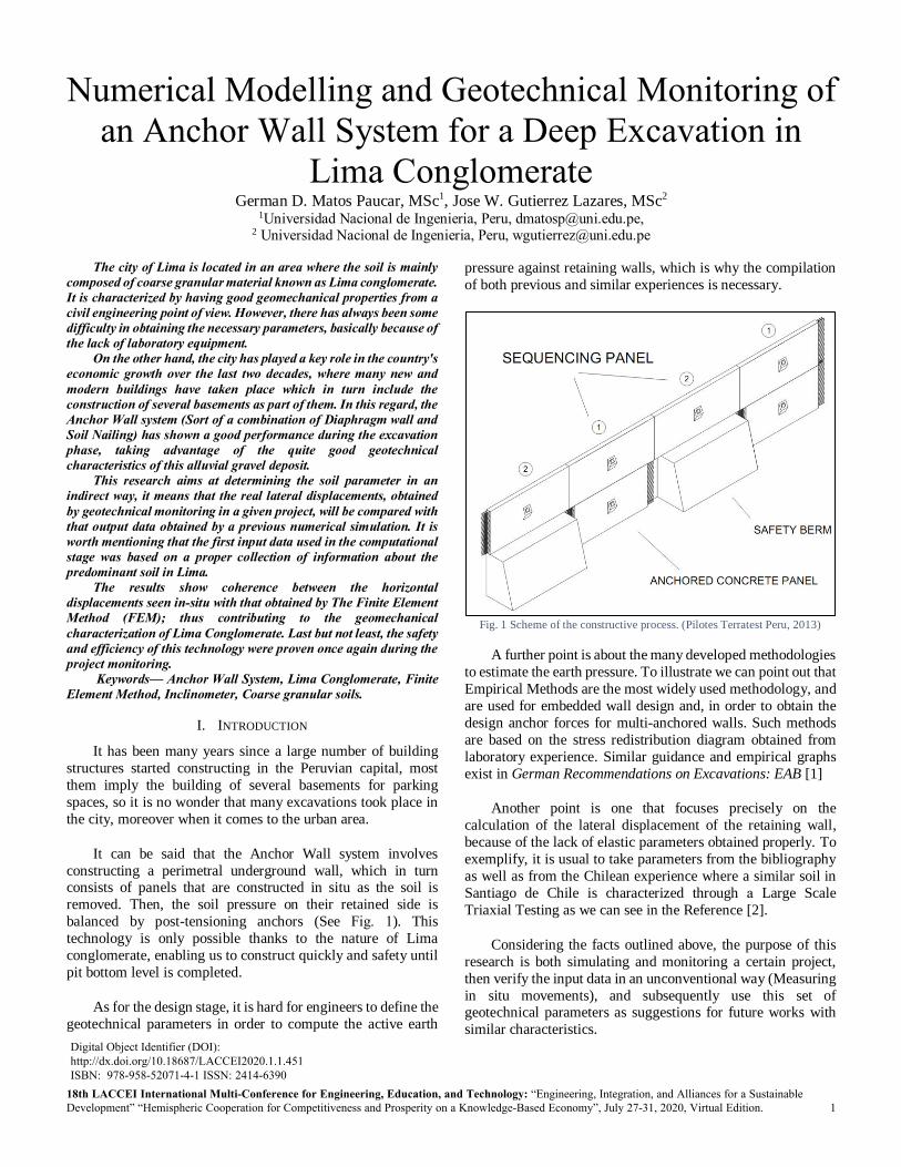
It can be said that the Anchor Wall system involves
constructing a perimetral underground wall, which in turn consists of panels that are constructed in situ as the soil is
removed. Then, the soil pressure on their retained side is
balanced by post-tensioning anchors (See Fig. 1). This
technology is only possible thanks to the nature of Lima
conglomerate, enabling us to construct quickly and safety until
pit bottom level is completed.
As for the design stage, it is hard for engineers to define the
geotechnical parameters in order to compute the active earth
pressure against retaining walls, which is why the compilation
of both previous and similar experiences is necessary.
Fig. 1 Scheme of the constructive process. (Pilotes Terratest Peru, 2013)
A further point is about the many developed methodologies
to estimate the earth pressure. To illustrate we can point out that
Empirical Methods are the most widely used methodology, and
are used for embedded wall design and, in order to obtain the
design anchor forces for multi-anchored walls. Such methods
are based on the stress redistribution diagram obtained from
laboratory experience. Similar guidance and empirical graphs
exist in German Recommendations on Excavations: EAB [1]
Another point is one that focuses precisely on the
calculation of the lateral displacement of the retaining wall,
because of the lack of elastic parameters obtained properly. To
exemplify, it is usual to take parameters from the bibliography
as well as from the Chilean experience where a similar soil in
Santiago de Chile is characterized through a Large Scale
Triaxial Testing as we can see in the Reference [2].
Considering the facts outlined above, the purpose of this
research is both simulating and monitoring a certain project,
then verify the input data in an unconventional way (Measuring
in situ movements), and subsequently use this set of geotechnical parameters as suggestions for future works with
similar characteristics. Digital Object Identifier (DOI): http://dx.doi.org/10.18687/LACCEI2020.1.1.451 ISBN: 978-958-52071-4-1 ISSN: 2414-6390
18th LACCEI International Multi-Conference for Engineering, Education, and Technology: “Engineering, Integration, and Alliances for a Sustainable Development” “Hemispheric Cooperation for Competitiveness and Prosperity on a Knowledge-Based Economy”, July 27-31, 2020, Virtual Edition.

18th LACCEI International Multi-Conference for Engineering, Education, and Technology: “Engineering, Integration, and Alliances for a Sustainable
Development” “Hemispheric Cooperation for Competitiveness and Prosperity on a Knowledge-Based Economy”, 29-31 July 2020, Buenos Aires, Argentina. 2
II. GEOTECHNICAL CHARACTERIZATION OF LIMA
CONGLOMERATE
The great characteristics of the typical soil in Lima cannot
be better illustrated as in the Fig. 2, where the height of the
almost vertical excavation is around 6 meters without any type of retaining structure which lead us to expect high parameters
in comparison with other typical granular soils. So, let us recall
some former studies.
Fig. 2 View of the typical Gravel in Lima. Height of excavation is
approximately 6 meters (Pilotes Terratest Peru, 2012)
According to the reference [3], most of Lima area is covered by alluvial gravels that are found at few meter depth.
The same authors found Shear wave velocities (V𝑠) of the order
of 800 𝑚 𝑠⁄ (See Fig. 3) Which corresponds to a Very dense
soil and Soft Rock for the International Building Code [4].
Fig. 3 Shear-wave velocity profiles of Lima conglomerate
Similarly, the reference [5] summarized results (Shear
Strength Parameters) from many In-situ Direct Shear Test
carried out for different projects in Lima over the time,
concluding that the ranges of values for Cohesion (C) and Friction Angle (ϕ) are the following 20-40KPa and 40-55°,
respectively. Obviously, such values can vary as the depth
increases.
Fig. 4 Scheme of an In-Situ Direct Shear Test
III. PROJECT OVERVIEW
The foundation pit is located in San Isidro district, which is
located in the south of the city center of Lima, Peru. The
building was designed intending to be a Multi-family
residential. In addition, it is included the construction of five
basements (Around 16.00 meters) and that is why the Anchor
Wall system was meant to retain the soil during the excavation
stage (See Fig. 5).
Fig. 5 The project during excavation stage
A. Geotechnical Investigations
The subsurface conditions and soil properties at the site
were obtained from the geotechnical investigation and
laboratory tests, summarized in the TABLE I. The site generally
featured Poorly Graded Gravel (GP). Note that strength
parameters were based on the experience gained over the last
years, but not for any test performed.

18th LACCEI International Multi-Conference for Engineering, Education, and Technology: “Engineering, Integration, and Alliances for a Sustainable
Development” “Hemispheric Cooperation for Competitiveness and Prosperity on a Knowledge-Based Economy”, 29-31 July 2020, Buenos Aires, Argentina. 3
TABLE I
FOUNDATION SOIL LAYERS
Depth Soil
(USCS)
Unit
Weight
Friction
Angle Cohesion
From To (KN m3⁄ ) (°) (KN m2⁄ )
0.00 1.20 Pt 19 20 5
1.20 4.00 GP 21 38 20
4.00 8.00 GP 22 40 30
8.00 20.00 GP-GM 22 42 40
B. Characteristics of the Wall Anchored System
Moving on to the specific part which will be the subject of
this research, let us take the equivalent of three panels located
on one of the axis (See Fig. 6). those wall panels will be
stabilized by applying of post-tensing anchors on their external
surface. Likewise, The TABLE II details the dimensions of
every element that form the anchors.
Fig. 6 Front view of the area stabilized by post-tensing anchors.
TABLE II
TECHNICAL SPECIFICATIONS OF THE ANCHORS
Level Depth Quantity eh LB LF Load
(m) (m) (m) (KN)
1 -2.5 3 5.0 3.5 7.5 480
2 -6.0 3 5.0 3.5 6.3 550
3 -9.5 3 5.0 3.5 5.5 550
4 -13.0 2 5.3 3.5 5.5 580
Where:
eh : Horizontal spacing
LB : Bond Length
LF : Free Length
IV. GEOTECHNICAL MODELISATION
This stage design aims to define the mechanical
characterization as well as the geometric model of the different
materials that form the whole body, trying to reflect what
happens in the reality at the maximum possible. All those data
will be part of the input data for a subsequent numerical
simulation by using ABAQUS code in order to estimate the
change of stresses and strains state taking place in the earth
structure under different construction stages. Nevertheless, we
have to emphasize that good results will depend on both correct
choice of parameters and a correct definition of boundary
conditions.
A. Constitutive Models
As we know, soils are not linearly elastic and perfectly
plastic for the entire range of loading, rather soils are complex
materials, showing non-linear, anisotropic and time-dependent
behavior when are subjected to stress. Conversely, reinforced
concrete features an almost defined behavior, besides, the range
of deformations are expected to be in the elastic regime. The
TABLE III provides information on each Constitutive Model
for each material and type of analysis.
TABLE III
SUMMARY OF CONSTITUTIVE MODELS USED IN THIS WORK
Constitutive
Model Material
Application
Case
Dependent
Parameters
Linear
Elasticity
Rock and
Concrete Initial Stress
𝑫(𝐸, 𝑣)
Perfect
plasticity Concrete Slope Stability 𝑫(𝐸, 𝑣, 𝜎𝑦)
Mohr-Coulomb Soil Slope Stability 𝑫(𝐸, 𝑣, Ψ, ∅, ∁)
Where:
𝐸 : Young modulus
𝑣 : Poisson Modulus
𝜎𝑦 Yield strength
Ψ : Angle of Dilatancy
B. Material Properties
For practical reasons, we considered just one soil layer in the whole body analyzed. Otherwise, a greater number of
variables would become necessary. And then again its soil
parameters assumed were mainly grounded on the following:
The geotechnical investigations mentioned before
Previous studies in the city and detailed in the
reference [3], and [5].
Comparable experiences as that described in the
reference [2].
In the cases where coarse material, the dilatancy angle
has been deduced from a simple relationship
recommended by the reference [6]: Ψ = ∅′ − 30
The TABLE IV and TABLE V show the mechanical
properties for the soil and the concrete, respectively. TABLE IV
SOIL PROPERTIES USED IN ABAQUS CODE
Material 𝜸𝑑𝑟𝑦
(𝐾𝑁 𝑚3⁄ )
∅′ (°)
𝑪 (𝐾𝑃𝑎)
𝑬 (𝑀𝑃𝑎)
𝒗 (−)
𝚿 (°)
Gravel 20 40 30 300 0.25 30
TABLE V
CONCRETE PROPERTIES USED IN ABAQUS CODE
Material Width (𝑚)
𝜸 (𝐾𝑁 𝑚3⁄ )
𝝈𝒚
(𝑀𝑃𝑎)
𝑬 (𝐺𝑃𝑎)
𝒗 (−)
Concrete 0.30 24 28 20 0.18

18th LACCEI International Multi-Conference for Engineering, Education, and Technology: “Engineering, Integration, and Alliances for a Sustainable
Development” “Hemispheric Cooperation for Competitiveness and Prosperity on a Knowledge-Based Economy”, 29-31 July 2020, Buenos Aires, Argentina. 4
C. Geometry
A series of different geometries were performed, being the
most stable that one which considered 18438 three-dimensional
solid elements (types-hexahedra). As might be supposed, the
elements are finer near to the area of our interest (The side of the wall). The Fig. 7 describes the whole body, including forces
acting on itself.
Furthermore, vertical displacement at the lateral surface
boundaries is defined as null. Likewise, both vertical and
horizontal displacements at the bottom of the geometry are
supposed to be impeded.
Lateral surface: 𝑈𝑥 = 0, 𝑈𝑦 = 0 and 𝑈𝑧 ≠ 0
Bottom surface: 𝑈𝑥 = 0, 𝑈𝑦 = 0 and 𝑈𝑧 = 0
It is noticeable that the soil mass is subjected to a volume
force (gravity force) as well as a surface load on the bottom part
equivalent to 10 𝐾𝑁 𝑚2⁄ (Dead load) as is suggested in
German Recommendations on Excavations: EAB [1]
Fig. 7 Final geometric Representation of the model
D. Construction Process The present methodology consists in simulating
sequentially each layer is removed during the excavation.
Therefore, this strategy of simulation allows the model to
imitate the real sequence of construction of this structure. The
Fig. 8 describes the sequential decrement of each layer, from
where we can note the following:
The height chosen for every decrement is 3.5 meters and
those are represented in odd numbers.
The even numbers represent the application of loads
(Nodal forces) on the wall, simulating the anchors that take
place immediately after the excavation.
Fig. 8 Sequential order of the construction process set up in ABAQUS
E. Analysis of the Output Data
The Fig. 9 illustrates the results (Deformed mesh) of the
model under all considerations mentioned above. Additionally,
it is important to recall that the diaphragm will move as a rigid
body and will force the walls to move together, which bring us
to the next step: Take a cross section to build up a displacement
curve: Depth vs Lateral Displacement (See Fig. 10), where the
most striking point to note is that the maximum lateral
displacement is 7mm, located in the central part of the wall.
Fig. 9 Deformed mesh of total displacements. Scale x100

18th LACCEI International Multi-Conference for Engineering, Education, and Technology: “Engineering, Integration, and Alliances for a Sustainable
Development” “Hemispheric Cooperation for Competitiveness and Prosperity on a Knowledge-Based Economy”, 29-31 July 2020, Buenos Aires, Argentina. 5
Fig. 10 Lateral Displacements developed on the excavated side
V. GEOTECHNICAL INSTRUMENTATION FOR MONITORING
FIELD PERFORMANCE: INCLINOMETERS
Previous to any work in the project, two inclinometer pipe
(Labeled as “B01” and “B02”) were installed, exactly behind
the analyzed panel walls, with a view to monitoring the lateral
displacements while the soil removal is performed. It is worth
mentioning that these elements have an embedded part in the
soil below dredge line, the length of which is named
penetration.
The period for the measurements depended on the works
of the foundation pit. Therefore, each measure was carried out
immediately upon an important step was done, such as:
Excavation, Building of the wall, Application of loads, or even
an extraordinary event happens.
Fig. 11 Field measurements during excavation stage.
Final curves of lateral displacement of the diaphragm wall
for measuring point “B01” and “B02” at depth of 20 m are
shown in Fig. 12 and Fig. 13. The lateral displacement of the
diaphragm wall overall decrease with the increasing of
excavation depth. Both graphs display a maximum
displacement of 6.1 mm which occurs on the top of the wall.
Let us compute the shear deformation, defined as 𝛿ℎ =ℎ 𝐻⁄ , where “h” is the maximum horizontal displacement and
“H” the height of the excavation. Hence: 𝛿ℎ = 0.39 1000⁄ ,
which is below the maximum allowed according to the
reference [7], where the value of 1 1000⁄ is the maximum limit
for this type of structures.
Fig. 12 Lateral displacement profile measured in situ. Point B01

18th LACCEI International Multi-Conference for Engineering, Education, and Technology: “Engineering, Integration, and Alliances for a Sustainable
Development” “Hemispheric Cooperation for Competitiveness and Prosperity on a Knowledge-Based Economy”, 29-31 July 2020, Buenos Aires, Argentina. 6
Fig. 13 Lateral displacement profile measured in situ. Point B02
VI. CONCLUSIONS
As it can be see, the shear deformation (𝛿ℎ) is smaller than the maximum allowed, which is also related to a correct
execution of the constructive process. It was verified during all
the period of monitoring; thus reducing potential foundation
settlement in the adjacent buildings. In few words, the
performance of this technology has been proven quantitatively.
This research also demonstrates that, the design of this
retaining structure, by using either Equilibrium Limit Analysis
or Empirical Methods, has been oversized, basically because
the smaller parameters considered. In other words, the greater
the calculated forces are, the higher sizes of the every element
will be.
The similarity between both Lateral displacements graphs,
it means those curves obtained by numerical simulation and by
In-situ measurement, bears out the shear strength parameters
that we used as the input data: ∅ = 40°; ∁= 30KPa.
Finally, the elastic parameters used for the gravel that were
taken from both the literature review and the results of the
gravel of Santiago de Chile (By using Large-scale Triaxial
Testing) are consist with those measured on site. Therefore, the
following values are suggested for future projects that will take
place in Lima metropolitan area: E = 300MPa; v = 0.25.
VII. ACKNOWLEDGMENTS
Research Institute of the Civil Engineering Faculty at the
Universidad Nacional de Ingenieria (IIFIC) as well as the
company Pilotes Terratest Peru for the financial support and
sharing their work experience.
VIII. REFERENCES
[1] German Society for Geotechnics, Recomendations on Excavations
(EAB), 2nd ed., Berlin: Ernst & Sohn, 2008.
[2] R. Verdugo y K. Hoz, «Caracterización Geomecánica de Suelos
Granulares Gruesos,» Revista Internacional de Desastres Naturales,
Accidentes e infrestructura Civil, 2006.
[3] D. Calderon, T. Sekiguchi, Z. Aguilar, F. Lazares and S. Nakai,
“Dynamic characteristics of the surface soils in Lima, Perú,” in 8th
International Conference in Urban Earthquake Engineering., Tokyo,
2011.
[4] T. L. Patterson, Illustrated 2009 Building Code Handbook, McGraw-
Hill, 2010.
[5] S. Sánchez Rodríguez, J. M. Rodríguez Ortiz, J. D. López Valero, . C.
Laina Gómez and Á. Jiménez Morales, “Caracterización de Suelos
Granulares Gruesos. El caso de la Grava de Lima,” Reconocimiento,
tratamiento y mejora del terreno: 10º Simposio Nacional de Ingeniería
Geotécnica, pp. 305-312, 19, 20 y 21 Octubre 2016.
[6] S. Helwany, Applied soil mechanics with ABAQUS applications, John
Wiley & Sons, 2007.
[7] P. J. Sabatini, D. G. Pass y R. C. Bachus, GEOTECHNICAL
ENGINEERING CIRCULAR NO. 4: Ground Anchors and Anchored
Systems (FHWA-IF-99-015), Washington: Federal Highway
Administration, 1999, p. 281.
[8] ABAQUS, “6.14 Documentation,” Dassault Systemes Simulia
Corporation, vol. 651, 2014.
[9] CISMID, "Estudio de Vulnerabilidad y Riesgo Sísmico en 42 distritos de
Lima y Callao," Lima, 2004.
[10] M. Calvello and R. Finno, "Selecting Parameters to Optimize In Model
Calibration by Inverse Analysis," Computers and Geotechnics, pp. 410-
424, 2004.
[11] K. Terzaghi, “Erdbaumechanik auf bodenphysikalischer grundlage,”
1925.
[12] E. Santoyo Villa y J. Segovia Pacheco, «Muros Milan,» de Manual de
construcción geotécnica, parte I, Sociedad mexicana de mecánica de
suelos, 2002, pp. 57-203.
[13] L. F. Raygada Rojas, "Análisis de la Estabilidad y Deformaciones en el
Acantilado de la Costa Verde," UNIVERSIDAD NACIONAL DE
INGENIERIA, Lima, 2011.
[14] D. M. Potts and L. Zdravkovic, Finite Element Analysis In Geotechnical
Engineering: Application, vol. 2, T. Telford, Ed., 2001.
[15] A. Martinez, "Conglomerado de Lima Metropolitana en Cimentaciones,"
in Conferencia Internacional de Ingeniería Sísmica, Lima, 2007.
[16] K. H. De la Hoz Alvarez, «Estimación de los parámetros de resistencia
al corte en suelos granulares gruesos,» Universidad de Chile, Santiago
de Chile, 2007.
[17] M. Braja, Principles of Foundation Engineering, Sacramento: California
State University, 1999.
[18] J. E. Alva Hurtado, Diseño de Cimentaciones, 1ra Edicion ed., Lima:
Fondo Editorial ICG, 2011.
[19] Sociedad Mexicana de Mecanica de Suelos, Manual de Construcción
Geotécnica Tomo I, Ciudad de Mexico: Noriega Editores, 2007.