numerical modeling of rudder sheet cavitation including...
TRANSCRIPT

CAV03-GS-12-005 Fifth International Symposium on Cavitation (CAV2003)Osaka, Japan, November 1-4, 2003
Numerical modeling of rudder sheet cavitation includingpropeller/rudder interaction and the effects of a tunnel
Hanseong LeeOcean Engineering Group
The University of Texas at Austin, [email protected]
Spyros A. KinnasOcean Engineering Group
The University of Texas at Austin, [email protected]
Hua GuOcean Engineering Group
The University of Texas at Austin, [email protected]
Shreenaath NatarajanOcean Engineering Group
The University of Texas at Austin, [email protected]
ABSTRACT
This paper presents the coupling of a vortex latticemethod (MPUF-3A), a finite volume method (GBFLOW-3D), and a boundary element method (PROPCAV) to allowfor the prediction of rudder sheet cavitation, including theeffect of propeller, as well as the effects of tunnel walls.
The unsteady cavity prediction on the propellerblades is performed using MPUF-3A to satisfy both a con-stant pressure condition on the cavity surface and the flowtangency condition on the cavity and blade surfaces. Theeffects of the tunnel and a vortical inflow are modeled viaGBFLOW-3D by solving the 3-D Euler equations with slipboundary conditions on the walls and by representing theeffect of the propeller blades via body forces.
The cavity prediction on the rudder is accomplishedvia PROPCAV (which can handle back and face leadingedge or mid-chord cavitation) in the presence of the 3-Dflow field produced by the propeller. This flow-field isdetermined via GBFLOW-3D, in which the propeller isrepresented via a non-axisymmetric distribution of bodyforces. The effects of the tunnel walls are also consideredin this case by applying a boundary element method on thewalls, in the presence of the rudder.
A multi-block Euler scheme is also developed in or-der to determine the effect of the rudder on the propellerinflow.
The present method is first validated by performingconvergence studies on a cavitating rudder with varyingnumber of panels. Then, the predicted cavity shapes ona (horn-type) rudder downstream of a propeller are com-pared to those observed in a experiment performed in acavitation tunnel.
INTRODUCTION
Rudders operate in the stern of a ship behind the pro-peller slipstream, and are subjected to an accelerated andswirled inflow induced by the hull and the propeller. Theswirled flow induced by the propeller increases the angleof attack to some parts of the rudder, and as a result theloading of the rudder increases, and sheet cavitation oftenappears over the rudder surface. Therefore, the interactionbetween the propeller and the rudder is very important forthe analysis of both devices.
There have been a lot of numerical methods, based onpotential theory, which predict the cavitating performanceof a propeller or a hydrofoil (rudder). Two methods, i.e.,a vortex lattice method (VLM) and a boundary elementmethod (BEM), have been successfully applied to the sheetcavity prediction.
Previous work
A vortex lattice method was first applied to the analy-sis of unsteady fully wetted performance of a marine pro-peller subject to non-uniform inflows by [Kerwin and Lee1978]. Later, their method was extended to analyze 3-Dunsteady sheet cavitation using the linearized cavity theoryby [Lee 1979, 1981; Breslin et al. 1982]. However, the lin-ear theory predicts longer cavity extent as the blade thick-ness increases, which is contrary to the non-linear theory[Uhlman 1987] as well as the short cavity theory [Tulinand Hsu 1980]. [Kerwin et al. 1986] modified the methodof [Lee 1979, 1981; Breslin et al. 1982] to take into ac-count the non-linear blade thickness effect by implement-ing the leading edge correction [Kinnas 1985, 1991]. [Kin-nas and Fine 1989] extended the method to predict un-steady partial cavity with prescribed mid-chord and/or face

CAV03-GS-12-005 Fifth International Symposium on Cavitation (CAV2003)Osaka, Japan, November 1-4, 2003
cavity detachment, and [Kudo and Kinnas 1995] extendedthe method to treat super-cavitating propellers subject tosteady flow. Recently, the method was named MPUF-3Aby including the ability to search for mid-chord cavitation[Kinnas et al. 1998a, 1999]. The latest version of MPUF-3A [Lee et al. 2003] includes the effect of hub, non-linearthickness-loading coupling, and wake alignment in uni-form and inclined inflow.
The boundary element method has been widely usedfor the prediction of sheet cavitation due to the defect ofthe linear theory in the vortex lattice method. A non-linear potential based boundary element method was firstapplied for the analysis of a cavitating propeller subjectto non-axisymmetric inflows by [Fine 1992; Kinnas andFine 1992; Fine and Kinnas 1993b], and for the analy-sis of the cavitating hydrofoils by [Kinnas and Fine 1993;Fine and Kinnas 1993a]. Their method, named PROP-CAV, discretizes the exact blade surface and places con-stant strength of dipole and source distributions on thediscretized panels. Thus, this method predicts more ac-curately the pressures and cavity patterns at the propellerleading edge, trailing edge and tip where the linear cavitytheory breakdowns in the vortex lattice method. PROP-CAV was extended to predict the face and/or back cavi-tation with searched cavity detachment by [Kinnas et al.1997; Mueller and Kinnas 1997; Mueller 1998; Muellerand Kinnas 1999], and to treat the mixed partial and super-cavity on both face and/or back sides of the blade simulta-neously by [Young and Kinnas 1999, 2001]. PROPCAVwas further extended to treat super-cavitating propellerswith finite thickness trailing edge as well as surface pierc-ing propellers by [Young 2002; Young and Kinnas 2002,2003]. The treatment of a developed tip vortex cavity anda procedure for the fully unsteady wake alignment werealso incorporated in PROPCAV by [Lee and Kinnas 2001;Lee 2002; Lee and Kinnas 2003]. [Kinnas et al. 1998b,2000] applied a boundary element method to analyze thecavitating flow over 3-D hydrofoil subject to a uniform in-flow inside a circular tunnel, and the interaction betweenhydrofoil and tunnel wall was determined in an iterativemanner.
The accurate prediction of the effective wake is verycrucial in determining the propeller loading and the flowfield induced by the propeller over the rudder downstream.[Choi and Kinnas 1998; Kinnas et al. 2000; Choi and Kin-nas 2001] applied a finite volume method to predict the3-D effective wake of single propeller in unbounded or in-side of a circular section tunnel. A three-dimensional un-steady Euler solver based on a finite volume approach andthe pressure correction method, was developed to predictthe unsteady effective wake for propellers subject to non-axisymmetric inflows by [Choi and Kinnas 2000a,b; Choi2000; Choi and Kinnas 2003]. Recently, [Kinnas et al.2003; Natarajan 2003] extended the 3-D Euler solver to in-
clude the effect of a non-axisymmetric strut and pod, andto evaluate the flow field over the rudder induced by thepropeller.
The hydrodynamic interaction between propeller andrudder is of great importance because of its effect on theperformance of both. [Tamashima et al. 1993] used asimplified propeller theory, which treats the propeller asan actuator disc, to calculate the performance of the pro-pellers, and a panel method to calculate the forces actingon the rudder. In [Han et al. 1999], they developed a nu-merical technique using boundary element method to ana-lyze the propeller-rudder interaction, and the calculated re-sults were compared with the measured from experiments.[Shen et al. 1997] performed a series of experiments tostudy the effect of ship hull and propeller on the rud-der cavitation, and compared the measured pressure dis-tribution over the rudder with those predicted by a panelmethod. [Han et al. 2001] used a surface panel methodto solve the flow around a horn-type rudder and a vortex-lattice method to solve the flow around the propeller, re-spectively. The three-dimensional flow around the rudderand the propeller was computed simultaneously, consid-ering the interactions between the two. In [Achkinadzeet al. 2003], a velocity based boundary element method hasbeen applied to predict the rudder forces subject to the non-axisymmetric inflow to the rudder induced by propeller.
Present work
In the present work, a vortex lattice method (MPUF-3A), a three-dimensional Euler solver (GBFLOW-3D), anda boundary element method (PROPCAV) are coupled topredict sheet cavitation on rudder with the effects of pro-peller and tunnel. The inflow to a rudder is evaluated usingGBFLOW-3D which is coupled with MPUF-3A to com-pute the body forces which represent the propeller in 3-DEuler solver. In GBFLOW-3D, the hull, tunnel and hubare treated as solid boundaries, however, the rudder is notrepresented by either body forces or a solid boundary. Thecavity prediction on the rudder is performed using PROP-CAV based on the inflow evaluated from GBFLOW-3D. Inaddition, the tunnel walls are modeled via a boundary el-ement method and coupled with PROPCAV to include theeffects of tunnel walls. A multi-block scheme is also de-veloped to evaluated the effect of rudder on the propellerby using an Euler solver, in which the rudder is modeledas a part of solid boundary.
FORMULATION
Cavitating rudder inside a tunnel
Consider a 3-D cavitating/non-cavitating rudder sub-ject to a general inflow
������ , inside of a tunnel, as shown in
CAV03-GS-12-005 Fifth International Symposium on Cavitation (CAV2003)Osaka, Japan, November 1-4, 2003
Image Part
ST
SW
SR
X
Y
ZUin
B
S
S = Span of rudder
H
y=1
qin
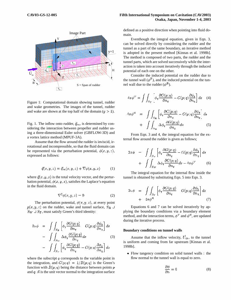
Figure 1: Computational domain showing tunnel, rudderand wake geometries. The images of the tunnel, rudderand wake are shown at the top half of the domain ( ����� ).Fig. 1. The inflow onto rudder,
�� � � , is determined by con-sidering the interaction between propeller and rudder us-ing a three-dimensional Euler solver (GBFLOW-3D) anda vortex lattice method (MPUF-3A).
Assume that the flow around the rudder is inviscid, ir-rotational and incompressible, so that the fluid domain canbe represented via the perturbation potential, ������� ���� ,expressed as follows:
�� ������������� �� � � ����������������������������� (1)
where�� ����������� is the total velocity vector, and the pertur-
bation potential, ������������� , satisfies the Laplace’s equationin the fluid domain. ��� ��������������"! (2)
The perturbation potential, ������� ���� , at every point# ����� ���� on the rudder, wake and tunnel surface, $�%'&$�()&*$,+ , must satisfy Green’s third identity:-/. � � 010325476 � 8:9�; � #�< � �9 = 8 >?; � #�< � �59 � 89 = 8�@BA�C� 010 2ED'F ��8 9�; � #�< � �9G= 8 A�C (3)� 010 25H 6 � 8:9 ; � #�< � �9 = 8 >I; � #�< � � 9 ��89 = 8�@ A�Cwhere the subscript � corresponds to the variable point inthe integration, and ; � #�< � �J�K�ML/N�� #�< � � is the Green’sfunction with N�� #�< � � being the distance between points #and � .
�= is the unit vector normal to the integration surface
defined as a positive direction when pointing into fluid do-main.
Eventhough the integral equation, given in Eqn. 3,can be solved directly by considering the rudder and thetunnel as a part of the same boundary, an iterative methodis adopted in the present method [Kinnas et al. 1998b].The method is composed of two parts, the rudder and thetunnel parts, which are solved successively while the inter-action is taken into account iteratively through the inducedpotential of each one on the other.
Consider the induced potential on the rudder due tothe tunnel wall ( � + ), and the induced potential on the tun-nel wall due to the rudder ( � % ).O . � + � 0P0 2 H 6 ��8 9�; � #�< � �9 = 8 >?; � #�< � � 9 ��89G= 8 @QA�C (4)
O . � % � 0P0 2 4 6 � 8 9�; � #�< � �9 = 8 >?; � #�< � �E9 ��89G= 83@ A�C� 0P0R2ED F � 8:9�; � #�< � �9 = 8 A�C (5)
From Eqn. 3 and 4, the integral equation for the ex-ternal flow around the rudder is given as follows;-/. � � 0S0 254 6 � 8 9�; � #�< � �9 = 8 >?; � #�< � � 9 ��89 = 8 @TA�C� 0S0R2 D F ��8 9�; � #�< � �9G= 8 A�C � O . � + (6)
The integral equation for the internal flow inside thetunnel is obtained by substituting Eqn. 5 into Eqn. 3.-/. � � 010 25H 6 � 8:9 ; � #�< � �9 = 8 >I; � #�< � � 9 ��89 = 8�@ A�C� O . � % (7)
Equations 6 and 7 can be solved iteratively by ap-plying the boundary conditions via a boundary elementmethod, and the interaction terms, � + and � % , are updatedduring the iterative process.
Boundary conditions on tunnel walls
Assume that the inflow velocity,�U � � , to the tunnel
is uniform and coming from far upstream [Kinnas et al.1998b].V
Flow tangency condition on solid tunnel walls : theflow normal to the tunnel wall is equal to zero.9 �9 = �W! (8)

CAV03-GS-12-005 Fifth International Symposium on Cavitation (CAV2003)Osaka, Japan, November 1-4, 2003V
Inflow and outflow boundary conditions: the total ve-locity normal to the inlet/outlet boundaries is equal touniform inflow,
�U � � .
�U ����� �= �7��� � �= � �U ����� �=��� 9 �9 = � ! (9)
Boundary conditions on cavitating rudder
Figure 2 shows boundary conditions on cavitatingrudder, and the definition of local coordinates. The appliedboundary conditions are as follows:V
Kinematic boundary condition on wetted surface: theflow is tangent to the rudder surfaces.9 �9 = � �� ����� �= (10)VKutta condition: the velocity at the rudder trailingedge has to be finite.
� ��� ��� �� ���� ���(11)V
Cavity closure condition: the cavity closes at the cav-ity end. This condition requires iterative solutionmethod to find the cavity planform [Kinnas and Fine1993]. � ��� ������W! (12)
where�
is the cavity height at the cavity trailing edgeand is a function of cavity length, � , and cavitationnumber, � .VKinematic boundary condition on cavity surface: thetotal velocity normal to the cavity surface requires tobe zero. The kinematic boundary condition leads tothe following partial differential equation for the cav-ity height calculation [Kinnas and Fine 1993].
9 �9,C � ��� > � �"!# ��$&% � 9 �9(' � ��$ >)� �*!# ����% � � �!,+.- � #(13)where
�is the cavity height normal to the rudder sur-
face. C ' and = denote the non-orthogonal curvilinearcoordinates defined on rudder surface, and
� � � $ and� � are the total velocities of C ' and = directions, re-spectively.VDynamic boundary condition on cavity surface: thedynamic boundary condition on the cavitating rudderand wake surfaces requires the pressure everywhereon the cavity to be constant and equal to the vaporpressure, / $ . Since Bernoulli’s constant increases
s
v n
ψyshaft
qsqc
qin
Kinematic BC
Dynamic BC
Cavity closure condition
Kutta condition
Figure 2: Boundary conditions on cavitating rudder sub-ject to the propeller induced inflow, and the definition oflocal coordinates.
across the propeller plane, Bernoulli’s equation can-not directly apply between points on the rudder andthe points upstream of the propeller. In the presentwork, Bernoulli’s equation is applied between a pointon the cavity surface with a vertical coordinate, � , anda point with a vertical coordinate, � � , far downstreamalong the same streamline where the velocity mag-nitude is � � and the pressure # � [Kinnas et al. 2003;Natarajan 2003]. The velocity � � and the pressure # �far downstream are determined from GBFLOW-3D.# $ �10 - � �2 � 0*3 ��� # � �40 - � �� � 0*3 � � (14)
Since the pressure variation far downstream, as pre-dicted by GBFLOW-3D (in which the pressures donot include the hydrostatic pressure) is small 5 as de-scribed in [Kinnas et al. 2003; Natarajan 2003], wecan assume that the pressure far downstream is prac-tically only due to hydrostatic effects.
# $ � 0 - � �2 � 0*3 ��� # �7698;:=< � 0 - � �� � 0*3 � �,6&8>:>< (15)
where # �,6&8>:>< is the absolute pressure at the propellershaft axis and � �7698;:=< is the vertical coordinate of theshaft axis.
By combining Eqn. 14 and 15 and non-dimensionalizing with 0
� ��76 �@? L - , the cavity velocityon the rudder is defined as following:AThe range of the pressures predicted by GBFLOW-3D can also be
seen in Fig.19.

CAV03-GS-12-005 Fifth International Symposium on Cavitation (CAV2003)Osaka, Japan, November 1-4, 2003
� 2�(�76 � ? � � �� ��(�76 � ?�� � � � ��R� (16)
where� �76 �@? is the ship speed. � ��3� is the local cav-
itation number at a vertical coordinate � and is givenas:
� ���R� ��� % > -3� > � �7698;:=<� ��76 � ? (17)
and the rudder cavitation number � % is,
�:% � # �,6&8>:>< > # $� � � ��76 �@? (18)
From Bernoulli’s equation and the definition of totalcavity velocity on the non-orthogonal local coordi-nates, the expression for the unknown chordwise per-turbation velocity, ���� � , can be derived with assump-tion that
�� � is equal to�� � � :
9 �9,C � > ���� ��� �C � � $ � �"!# � ! +.- # � �2 > � �$ (19)
where # is the angle between C and ' directions.
Equation 19 is integrated to form a Dirichlet typeboundary condition for perturbation potential � overthe cavity surface [Kinnas and Fine 1993].VCavity detachment condition: the cavity detachmentlocation is determined iteratively until the follow-ing smooth detachment condition is satisfied [Young2002].
1. The cavity has non-negative thickness at itsleading edge.
2. The pressure on the wetted portion of the rudderupstream of the cavity should be greater than thevapor pressure.
Three-dimensional steady Euler solver
A three-dimensional steady Euler solver, namedGBFLOW-3D, is used to solve the flow around the pro-peller and tunnel in the absence of rudder. GBFLOW-3Duses a finite volume method and the artificial compress-ibility method [Chorin 1967]. The details on this methodare described in [Choi 2000; Choi and Kinnas 2001].
The dimensionless continuity and the momentumequations can be expressed as following:
9��9� �� � 9��9 � � 9��9 � � 9��9 � ��� (20)
where U, F, G, H, and Q are defined as follows.
� � ���� # �'����� � �!����
� L�"� � � #�'� �
���� � � ���� ' L�"� '' � � #
' �� �� � � ���� � L�"� �
' �� � � #� ��
� � ���� !#%$#%&#%'� �� (21)
where " is the artificial compressibility factor. A vertexbased scheme [Choi and Kinnas 2001], Ni’s lax-Wendroffmethod [Ni 1982] for the time discretization, and a fourthorder artificial viscosity were adapted to solve the govern-ing equation (Eqn. 20).
The body force distribution on the finite volume cellswhich correspond to the location of blade can be obtainedby the integration of the pressure difference across theblade surface,
F # , over the area of the lifting surface. Thedimensionless three-dimensional body force can be calcu-lated by the following formula [Choi and Kinnas 2001].
�#%(*) � � O+ 2-, �� � �.0/(22)
where�. /
is the dimensionless pressure force obtainedfrom the propeller potential flow solver (MPUF-3A).
+ 2 isthe cell volume, and , � is the advance ratio based on shipspeed. In [Choi and Kinnas 2001] the body force was var-ied in the circumferential direction according to the pro-peller loading at the same blade angle. This body forcecan be considered as the time average of the body force ata point in space in the case of non-axisymmetric nominalinflow.
Boundary conditions
The boundaries of computational domain and the ap-plied boundary conditions in Euler solver are shown inFig. 3. Eventhough the rudder is shown in Fig. 3, the rud-der is not modeled in Euler solver. The boundary condi-tions applied in this problem are as follows:V
Upstream boundary: the velocities are equal to thegiven values, and the derivative of the pressure withrespect to the axial direction is set to zero.� � ' � � � � � ' � �21 � $-3 � (23)9 #9 = � 9 #9 � �"! (24)

CAV03-GS-12-005 Fifth International Symposium on Cavitation (CAV2003)Osaka, Japan, November 1-4, 2003
Tunnel Bottom Wall
Tunnel Top Wall
Dow
nstr
eam
Bou
ndar
y
n
n
n
n
UinCenter line
i-indexj-
inde
x
q . n = 0
∂( p, qt ) / ∂n = 0
∂(u,
v,w
,p)
/∂n
=0
q . n = 0
∂( p, qt ) / ∂n = 0
Ups
trea
mB
ound
ary
U = Uin
∂p / ∂ n = 0
Figure 3: Boundary conditions for the Euler solver, andpropeller and rudder arrangement in computational do-main:
�� � � � ' � � is the total velocity.�� < , and
�� � arethe tangential and the normal components of the total ve-locity, i.e.
�� � �� � � �� < .VDownstream boundary: the first derivatives of the ve-locities and the pressure with respect to axial direc-tion are set to zero.9 � � ' � # �9 = � 9 � � ' � # �9 � � ! (25)VTunnel wall boundary: the normal component of thevelocity is equal to zero, and the first derivatives ofvelocity and pressure with respect to the directionnormal to the tunnel wall are taken equal to zero.9 � # �� < �9 = �"! (26)
�� � �= �"! (27)
where�� is the total velocity defined as
�� � � � ' � � ,and
�� < is the tangential component of the total veloc-ity.
Multi-block method
Since the effect of the rudder on the propeller couldbe significant in the case the blockage effects due to therudder alter the inflow to the propeller, the propeller-rudder interaction needs to be considered. In this paper,the propeller-rudder interaction is evaluated by using amulti-block approach in Euler solver. As shown in Fig. 4,the multi-block method divides the fluid domain into twoblocks, i.e., one block for the flow around the propellerrepresented by body force and another block for the flowaround the rudder represented as a solid boundary [Natara-jan 2003]. The overlapping zone is introduced to improvethe convergence of the iterative process between the twoblocks. Two blocks communicate to each other throughthe exchange of velocities and pressure.
Rudder
Propeller
Tunnel Top Wall
Tunnel Top Wall
Tunnel Bottom Wall
Tunnel Bottom Wall
Infl
ow
Out
flow
plan
eto
BL
OC
K-1
Infl
owpl
ane
toB
LO
CK
-2
Out
flow
u,v,w,p
u,v,w,p
BLOCK-2
BLOCK-1
OV
ER
LA
PP
ING
ZO
NE
Figure 4: Two blocks used in the 3-D Euler solver
y
z
-4 -2 0 2 4-4
-3
-2
-1
0
1
2
3
4
Figure 5: Cylindrical grid used in block- � at the inflowplane for block-
-(as shown in Figure 4). Looking from
downstream.
The multi-block method is composed of two itera-tive processes: An iteration between the propeller solver(MPUF-3A) and the 3-D Euler solver, and an iteration be-tween block-1 and block-2. A cylindrical grid is used inblock-1 (Fig. 5) to accommodate the body force cells rep-resenting the propeller, whereas an H-type adapted grid isused to model the rudder in block-2 (Fig. 6).
The iterative process between block-1 and block-2 isas follows:V
In block-1
– Perform the propeller analysis using the mea-sured nominal wake as the inflow, and find theloading of propeller (MPUF-3A).
– Solve the velocity flow field by using the

CAV03-GS-12-005 Fifth International Symposium on Cavitation (CAV2003)Osaka, Japan, November 1-4, 2003
y
z
-4 -2 0 2 4-4
-3
-2
-1
0
1
2
3
4
Figure 6: H-type grid used in block--
at the outflow planefor block- � (as shown in Figure 4). Looking from down-stream.
body forces computed from the propeller solver(MPUF-3A).
– Compute the effective wake by subtracting theinduced velocity from the total velocity ob-tained from the Euler method.
– Interpolate velocities and pressure along theoverlapping zone into the inflow boundary forblock-2.V
In block-2
– Compute the velocity flow field around rudderusing the interpolated inflow conditions.
– Interpolate velocities and pressure into the out-flow boundary for block-1.V
Solve block-1 problem using the computed effectivewake for MPUF-3A run, and update the propellerloading.VDo iterations between block-1 and block-2 until thepropeller loading converges.
VALIDATIONS AND RESULTS
Convergence studies
In order to validate the present method, the sensitiv-ity of the solution to varying number of panels is studiedfor a cavitating rudder subject to the flow field shown inFigs. 7 and 8. The flow field shown in Figs. 7 and 8 is eval-uated from the iterative runs between GBFLOW-3D andMPUF-3A, and tunnel walls are modeled as solid bound-aries in GBFLOW-3D, and using quadrilateral panels inPROPCAV. The dimensions of the computational domain
X
Y
Z
U: 0.500 0.610 0.720 0.830 0.940 1.050 1.160 1.270 1.380 1.490 1.600
TUNNEL DIMENSIONYTOP = 1.756R, YBOT = -1.756R, ZSIDE = ±3.5R
Figure 7: Axial velocity (
�) contours at the center-plane
of the domain as predicted by GBFLOW-3D/MPUF-3A inthe absence of rudder: uniform inflow.
and half of its grid are shown in Fig. 9. The tunnel top wallis located at � �1� ������� N (R = propeller radius), and thetunnel bottom wall is located at �)� > � ������� N . The mid-chord line of the rudder is located at � � � � O -� O N down-stream of propeller, and the span of the rudder is extendedfrom tunnel top wall to � � > � � ! � N . The cavitation num-ber, � % � - � ! , and Froude number,
. %� � � � � , are usedfor the convergence tests. The rudder turning angle, �is
-� toward the starboard side. The convergence of the
circulation distribution of the cavitating rudder with vary-ing spanwise and chordwise number of panels is shown inFigs. 10 and 11, respectively. A full-cosine spacing alongthe chordwise direction and the uniform spacing along thespanwise direction are used for paneling of the rudder. Asshown in Figs. 10 and 11, the circulation distribution con-verges very quickly with number of chordwise and span-wise panels. Figure 12 depicts the convergence of cavityvolume with number of panels on the rudder. As shown inthe figure, the cavity volume prediction is somewhat sen-sitive to the number of panels. The dependence of cavityplanforms on the panel discretization is shown in Fig. 13,where the cavity planforms are shown not to be much sen-sitive to the number of panels.
Validation with experiment
The predicted cavity patterns are compared with thoseobserved from the experiments to validate the numerics ofthe present method. The experiment has been conductedfor a horn-type rudder in the presence of a 6-bladed pro-peller inside a cavitation tunnel. Figure 14 depicts the di-mension and the arrangement of propeller, rudder and cav-itation tunnel.
In the experiment, the propeller operates at a de-���������������� � �"!$# . ! is the gravitational force and # is the span of
rudder.

CAV03-GS-12-005 Fifth International Symposium on Cavitation (CAV2003)Osaka, Japan, November 1-4, 2003
X
Y
Z
W: -0.600 -0.480 -0.360 -0.240 -0.120 0.000 0.120 0.240 0.360 0.480 0.600
TUNNEL DIMENSIONYTOP = 1.756R, YBOT = -1.756R, ZSIDE = ±3.5R
Figure 8: Circumferential velocity ( � ) contours at thecenter-plane of the domain as predicted by GBFLOW-3D/MPUF-3A in the absence of rudder: uniform inflow.
X
Y
Z
TUNNEL DIMENSIONYTOP = 1.756R, YBOT = -1.756RZSIDE = ±3.5R
Figure 9: Computational domain used in GBFLOW-3D/MPUF-3A with the tunnel walls and the propeller.
y / S
Γ
0 0.2 0.4 0.6 0.8 1-2
-1.5
-1
-0.5
0
0.5
1
1.5
2
2.5
3
3.5
60 x 1060 x 2060 x 3060 x 4060 x 50
Sy = 0
y = STunnel Top Wall
Figure 10: Convergence of circulation distribution on cav-itating rudder with spanwise number of panels: � % � - � ! ,. % � � ��� , and � � -
.
y / S
Γ
0 0.2 0.4 0.6 0.8 1-2
-1.5
-1
-0.5
0
0.5
1
1.5
2
2.5
3
3.5
40 x 4050 x 4060 x 4070 x 4080 x 40
Sy = 0
y = STunnel Top Wall
Figure 11: Convergence of circulation distribution on cavi-tating rudder with chordwise number of panels: � % � - � ! ,. % � � ��� , and �I� -�
.
Number of Panels
Cav
ityvo
lum
e*
103
0 500 1000 1500 2000 2500 3000 35000
0.2
0.4
0.6
0.8
1
Figure 12: Convergence of cavity volume on the rudderwith number of panels: �G% � - � ! ,
. % � � � � , and �I� - .

CAV03-GS-12-005 Fifth International Symposium on Cavitation (CAV2003)Osaka, Japan, November 1-4, 2003
Y
X
Z
60 x 20
Y
X
Z
80 x 40
Y
X
Z
60 x 40
Y
X
Z
60 x 50
Figure 13: Convergence of cavity planform on the rudderwith number of panels: � % � - � ! ,
. % � � � � , and � � -� .
sign advance ratio of , � � ! � � � with thrust coefficient,� + � ! � - !R� - . In this computation, the propeller ad-vance ratio is adjusted so that the resulting thrust coef-ficient matches the value of the design thrust coefficientmeasured from experiment. The advance ratio correspond-ing to the design
� + � ! � - !:� - is determined throughtrial and error, and , � �K� � ! � is used for the computa-tion. The measured nominal axial velocity at the propellerplane is shown in Fig. 15. The effective wake predicted byGBFLOW-3D and MPUF-3A is shown in Fig. 16, wherethe interaction between the propeller and the tunnel is in-cluded in an iterative manner. The axial and circumfer-ential velocity contours at the center plane of the domainare shown in Figs. 17 and 18, respectively. As shown inFig. 18, the circumferential velocity varies from positivebelow the propeller shaft to negative above the propellershaft axis over the rudder in the propeller slipstream. Thepredicted pressure contours are shown in Fig. 19, wherethe expected pressure jump across the propeller plane isclearly shown in the figure.
Figures 20 and 21 show the observed and the pre-dicted cavity patterns at the cavitation numbers, � % �� � - O and � � � � , and the rudder turning angle, �7� �
. Therudder turning angle toward the starboard side is consid-ered to be positive in the experiment. As shown in the fig-ures, the predicted cavity patterns are well compared withthose observed.
The effect of propeller and tunnel walls onrudder cavitation
The effect of propeller and tunnel walls on ruddercavitation is shown in Fig. 22. The inflow to the rudderin the case of with tunnel and propeller effect is shown in
1.0R
1.43R
1.07R
3.5265R
3.5265R
RudderPropeller
Tunnel Top Wall
Tunnel Bottom Wall
Figure 14: Configuration of propeller and horn type rudderinside of a tunnel.
UX1.00
0.92
0.84
0.76
0.68
0.60
0.52
0.44
0.36
0.28
0.20
Figure 15: Axial velocity contours of nominal wake mea-sured from experiment.
UX1.00
0.92
0.84
0.76
0.68
0.60
0.52
0.44
0.36
0.28
0.20
Figure 16: Axial velocity contours of effective wake pre-dicted from GBFLOW-3D/MPUF-3A run: the effectivewake is computed at � � > ! � location.

CAV03-GS-12-005 Fifth International Symposium on Cavitation (CAV2003)Osaka, Japan, November 1-4, 2003
X
Y
Z
U1.100
1.040
0.980
0.920
0.860
0.800
0.740
0.680
0.620
0.560
0.500
TUNNEL DIMENSION
YTOP = 2.4045RYBOT = -4.6485RZSIDE = ±3.5265R
Figure 17: Axial velocity (
�) contours at the center-plane
of the domain as predicted by GBFLOW-3D/MPUF-3A inthe absence of rudder.
X
Y
Z
W0.350
0.280
0.210
0.140
0.070
0.000
-0.070
-0.140
-0.210
-0.280
-0.350
TUNNEL DIMENSION
YTOP = 2.4045RYBOT = -4.6485RZSIDE = ±3.5265R
Figure 18: Circumferential velocity ( � ) contours at thecenter-plane of the domain as predicted by GBFLOW-3D/MPUF-3A in the absence of rudder.
X
Y
Z
P0.150
0.115
0.080
0.045
0.010
-0.025
-0.060
-0.095
-0.130
-0.165
-0.200
TUNNEL DIMENSION
YTOP = 2.4045RYBOT = -4.6485RZSIDE = ±3.5265R
Figure 19: Pressure contours at the center-plane of the do-main as predicted by GBFLOW-3D/MPUF-3A in the ab-sence of rudder. The shown pressure does not include thehydrostatic terms.
X
Y
Z σR = 1.24
α = 5o
Figure 20: Comparison of cavity patterns observed fromexperiment (top) and predicted by PROPCAV (bottom)with tunnel effect: � % � � � - O ,
. % � � � � , and �I� � .

CAV03-GS-12-005 Fifth International Symposium on Cavitation (CAV2003)Osaka, Japan, November 1-4, 2003
X
Y
ZσR = 1.65
α = 5o
Figure 21: Comparison of cavity patterns observed fromexperiment (top) and predicted by PROPCAV (bottom)with tunnel effect: �G%?� � � � � ,
. % � � ��� , and � � � .
Y
X
Z
(a) Without propeller and without tunnel Effect
Y
X
Z
(b) with propeller and without tunnel effect
Y
X
Z
(c) with propeller and with tunnel effect
Y
X
Z
(d) with propeller and with tunnel effect(tunnel width reduced to half)
Figure 22: Comparison of the cavity patterns predicted byPROPCAV with/without propeller and/or tunnel effect: (a)without propeller and without tunnel effect, (b) with pro-peller and without tunnel effect, (c) with propeller and withtunnel effect, and (d) with propeller and with tunnel effectwith reduced tunnel width by half; � % � � � - O ,
. % � � ��� ,and �I� �
Figs. 17 and 18. The variation of circumferential velocityinduces varying angle of attack to the rudder section, andthat changes the loading on the rudder, as shown in Fig. 23.The rudder loading below the propeller shaft increases dueto the positive circumferential velocity, and as a result ofthat, the cavity extent increases. On the other hand, thecavity disappears above the propeller shaft axis (Fig. 22-(b) and (c)). As the tunnel side wall distance decreases,the sheet cavity grows over the rudder (Fig. 22-(d)) due tothe increased loading of the flow.
Validation of Multi-block scheme
The propeller-rudder interaction is performed for ahorn-type rudder with NACA00 thickness form and
- !��thickness to chord ratio. The computational domain usedis shown in Fig. 24. In Fig. 25 the axial velocity distri-bution is shown along the center plane, where the effectof the rudder is clearly shown. Figure 26 shows the cir-cumferential velocity contours along the center plane forboth blocks. From this figure it can be seen clearly that thevortical flow induced by the propeller is canceled down-stream of the rudder trailing edge. The presence of therudder causes a decrease in the axial velocity at an axiallocation upstream of the rudder. The convergence of thepropeller thrust and the torque coefficients with number ofiterations is shown in Fig. 27.

CAV03-GS-12-005 Fifth International Symposium on Cavitation (CAV2003)Osaka, Japan, November 1-4, 2003
y / S
Γ
0 0.2 0.4 0.6 0.8 10
0.5
1
1.5
2
2.5
3
3.5
4 Rudder onlyWith Propeller effect, No tunnelWith Propeller and Tunnel effectWith Propeller and Tunnel (half width) effect
Figure 23: Comparison of the circulation distribution pre-dicted by PROPCAV with/without propeller and/or tunneleffect: (a) without propeller and without tunnel effect, (b)with propeller and without tunnel effect, (c) with propellerand with tunnel effect, and (d) with propeller and with tun-nel effect with reduced tunnel width by half; � % � � � - O ,. %?� � ��� , and � � �
BLOCK-2Outflow planeto BLOCK-1
Tunnel Top Wall
Inflow planeto BLOCK-2
BLOCK-1
Tunnel Top Wall
Figure 24: 3-D Euler solver grid showing horn-type rudderwith NACA0020 section.
U1.50
1.43
1.36
1.29
1.22
1.15
1.08
1.01
0.94
0.87
0.80
Inflow planeto BLOCK-2
BLOCK-1 BLOCK-2Outflow planeto BLOCK-1
Figure 25: Axial velocity (
�) contours on the center plane
of block-1 and 2 for a horn-type rudder.
BLOCK-2Outflow planeto BLOCK-1
W0.40
0.32
0.24
0.16
0.08
0.00
-0.08
-0.16
-0.24
-0.32
-0.40
Inflow planeto BLOCK-2
BLOCK-1
Figure 26: Circumferential velocity ( � ) contours on thecenter plane of block-1 and 2 for a horn-type rudder.

CAV03-GS-12-005 Fifth International Symposium on Cavitation (CAV2003)Osaka, Japan, November 1-4, 2003
No. of iterations
KT,
10K
Q
0 1 2 3 4 5 60
0.2
0.4
0.6
KT
10KQ
Figure 27: Convergence of propeller forces with the num-ber of iterations.
CONCLUSIONS
A low-order boundary element method (PROPCAV),a vortex-lattice method (MPUF-3A) and a steady three-dimensional Euler solver (GBFLOW-3D) have been cou-pled to predict the sheet cavitation over the rudder sub-ject to an inflow induced by propeller inside a tunnel. It-erations between GBFLOW-3D and MPUF-3A were per-formed to predict the effective wake to the propeller andthe new loading on the propeller. The tunnel walls weretreated as solid boundaries, and the rudder was not mod-eled in GBFLOW-3D. The propeller total flow field wascomputed by GBFLOW-3D at the rudder control points.The rudder sheet cavitation was predicted by PROPCAVusing the inflow induced by propeller, and the effect of thetunnel walls were considered in an iterative manner.
The present method was validated by performing theseveral convergence studies with varying number of pan-els, and by comparing the predicted cavity patterns withthose observed in an experiment at a cavitation tunnel. Thepredicted cavity patterns by the present method comparedwell with those observed in the experiment. The multi-block scheme which accounts for the two-way interactionbetween the rudder and the propeller was also developedand preliminary results were presented.
ACKNOWLEDGMENT
Support for this research was provided by Phase IIIof the “Consortium on Cavitation Performance of HighSpeed Propulsors” with the following members: AB VolvoPenta, American Bureau of Shipping, El Pardo ModelBasin, Hyundai Maritime Research Institute, Kamewa AB,Michigan Wheel Corporation, Naval Surface Warfare Cen-
ter Carderock Division, Office of Naval Research (Con-tract N000140110225), Ulstein Propeller AS, VA TechEscher Wyss GMBH, W �
� rtsil �� Propulsion Norway, and
W �� rtsil �
� Propulsion Netherlands.
References
Achkinadze, A. S., Berg, A., Krasilnikov, V. I., andStepanov, I. E. (2003). Numerical analysis of pod-ded and steering system using a velocity based sourceboundary element method with modified trailing edge.In Propellers/Shafting 2003 Symposium, pages 1–22(paper No. 12), Virginia Beach, VA. Soc. Naval Arch.& Marine Engnrs.
Breslin, J. P., Van Houten, R. J., Kerwin, J. E., andJohnsson, C.-A. (1982). Theoretical and experimentalpropeller-induced hull pressures arising from intermit-tent blade cavitation, loading, and thickness. Trans.of Society of Naval Architects & Marine Engineers,90:111–151.
Choi, J.-K. (2000). Vortical Inflow – Propeller InteractionUsing Unsteady Three-Dimensional Euler Solver. PhDthesis, Department of Civil Engineering, The Universityof Texas at Austin.
Choi, J.-K. and Kinnas, S. A. (1998). A 3-D Euler Solverand Its Application on the Analysis of Cavitating Pro-pellers. In 25th American Towing Tank Conference,Iowa City, IA.
Choi, J.-K. and Kinnas, S. A. (2000a). Non-axisymmetriceffective wake prediction by using an unsteady three-dimensional Euler solver. In Propellers/Shafting ’00Symposium, Virginia Beach, VA. Soc. Naval Arch. &Marine Engnrs.
Choi, J.-K. and Kinnas, S. A. (2000b). An unsteady three-dimensional euler solver coupled with a cavitating pro-peller analysis method. In The 23rd Symposium onNaval Hydrodynamics, Val de Reuil, France.
Choi, J.-K. and Kinnas, S. A. (2001). Prediction of non-axisymmetric effective wake by a 3-D Euler solver.Journal of Ship Research, 45(1):13–33.
Choi, J.-K. and Kinnas, S. A. (2003). Prediction of un-steady effective wake by a euler solver/vortex-latticecoupled method. Journal of Ship Research, 47(2):131–144.
Chorin, A. J. (1967). A numerical method for solving in-compressible viscous flow problems. Journal of Com-putational Physics, 2:pp.12–26.

CAV03-GS-12-005 Fifth International Symposium on Cavitation (CAV2003)Osaka, Japan, November 1-4, 2003
Fine, N. E. (October, 1992). Nonlinear Analysis of Cavi-tating Propellers in Nonuniform Flow. PhD thesis, De-partment of Ocean Engineering, MIT.
Fine, N. E. and Kinnas, S. A. (1993a). A boundary elementmethod for the analysis of the flow around 3-d cavitatinghydrofoils. Journal of Ship Research, 37:213–224.
Fine, N. E. and Kinnas, S. A. (1993b). The nonlinear nu-merical prediction of unsteady sheet cavitation for pro-pellers. In Sixth International Conference On Numeri-cal Ship Hydrodynamics, pages 531–544, University ofIowa, Iowa.
Han, J., Kong, D., Kim, Y., and Lew, J. (1999). Analysisof propeller-rudder interaction with rudder angle. An-nual Autumn Meeting of SNAK, Taejon, Korea, pagespp. 206–209.
Han, J., Kong, D., Song, I.-H., and Lee, C.-S. (2001).Analysis of cavitating flow around the horn-type rudderin the race of a propeller. Fourth International Sympo-sium on Cavitation, California Institute of Technology,Pasadena, CA USA, CAV2001:sessionB9.005.
Kerwin, J. E., Kinnas, S. A., Wilson, M. B., and J., M.(1986). Experimental and analytical techniques for thestudy of unsteady propeller sheet cavitation. In Six-teenth Symposium on Naval Hydrodynamics, Berkeley,California.
Kerwin, J. E. and Lee, C.-S. (1978). Prediction of Steadyand Unsteady Marine Propeller Performance by Numer-ical Lifting-Surface Theory. Trans. of Society of NavalArchitects & Marine Engineers, 86:218–253.
Kinnas, S. A. (1985). Non-linear corrections to the lineartheory for the prediction of the cavitating flow aroundhydrofoils. Technical Report 85-10, MIT, Departmentof Ocean Engineering.
Kinnas, S. A. (1991). Leading-edge corrections to the lin-ear theory of partially cavitating hydrofoils. Journal ofShip Research, 35(1):pp. 15–27.
Kinnas, S. A., Choi, J.-K., Kosal, E. M., Young, Y. L., andLee, H. S. (1999). An integrated computational tech-nique for the design of propellers with specified con-straints on cavitation extent and hull pressure fluctua-tions. In CFD99 - The International CFD Conference,Ulsteinvik, Norway.
Kinnas, S. A., Choi, J.-K., Lee, H. S., and Young, Y. L.(2000). Numerical cavitation tunnel. In NCT50, In-ternational Conference on Propeller Cavitation, pages137–157, Newcastle upon Tyne, England.
Kinnas, S. A. and Fine, N. E. (1989). Theoretical predic-tion of the midchord and face unsteady propeller sheetcavitation. In Fifth International Conference on Numer-ical Ship Hydrodynamics, pages 685–700, Hiroshima,Japan.
Kinnas, S. A. and Fine, N. E. (1992). A nonlinear bound-ary element method for the analysis of unsteady pro-peller sheet cavitation. In Nineteenth Symposium onNaval Hydrodynamics, pages 717–737, Seoul, Korea.
Kinnas, S. A. and Fine, N. E. (1993). A numerical non-linear analysis of the flow around 2-d and 3-d par-tially cavitating hydrofoils. Journal of Fluid Mechanics,254:151–181.
Kinnas, S. A., Griffin, P. E., Choi, J.-K., and Kosal, E. M.(1998a). Automated design of propulsor blades forhigh-speed ocean vehicle applications. Trans. of Societyof Naval Architects & Marine Engineers, 106:213–240.
Kinnas, S. A., Griffin, P. E., and Mueller, A. C. (1997).Computational tools for the analysis and design of highspeed propulsors. In The International CFD Confer-ence, Ulsteinvik, Norway.
Kinnas, S. A., Lee, H. S., and Mueller, A. C. (1998b). Pre-diction of propeller blade sheet and developed tip vortexcavitation. In 22nd Symposium on Naval Hydrodynam-ics, pages 182–198, Washington, D.C.
Kinnas, S. A., Natarajan, S., Lee, H. S., Kakar, K., andGupta, A. (2003). Numerical modeling of poddedpropulsors and rudder cavitation. In Propellers/Shafting2003 Symposium, pages 1–20 (paper No. 5), VirginiaBeach, VA. Soc. Naval Arch. & Marine Engnrs.
Kudo, T. and Kinnas, S. A. (1995). Application of un-steady vortex/source lattice method on supercavitatingpropellers. In 24th American Towing Tank Conference,pages 33–40, Texas A&M University.
Lee, C. (1979). Prediction of Steady and Unsteady Per-formance of Marine Propellers with or without Cavita-tion by Numerical Lifting Surface Theory. PhD thesis,M.I.T., Department of Ocean Engineering.
Lee, C.-S. (1981). Prediction of the transient cavitation onmarine propellers. In Thirteenth Symposium on NavalHydrodynamics, pages 41–64, Tokyo, Japan.
Lee, H. S. (2002). Modeling of Unsteady Wake Alignmentand Developed Tip Vortex Cavitation. PhD thesis, De-partment of Civil Engineering, The University of Texasat Austin.

CAV03-GS-12-005 Fifth International Symposium on Cavitation (CAV2003)Osaka, Japan, November 1-4, 2003
Lee, H. S., Gu, H., Natarajan, S., and Kinnas, S. A. (2003).MPUF-3A (version 2.1) user’s manual. Ocean Engi-neering Report 03-2, Ocean Engineering Group, UTAustin, Austin, TX.
Lee, H. S. and Kinnas, S. A. (2001). Modeling of unsteadyblade sheet and developed tip vortex cavitation. In CAV2001: Fourth International Symposium on Cavitation,Pasadena, CA. California Institute of Technology.
Lee, H. S. and Kinnas, S. A. (2003). Application of bem inthe prediction of unsteady blade sheet and developed tipvortex cavitation on marine propellers. Journal of ShipResearch, Accepted for publication.
Mueller, A. C. (1998). Development of face and mid-chordcavitation models for the prediction of unsteady cavita-tion on a propeller. Master’s thesis, UT Austin, Dept. ofCivil Engineering.
Mueller, A. C. and Kinnas, S. A. (1997). Cavitation pre-dictions using a panel method. In ASME Symposium onMarine Hydrodynamics and Ocean Engineering, vol-ume 14, pages 127–137, Dallas, TX.
Mueller, A. C. and Kinnas, S. A. (1999). Propeller sheetcavitation predictions using a panel method. Journal ofFluids Engineering, 121:282–288.
Natarajan, S. (2003). Computational modeling of rud-der cavitation and propeller/rudder interaction. Master’sthesis, The University of Texas at Austin.
Ni, R.-H. (1982). A multiple-grid scheme for solving theEuler equations. AIAA Journal, 20(11):pp.1565–1571.
Shen, Y., Remmers, K., and Jiang, C. W. (1997). Effectsof ship hull and propeller on rudder cavitation. Journalof Ship Research, Vol. 41, No. 3, pp.172 180.
Tamashima, M., Matsui, S., Yang, J., Mori, K., and Ya-mazaki, R. (1993). The method for predicting the per-formance of propeller-rudder system with rudder anglesand its application to the rudder design. Transaction ofthe West-Japan Society of Naval Architects, 86:pp. 53–76 (in Japanese).
Tulin, M. P. and Hsu, C. C. (1980). New applications ofcavity flow theory. In 13th Symposium on Naval Hydro-dynamics, Tokyo, Japan.
Uhlman, J. S. (1987). The surface singularity method ap-plied to partially cavitating hydrofoils. Journal of ShipResearch, 31(No. 2):107–124.
Young, Y. L. (2002). Numerical Modeling of Supercavi-tating and Surface-Piercing Propellers. PhD thesis, De-partment of Civil Engineering, The University of Texasat Austin.
Young, Y. L. and Kinnas, S. A. (1999). Numerical and ex-perimental validation of a cavitating propeller bem code.In Cavitation and Multiphase Flow Forum, San Fran-sisco, CA. 3rd ASME/JSME Joint Fluids EngineeringConference.
Young, Y. L. and Kinnas, S. A. (2001). A bem for the pre-diction of unsteady midchord face and/or back propellercavitation. Journal of Fluids Engineering, 123(2):311–319.
Young, Y. L. and Kinnas, S. A. (2002). A bem techniquefor the modeling of supercavitating and surface-piercingpropeller flows. In The 24rd Symposium on Naval Hy-drodynamics, Fukuoka, Japan.
Young, Y. L. and Kinnas, S. A. (2003). Numerical model-ing of supercavitating propeller flows. Journal of ShipResearch, 47(1):48–62.