nuclear criticality safety engineer training module 8 · ncset module 8 hand calculations part i...
TRANSCRIPT
NCSET Module 8 Hand Calculations Part I 1 of 11
Nuclear Criticality Safety Engineer TrainingModule 8
Hand Calculation Methods - Part IBuckling Conversion and Surface Density Methods
LESSON OBJECTIVE
This module presents two traditional hand calculation methods for estimating the critical size orsubcriticality of a system, or establishing the limiting conditions for either single fissile units orarrays of units.
REFERENCES
Many textbooks provide derivations of buckling parameters. The surface density model isdescribed in standard criticality safety references and many journal articles. A few of the readilyavailable references are listed below.
1) J. J. Duderstadt and L. J. Hamilton, Nuclear Reactor Analysis, John Wiley and Sons,Inc., New York (1976).
2) Ronald Allen Knief, Nuclear Criticality Safety Theory and Practice, AmericanNuclear Society, La Grange Park, Illinois (1991).
3) J. T. Thomas, "Nuclear Safety Guide TID-7016, Revision 2," NUREG/CR-0095ORNL/NUREG/CSD-6, Oak Ridge National Laboratory (June 1978).
4) H. C. Paxton, J. T. Thomas, Dixon Callihan and E. B. Johnson, "Critical Dimensionsof Systems Containing U235, Pu239 and U233," Los Alamos Scientific Laboratory andOak Ridge National Laboratory Report TID-7028 (June 1964).
5) H. C. Paxton and N. L. Pruvost, "Critical Dimensions of Systems Containing U235,Pu239 and U233, 1986 Revision," Los Alamos National Laboratory ReportLA-10860-MS (July 1987).
BACKGROUND
Before the development of high-speed, large-memory computers, hand calculations were widelyused to establish safe limits for fissile material operations. Today these methods might seemobsolete, but they are still useful in providing a starting point for more elaborate calculations orfor providing a "sanity check" on the results of complicated computations. A preliminary reviewof a fissile material system using one or more of these methods can often provide insight into the
NCSET Module 8 Hand Calculations Part I 2 of 11
problem that may not be apparent from simply looking at a computer printout. These methodsalso have a historical importance and provide a glimpse of the early days of criticality safetycalculations.
Part I of Hand Calculation Methods discusses buckling conversions and the surface densitymodel. Part II will cover the density analog and limiting surface density methods.
BUCKLING CONVERSIONS
The buckling conversion method is based on solutions to the diffusion equation that relate thespatial neutron flux distribution in a neutron-multiplying medium to a parameter called thegeometric buckling, Bg
2. One of the earliest uses of this method was to relate the criticaldimensions of spheres, that had been measured experimentally, to those of cylinders of variousshapes (Ref. 4). Derivation of the buckling equations can be found in many nuclear engineeringtext books (e.g., Ref. 1) and will only be summarized here. A concise derivation can also befound in NCSET Module 6.
THE DIFFUSION EQUATION
The general diffusion equation in a multiplying medium is
. (1)( ) ( ) ( )D r t r t r t
v
r t
ta f∇ − + =2 1φ φ ν Σ φ
∂φ∂
( , ) , ,,
Σ
φ( ,t) is the neutron flux and the diffusion coefficient, D, in this approximation isr
(2)D s
t
=ΣΣ3 2
with the subscripts s and t indicating scattering and total cross sections, respectively.
This partial differential equation can be solved by using the separation of variables method tolook for a solution of the form
( ) ( ) ( )ϕ x t x T t, .= Ψ
Considering only one dimension, the spatial part of the diffusion equation is
(3)( ) ( ) ( )Dd
dxx
vxf a
2
2
ΨΣ Ψ Ψ+ − = −νΣ
λ
NCSET Module 8 Hand Calculations Part I 3 of 11
where λ is a constant to be determined. As in Module 6, consider a homogenous problem similarto the spatial diffusion equation,
(4)( )d
dxB x
2
22 0
ΨΨ+ =
with the boundary conditions
.Ψ Ψ′
= −
′
=
aand
a
20
20
B is an arbitrary parameter and aN represents an extrapolated dimension of the system (e.g., x + d,with d being the extrapolation distance). This problem actually has a series of solutions, but thefundamental mode is
. (5)( )Ψ x Ax
a=
′
1 cos
π
If we identify this eigenvalue problem with the space dependent diffusion equation, then
BD v f a1
2 11= + −
λν Σ Σ
or. (6)λ ν Σ1 1
2≡ + −v vDBa fΣ v
It is customary to refer to the value of B12 for the fundamental mode as the geometric buckling
,Ba
Bg12
22=
′
≡
π
where the factor π/a' is characteristic of cartesian coordinates.
By definition, the state of criticality implies a time-independent flux distribution, which in turnrequires that the fundamental eigenvalue vanish.
( )λ ν Σ1 120= = − +v vDBa fΣ
The solution becomes
( )ϕ x t A B x, cos→ ≠1 1 function of time
with the criticality condition
NCSET Module 8 Hand Calculations Part I 4 of 11
. (7)B BD
Bgf a
m12 2 2= =
−=
ν Σ Σ
MATERIAL AND GEOMETRIC BUCKLING
That is, at critical, the material buckling, Bm2, which depends on the material properties (cross
sections and atom densities) equals the geometric buckling Bg2, which depends on the geometry
(e.g., slab width, a', in one-dimension cartesian coordinates). Thus, if one knows the criticalgeometry for a sphere of a given material, the material buckling can be calculated and that can beused to determine the critical geometry for other configurations of the same material.
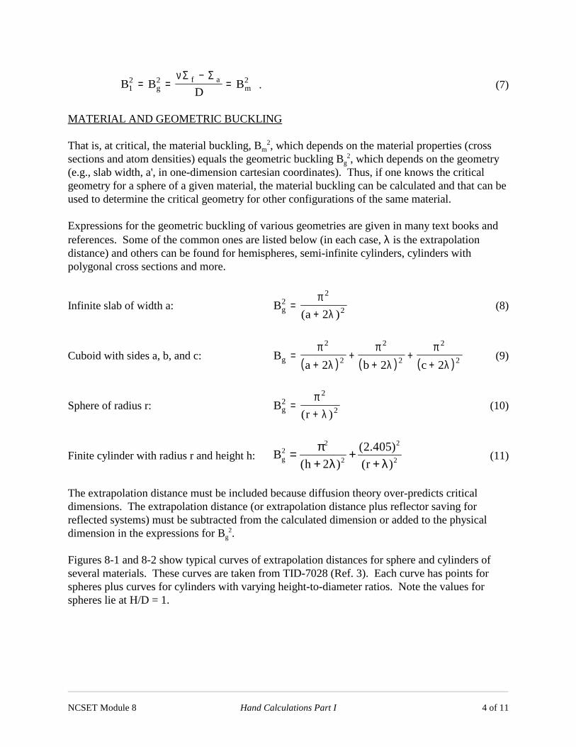
Expressions for the geometric buckling of various geometries are given in many text books andreferences. Some of the common ones are listed below (in each case, λ is the extrapolationdistance) and others can be found for hemispheres, semi-infinite cylinders, cylinders withpolygonal cross sections and more.
Infinite slab of width a: (8)Bag
22
22=
+π
λ( )
Cuboid with sides a, b, and c: (9)( ) ( ) ( )
Ba b c
g =+
++
++
πλ
πλ
πλ
2
2
2
2
2
22 2 2
Sphere of radius r: (10)Brg
22
2=+π
λ( )
Finite cylinder with radius r and height h: (11)2 2
2g 2 2
(2.405)B
(h 2 ) (r )
π= ++ λ + λ
The extrapolation distance must be included because diffusion theory over-predicts criticaldimensions. The extrapolation distance (or extrapolation distance plus reflector saving forreflected systems) must be subtracted from the calculated dimension or added to the physicaldimension in the expressions for Bg
2.
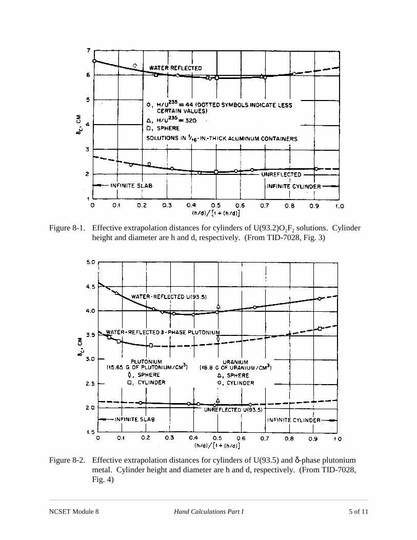
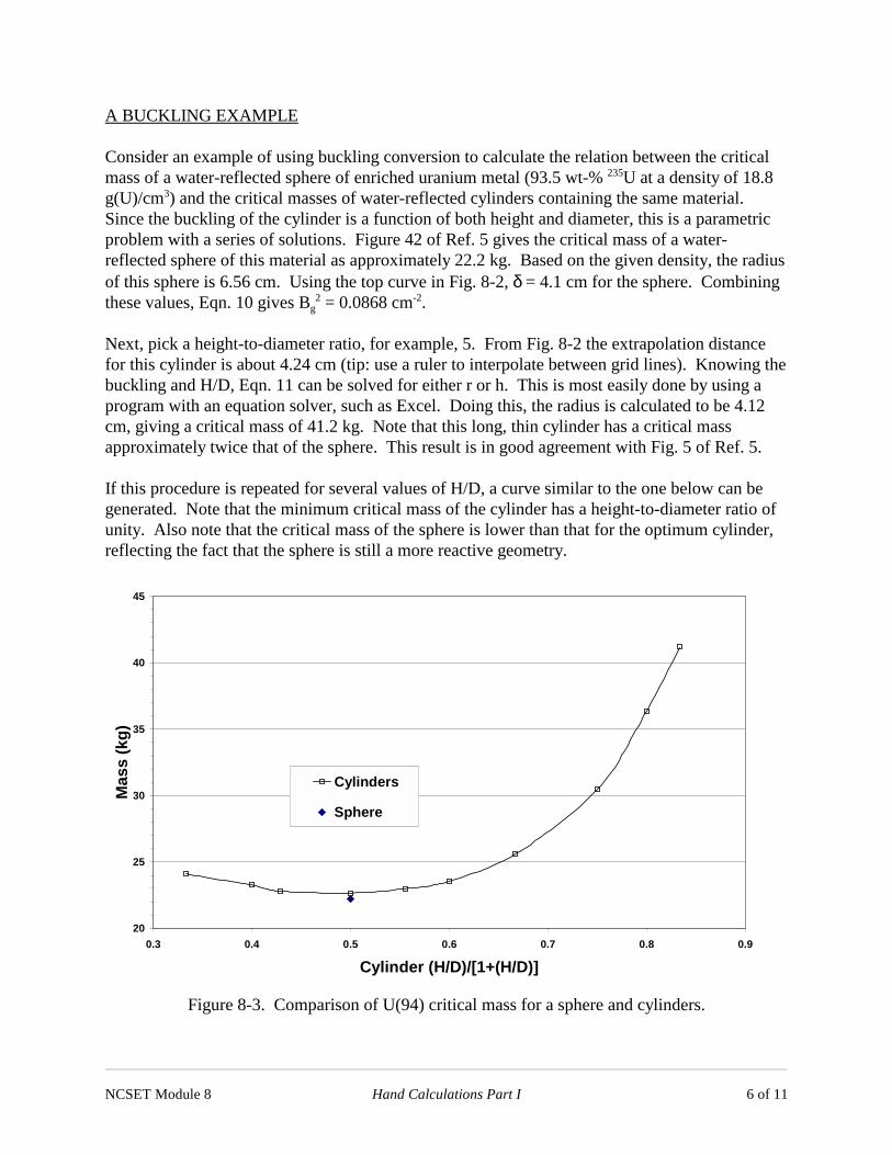
Figures 8-1 and 8-2 show typical curves of extrapolation distances for sphere and cylinders ofseveral materials. These curves are taken from TID-7028 (Ref. 3). Each curve has points forspheres plus curves for cylinders with varying height-to-diameter ratios. Note the values forspheres lie at H/D = 1.
NCSET Module 8 Hand Calculations Part I 5 of 11
Figure 8-1. Effective extrapolation distances for cylinders of U(93.2)O2F2 solutions. Cylinderheight and diameter are h and d, respectively. (From TID-7028, Fig. 3)
Figure 8-2. Effective extrapolation distances for cylinders of U(93.5) and δ-phase plutoniummetal. Cylinder height and diameter are h and d, respectively. (From TID-7028,Fig. 4)
NCSET Module 8 Hand Calculations Part I 6 of 11
20
25
30
35
40
45
0.3 0.4 0.5 0.6 0.7 0.8 0.9
Cylinder (H/D)/[1+(H/D)]
Mas
s(k
g)
Cylinders
Sphere
A BUCKLING EXAMPLE
Consider an example of using buckling conversion to calculate the relation between the criticalmass of a water-reflected sphere of enriched uranium metal (93.5 wt-% 235U at a density of 18.8g(U)/cm3) and the critical masses of water-reflected cylinders containing the same material.Since the buckling of the cylinder is a function of both height and diameter, this is a parametricproblem with a series of solutions. Figure 42 of Ref. 5 gives the critical mass of a water-reflected sphere of this material as approximately 22.2 kg. Based on the given density, the radiusof this sphere is 6.56 cm. Using the top curve in Fig. 8-2, δ = 4.1 cm for the sphere. Combiningthese values, Eqn. 10 gives Bg
2 = 0.0868 cm-2.
Next, pick a height-to-diameter ratio, for example, 5. From Fig. 8-2 the extrapolation distancefor this cylinder is about 4.24 cm (tip: use a ruler to interpolate between grid lines). Knowing thebuckling and H/D, Eqn. 11 can be solved for either r or h. This is most easily done by using aprogram with an equation solver, such as Excel. Doing this, the radius is calculated to be 4.12cm, giving a critical mass of 41.2 kg. Note that this long, thin cylinder has a critical massapproximately twice that of the sphere. This result is in good agreement with Fig. 5 of Ref. 5.
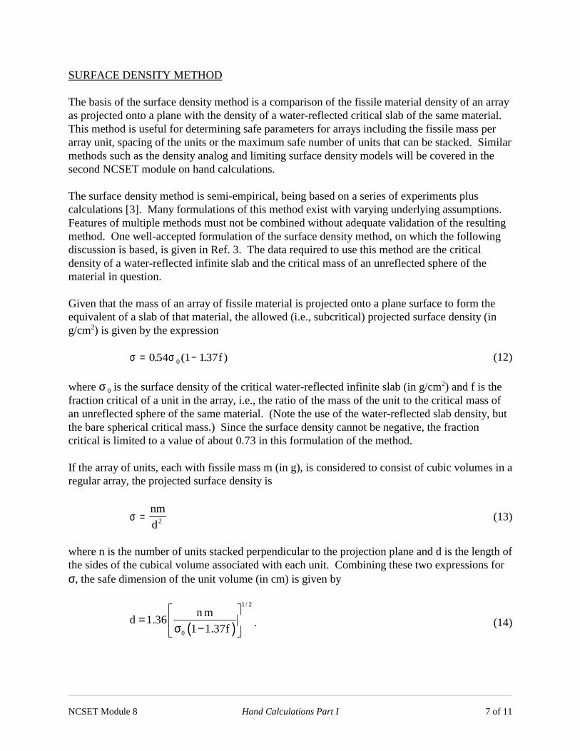
If this procedure is repeated for several values of H/D, a curve similar to the one below can begenerated. Note that the minimum critical mass of the cylinder has a height-to-diameter ratio ofunity. Also note that the critical mass of the sphere is lower than that for the optimum cylinder,reflecting the fact that the sphere is still a more reactive geometry.
Figure 8-3. Comparison of U(94) critical mass for a sphere and cylinders.
NCSET Module 8 Hand Calculations Part I 7 of 11
SURFACE DENSITY METHOD
The basis of the surface density method is a comparison of the fissile material density of an arrayas projected onto a plane with the density of a water-reflected critical slab of the same material.This method is useful for determining safe parameters for arrays including the fissile mass perarray unit, spacing of the units or the maximum safe number of units that can be stacked. Similarmethods such as the density analog and limiting surface density models will be covered in thesecond NCSET module on hand calculations.
The surface density method is semi-empirical, being based on a series of experiments pluscalculations [3]. Many formulations of this method exist with varying underlying assumptions.Features of multiple methods must not be combined without adequate validation of the resultingmethod. One well-accepted formulation of the surface density method, on which the followingdiscussion is based, is given in Ref. 3. The data required to use this method are the criticaldensity of a water-reflected infinite slab and the critical mass of an unreflected sphere of thematerial in question.
Given that the mass of an array of fissile material is projected onto a plane surface to form theequivalent of a slab of that material, the allowed (i.e., subcritical) projected surface density (ing/cm2) is given by the expression
(12)σ σ= −054 1 1370. ( . )f
where σ 0 is the surface density of the critical water-reflected infinite slab (in g/cm2) and f is thefraction critical of a unit in the array, i.e., the ratio of the mass of the unit to the critical mass ofan unreflected sphere of the same material. (Note the use of the water-reflected slab density, butthe bare spherical critical mass.) Since the surface density cannot be negative, the fractioncritical is limited to a value of about 0.73 in this formulation of the method.
If the array of units, each with fissile mass m (in g), is considered to consist of cubic volumes in aregular array, the projected surface density is
(13)σ =nm
d2
where n is the number of units stacked perpendicular to the projection plane and d is the length ofthe sides of the cubical volume associated with each unit. Combining these two expressions forσ, the safe dimension of the unit volume (in cm) is given by
. (14)( )
1/ 2
0
n md 1.36
1 1.37f
= σ −
NCSET Module 8 Hand Calculations Part I 8 of 11
In the absence of critical data, subcritical values from the figures in standard references, such asRef. 3, may be used to give conservative results. According to Ref. 3, these equations are"applicable to infinite planar arrays reflected by water at least 155 mm thick or its nuclearequivalent." The reflector can be "no closer to units in the array than the boundaries of the cellsassociated with the units." This method can be used for arrays of bare metal, dry materials orsolutions. The key is to use the data corresponding to the material or mixture in the arrayelements.
A SURFACE DENSITY EXAMPLE
The surface density method can often provide a quick, conservative answer about the safety of anarray. Consider a waste management organization that wants to store waste materials thatcontain 93 wt-% enriched UO2 mixed with various plastics, papers, etc. Their plan is to usecubical steel bins, 4-ft on edge, and stack them three-high. The proposed 235U mass limit is 325 gper bin. Is this a safe configuration?
The data needed to answer the question are the mass of a bare critical sphere of UO2 and thecritical thickness of a water-reflected slab of the same material. Since no restrictions were put onthe amount of moderating materials that could be mixed with the uranium, the worst case oroptimal moderation must be assumed. From Fig. 2.1 of Ref. 3 (or from Module 5), thesubcritical limit for a spherical mass of 235U in an aqueous UO2 solution or as a metal-watermixture is about 620 g, with a 25-mm thick reflector at a uranium concentration of about 0.044kg(U)/L. This provides a conservative value for an unreflected critical sphere. From Fig. 2.4 ofRef. 3, the subcritical thickness limit for a reflected infinite slab of 235UO2 at the same uraniumconcentration is about 96 mm.
Using the spherical mass and the proposed mass limit, the fraction critical is f = 0.524. Theallowed surface density is the product of the slab thickness and the uranium density, σ 0 = 0.422g/cm2. Putting these values into Eqn. 12, the limiting array surface density is 0.064 g/cm2. Next,solve Eqn. 13 for n to get n = 2.94. So the answer to the question about a stacking these binsthree-high is that it is probably safe, but might require a little less conservative analysis.Subcritical limits were used for both the sphere and the slab, the value for the sphere was actuallyfor a thin reflector, and no credit was taken for the enrichment of the material. Reducing theconservatism in these factors would probably give a value of n greater than three.
SUMMARY
This module has presented two simple hand calculation methods, buckling conversion andsurface density. Although largely displaced by the availability of today's fast computers, bothmethods are still used for quick, generally conservative estimates of the criticality safety of bothsingle fissile units and arrays.
NCSET Module 8 Hand Calculations Part I 9 of 11
PROBLEMS
1. A glove box used to machine samples of uranium (94 wt-% 235U) has a small rectangularsump, 8 in. x 8 in. x 8 in. deep, in one corner to collect water from wet grinding operations. Isthis sump geometrically safe? Assume the extrapolation distance for a cuboid is the same as thatfor a cylinder.
2. Table 29 of LA-10860-MS gives the critical mass of a bare sphere of U(94) with a density of18.74 g/cm3 as 49.12 kg. Calculate the radius and geometric buckling of the critical sphere.Calculate the mass and radius of a cylinder of U(94) with H/D = 1 having the same buckling.
3. A facility would like to store units of 5 kg of U(70)O2 with H:U = 12 in stacks two-high.Calculate the limiting surface density and the recommended array spacing.
NCSET Module 8 Hand Calculations Part I 10 of 11
PROBLEM SOLUTIONS
1. From Fig. 7 of LA-10860-MS, the extrapolation distance for unreflected U(94) cylinders isnearly constant at 2 cm. Using the given assumption that the extrapolation distance is the samefor a cuboid, the buckling of the sump is (from Eqn. 9)
( )2
2 2sump 2
2
B 3 cm20.32 2 2
0.050cm
−
−
π= ∗+ ∗
=
From Fig. 6 of LA-10860-MS, the ratio of the extrapolation distance for a sphere to that for acylinder is nearly one. From Eqn. 10, the radius of an equivalent sphere is then
( )2
2 2sphere 2B 0.050 cm
r−π= =
+ λ
Solving this equation, r = 12.05 cm and V = 11.6 L. Figure 2.2 of TID-7016 Rev. 2 shows thatthe minimum critical volume for 235U can be much less than 11.6 L, so this sump is notgeometrically safe.
2. Since the volume of the sphere is simply the mass divided by the density, V = 2.62 L. Theradius can then be calculated as 8.553 cm. Figure 7 of LA-10860-MS shows that the effectiveextrapolation distance for a cylinder with H/D = 1 is about 2 cm for 94% enriched uranium.Figure 6 of the same reference shows that the ratio of the spherical extrapolation distance to thecylindrical extrapolation distance is nearly 1 for cylinders with H/D = 1. Since the ratio of thespherical to cylindrical extrapolations distances is 1, and the spherical extrapolation distance isgiven as 2 cm, Equation 10 gives
( )2
2 2g 2B 0.0886cm
8.553 2−π= =
+
With this value of the buckling, and assuming that the axial and radial extrapolation distances forthe cylinder are the same, Equation 11 can be used to find the cylinder radius by inserting thebuckling calculated above with λ = 2 cm, then solving for r = 7.65 cm. Since H/D = 1, the heightof the cylinder is 15.3 cm, the volume is 2.81 L and the mass is 52.7 kg, slightly larger than thespherical critical mass.
3. This is the sample problem given in TID-7016 Rev. 2. Using the 25-mm reflected curve fromFig. 2.1 of that reference, a conservative value for the critical mass of an unreflected sphere isapproximately 14 kg (U). (Note that this is for 235U. According to Fig. 3.4 of TID-7016 thisvalue could be increased by a factor of 1.5 for 70% enriched material.) From Fig. 2.4 of TID-7016 the reflected critical slab thickness is about 34 mm (also conservative since this is a
NCSET Module 8 Hand Calculations Part I 11 of 11
subcritical limit). At H:U = 12, the density of uranium in the solution is about 2.1 g(U)/cm3. Thesurface density of the critical slab is then
30
2
2.1g(U) / cm 3.4cm
7.14g(U) / cm
σ = ∗
=
The fraction critical, not accounting for the enrichment, is f = 5/14 = 0.357. Then using Eqn. 12,the allowed surface density is
( )2
0.54 7.14 1 1.37 0.357
1.97 g(U) / cm
σ = ∗ ∗ − ∗
=
Eqn. 14 then gives, for the two-tier array,
d = 71.2 cm .
If the mass factor for the U(70) sphere is used, the fraction critical becomes 0.238, the surfacedensity becomes 2.6 g(U)/cm2 and the allowed spacing is 62.0 cm.