module 3.0: nuclear theory · module 3.0: nuclear theory introduction welcome to module 3.0 of the...
TRANSCRIPT

MODULE 3.0: NUCLEAR THEORY
Introduction Welcome to Module 3.0 of the Nuclear Criticality Safety Directed Self-Study Course! This is the third of five modules available in thisdirected self-study course. The purpose of this module is to assist youin describing the fission process and basic nuclear theory concepts.
This directed self-study module is designed to assist you inaccomplishing the learning objectives listed at the beginning of themodule. There are four sections in this module. The module hasself-check questions and activities to help you assess yourunderstanding of the concepts presented in the module. Please notethere are also optional activities that are not required for completionof this module. These are noted at the beginning of the activity
Before You Begin It is recommended that you have access to the following material:
� Trainee Guide
Complete the following prerequisite:
� There are no prerequisites to this module.
How to Completethis Module 1. Review the learning objectives.
2. Read each section within the module in sequential order.3. Complete the self-check questions and activities within this
module.4. Check off the tracking form as you complete the self-check
questions and/or activities within the module.5. Contact your administrator as prompted for a progress review
meeting.6. Contact your administrator as prompted for any additional
materials and/or specific assignments.7. Complete all assignments related to this module. 8. Ensure that you and your administrator have dated and initialed
your progress on the tracking form.

Module 3.0: Nuclear Theory
USNRC Technical Training Center 0905 (Rev 3)Nuclear Criticality Safety Directed Self-Studyi
9. Go to the next assigned module.
TABLE OF CONTENTS
Learning Objectives . . . . . . . . . . . . . . . . . . . . . . . . . . . . . . . . . . . . . . . . . . . . . . . . . . . . . 3-1Definitions . . . . . . . . . . . . . . . . . . . . . . . . . . . . . . . . . . . . . . . . . . . . . . . . . . . . . . . . . . . . . 3-2
Self-Check Questions 3-1 . . . . . . . . . . . . . . . . . . . . . . . . . . . . . . . . . . . . . . . . . . . . . . . 3-4Nuclear Reactions . . . . . . . . . . . . . . . . . . . . . . . . . . . . . . . . . . . . . . . . . . . . . . . . . . . . . . . 3-5
Fission Process . . . . . . . . . . . . . . . . . . . . . . . . . . . . . . . . . . . . . . . . . . . . . . . . . . . . . . . 3-5Nuclear Reactions . . . . . . . . . . . . . . . . . . . . . . . . . . . . . . . . . . . . . . . . . . . . . . . . . . . . . 3-5Neutron Reactions . . . . . . . . . . . . . . . . . . . . . . . . . . . . . . . . . . . . . . . . . . . . . . . . . . . . 3-6Nuclear Fission Reaction . . . . . . . . . . . . . . . . . . . . . . . . . . . . . . . . . . . . . . . . . . . . . . . . 3-6Fissioning Materials . . . . . . . . . . . . . . . . . . . . . . . . . . . . . . . . . . . . . . . . . . . . . . . . . . . . 3-7What Fissionable Material Is Present at NRC Licensee Facilities? . . . . . . . . . . . . . . . . 3-8Fission Energy Release . . . . . . . . . . . . . . . . . . . . . . . . . . . . . . . . . . . . . . . . . . . . . . . . 3-8Overall Heat Energy Equation . . . . . . . . . . . . . . . . . . . . . . . . . . . . . . . . . . . . . . . . . . . . 3-8What Are the Consequences of Fission Energy Release to a Criticality Accident? . . . . 3-8Fission Fragments . . . . . . . . . . . . . . . . . . . . . . . . . . . . . . . . . . . . . . . . . . . . . . . . . . . . . 3-9Consequences of Fission Products . . . . . . . . . . . . . . . . . . . . . . . . . . . . . . . . . . . . . . . . 3-9Fission Neutrons . . . . . . . . . . . . . . . . . . . . . . . . . . . . . . . . . . . . . . . . . . . . . . . . . . . . . 3-10Neutron Characteristics . . . . . . . . . . . . . . . . . . . . . . . . . . . . . . . . . . . . . . . . . . . . . . . . 3-10Neutron Energy Considerations . . . . . . . . . . . . . . . . . . . . . . . . . . . . . . . . . . . . . . . . . 3-10Moderation of Neutrons . . . . . . . . . . . . . . . . . . . . . . . . . . . . . . . . . . . . . . . . . . . . . . . . 3-10Moderators . . . . . . . . . . . . . . . . . . . . . . . . . . . . . . . . . . . . . . . . . . . . . . . . . . . . . . . . . 3-10Effects of Moderators and Non-Moderators on Critical Systems . . . . . . . . . . . . . . . . . 3-11Neutron Balance Equation . . . . . . . . . . . . . . . . . . . . . . . . . . . . . . . . . . . . . . . . . . . . . 3-11
Cross Section . . . . . . . . . . . . . . . . . . . . . . . . . . . . . . . . . . . . . . . . . . . . . . . . . . . . . . . . . 3-12Energy Dependence of Microscopic Cross Sections . . . . . . . . . . . . . . . . . . . . . . . . . . 3-12Energy-Dependent Cross Sections for Uranium . . . . . . . . . . . . . . . . . . . . . . . . . . . . . 3-13
Infinite System . . . . . . . . . . . . . . . . . . . . . . . . . . . . . . . . . . . . . . . . . . . . . . . . . . . . . . . . 3-14Infinite Multiplication Factor . . . . . . . . . . . . . . . . . . . . . . . . . . . . . . . . . . . . . . . . . . . . . 3-14Four-Factor Formula . . . . . . . . . . . . . . . . . . . . . . . . . . . . . . . . . . . . . . . . . . . . . . . . . . 3-15Heterogeneous Systems . . . . . . . . . . . . . . . . . . . . . . . . . . . . . . . . . . . . . . . . . . . . . . . 3-16
Finite System . . . . . . . . . . . . . . . . . . . . . . . . . . . . . . . . . . . . . . . . . . . . . . . . . . . . . . . . . . 3-17Neutron Balance . . . . . . . . . . . . . . . . . . . . . . . . . . . . . . . . . . . . . . . . . . . . . . . . . . . . . 3-17Reactivity . . . . . . . . . . . . . . . . . . . . . . . . . . . . . . . . . . . . . . . . . . . . . . . . . . . . . . . . . . . 3-18Nuclear Criticality Safety Practice . . . . . . . . . . . . . . . . . . . . . . . . . . . . . . . . . . . . . . . . 3-18Neutron-Balance Terms . . . . . . . . . . . . . . . . . . . . . . . . . . . . . . . . . . . . . . . . . . . . . . . 3-18Activity 1 - Neutron Balance . . . . . . . . . . . . . . . . . . . . . . . . . . . . . . . . . . . . . . . . . . . . 3-19Illustrative Example . . . . . . . . . . . . . . . . . . . . . . . . . . . . . . . . . . . . . . . . . . . . . . . . . . . 3-20Consequences/Impacts . . . . . . . . . . . . . . . . . . . . . . . . . . . . . . . . . . . . . . . . . . . . . . . . 3-21Activity 2 - Operating Limit Values . . . . . . . . . . . . . . . . . . . . . . . . . . . . . . . . . . . . . . . . 3-22Self-Check Questions 3-2 . . . . . . . . . . . . . . . . . . . . . . . . . . . . . . . . . . . . . . . . . . . . . . 3-23
Computational Methods . . . . . . . . . . . . . . . . . . . . . . . . . . . . . . . . . . . . . . . . . . . . . . . . . 3-28Introduction . . . . . . . . . . . . . . . . . . . . . . . . . . . . . . . . . . . . . . . . . . . . . . . . . . . . . . . . . 3-28Diffusion Theory . . . . . . . . . . . . . . . . . . . . . . . . . . . . . . . . . . . . . . . . . . . . . . . . . . . . . 3-28Calculations Used with Single Units . . . . . . . . . . . . . . . . . . . . . . . . . . . . . . . . . . . . . . 3-29Geometric Buckling . . . . . . . . . . . . . . . . . . . . . . . . . . . . . . . . . . . . . . . . . . . . . . . . . . . 3-29Buckling Conversion . . . . . . . . . . . . . . . . . . . . . . . . . . . . . . . . . . . . . . . . . . . . . . . . . . 3-30

Module 3.0: Nuclear Theory
USNRC Technical Training Center 0905 (Rev 3)Nuclear Criticality Safety Directed Self-Studyii
Example . . . . . . . . . . . . . . . . . . . . . . . . . . . . . . . . . . . . . . . . . . . . . . . . . . . . . . . . . . . 3-32Key Points . . . . . . . . . . . . . . . . . . . . . . . . . . . . . . . . . . . . . . . . . . . . . . . . . . . . . . . . . . 3-33Activity 3 - Buckling Conversion . . . . . . . . . . . . . . . . . . . . . . . . . . . . . . . . . . . . . . . . . 3-34Six-Factor Formula . . . . . . . . . . . . . . . . . . . . . . . . . . . . . . . . . . . . . . . . . . . . . . . . . . . 3-36Age-Diffusion/ Migration-Area Approximation . . . . . . . . . . . . . . . . . . . . . . . . . . . . . . . 3-37Activity 4 - Migration-Area Approximation . . . . . . . . . . . . . . . . . . . . . . . . . . . . . . . . . . 3-38Fraction Critical Method . . . . . . . . . . . . . . . . . . . . . . . . . . . . . . . . . . . . . . . . . . . . . . . 3-40Activity 5 - Fraction Critical . . . . . . . . . . . . . . . . . . . . . . . . . . . . . . . . . . . . . . . . . . . . . 3-41Calculations Used with Arrays . . . . . . . . . . . . . . . . . . . . . . . . . . . . . . . . . . . . . . . . . . . 3-43Surface Density Method . . . . . . . . . . . . . . . . . . . . . . . . . . . . . . . . . . . . . . . . . . . . . . . 3-43Key Points . . . . . . . . . . . . . . . . . . . . . . . . . . . . . . . . . . . . . . . . . . . . . . . . . . . . . . . . . . 3-45Activity 6 - Surface Density . . . . . . . . . . . . . . . . . . . . . . . . . . . . . . . . . . . . . . . . . . . . . 3-46Solid Angle Method . . . . . . . . . . . . . . . . . . . . . . . . . . . . . . . . . . . . . . . . . . . . . . . . . . . 3-48Example . . . . . . . . . . . . . . . . . . . . . . . . . . . . . . . . . . . . . . . . . . . . . . . . . . . . . . . . . . . 3-50Key Points . . . . . . . . . . . . . . . . . . . . . . . . . . . . . . . . . . . . . . . . . . . . . . . . . . . . . . . . . . 3-50Activity 7 - Solid Angle . . . . . . . . . . . . . . . . . . . . . . . . . . . . . . . . . . . . . . . . . . . . . . . . 3-51Activity 8 - Solid Angle . . . . . . . . . . . . . . . . . . . . . . . . . . . . . . . . . . . . . . . . . . . . . . . . 3-53Self-Check Questions 3-3 . . . . . . . . . . . . . . . . . . . . . . . . . . . . . . . . . . . . . . . . . . . . . . 3-55
Computer Codes . . . . . . . . . . . . . . . . . . . . . . . . . . . . . . . . . . . . . . . . . . . . . . . . . . . . . . . 3-57Introduction . . . . . . . . . . . . . . . . . . . . . . . . . . . . . . . . . . . . . . . . . . . . . . . . . . . . . . . . . 3-57Validation, Bias, and Bias Uncertainty . . . . . . . . . . . . . . . . . . . . . . . . . . . . . . . . . . . . . 3-57Computational Tools . . . . . . . . . . . . . . . . . . . . . . . . . . . . . . . . . . . . . . . . . . . . . . . . . . 3-58Finite Difference Methods . . . . . . . . . . . . . . . . . . . . . . . . . . . . . . . . . . . . . . . . . . . . . . . 3-58Monte Carlo Methods . . . . . . . . . . . . . . . . . . . . . . . . . . . . . . . . . . . . . . . . . . . . . . . . . . 3-59KENO . . . . . . . . . . . . . . . . . . . . . . . . . . . . . . . . . . . . . . . . . . . . . . . . . . . . . . . . . . . . . . 3-61MCNP . . . . . . . . . . . . . . . . . . . . . . . . . . . . . . . . . . . . . . . . . . . . . . . . . . . . . . . . . . . . . . 3-62MONK . . . . . . . . . . . . . . . . . . . . . . . . . . . . . . . . . . . . . . . . . . . . . . . . . . . . . . . . . . . . . . 3-63Self-Check Questions 3-4 . . . . . . . . . . . . . . . . . . . . . . . . . . . . . . . . . . . . . . . . . . . . . 3-65
Progress Review Meeting Form . . . . . . . . . . . . . . . . . . . . . . . . . . . . . . . . . . . . . . . . . . . 3-67Module Summary . . . . . . . . . . . . . . . . . . . . . . . . . . . . . . . . . . . . . . . . . . . . . . . . . . . . . . 3-70
LIST OF TABLES
Table 3-1. Advantages and Disadvantages of a Fission Reaction . . . . . . . . . . . . . . . . . . . 3-7Table 3-2. Categories of Materials That Fission . . . . . . . . . . . . . . . . . . . . . . . . . . . . . . . . . 3-7Table 3-3. Fission Products . . . . . . . . . . . . . . . . . . . . . . . . . . . . . . . . . . . . . . . . . . . . . . . . 3-8Table 3-4. Neutron Balance . . . . . . . . . . . . . . . . . . . . . . . . . . . . . . . . . . . . . . . . . . . . . . . 3-12Table 3-5. Four Terms of the Infinite Multiplication Factor . . . . . . . . . . . . . . . . . . . . . . . . 3-15Table 3-6. keff and � as Relates to Criticality State . . . . . . . . . . . . . . . . . . . . . . . . . . . . . . 3-18Table 3-7. Geometric Buckling Configuration . . . . . . . . . . . . . . . . . . . . . . . . . . . . . . . . . . 3-30Table 3-8. Adjusted Geometric Buckling Configuration . . . . . . . . . . . . . . . . . . . . . . . . . . 3-31
LIST OF FIGURES
Figure 3-1. Nuclear Reactions . . . . . . . . . . . . . . . . . . . . . . . . . . . . . . . . . . . . . . . . . . . . . 3-6Figure 3-2. Fission Reaction of Uranium-235 . . . . . . . . . . . . . . . . . . . . . . . . . . . . . . . . . . 3-7Figure 3-3. Double-humped (Bi-Model) Spectrum . . . . . . . . . . . . . . . . . . . . . . . . . . . . . . 3-9Figure 3-4. 235U Fission Cross Section . . . . . . . . . . . . . . . . . . . . . . . . . . . . . . . . . . . . . . 3-14
Module 3.0: Nuclear Theory
USNRC Technical Training Center 0905 (Rev 3)Nuclear Criticality Safety Directed Self-Studyiii
Figure 3-5. Critical Mass of LEU as a Function of Uranium Enrichment . . . . . . . . . . . . . 3-17Figure 3-6. Critical Mass Versus Concentration Data for 235U . . . . . . . . . . . . . . . . . . . . 3-20Figure 3-7. Calculations for Critical Radius . . . . . . . . . . . . . . . . . . . . . . . . . . . . . . . . . . 3-32Figure 3-8. Migration Area Approximation Formula . . . . . . . . . . . . . . . . . . . . . . . . . . . . 3-37Figure 3-9. Age-Diffusion Formula . . . . . . . . . . . . . . . . . . . . . . . . . . . . . . . . . . . . . . . . . 3-37Figure 3-10. Surface Density Method . . . . . . . . . . . . . . . . . . . . . . . . . . . . . . . . . . . . . . . . 3-44Figure 3-11. Example of Calculation Using the Surface Density Method . . . . . . . . . . . . . 3-44Figure 3-12. Solid Angle Method . . . . . . . . . . . . . . . . . . . . . . . . . . . . . . . . . . . . . . . . . . . 3-48Figure 3-13. Solid Angle Method Formula . . . . . . . . . . . . . . . . . . . . . . . . . . . . . . . . . . . . 3-49Figure 3-14. Point-to-Cylinder . . . . . . . . . . . . . . . . . . . . . . . . . . . . . . . . . . . . . . . . . . . . . 3-49Figure 3-15. Monte Carlo Model KENO . . . . . . . . . . . . . . . . . . . . . . . . . . . . . . . . . . . . . . 3-60
Module 3.0: Nuclear Theory
USNRC Technical Training Center 0905 (Rev 3)Nuclear Criticality Safety Directed Self-Study3-1
Learning Objectives 3.1 Upon completion of this module, you will be able to
describe the fission process and basic nuclear theoryconcepts.
3.1.1 Define the terms:� fissile isotopes� fissile material� fissile system� fission, nuclear� fissionable isotopes
3.1.2 Describe the fission chain reaction in terms of the following:
� energy release� neutron production
- number- energy- timing (prompt and delayed)
� absorption, scattering, and leakage� radiation types and time history
3.1.3 Define keff and qualitatively state changes whenparameters are changed.
3.1.4 Identify the purpose and basic features of each of thefollowing hand calculation methods:
� buckling conversion� age-diffusion migration area approximation� fraction critical� solid angle� surface density
3.1.5 Identify the purpose and basic features of the Monte Carlocomputer code KENO.

Module 3.0: Nuclear Theory
USNRC Technical Training Center 0905 (Rev 3)Nuclear Criticality Safety Directed Self-Study3-2
Learning Objective
When you finish this section, you will be able to:
3.1.1 Define the terms:� fissile isotopes� fissile material� fissile system� fission, nuclear� fissionable isotopes
DEFINITIONS These are terms that you will need to be familiar with while reviewingthis module:
Fissile IsotopesFissile isotopes are the subset of the fissionable isotopes that willsustain a fission-chain reaction using thermal neutrons. The importantisotopes 233U, 235U, 239Pu, and 241Pu are fissile isotopes. Fissileisotopes in solution or in special mixtures can absorb thermalneutrons and sustain chain reactions with much smaller masses thanthose usually required for sustained fission; therefore, fissile isotopespose a greater risk of an accidental criticality.
Fissile MaterialA material, other than natural uranium, that is capable of sustaining aneutron chain reaction. Source: ANSI/ANS 8.7, 1975.
Fissile SystemA system containing 235U, 239Pu, or 233U nuclei and capable ofsignificant neutron multiplication.
Fission, Nuclear1. Nuclear reaction in which a neutron and nucleus interact with theresult that the nucleus splits into two or more parts. Fission reactionsof interest here release net energy and produce neutrons that canparticipate in a sustained chain reaction. 2. Disintegration of anucleus (usually Th, U, Pu, or heavier) into two (rarely more) massesof similar order of magnitude, accompanied by a large release ofenergy and the emission of neutrons. Although some fissions takeplace spontaneously, neutron-induced fissions are designated �f, and� is the number of neutrons emitted per fission.
Fissionable IsotopeA fissionable isotope is any isotope capable of sustaining a neutron-induced fission-chain reaction, regardless of the neutron energy or

Module 3.0: Nuclear Theory
USNRC Technical Training Center 0905 (Rev 3)Nuclear Criticality Safety Directed Self-Study3-3
speed necessary to induce and sustain the reaction. For practicalnuclear criticality safety purposes, these isotopes are limited to 233U,235U, 241Am, 242mAm, 243Am, 243Cm, 244Cm, 245Cm, 247Cm, 249Cf, 251Cf,237Np, 238Pu, 239Pu, 240Pu, 241Pu, and 242Pu. Although other isotopes ofsome of the above elements would sustain fission, the quantityrequired for a self-sustaining chain reaction is so great and/or themass available is so small as to make a nuclear-criticality accidentincredible.
Module 3.0: Nuclear Theory
USNRC Technical Training Center 0905 (Rev 3)Nuclear Criticality Safety Directed Self-Study3-4
Self-Check Questions 3-1
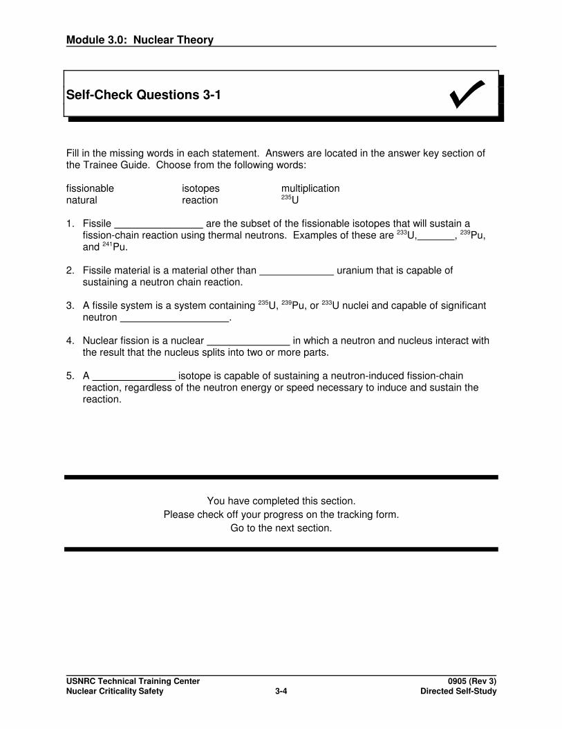
Fill in the missing words in each statement. Answers are located in the answer key section ofthe Trainee Guide. Choose from the following words:
fissionable isotopes multiplicationnatural reaction 235U
1. Fissile are the subset of the fissionable isotopes that will sustain afission-chain reaction using thermal neutrons. Examples of these are 233U, , 239Pu,and 241Pu.
2. Fissile material is a material other than uranium that is capable ofsustaining a neutron chain reaction.
3. A fissile system is a system containing 235U, 239Pu, or 233U nuclei and capable of significantneutron .
4. Nuclear fission is a nuclear in which a neutron and nucleus interact withthe result that the nucleus splits into two or more parts.
5. A isotope is capable of sustaining a neutron-induced fission-chainreaction, regardless of the neutron energy or speed necessary to induce and sustain thereaction.
You have completed this section.Please check off your progress on the tracking form.
Go to the next section.
Module 3.0: Nuclear Theory
USNRC Technical Training Center 0905 (Rev 3)Nuclear Criticality Safety Directed Self-Study3-5
Learning Objectives
When you finish this section, you will be able to:
3.1.2 Describe the fission chain reaction in terms of the following:
� energy release� neutron production
- number- energy- timing (prompt and delayed)
� absorption, scattering, and leakage� radiation types and time history
3.1.3 Define keff and qualitatively state changes when parameters are changed.
NUCLEARREACTIONS
Fission Process The fission process and its associated neutron chain reactionproduces energy, which is used by licensees in:
� Generation of electricity
� Propulsion
� Production of radioisotopes
� Research
Nuclear Reactions The physics of criticality and nuclear criticality safety depends first onidentification of nuclear reactions.
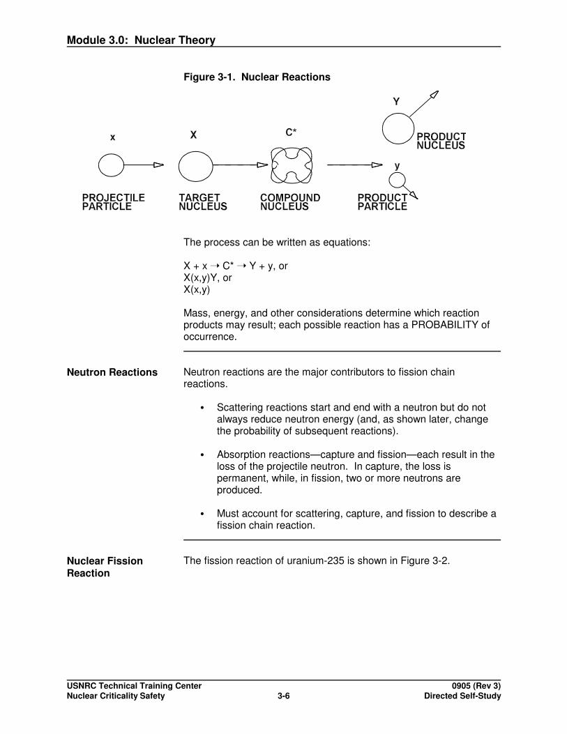
The basic mechanism for a nuclear reaction involves a PROJECTILEparticle (x) and a TARGET nucleus (X), combining to form anunstable COMPOUND NUCLEUS (C*), which decomposes into twoor more PRODUCTS (Y and y) plus excess energy in the form ofradiation. See Figure 3-1.
Module 3.0: Nuclear Theory
USNRC Technical Training Center 0905 (Rev 3)Nuclear Criticality Safety Directed Self-Study3-6
Figure 3-1. Nuclear Reactions
The process can be written as equations:
X + x � C* � Y + y, orX(x,y)Y, orX(x,y)
Mass, energy, and other considerations determine which reactionproducts may result; each possible reaction has a PROBABILITY ofoccurrence.
Neutron Reactions Neutron reactions are the major contributors to fission chainreactions.
� Scattering reactions start and end with a neutron but do notalways reduce neutron energy (and, as shown later, changethe probability of subsequent reactions).
� Absorption reactions—capture and fission—each result in theloss of the projectile neutron. In capture, the loss ispermanent, while, in fission, two or more neutrons areproduced.
� Must account for scattering, capture, and fission to describe afission chain reaction.
Nuclear FissionReaction
The fission reaction of uranium-235 is shown in Figure 3-2.

Module 3.0: Nuclear Theory
USNRC Technical Training Center 0905 (Rev 3)Nuclear Criticality Safety Directed Self-Study3-7
n
nn
n
n Neutron
FISSION
FISSION FRAGMENTS
1.6s 32.5s 2.7min. 29y 64h stable
90Br 90 Kr 90Sr 90Y 90Zr 90 Rb
γ β β ββγ βγ
γ β βγ βγ βγ βγ β 143Xe 143Cs 143Ba 143La 143Ce 143Pr 143Nd
γγ
γγ235 U
GAMMA RAYS
0.69s 1.7s 12s 14min. 33h 13.6d stable
Figure 3-2. Fission Reaction of Uranium-235
The reaction has advantages and disadvantages. See Table 3-1.
Table 3-1. Advantages and Disadvantages of a Fission Reaction
Advantages Disadvantages
Heat - Provides compact energysource Radiation - Requires shielding,
containment, and heat removalNeutrons - Allow self-sustainingchain reaction
Fissioning Materials The two basic categories of materials that fission are described in Table 3-2.
Table 3-2. Categories of Materials That Fission
Category Definition Species Result
Fissile Isotopes that can befissioned by neutrons of any energy
235U, 233U, 239Pu, 241Pu
Can sustain a fissionchain reaction
Fissionable Isotopes that can befissioned by HIGH energyneutrons (but not by lowenergy neutrons)
238U, 232Th, 240Pu Can participate in afission chain reaction

Module 3.0: Nuclear Theory
USNRC Technical Training Center 0905 (Rev 3)Nuclear Criticality Safety Directed Self-Study3-8
What FissionableMaterial Is Presentat NRC LicenseeFacilities?
� The dominant fissionable material in NRC licensee fuel cyclefacilities is uranium (fissile 235U and non-fissile 238U).
� Plutonium is present at reactor sites and storage facilities (e.g.,GE-Morris) in spent fuel and will be a concern for wastemanagement.
�233U is present only in research-related activities (e.g., high-temperature gas-cooled reactor programs).
Fission EnergyRelease
Fission energy release is divided among the various fission productsas shown in Table 3-3.
Table 3-3. Fission Products
Fission Products MeV% of Energy
Release
Fission Fragments (usually two) 168 84
Neutrons 5 2.5
Prompt Gamma Rays 7 3.5
DelayedRadiation
Beta Particles 8 4
Gamma Rays 7 3.5
Radiative Capture Gammas 5 2.5
Total 200 100
Overall Heat EnergyEquation
Overall heat energy from fission is produced at a rate given by thefollowing equation:
3.1 x 10¹⁰ fissions � 1 watt-s
(This expression can be used to convert total fissions or fission rate inan excursion to an equivalent energy production.)
What Are theConsequences ofFission EnergyRelease to aCriticality Accident?
Criticality accidents have:
� Large radiation sources at the time of fission
� Delayed beta and gamma radiation, which gives rise to long-term radiation sources

Module 3.0: Nuclear Theory
USNRC Technical Training Center 0905 (Rev 3)Nuclear Criticality Safety Directed Self-Study3-9
Fission Fragments When fissionable nuclei split into two FISSION FRAGMENTS, thefragments are seldom of equal mass (e.g., only 0.01% in 235U). Instead, there is a range of products, as shown in the "double-humped" (bi-modal) spectrum. See Figure 3-3. (Here for 235U,species in the ranges A = 90 - 100 and A = 135 - 145 may each haveoccurred in as many as ~7% of fissions. Overall, there are >200species of fission products.
Figure 3-3. Double-humped (Bi-Modal) Spectrum
Consequences ofFission Products
Consequences of fission products:
� Some fission products are gaseous (iodine) and others arevolatile (strontium and cesium).
� Gaseous and volatile fission products spread readily ascontamination, following an accident.
� Radioactive wastes from an accident or from spent fuel aremulti-species and, therefore, complex.

Module 3.0: Nuclear Theory
USNRC Technical Training Center 0905 (Rev 3)Nuclear Criticality Safety Directed Self-Study3-10
Fission Neutrons Neutrons emitted from fission are characterized by:
� Number � that generally is greater than two (~2.5 for 235U)
� Timing that is either:
PROMPT - at time of fission (>99%) orDELAYED - following fission fragment decay
(0.2%-0.7%;~0.1 seconds to 1 minute afterfission)
� Energy spectrum (E):
Most probable energy 0.7 MeVAverage energy 2.0 MeVBasic energy range 0.1 MeV to 10 MeV
NeutronCharacteristics
Neutron characteristics:
� Sufficient neutrons are needed to support a self-sustainingchain reaction.
� Presence of delayed neutrons allows for control of a neutronchain reaction in reactors and the possibility of a "delayedcritical" accident scenario (e.g., as described later and as mayaffect the design of criticality alarm systems).
Neutron EnergyConsiderations
Because neutrons are born fast (>0.1 MeV) but are best at causingfission when moderated to thermal energies (on the order of less than1 eV), moderating materials like water are important to both reactordesign and nuclear criticality safety.
Moderation ofNeutrons
Moderation of neutrons occurs when neutrons undergo scatteringreactions. Elastic scattering of neutrons with low-Z materials resultsin relatively large energy changes per collision. (For a neutron andhydrogen atom, the analogy is a collision of two billiard balls). Withhigh-Z materials, small energy changes per collision occur (analogousto a billiard ball striking a bowling ball).
Moderators Moderators include:
� WATER, which, due to its hydrogen content, can be veryefficient in a relatively small volume; however, it also hassignificant absorption.
� DEUTERIUM (as in heavy water), BERYLLIUM, and
Module 3.0: Nuclear Theory
USNRC Technical Training Center 0905 (Rev 3)Nuclear Criticality Safety Directed Self-Study3-11
GRAPHITE are less efficient moderators (in terms of energychange per collision) and, thus, require successively largervolumes; however, each has much lower neutron absorptionthan water.
� Any of the above moderators, in the proper quantity anddistribution, can reduce substantially the minimum amount offissile material required to sustain a chain reaction.
� Elements in the range of 11<Z<83 are considered "NON-MODERATORS," which separate fissile nuclides, thereby,reducing the probability of fission.
� Heavy metals, including the fissionable materials, cause verysmall energy change per collision from elastic scattering.
� Inelastic scattering from some nuclides also contributes toneutron energy loss but generally in a manner of consequenceonly for detailed calculations.
Effects ofModerators andNon-Moderators onCritical Systems
Effects of moderators and non-moderators on critical systems:
� Hydrogen, deuterium, beryllium, and carbon are moderatingmaterials that, when mixed, can reduce substantially the fissilematerial mass required to support a neutron chain reaction. Under usual conditions, only hydrogen (e.g., in water, plastic,or oil) or carbon (e.g., in organic liquids or other materials)would be expected to provide a source of accidentalmoderation.
� Accidental mixing of a non-moderator (e.g., aluminum powderor silicon from sand) can be expected to separate the fissilenuclides, thereby reducing the probability of fission.
� Metallic and other solid forms of fissile material do not exhibitsignificant moderation effects.
Neutron BalanceEquation
A neutron balance equation for the fission chain reaction is as follows:
Rate of Increase Rate of Rate of Rate ofin Number of = Production — Absorption — LeakageNeutrons of Neutrons of Neutrons of Neutrons
Accumulation = Production — Absorption — Leakage
See Table 3-4.

Module 3.0: Nuclear Theory
USNRC Technical Training Center 0905 (Rev 3)Nuclear Criticality Safety Directed Self-Study3-12
Table 3-4. Neutron Balance
Ifaccumulationis:
Thesystem is:
The neutronpopulationsis:
The systembehavior is:
=0 Critical Steady State Static
>0 Supercritical
Increasing Kinetic/Dynamic
<0 Subcritical Decreasing Kinetic/Dynamic
CROSS SECTION The concept of a CROSS SECTION was developed from theperception that:
Interaction Probability = n � dx
where n = density of atoms (at/cm3)
� = cross-sectional area [of the target nucleus] (cm2/at)
dx = distance traveled by neutron (cm)
However, with the determination that the interaction probability for agiven material changed substantially with neutron energy, andbecause it was not easy to view the nucleus as changing size, thefollowing term was defined without specific connection to physicaldimensions:
The unit of measurement was selected as:
1 barn [b] = 10-24 cm2
The name was derived from the intended-to-be-humorousobservation that such a target was "as big as the side of a barn."
Energy Dependenceof MicroscopicCross Sections
ENERGY DEPENDENCE of microscopic cross sections is verycomplex. A few of the key features include:
POTENTIAL SCATTERING cross section is approximately the size ofnucleus.

Module 3.0: Nuclear Theory
USNRC Technical Training Center 0905 (Rev 3)Nuclear Criticality Safety Directed Self-Study3-13
Absorption cross section over a wide energy range varies roughly as"ONE-OVER-v," which in equation form is:
�a(E) = �0 (v0 / v) = �0 (E0 / E)1/2
Here the interaction probability is generally proportional to the "timespent near the nucleus' force field."
In the RESONANCE region, specific "energy levels" in the nucleusgive rise to extremely high cross sections at rather precise neutronenergies. Absorption, scattering, and fission cross sections canexhibit this trait.
Energy-DependentCross Sections forUranium
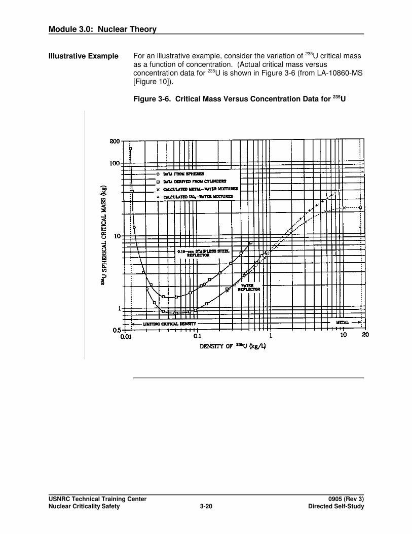
The energy-dependent cross-section plots in Figure 3-4 show that:
�235U has thermal and fast fission and is therefore fissile
�238U has fast fission only and is therefore fissionable, but non-fissile
�235U has a fission cross section several orders of magnitudegreater for thermal than for fast neutrons; thus, neutronmoderation can considerably increase the reaction probability.

Module 3.0: Nuclear Theory
USNRC Technical Training Center 0905 (Rev 3)Nuclear Criticality Safety Directed Self-Study3-14
10-4 10-3 10-2 10-1 1 102 103 104 105 106 107101
1
10
100
1000
10,000
0.1
NEUTRON ENERGY, eV
238 U
FIS
SIO
N C
RO
SS
SE
CTI
ON
, bar
nes
235U
INFINITE SYSTEM
InfiniteMultiplicationFactor
An initial look at developing a model for the fission chain reactionbegins with consideration of an infinite system. Here, by definition,there is no leakage (the term which turns out to be very difficult toquantify), so only neutron production and absorption need beconsidered.
Figure 3-4. 235U Fission Cross Section
The neutron balance for an infinite system compares production andabsorption rates with the result, based on definitions in the previoussection, that:
Production Rate � Absorption Rate
��f� �a�
It is convenient to define the INFINITE MULTIPLICATION FACTORk� as:

Module 3.0: Nuclear Theory
USNRC Technical Training Center 0905 (Rev 3)Nuclear Criticality Safety Directed Self-Study3-15
This expression represents the multiplication—the ratio of the neutronpopulation in one generation of fissions to that of the previousgeneration—for a system with no neutron leakage (or one that islarge enough that leakage can be neglected). Thus, it reflects thehighest multiplication possible for a given material composition.
The definition for k� is deceptively simple in appearance. Because ofthe complexity of reaction cross sections and the neutron flux, theparameters are essentially averaged, or "one-energy-group," valuesthat must be calculated through a complex process like energy thatwhich will be summarized later.
Four-FactorFormula
To look at neutron multiplication independent of the mathematicalcomplexity, the FOUR-FACTOR FORMULA is available. It breaksdown the infinite multiplication factor into four terms as shown inTable 3-5.
k� = � � � f
Table 3-5. Four Terms of the Infinite Multiplication Factor
Symbol Title Definition
� Fast Fission Factor - (�f)total / (��f)thermal
fractionalaugmentation forfast fission (�>1)
� Resonance Escape Probability -(�a)thermal / (�a)total
fraction of neutronsreaching thermalenergies withoutbeing absorbed asfast (primarilyresonance-energy)neutrons
� Eta (Average Number ofNeutrons per Thermal Fission) -(��f)thermal / (�a)fuel
number of neutronsproduced perthermal neutronabsorbed in fuel
f Thermal Utilization - (�a)fuel / (�a)thermal
fraction of neutronsabsorbed infissionable material

Module 3.0: Nuclear Theory
USNRC Technical Training Center 0905 (Rev 3)Nuclear Criticality Safety Directed Self-Study3-16
Reaction rates are considered for thermal neutrons, total (thermal +fast) neutron energy spectrum for fuel, and total (fuel + non-fuel)material compositions.
Aside from being valuable for "thinking about" the fission chainreaction, the four-factor formula was valuable in the era before high-speed computers were available.
Measurements could be made for � and � using a neutron beam anda neutron absorber, such as cadmium, to determine thermal and totalreaction rate ratios. Then � and f could be calculated because thethermal-flux distribution is well behaved mathematically and the keycross sections tend to behave "one-over-v" in this energy range. Thus, the four factors could be combined to provide a reasonableestimate of k�. This approach could be especially useful in predictingthe effect of a change in material composition or configuration.
HeterogeneousSystems
For heterogeneous systems (i.e., those where the fuel is lumped) oflow-enriched fuel, the lumping increases resonance escapeprobability � with some decrease in the thermal utilization factor f. Inlattices such as those used for light-water reactors, the heterogeneityis optimized such that � � > � f. Without lumping, homogeneoussolutions of natural uranium are always subcritical (i.e., have k� < 1).
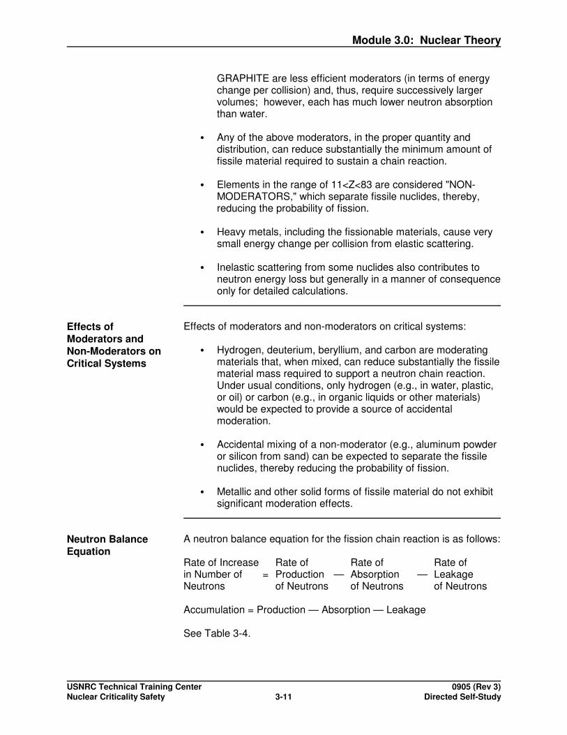
Figure 3-5 shows critical mass of low-enriched uranium (LEU) as afunction of uranium enrichment. Homogeneous and heterogeneousconfigurations are included.
Configurations of low-enrichment uranium are characterized by:
� Higher multiplication (lower critical mass) for optimumheterogeneous systems. This trend continues up to 6 wt%235U.
� Subcriticality of dry systems up to 5 wt%.
Module 3.0: Nuclear Theory
USNRC Technical Training Center 0905 (Rev 3)Nuclear Criticality Safety Directed Self-Study3-17
Figure 3-5. Critical Mass of LEU as a Function of Uranium Enrichment
FINITE SYSTEM
Neutron Balance For the realistic finite system where the effect of leakage isconsidered, the neutron balance becomes:
Production � Absorption + Leakage
and the EFFECTIVE MULTIPLICATION FACTOR keff is defined as:
keff = k =
Comparing this to the earlier definition of keff, it is clear that
keff < k�
with the latter being the absolute maximum multiplication for a givencomposition in a very large system.

Module 3.0: Nuclear Theory
USNRC Technical Training Center 0905 (Rev 3)Nuclear Criticality Safety Directed Self-Study3-18
Comparing the definition of keff to the neutron balance, the valuecorresponding to each CRITICALITY STATE is:
keff = 1 Critical
keff > 1 Supercritical
keff < 1 Subcritical
Reactivity An alternate view of multiplication is through REACTIVITY, which isdefined as:
where then by comparison with keff, � relates to the criticality states asindicated in Table 3-6.
Table 3-6. keff and ���� as Relates to Criticality State
keff ���� Criticality State
= 1 = 0 Critical
> 1 > 0 Supercritical
< 1 < 0 Subcritical
Nuclear CriticalitySafety Practice
In nuclear criticality safety practice, the terms multiplication andreactivity are sometimes used interchangeably (except, of course,where numerical values are involved). This is especially true where aconfiguration of material change could be described as increasing (ordecreasing) either the multiplication or reactivity. Similarly, thechange could be stated as being more (or less) reactive or havinghigher (or lower) multiplication.
Neutron-BalanceTerms
For purposes of nuclear criticality safety, the neutron balance may becontrolled by changing:
� Production
� Absorption
� Leakage
A change in moderation may be noted to have a potential effect oneach of the three terms.

Module 3.0: Nuclear Theory
USNRC Technical Training Center 0905 (Rev 3)Nuclear Criticality Safety Directed Self-Study3-19
Activity 1 - Neutron Balance
Purpose: The purpose of this activity is to identify methods for appropriateadjustment to each of the neutron balance terms (production, absorption,leakage, and moderation).
Directions: Identify methods for appropriate adjustments to each of the neutron balanceterms. Answers are located in the answer key section of the Trainee Guide.
Neutron-Balance Term Method
Production
Absorption
Leakage
Moderation
Module 3.0: Nuclear Theory
USNRC Technical Training Center 0905 (Rev 3)Nuclear Criticality Safety Directed Self-Study3-20
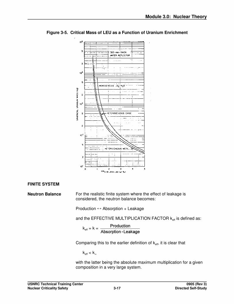
Illustrative Example For an illustrative example, consider the variation of 235U critical massas a function of concentration. (Actual critical mass versusconcentration data for 235U is shown in Figure 3-6 (from LA-10860-MS[Figure 10]).
Figure 3-6. Critical Mass Versus Concentration Data for 235U

Module 3.0: Nuclear Theory
USNRC Technical Training Center 0905 (Rev 3)Nuclear Criticality Safety Directed Self-Study3-21
Consequences/Impacts
Consequences/impacts:
� Masses may have two critical concentrations representingsystems that are:
- undermoderated
- overmoderated
� There is an optimum concentration, where the minimumcritical mass occurs. In this example, the latter mass is morethan 25 times lower than that of the metal sphere; however,the volume is about 13 times greater (Metal: 22.8 kg ÷18.75 kg/liter = 1.30 liter; Solution: ~0.85 kg ÷ ~0.05 kg/liter =17 liter; Solution ÷ Metal = 13).
greatest at high concentration, dropping off as the systembecomes more dilute (and correspondingly larger) withreduced neutron leakage from the outer boundary.
� From the standpoint of nuclear criticality safety, adding waterto a solution excursion would:
- terminate it, if the system is overmoderated
- enhance it (i.e., make it more supercritical), if the system isundermoderated

Module 3.0: Nuclear Theory
USNRC Technical Training Center 0905 (Rev 3)Nuclear Criticality Safety Directed Self-Study3-22
Activity 2 - Operating Limit Values
Purpose: The purpose of this activity is to identify operating limit values.
Directions: Using data from Figure 3-6, complete the second column of the following table. Assuming that "double-batching" is a credible contingency, propose operatinglimit values and record the results in the third column of the table. Answers arelocated in the answer key section of the Trainee Guide.
Situation 235U Physical Limit 235U Operating Limit
Metal, fully reflected criticalmass, kg
Optimum concentration,nominal reflection criticalmass, kg
Optimum concentration, fullyreflected critical mass, kg
"Safe" concentration limit
Results: � Relatively large operating limits (~10 kg) can be used forprocesses that deal with large solid pieces of fissile material orother forms where dryness can be ensured (i.e., under verifiable"moderator control").
� Tight operating limits (~350 g) must be applied where moderatoris not excluded and effective concentration is not controlled.

Module 3.0: Nuclear Theory
USNRC Technical Training Center 0905 (Rev 3)Nuclear Criticality Safety Directed Self-Study3-23
Self-Check Questions 3-2
Answer the following questions. Answers are located in the answer key section of the TraineeGuide.
1. The fission process and its associated neutron chain reaction produce energy that is usedby licensees to do what?
2. The physics of criticality and nuclear criticality safety depends first on the identification ofwhat?
3. What is the basic mechanism for a nuclear reaction?
4. What are some characteristics of scattering reactions?
5. What does absorption reactions–capture and fission–each result in?
6. What must you account for when describing a fission chain reaction?

Module 3.0: Nuclear Theory
USNRC Technical Training Center 0905 (Rev 3)Nuclear Criticality Safety Directed Self-Study3-24
7. What are the advantages and disadvantage of a fission reaction?
8. What are two categories of materials that fission and by what level of neutron energy aretheir isotopes fissioned?
9. What is the dominant fissionable material in NRC licensee fuel cycle facilities?
10. Fission energy release is divided among what fission products?
11. What is the equation for converting total fissions or fission rate in an excursion to anequivalent energy production.
12. What are the consequences of fission energy release to a criticality accident?
13. When fissionable nuclei split into two fission fragments, are the fragments of equal mass?
Module 3.0: Nuclear Theory
USNRC Technical Training Center 0905 (Rev 3)Nuclear Criticality Safety Directed Self-Study3-25
14. What are the consequences of fission products?
15. Neutrons emitted from fission are characterized by what timing?
16. What are two characteristics of neutrons as they relate to a neutron chain reaction?
17. Elastic scattering of neutrons with low-Z or high-Z materials results in what types of energychanges per collision?
18. What moderators in the proper quantity and distribution can reduce substantially theminimum amount of fissile material required to sustain a chain reaction?
19. What effect do non-moderators have in causing fissile material to sustain a chain reaction?
Module 3.0: Nuclear Theory
USNRC Technical Training Center 0905 (Rev 3)Nuclear Criticality Safety Directed Self-Study3-26
20. For each of the following systems, what is the status (increasing, decreasing, or steady) oftheir neutron populations?
If the system is: The neutron population is:Critical
Supercritical
Subcritical
21. The concept of a cross section was developed from what perception?
22. What are some of the key features of energy dependence of microscopic cross sections?
23. The energy-dependent cross-section plots shown in Figure 3-4 for 235U show whatcharacteristics?
24. What does the infinite multiplication factor expression represent?
25. How can the four factor formula be useful?
Module 3.0: Nuclear Theory
USNRC Technical Training Center 0905 (Rev 3)Nuclear Criticality Safety Directed Self-Study3-27
26. Configurations of low-enrichment uranium are characterized by what?
27. Comparing the definition of keff to the neutron balance, what is the value corresponding toeach criticality state below:
keff = 1 Criticality state is keff > 1 Criticality state is keff < 1 Criticality state is
28. An alternative view of multiplication is through what?
29. For purposes of nuclear criticality safety, the neutron balance may be controlled bychanging what?
30. From the standpoint of nuclear criticality safety and over-moderated and under-moderatedsystems, adding water to a solution excursion would do what?
You have completed this section.Please check your progress on the tracking form.
Go to the next section.

Module 3.0: Nuclear Theory
USNRC Technical Training Center 0905 (Rev 3)Nuclear Criticality Safety Directed Self-Study3-28
Learning Objective
When you finish this section, you will be able to:
3.1.4 Identify the purpose and basic features of each of the following hand calculationmethods:
� buckling conversion� age-diffusion migration area approximation� fraction critical� solid angle� surface density
COMPUTATIONALMETHODS
Introduction Before the wide-spread availability of high-speed computers, handcalculation methods were the primary means for determining whetheror not a fissile-material configuration was subcritical. These methodswere based on correlations with experimental data and use ofavailable calculational methods.
The computational methods for nuclear criticality are divided amongthe two approximations that are used to handle neutron leakage.These are diffusion theory and transport theory. Transport theory isfurther divided between discrete ordinates [ sn ] and Monte Carlo.
Diffusion Theory Diffusion theory, the earliest and simplest of the methods, wasdeveloped for systems where the following assumptions about theneutron population and the materials could be sustained:
� Diffusion occurs from regions of high neutron density to those oflow neutron density.
� There is minimal absorption of neutrons.
� There is minimal discontinuity in neutron-reaction properties atinterfaces among materials.
Module 3.0: Nuclear Theory
USNRC Technical Training Center 0905 (Rev 3)Nuclear Criticality Safety Directed Self-Study3-29
With these assumptions, the neutron leakage term could be cast in aform similar to that of a reaction rate as:
Leakage = DB2 �
where
D = Diffusion Coefficient (Material Property)
B2 = Buckling (Geometric Property)
and, in practice,
DB2 = "Macroscopic Leakage Cross Section"
Thus, the neutron balance can be represented as:
��f� = �a� + DB2�
and
keff = k = ��f DB2 + �a
Calculations Usedwith Single Units
The hand calculation methods for single units include:
� Buckling conversion method
� Age-diffusion/migration area approximation
� Fraction critical method
These can be useful (1) for quick assessments, (2) for understandingthe basic nature of some of the processes involved, and (3) as abridge to multi-unit calculations.
Geometric Buckling Geometric buckling (B2) is a measure of the curvature of neutron flux. The larger the value, the greater the curvature. According to thediffusion-theory approximation, any critical configuration of a givenmaterial should have the same buckling. The BUCKLINGCONVERSION METHOD was developed to provide a simple methodfor comparing characteristics of basic shapes. Bucklings for the basicgeometries are shown in Table 3-7.
Module 3.0: Nuclear Theory
USNRC Technical Training Center 0905 (Rev 3)Nuclear Criticality Safety Directed Self-Study3-30
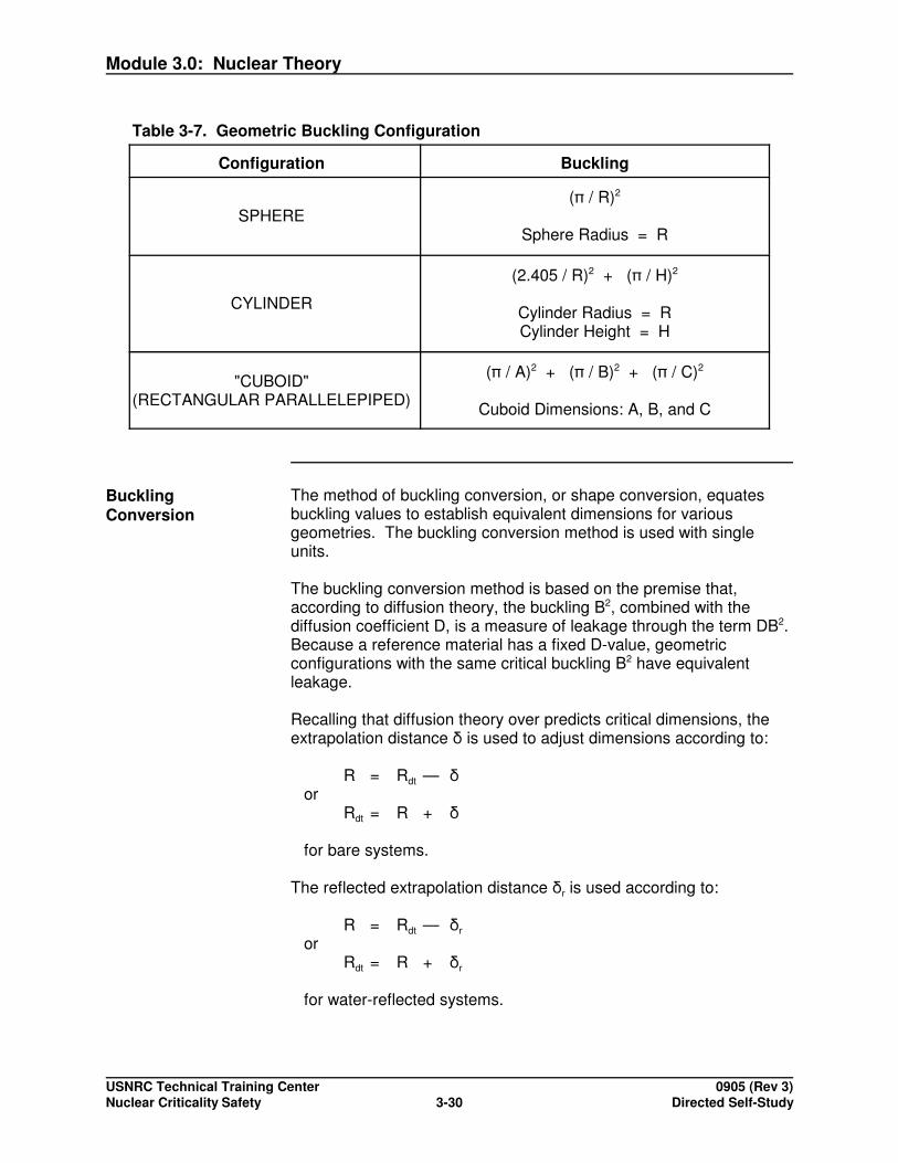
Table 3-7. Geometric Buckling Configuration
Configuration Buckling
SPHERE( / R)2
Sphere Radius = R
CYLINDER
(2.405 / R)2 + ( / H)2
Cylinder Radius = RCylinder Height = H
"CUBOID"(RECTANGULAR PARALLELEPIPED)
( / A)2 + ( / B)2 + ( / C)2
Cuboid Dimensions: A, B, and C
BucklingConversion
The method of buckling conversion, or shape conversion, equatesbuckling values to establish equivalent dimensions for variousgeometries. The buckling conversion method is used with singleunits.
The buckling conversion method is based on the premise that,according to diffusion theory, the buckling B2, combined with thediffusion coefficient D, is a measure of leakage through the term DB2. Because a reference material has a fixed D-value, geometricconfigurations with the same critical buckling B2 have equivalentleakage.
Recalling that diffusion theory over predicts critical dimensions, theextrapolation distance is used to adjust dimensions according to:
R = Rdt — or
Rdt = R +
for bare systems.
The reflected extrapolation distance r is used according to:
R = Rdt — r
orRdt = R + r
for water-reflected systems.
Module 3.0: Nuclear Theory
USNRC Technical Training Center 0905 (Rev 3)Nuclear Criticality Safety Directed Self-Study3-31
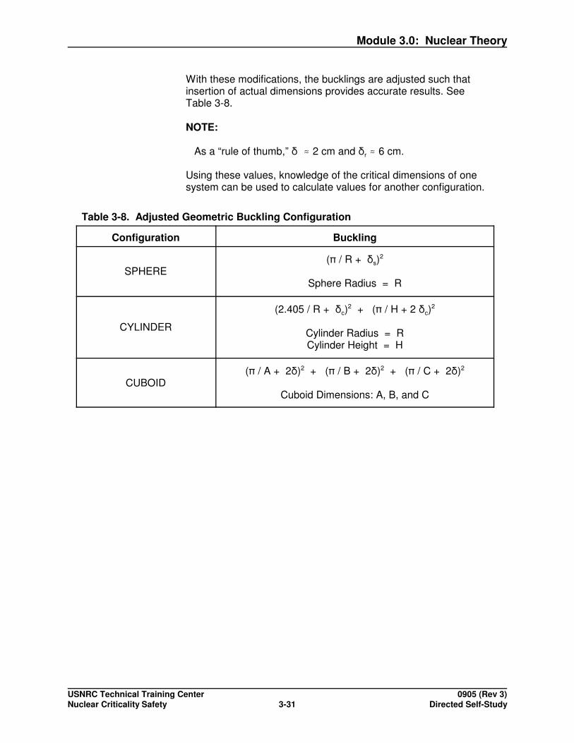
With these modifications, the bucklings are adjusted such thatinsertion of actual dimensions provides accurate results. SeeTable 3-8.
NOTE:
As a “rule of thumb,” � 2 cm and r � 6 cm.
Using these values, knowledge of the critical dimensions of onesystem can be used to calculate values for another configuration.
Table 3-8. Adjusted Geometric Buckling Configuration
Configuration Buckling
SPHERE( / R + s)
2
Sphere Radius = R
CYLINDER
(2.405 / R + c)2 + ( / H + 2 c)
2
Cylinder Radius = RCylinder Height = H
CUBOID( / A + 2)2 + ( / B + 2)2 + ( / C + 2)2
Cuboid Dimensions: A, B, and C

Module 3.0: Nuclear Theory
USNRC Technical Training Center 0905 (Rev 3)Nuclear Criticality Safety Directed Self-Study3-32
Example Calculate the critical radius of a sphere where a critical cylinder 20-cmdiameter by 30-cm high is critical. Assume the sphere and cylinderare reflected and use = 6.0 cm. See Figure 3-7.
Figure 3-7. Calculations for Critical Radius
sphere cylinder
rs = 12.7 cm
ds = 25.4 cm

Module 3.0: Nuclear Theory
USNRC Technical Training Center 0905 (Rev 3)Nuclear Criticality Safety Directed Self-Study3-33
Key Points The buckling conversion method is very simple to apply to the sphereand infinite cylinder and slab geometries, as each is characterized bya single dimension.
Application to finite cylinders and cuboids is more complex becausethe presence of the extrapolation distances prevents simple algebraicinversion of the equations; iterative methods are often required inthese cases.

Module 3.0: Nuclear Theory
USNRC Technical Training Center 0905 (Rev 3)Nuclear Criticality Safety Directed Self-Study3-34
Activity 3 - Buckling Conversion*
*This is an optional activity and is not required for module completion.
Purpose: The purpose of this activity is to provide practice in performingbuckling conversion hand calculations.
Directions: Read the following statement and perform the requested calculations. Space is provided for your computations. Answers are located in the answer key sectionof the Trainee Guide.
Reflected infinite cylinders of homogeneous 3 wt% and 5 wt% hydrogen-moderated uranium have minimum critical infinite-cylinder diameters of 34 cm and 29 cm, respectively.Use r = 6 cm.
1. Calculate the equivalent critical-sphere radius for each.
Module 3.0: Nuclear Theory
USNRC Technical Training Center 0905 (Rev 3)Nuclear Criticality Safety Directed Self-Study3-35
2. Calculate the volume of each sphere and compare the volumes for the two enrichments.
3. Repeat the two calculations for heterogeneous material at the same enrichments where therespective diameters are 25 cm and 22 cm. Also compare the respective volumes amongthe homogeneous and heterogeneous compositions.

Module 3.0: Nuclear Theory
USNRC Technical Training Center 0905 (Rev 3)Nuclear Criticality Safety Directed Self-Study3-36
Six-Factor Formula The following is a modification of diffusion theory. By accounting forneutron leakage, the four-factor formula can be modified into theSIX-FACTOR FORMULA, in which the effective multiplication factorkeff is:
k = k� Pfnl Ptnl
k = � p � f Pfnl Ptnl
where
Pfnl = Fast Non-Leakage ProbabilityPtnl = Thermal Non-Leakage Probability
These latter two terms may be approximated by the AGE-DIFFUSIONCORRELATION consisting of the two terms:
Pfnl = exp (- B2 �)
where
� = (Fermi) Age
� ~ < r2s d > (with r a measure of average distance traveled by
neutrons as they slow from fission energy)
and
where
L = Thermal Diffusion LengthL = (Dt /�at)
½ (with the neutron parameters relating to thermalneutrons and the term again related to averagedistance of neutron travel, this time after becominga thermal neutron)
Although the fast non-leakage probability is derived based onassumptions of a large system with continuous moderation (not acharacteristic of water-moderated systems) and the thermalnon-leakage probability formulation suffers from the limitations ofdiffusion theory in general, the expressions have been found to be auseful basis for empirical formulations.
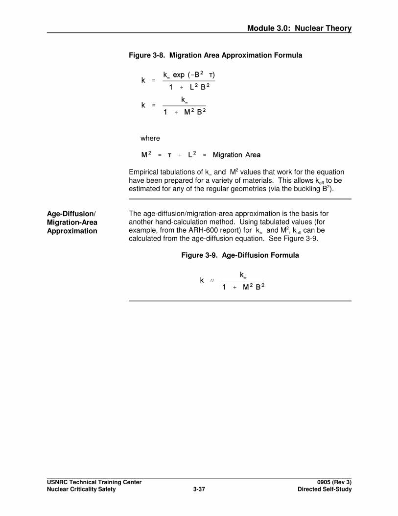
One expression developed by combining the two terms into theMIGRATION AREA APPROXIMATION is shown in Figure 3-8.
Module 3.0: Nuclear Theory
USNRC Technical Training Center 0905 (Rev 3)Nuclear Criticality Safety Directed Self-Study3-37
Figure 3-8. Migration Area Approximation Formula
where
Empirical tabulations of k� and M2 values that work for the equationhave been prepared for a variety of materials. This allows keff to beestimated for any of the regular geometries (via the buckling B2).
Age-Diffusion/Migration-AreaApproximation
The age-diffusion/migration-area approximation is the basis foranother hand-calculation method. Using tabulated values (forexample, from the ARH-600 report) for k� and M2, keff can becalculated from the age-diffusion equation. See Figure 3-9.
Figure 3-9. Age-Diffusion Formula

Module 3.0: Nuclear Theory
USNRC Technical Training Center 0905 (Rev 3)Nuclear Criticality Safety Directed Self-Study3-38
Activity 4 - Migration-Area Approximation*
*This is an optional activity and is not required for module completion.
Purpose: The purpose of this activity is to provide practice in performingmigration-area approximation hand calculations.
Directions: Read the following statements and perform the requested calculations. Answersare located in the answer key section of the Trainee Guide.
1. 4 wt%-enriched UO2 moderated uniformly with 75 vol% water has k� = 1.395 andM2 = 28.5 cm2.
For c = 2.1 cm, calculate keff for a can 30 inches high by 10 inches diameter.
2. Repeat the above calculation for a can 40 inches high.

Module 3.0: Nuclear Theory
USNRC Technical Training Center 0905 (Rev 3)Nuclear Criticality Safety Directed Self-Study3-39
3. Calculate the maximum keff for a 10-inch diameter cylinder of the reference material.
4. Assuming the reference material is optimally moderated, estimate the diameter for afavorable geometry cylinder (reflected keff = 0.90, = 6.0 cm).

Module 3.0: Nuclear Theory
USNRC Technical Training Center 0905 (Rev 3)Nuclear Criticality Safety Directed Self-Study3-40
Fraction CriticalMethod
Another single-unit hand calculation is the fraction critical. It issometimes applied directly (for example, setting a limit at 80% of acritical mass). It is also used in array calculations such as the surfacedensity method described next.
One formulation for a specified material is:
f = Fraction Critical = Mass of Uranium in Unit Mass of Uranium in Critical Sphere

Module 3.0: Nuclear Theory
USNRC Technical Training Center 0905 (Rev 3)Nuclear Criticality Safety Directed Self-Study3-41
Activity 5 - Fraction Critical*
*This is an optional activity and is not required for module completion.
Purpose: The purpose of this activity is to provide practice in performingfraction critical hand calculations.
Directions: Calculate the fraction critical. Space is provided for your computations. Answersare located in the answer key section of the Trainee Guide.
Hint:
Mass of Uranium in Unit = (Unit Volume) x (density) x (UO2 fraction) x (U fraction in UO2)
Mass of Uranium in Critical Sphere = (Sphere Volume) x (density) x (UOx fraction) x (U fraction in UO2)
1. The material in the 30-inch high x 10-inch diameter storage unit in the previous activity hasa density of 10.96 g UO /cm3, volume fraction of uranium dioxide of 0.25, and uraniumfraction (in UO2) of 0.88. The radius of a critical sphere of the material is 25.4 cm.

Module 3.0: Nuclear Theory
USNRC Technical Training Center 0905 (Rev 3)Nuclear Criticality Safety Directed Self-Study3-42
2. Repeat the calculation for a 40 inch-high storage unit.
3. Calculate the height of container with f = 0.73 (the maximum allowed by the surface densitymodel discussed next).

Module 3.0: Nuclear Theory
USNRC Technical Training Center 0905 (Rev 3)Nuclear Criticality Safety Directed Self-Study3-43
Calculations Usedwith Arrays
The two hand calculation methods considered here for arrays areboth based on correlations with experimental data and/or calculations. They predict subcritical configurations, not specific values of keff.
Uses and limitations are noted through the activities.
Surface DensityMethod
The surface density method judges subcriticality of a facility loading(in mass per unit area) of fissile material by comparison to that of acritical reflected infinite slab of the same material. (The followingdevelopment is based on TID 7016 Rev. 2.)
Using the definition of fraction critical f provided previously:
� = 0.54 �0 (1 - 1.37 f)
where
� = "Allowed" Surface Density�0 = Surface Density of Critical Water-Reflected Infinite Slab f = Fraction Critical of Unit
with the restriction that f < 0.73.
For an array of stacked units with uniform center-to-center spacing,see Figure 3-10.
� = n m d2
where
n = Number of Units in Stackm = Mass of Fissionable Material in Unitsd = Center-to-Center Spacing (Cell Length)
[d2 � Area for Non-Cubic Cell]
with a minimum surface-to-surface spacing of 0.3 m.
Combining these expressions:
d = 1.37 [ n m /�0 (1 - 1.37 f)]½
Although developed here for a regular array of identical units, themethod is far more flexible. In practice, any units or pieces ofequipment can be interchanged freely so long as each meets thesurface density criteria regardless of arrangement (that is, the fractioncritical limit is not exceeded and the associated area allows thesurface density limit to be met). See Figure 3-11 which is an exampleof a calculation using the surface density method.
Module 3.0: Nuclear Theory
USNRC Technical Training Center 0905 (Rev 3)Nuclear Criticality Safety Directed Self-Study3-44
Figure 3-10. Surface Density Method
Figure 3-11. Example of Calculation Using the Surface Density Method
n = 2
m = 10 kg = 10000 g
d = 48.8 (cm) = 19.2 in f = 0.5

Module 3.0: Nuclear Theory
USNRC Technical Training Center 0905 (Rev 3)Nuclear Criticality Safety Directed Self-Study3-45
Key Points Key points for the surface density method:
� By use of the surface density method, consistent changes can bemade readily (such as going from a one-high to a five-high arrayby modifying the floor spacing and ensuring appropriate verticalseparation).
� Because the comparison is to an infinite slab, each array layermay be of unlimited extent. This is convenient, but may beexcessively conservative to apply to a relatively small number ofunits.
� The concept of surface density is useful for picturing relatedphysical phenomena and may still be found in safety analysisreports, even when computer calculations are the actual basis forjudging subcritical configurations.

Module 3.0: Nuclear Theory
USNRC Technical Training Center 0905 (Rev 3)Nuclear Criticality Safety Directed Self-Study3-46
Activity 6 - Surface Density*
*This is an optional activity and is not required for module completion.
Purpose: The purpose of this activity is to provide practice in performing surfacedensity hand calculations.
Directions: Read the following statement and perform the requested calculation. Space isprovided for your computations. Answers are located in the answer key section ofthe Trainee Guide.
The material, whose fraction critical f was calculated in the previous activity for a 10-inchdiameter x 30-inch high can, has a critical surface density of 33.0 U g/cm2.
HINT: d = 1.37 [n m 0 (1 - 1.37f)]1/2
1. Determine the minimum center-to-center spacing allowed by the surface-density method foran array of one unit high.

Module 3.0: Nuclear Theory
USNRC Technical Training Center 0905 (Rev 3)Nuclear Criticality Safety Directed Self-Study3-47
2. Determine how the spacing would need to be modified to have the array 2 through 5 unitshigh instead.

Module 3.0: Nuclear Theory
USNRC Technical Training Center 0905 (Rev 3)Nuclear Criticality Safety Directed Self-Study3-48
•
• •
•
•
•
• •
•
•
•
•
Solid Angle Method The solid angle method can be used to judge subcriticality of arraysfor which the keff of a single unit is known.
Interaction probability is correlated to the solid angle subtended froma central unit to all surrounding units. See Figure 3-12.
According to the formulation from TID 7016 Rev. 2.
�allowed = 9 - 10 keff
where
• keff < 0.80
• The individual unit is subcritical when fully reflected by water.
• Center-to-center spacing is > 0.3 m.
• �allowed < 6 steradians (sr)
Figure 3-12. Solid Angle Method
Precisesolid angles are complex to calculate (for example, using multiple-parameter integration). See Figure 3-13. Thus, it is common to useapproximations.
One example is the "point-to-cylinder" approximation, where the solidangle is calculated from the center of a unit to a plane with the heightand diameter of the cylinder tangent to it at the point closest to thecentral unit. See Figure 3-14.

Module 3.0: Nuclear Theory
USNRC Technical Training Center 0905 (Rev 3)Nuclear Criticality Safety Directed Self-Study3-49
D
P. H
L2
L2
Figure 3-13. Solid Angle Method Formula
Figure 3-14. Point-to-Cylinder
where
L = Length of the cylinderD = Diameter of the cylinderH = Distance from the point to the surface
of the cylinder

Module 3.0: Nuclear Theory
USNRC Technical Training Center 0905 (Rev 3)Nuclear Criticality Safety Directed Self-Study3-50
. .H
X
Example This example illustrates the use of solid angle calculations.
keff = 0.777�allowed = 9 -10 (0.777) = 1.23
L = 30 in.D = 10 in. H =
Iterative Process
x = 45 0.1756x = 40 0.2251 Interpolatex = 35 0.2981 �������x = 30 0.4116 ������������ 34.5 inchesx = 34 0.3168 �������x = 34.5 0.3073
Key Points Key points for solid angle calculations:
� The solid angle method does not require identical units or regularspacing. Thus, it has been used for a variety of configurationswith storage units and plant equipment and may still bereferenced in safety analysis reports.
� The concept of neutron interaction relating to the solid angle isintuitive. Thus, the method (as noted earlier for surface density)can be a useful tool in thinking about and understanding computercalculations.
� The method is complex algebraically. Thus a small computerprogram is often applied.

Module 3.0: Nuclear Theory
USNRC Technical Training Center 0905 (Rev 3)Nuclear Criticality Safety Directed Self-Study3-51
.. .
H}H}X
X
Activity 7 - Solid Angle*
*This is an optional activity and is not required for module completion.
Purpose: The purpose of this activity is to provide practice in performing solidangle hand calculations in determining maximum keff.
Directions: Read the following statements and perform the requested calculations. Space isprovided for your computations. Answers are located in the answer key section ofthe Trainee Guide.
Consider a regular three-by-three array of the 10-inch diameter by 30-inch high units (describedin the earlier activity using the migration-area method). Center-to-center spacing from thecentral unit to each of its four nearest neighbors is X = 42 inches.
Use the point-to-cylinder approximation given above to calculate solid angles.
HINT:
� =
L = 30 in
D = 10 in
H =
H1 = X1 -
Module 3.0: Nuclear Theory
USNRC Technical Training Center 0905 (Rev 3)Nuclear Criticality Safety Directed Self-Study3-52
1. Demonstrate that the array satisfies the solid angle criteria.
2. Determine the maximum allowed keff that the unit could have for the given spacing.

Module 3.0: Nuclear Theory
USNRC Technical Training Center 0905 (Rev 3)Nuclear Criticality Safety Directed Self-Study3-53
Activity 8 - Solid Angle*
*This is an optional activity and is not required for module completion.
Purpose: The purpose of this activity is to provide practice in performing solidangle hand calculations in determining allowed spacing between units.
Directions: Read the following statements and perform the requested calculations. Space isprovided for your computations. Answers are located in the answer key section ofthe Trainee Guide.
1. Determine allowed spacing for a 10-inch diameter x 40-inch high cylindrical can.

Module 3.0: Nuclear Theory
USNRC Technical Training Center 0905 (Rev 3)Nuclear Criticality Safety Directed Self-Study3-54
2. What would be required to calculate a multilevel array?

Module 3.0: Nuclear Theory
USNRC Technical Training Center 0905 (Rev 3)Nuclear Criticality Safety Directed Self-Study3-55
Self-Check Questions 3-3
Fill in the missing words in each statement. Answers are located in the answer key section ofthe Trainee Guide. Choose from the following words:
buckling identical units shapesconservative infinite slabdiffusion-theory approximation intuitive solid angleextrapolation distances leakage subcriticalfloor spacing low surface densityfraction critical neutron leakage unitshigh point-to-cylinder vertical
1. In diffusion theory, assumptions are that diffusion occurs from regions of neutron density to those of neutron density, that there is minimal absorption ofneutrons, and that there is minimal discontinuity in neutron-reaction properties at interfacesamong materials.
2. Hand calculation methods for single include the buckling conversionmethod, age-diffusion/migration area approximation, and the fraction critical method.
3. Geometric is a measure of the curvature of neutron flux.
4. According to the , any criticalconfiguration of a given material should have the same buckling.
5. The buckling conversion method was developed to provide a simple method for comparingcharacteristics of basic .
6. Because a reference material has a fixed diffusion coefficient D-value, geometricconfigurations with the same critical buckling have equivalent .
7. The buckling conversion method is very simple to apply to the sphere and cylinder and geometries, as each is characterized by a single dimension.
8. Application to finite cylinders and cuboids is more complex because the presence of the prevents simple algebraic inversion of the equations;iterative methods are often required in these cases.
9. By accounting for , the four-factor formula can be modifiedinto the six-factor formula.
10. The method is sometimes applied directly (for example,setting a limit at 80% of a critical mass). It is also used in array calculations, such as thesurface density method.
11. The method judges subcriticality of a facility loading

Module 3.0: Nuclear Theory
USNRC Technical Training Center 0905 (Rev 3)Nuclear Criticality Safety Directed Self-Study3-56
(in mass per unit area) of fissile material by comparison to that of a critical reflectedinfinite slab of the same material.
12. Use of the surface density formulation, allows consistent changes to be made readily, suchas going from a one-high to a five-high array by modifying the and ensuring appropriate separation.
13. Because the comparison is to an infinite slab, each array layer may be of unlimited extent. This is convenient, but may be excessively to apply to arelatively small number of units.
14. The concept of surface density is useful for picturing related physical phenomena and maystill be found in safety analysis reports, even when computer calculations are the actualbasis for judging configurations.
15. The method can be used to judge subcriticality of arraysfor which the keff of a single unit is known.
16. One example of a solid angle calculation is the approximation where the solid angle is calculated from the center of a unit to a plane withthe height and diameter of the cylinder tangent to it at the point closest to the central unit.
17. The solid angle method does not require or regularspacing.
18. The concept of neutron interaction relating to the solid angle is .
You have completed this section.Please check off your progress on the tracking form.
Go to the next section.

Module 3.0: Nuclear Theory
USNRC Technical Training Center 0905 (Rev 3)Nuclear Criticality Safety Directed Self-Study3-57
Learning Objective
When you finish this section you will be able to:
3.1.5.a Discuss the importance of validation to determining criticality safety limits.
3.1.5.b Define the two major computational methods used in criticality safety codes.
3.1.5.c Define the assumption used in Finite Difference Methods to eliminate timedependencies and the implication this assumption has on bias of these methods.
3.1.5.d Define the technique used by Monte Carlo techniques to solve the time-dependentneutron transport equation.
3.1.5.e Describe the geometry approach used in KENO and MONK and the geometryapproach used in MCNP.
3.1.5.f Describe the difference between treatment of resonances in KENO versus thetreatment used in MCNP and MONK.
COMPUTER CODES
Introduction In the 21st Century, computing machines and numerical models(programs or codes) have all but replaced critical experiments orhand calculations in the determination of criticality safety limits. A fewexamples of these programs include XSDRNPM, DORT, TORT,KENO, MCNP, and MONK. The method selected must be versatile toencompass a wide variety of configurations/compositions and be ableto reproduce all neutron processes that occur in the real systems.
Validation, Bias,and BiasUncertainty
Per 10 CFR 70.61, computer codes used for determining nuclearcriticality safety requirements must be validated against experimentsof similar configurations and materials to determine a bias and biasuncertainty.
From NUREG/CR-6698:“For use in safety related analyses, the ability of a calculationalmethodology to accurately predict the subcriticality of a system mustbe well understood. The understanding of a calculationalmethodology’s bias in predicting subcritical systems is obtainedthrough the validation process. Validation includes identification ofthe difference between calculated and experimental results. Thisdifference, called the bias, and uncertainty associated with the bias

Module 3.0: Nuclear Theory
USNRC Technical Training Center 0905 (Rev 3)Nuclear Criticality Safety Directed Self-Study3-58
are used in combination with additional subcritical margin to establishan upper safety limit (USL). Subcriticality is assured if calculatedresults are below the USL and within the area of applicability for thevalidation.”As described in ANSI/ANS 8.1, a validation report will:
1) Describe the method used to validate the code in a manner whichwill allow independent duplication of results.
2) Describe the computer platform (hardware, software, and othersupport equipment).
3) Describe the code, including any options, as well as the crosssection sets and any other numerical parameters.
4) Identify the experimental data.5) List the areas of applicability. For example, metal system versus
compounds; dry system versus moderated.6) State the bias and the prescribed margin of safety over the areas
of applicability.
ComputationalTools
The majority of the computational tools used to calculate criticalconditions can be distinguished as either Finite Difference methods orMonte Carlo methods.
Finite DifferenceMethods
XSDRNPM, DORT, and TORT use numerical methods thatapproximate the neutron transport equations by using finite differenceequations. This approach produces a set of differential/algebraicequations relating the neutron flux at a point to the neutron fluxes atthe surrounding points. These differential/algebraic equations includeboth space and energy dependences. It is important to note thatthese methods use the assumption that keff = 1.00 and eliminate timedependency by modifying the transport equation with apseudo-absorption macroscopic cross section that is a function of keff. These programs assume (or allow the user to input) an initial fluxdistribution. The differential/algebraic equations are solved using theinitial neutron flux and keff to determine a new flux and keff . Theresults are used to define the source distribution in a second iteration. The flux distributions are compared and the iteration repeated untilconvergence. However, the final keff may not equal one, and the biasand the uncertainty in the bias depend on the closeness of keff to1.00. These programs run quickly on computers, but theapproximations and flux convergence techniques used lead tounavoidable limitations.
Monte CarloMethods
KENO, MCNP, and MONK use Monte Carlo techniques to solve thetime-dependent neutron transport equation by tracking thetime-dependent neutron life cycles as they interact with materials

Module 3.0: Nuclear Theory
USNRC Technical Training Center 0905 (Rev 3)Nuclear Criticality Safety Directed Self-Study3-59
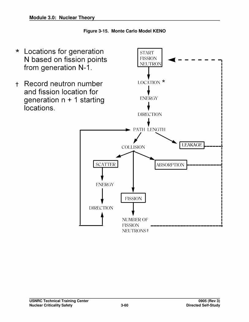
according to the physical probabilities inherent in the formulation ofthe neutron cross sections. Figure 3-15 is a representation of theprocess as it is applied in KENO. Geometric configurations andmaterials are specified, parameters and reaction rates are recorded,and statistical results for multiplication factor, flux, or othercharacteristics are developed. Statistical biasing or weightingtechniques can increase the efficiency of these calculations.
In the context of nuclear criticality safety, the Monte Carlo KENOprocedure is applied by developing a model that is capable of"tracking" individual (fictitious) neutrons through a material mediumcontaining fissile and other species for each life cycle. The accuracyof the result is inversely proportional to the square root of the numberof life cycles. Thus, running more tracks or groups of tracks willalways improve the accuracy of your results. The life cycles are runin groups. Each group typically uses a fission source distributionbased on the previous group’s neutron interaction distribution. Eachgroup is started with the same number of life cycles. Thus severalmeasures, like the number of fission absorptions, can be used todetermine a keff for each group. Typically, the initial group-to-groupkeff changes are large, and the cumulative keff ignore these “start-up”values. Additional groups are run until the cumulative keff hasconverged. The output reports a value for keff and a standarddeviation (�) value, which is a measure of confidence in the answer. The range keff ± � is ascribed a 67% certainty of containing the "real"answer, while keff ± 2� is ascribed a 95% certainty. These programstake more computer time to complete; however, these programs canhandle complicated three-dimensional (3-D) geometries.
Module 3.0: Nuclear Theory
USNRC Technical Training Center 0905 (Rev 3)Nuclear Criticality Safety Directed Self-Study3-60
Figure 3-15. Monte Carlo Model KENO

Module 3.0: Nuclear Theory
USNRC Technical Training Center 0905 (Rev 3)Nuclear Criticality Safety Directed Self-Study3-61
KENO KENO V.a is a multi-group Monte Carlo criticality program used tocalculate the keff of a 3-D system. Special features include simplifieddata input and the ability to specify origins for spherical and cylindricalgeometry regions. A large portion of the data has been assigneddefault values that have been found to be adequate for manyproblems. This feature enables the user to run a problem with aminimum of input data.
KENO V.a geometry is restricted to the use of specific shapes. These shapes are called geometry regions. Allowed shapes arecubes, cuboids (rectangular parallelepipeds), spheres, cylinders,hemispheres, and hemi-cylinders. In KENO V.a, the sense of anylocation with respect to a shape is defined as positive everywhereinside the shape and negative everywhere outside. These shapesmust be oriented along orthogonal axes and cannot be rotated. Theycan be translated. Hemispheres and hemi-cylinders are not limited tohalf-spheres and half-cylinders; the definitive plane can be positionedby entering a chord. The value of this chord can range from thepositive magnitude of the radius (giving a complete sphere orcylinder) to the negative magnitude of the radius (giving a zerovolume, nonexistent sphere, or cylinder).
A major restriction applied to KENO V.a geometry is that intersectionsare not allowed. Furthermore, each successive geometry region mustcompletely enclose the preceding region. To alleviate the completeenclosure restriction, KENO V.a allows multiple sets of geometryregions with each set independently governed by this restriction. Each set of these multiple geometry regions are called units. Unitscan be stacked together in a 3-D rectangular parallelepiped called anarray or lattice just as children's blocks can be stacked. Units that areto be stacked together in this manner must have a rectangularparallelepiped outer region and the adjacent faces of adjacent unitsmust be the same size and shape. An array can be treated as abuilding block and be used as a unit within another array.
The use of holes in KENO V.a allows a unit to be placed withinanother unit, thereby alleviating the restriction that each region withina unit must completely enclose all preceding regions within that unit. However, a hole is not allowed to intersect other holes or regions. Aunit that is to be used as a hole need not have a rectangularparallelepiped as its outer boundary.
KENO V.a provides four types of boundary conditions that areaccepted for performing criticality safety analyses. The defaultboundary condition is a vacuum where when neutrons leave they aregone forever. Three options are available for replacing the vacuumcondition. The options are mirror reflection where neutrons leavingare returned as a mirror image, periodic where neutrons leaving arereturned to the opposite face, and white where an isotropic return isimposed at the boundary. A fifth type of boundary condition, albedo,has not been thoroughly tested for use in criticality safety evaluations.

Module 3.0: Nuclear Theory
USNRC Technical Training Center 0905 (Rev 3)Nuclear Criticality Safety Directed Self-Study3-62
KENO V.a is part of the Criticality Safety Analysis Sequence (CSAS)process procedure provided with SCALE. The CSAS process crosssections are generated using the Bondarenko method (via BONAMI)and either the Nordheim integral method (via NITAWL-III) orcollapsing of pointwise continuous cross sections using aproblem-dependent pointwise continuous flux (via WORKER,CENTRM and PMC) to provide a resonance-corrected cross-sectionlibrary based on the physical characteristics of the problem beinganalyzed. This cross-section library can be utilized by KENO V.a (a3-D multi-group Monte Carlo criticality program) or XSDRNPM (aone-dimensional (1-D) discrete-ordinates code for transport analysis). The CSAS4 process procedure provides search capabilities utilizingKENO V.a. When CSAS4 is specified a parameter search isperformed on keff as a function of dimensions or densities. The twobasic search options offered are (1) an optimum search seeking amaximum or minimum value of keff and (2) a critical search seeking afixed value of keff .
MCNP MCNP is a general-purpose Monte Carlo N-Particle code that can beused for neutron, photon, electron, or coupledneutron/photon/electron transport. Specific areas of applicationinclude, but are not limited to, radiation protection and dosimetry,radiation shielding, radiography, medical physics, nuclear criticalitysafety, detector design and analysis, nuclear oil well logging,accelerator target design, fission and fusion reactor design,decontamination and decommissioning. The code treats an arbitrary3-D configuration of materials in geometric cells bounded by first- andsecond-degree surfaces and fourth-degree elliptical tori.
The geometry of MCNP treats an arbitrary 3-D configuration of userdefined materials in geometric cells bounded by first- andsecond-degree surfaces and fourth-degree elliptical tori. Theorientation with respect to surfaces defining a cell is definedmathematically as any location for which the surface equation isnegative is considered to be inside and any location for which thesurface equation is positive is outside (i.e., a negative sign precedinga surface number means that the cell defined by that surface is aregion of space having a negative sense with respect to that surface). For example, space that is outside a 3-D body (e.g., a sphere) orabove or to the right of a plane has a positive sense, and vice versa. The cells are defined by the intersections, unions, and complementsof the regions bounded by the surfaces. Surfaces are defined bysupplying coefficients to the analytic surface equations or, for certaintypes of surfaces, known points on the surfaces.
Cells can be repeated using “LIKE m BUT” capabilities to repeat cellm (i.e., “like m”), but moved to a different location and/or differentorientation. Lattice arrays of cells can be formed from hexahedra(solids with six faces) and hexagonal prisms (solids with eight faces)
Module 3.0: Nuclear Theory
USNRC Technical Training Center 0905 (Rev 3)Nuclear Criticality Safety Directed Self-Study3-63
using the “LAT” (for lattice array) capabilities. These lattice arraysextend infinitely in all directions, but can be truncated after beingdesignated as a universe and used to fill a cell of finite dimensions.
Repeated-structure capabilities make it possible to describe, onlyonce, the cells and surfaces of a structure that appears more thanonce in the geometry. One example of such a structure is a reactorcore that has dozens of nearly identical fuel modules. Therepeated-structure capability extends the concept of an MCNP cell. The user can specify that a cell is to be filled with something called auniverse. A universe is either a lattice or an arbitrary collection ofcells. A single universe, described only once, can be designated to filleach of any number of cells in the geometry. Some or all of the cellsin a universe may themselves be filled with universes.
MCNP provides four types of boundary conditions that are acceptedfor performing criticality safety analyses. The default boundarycondition is a vacuum where neutrons leaving enter a region of zeroneutron importance. Three options are available for replacing thevacuum condition. The options are mirror reflection where neutronsleaving are returned as a mirror image, periodic where neutronsleaving are returned to the opposite face, and white where anisotropic return is imposed at the boundary. However, using reflectiveplanes make it difficult (or even impossible) to get the correct answer. The user is cautioned to check the source weight and tallies to ensurethat the desired result is achieved.
Point-wise cross-section data typically are used, although group-wisedata also are available. For neutrons, all reactions given in aparticular cross-section evaluation (such as ENDF/B-VI) are available. Resonance data is used directly to determine resonance escapeprobabilities that are sampled during slowing-down through theresonance energy.
MONK The origins of MONK can be traced to a code called GEM, whichcame out of the post-war nuclear weapons program in the UnitedKingdom (UK). A more recent major program of develop wasstimulated by the criticality needs of the UK reprocessing industry andresulted in the production of MONK6 in the late 1980s.
A MONK system model is assembled from simpler sub-systems usingthe MONK geometry package. The basic component of this packageis a set of simple bodies, including the sphere, box, rod, prism, coneand torus. In MONK, the sense of any location with respect to a bodyis defined as positive everywhere inside the body and negativeeverywhere outside. These bodies can have general orientation andoverlap each other if necessary. They are used as basic buildingblocks to form simple parts of the geometry, each part being definedquite independently of the rest of the system using local coordinates. These simple parts are then used to make more coupled parts in the

Module 3.0: Nuclear Theory
USNRC Technical Training Center 0905 (Rev 3)Nuclear Criticality Safety Directed Self-Study3-64
same way and so on, until the system is assembled. Hole geometries(making use of a technique called Woodcock tracking) are usedextensively in MONK to provide a lot of complicated fine geometricdetails and to short-cut the specification of some of the commonlyoccurring array items.
MONK provides four types of boundary conditions that are acceptedfor performing criticality safety analyses. The default boundarycondition is a free (“black”) boundary where neutrons leaving enter aregion of zero neutron importance. Three options are available forreplacing the free boundary condition. The options are specularreflection where neutrons leaving are returned as a mirror image,periodic where neutrons leaving are returned to the opposite face,and a forward peaked (cos2) distribution of returning particles aboutthe surface normal.
For criticality calculations, neutron interactions are considered in theMONK collision processing package called DICE. The standardMONK nuclear data library is a hyper-fine 8,220-group library basedon UKNDL and JEF evaluations. Resonance data is used directly todetermine resonance escape probabilities that are sampled duringslowing down through the resonance energy. This library, togetherwith the point-energy collision processing algorithms, provides a verydetailed modeling of the physics. For comparisons to SCALE, MONKcan also accept multi-group data from the SCALE libraries.

Module 3.0: Nuclear Theory
USNRC Technical Training Center 0905 (Rev 3)Nuclear Criticality Safety Directed Self-Study3-65
Self-Check Questions 3-4
Complete the following questions. Answers are located in the answer key section of theTrainee Guide.
1. What is importance of the validation process to determining criticality safety limits?
2. What are two major computational methods used in criticality safety codes?
3. What assumption is used in Finite Difference Methods to eliminate time dependencies andhow does this assumption affect the bias of these methods?
4. How do Monte Carlo techniques solve the time-dependent neutron transport equation?

Module 3.0: Nuclear Theory
USNRC Technical Training Center 0905 (Rev 3)Nuclear Criticality Safety Directed Self-Study3-66
5. What geometry approach is used in KENO and MONK and what geometry approach isused in MCNP?
6. What is the difference between treatment of resonances in KENO versus the treatmentused in MCNP and MONK?
Module 3.0: Nuclear Theory
USNRC Technical Training Center 0905 (Rev 3)Nuclear Criticality Safety Directed Self-Study3-67
Progress Review Meeting Form
It's time to schedule a progress meeting with your administrator. Review theprogress meeting form on the next page. In Part III, As a Regulator, write yourspecific questions to discuss with the administrator.
DateScheduled:_________________________________Location:______________________
I. The following suggested items should be discussed with the administrator as to howthey pertain to your current position:
� Nuclear reactions
� Cross section
� Infinite systems
� Finite systems
� Computational methods:- Buckling conversion- Age-diffusion migration area approximation- Fraction critical
� Monte Carlo computer code KENO
� Validation report

Module 3.0: Nuclear Theory
USNRC Technical Training Center 0905 (Rev 3)Nuclear Criticality Safety Directed Self-Study3-68
II. Use the space below to take notes during your meeting.

Module 3.0: Nuclear Theory
USNRC Technical Training Center 0905 (Rev 3)Nuclear Criticality Safety Directed Self-Study3-69
III. As a Regulator:
� How are hand calculations used today?
� What other classes or short courses are available to me if I wish to learn more?
� Do we have the capability of performing computer calculations?
� How would I review an analysis provided to me and how in depth am I expected to gowith it?
� Determining the reactivity of a system is one thing, but how is nuclear criticality safetyimplemented in the field?
� What specific computer code(s) should I be familiar with as a regulator?
Use the space below to write your specific questions.
IV. Further assignments? If yes, please note and complete. If no, initial completion ofprogress meeting on tracking form.
Module 3.0: Nuclear Theory
USNRC Technical Training Center 0905 (Rev 3)Nuclear Criticality Safety Directed Self-Study3-70
Ensure that you and your administrator have dated and initialed your progress on yourtracking form for this module. Go to the module summary.
MODULE SUMMARY The physics of criticality and nuclear criticality safety depends first onidentification of nuclear reactions. Neutron reactions are the majorcontributors to fission chain reactions. The dominant fissionablematerial in NRC licensee fuel cycle facilities is uranium. Hydrogen,deuterium, beryllium, and carbon are moderating materials that, whenmixed, can reduce substantially the required fissile material massrequired to support a neutron chain reaction. To predict the effect ofa change in material composition or configuration, numerouscomputational methods have been used at fuel cycle facilities. Themethod selected must be versatile enough to encompass a widevariety of compositions and be able to reproduce effects of allneutronic processes that occur in real systems.
Congratulations! You are ready to go to the next assigned module.