nsrp no. 0297 march 1990 - apps.dtic.mil
TRANSCRIPT
NSRP No. 0297March 1990
THE NATIONAL SHIPBUILDING
RESEARCH PROGRAM
FLAME BENDING OF PIPEFOR
ALIGNMENT CONTROL
PANEL SP-7 PROJECT REPORT
This project was performed by Puget Sound Naval Shipyard undersub-contract from Ingalls Shipbuilding, Inc. Funds were providedby the U. S. Navy and the Maritime Administration of the U. S.
Report Documentation Page Form ApprovedOMB No. 0704-0188
Public reporting burden for the collection of information is estimated to average 1 hour per response, including the time for reviewing instructions, searching existing data sources, gathering andmaintaining the data needed, and completing and reviewing the collection of information. Send comments regarding this burden estimate or any other aspect of this collection of information,including suggestions for reducing this burden, to Washington Headquarters Services, Directorate for Information Operations and Reports, 1215 Jefferson Davis Highway, Suite 1204, ArlingtonVA 22202-4302. Respondents should be aware that notwithstanding any other provision of law, no person shall be subject to a penalty for failing to comply with a collection of information if itdoes not display a currently valid OMB control number.
1. REPORT DATE MAR 1990
2. REPORT TYPE N/A
3. DATES COVERED -
4. TITLE AND SUBTITLE The National Shipbuilding Research Program, Flame Bending of Pipe forAlignment Control Panel Sp-7 Project Report
5a. CONTRACT NUMBER
5b. GRANT NUMBER
5c. PROGRAM ELEMENT NUMBER
6. AUTHOR(S) 5d. PROJECT NUMBER
5e. TASK NUMBER
5f. WORK UNIT NUMBER
7. PERFORMING ORGANIZATION NAME(S) AND ADDRESS(ES) Naval Surface Warfare Center CD Code 2230 - Design Integration ToolsBuilding 192 Room 128 9500 MacArthur Blvd Bethesda, MD 20817-5700
8. PERFORMING ORGANIZATIONREPORT NUMBER
9. SPONSORING/MONITORING AGENCY NAME(S) AND ADDRESS(ES) 10. SPONSOR/MONITOR’S ACRONYM(S)
11. SPONSOR/MONITOR’S REPORT NUMBER(S)
12. DISTRIBUTION/AVAILABILITY STATEMENT Approved for public release, distribution unlimited
13. SUPPLEMENTARY NOTES
14. ABSTRACT
15. SUBJECT TERMS
16. SECURITY CLASSIFICATION OF: 17. LIMITATION OF ABSTRACT
SAR
18. NUMBEROF PAGES
162
19a. NAME OFRESPONSIBLE PERSON
a. REPORT unclassified
b. ABSTRACT unclassified
c. THIS PAGE unclassified
Standard Form 298 (Rev. 8-98) Prescribed by ANSI Std Z39-18
LEGAL NOTICE
This report was prepared as an account of government-sponsored work. Neither the United States, nor the MaritimeAdministration, nor any person acting on behalf of the Mari-time Administration (a) makes any warranty or representation,express or implied, with respect to the accuracy, completeness,or usefulness of the information, apparatus, methods, or pro-cess disclosed in this report may not infringe privately ownedrights; or (b) assumes amy liabilities with respect to the useof or for damages resulting from the use of any information,apparatus, method, or process disclosed in this report. Asused in the above, “persons acting on behalf of the MaritimeAdministration” includes any employee or contractor of theMaritime Administration to the extent that such employee orcontractor prepares, handles, or distributes, or providesaccess to any information pursuant to his employment orcontract with the Maritime Administration.
ABSTRACT
The principles of flame straightening, long in use on platestructures in shipbuilding, have been applied to the problem ofprecision alignment of fluid system piping in shipbuilding andoverhaul. Reduction of residual stresses by elimination ofmechanically applied stresses to pipes for alignment prior towelding or bolting in place is a desirable objective.
This project is a first effort to develop techniques of heatcontrol and patterns of heating to achieve alignment withoutadverse effects to base metal. Extensive testing has been per-formed and results documented to provide a data base for refinment of procedures to be used in ship production and overhaul.It was not possible within available time and funding to reachdefinitive conclusions on CRES pipes, however for carbon steeland copper-nickel alloys, the report shows positive results.No significant detrimental effects of repeated controlled heatinwere found and sufficient bending is produced to warrant use offlame bending of carbon steel and copper-nickel pipe in shipbuilding.
O. J. DavisSP-7 Program Manager
FLAME BENDINGFINAL REPORT
1 BACKGROUND
1.1 OverviewThis report describes the detail laboratory, analytical and hands-onwork performed. The effects of flame bending on pipe movement areexamined in detail. The effects of flame bending on metallurgical andmechanical properties are also reported.
All empirical data (derived by experimentation) has been compiled and islocated in the appendix. Simplemethod of torch heat calibrationmeters.
pipe movements can be calculated. Ahas been developed using precision flow
This detail study should form the basis of a practical shop document tobe written, which allows the mechanic to perform flame bending with someassurance of a predictable result without damage to the pipe systemmaterial.The work has been funded by the SP-7 Welding Panel.
It is anticipated that a brief practical Welding Journal Article may bewritten and submitted for publication during 1990.
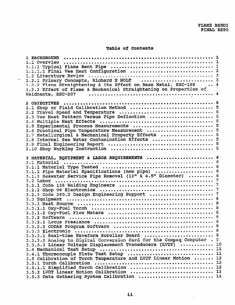
1.1.1 Typical Flame Bent PipeFor those panel members not familiar with flame bending pipe thefollowing sketches show some of the fundamentals.
P I P E L A Y E D O U T F O R V E E H E A T B E N D I N G
1
FLAME BENDINGFINAL REPORT
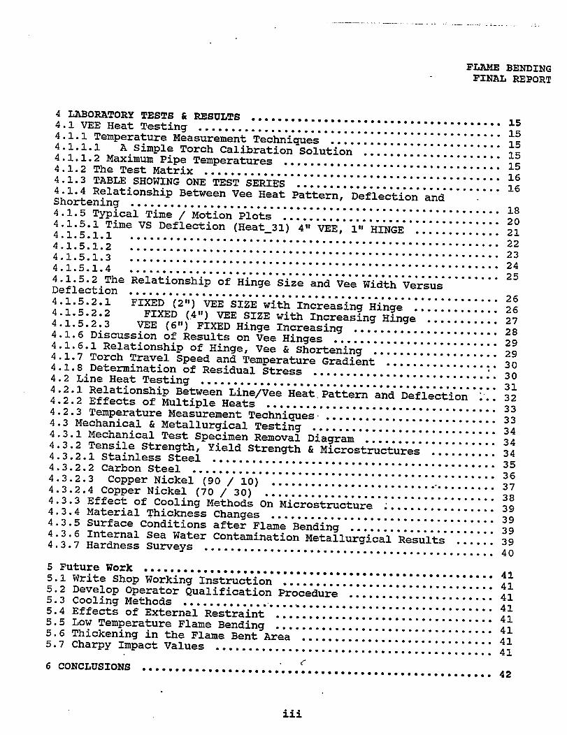
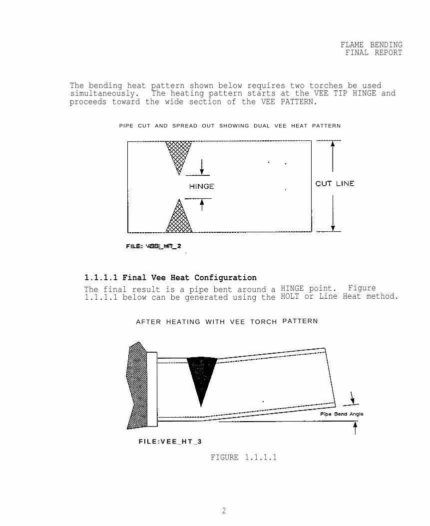
The bending heat pattern shown below requires two torches be usedsimultaneously. The heating pattern starts at the VEE TIP HINGE andproceeds toward the wide section of the VEE PATTERN.
PIPE CUT AND SPREAD OUT SHOWING DUAL VEE HEAT PATTERN
F I L E : V E E _ H T _ 2
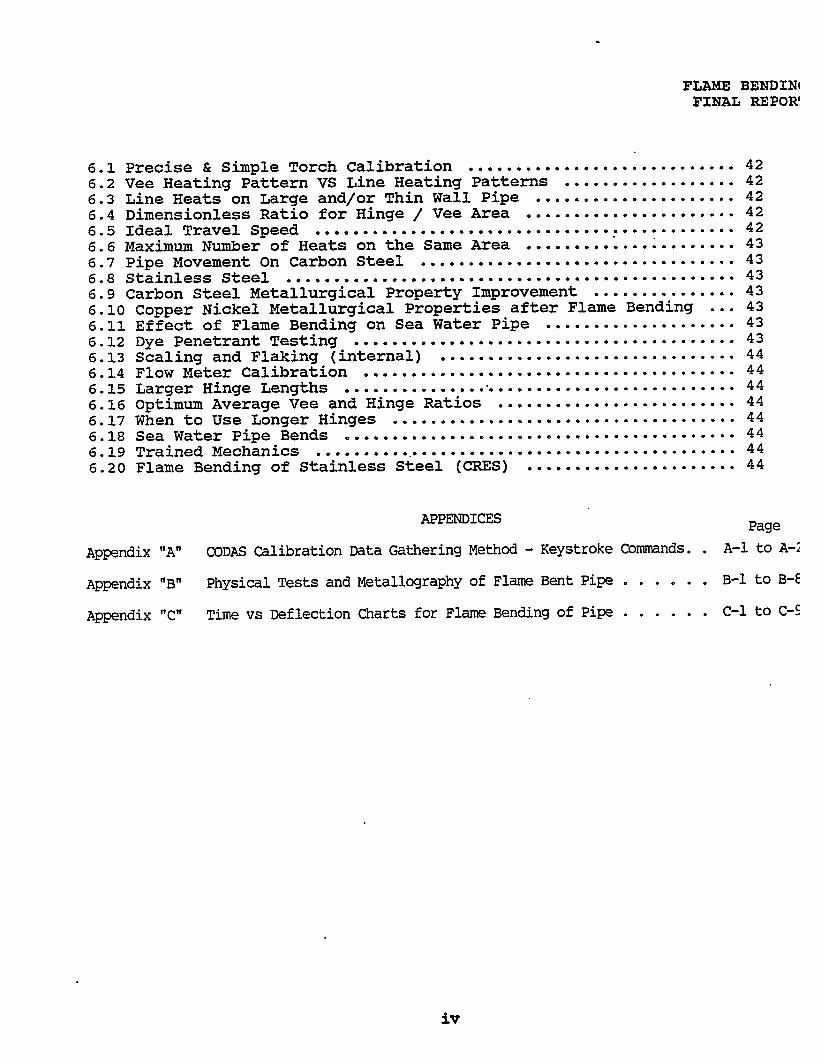
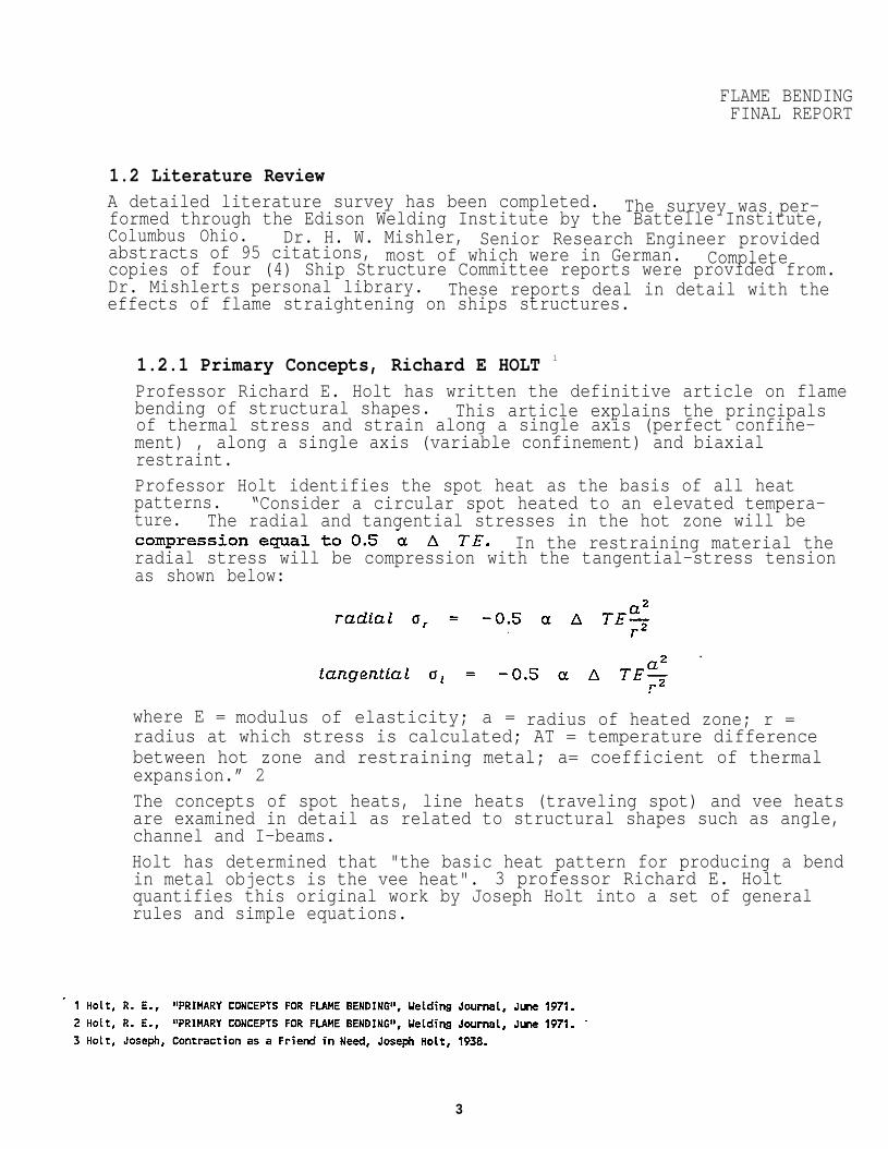
1.1.1.1 Final Vee Heat ConfigurationThe final result is a pipe bent around a1.1.1.1 below can be generated using the
AFTER HEATING WITH VEE TORCH
HINGE point. FigureHOLT or Line Heat method.
PATTERN
FlLE:VEE_HT_3
FIGURE 1.1.1.1
2
FLAME BENDINGFINAL REPORT
1.2 Literature ReviewA detailed literature survey has been completed. The survey was per-formed through the Edison Welding Institute by the Battelle Institute,Columbus Ohio. Dr. H. W. Mishler, Senior Research Engineer providedabstracts of 95 citations, most of which were in German. Completecopies of four (4) Ship Structure Committee reports were provided from.Dr. Mishlerts personal library. These reports deal in detail with theeffects of flame straightening on ships structures.
1.2.1 Primary Concepts, Richard E HOLT 1
Professor Richard E. Holt has written the definitive article on flamebending of structural shapes. This article explains the principalsof thermal stress and strain along a single axis (perfect confine-ment) , along a single axis (variable confinement) and biaxialrestraint.Professor Holt identifies the spot heat as the basis of all heatpatterns. “Consider a circular spot heated to an elevated tempera-ture. The radial and tangential stresses in the hot zone will be
In the restraining material theradial stress will be compression with the tangential-stress tensionas shown below:
where E = modulus of elasticity; a = radius of heated zone; r =radius at which stress is calculated; AT = temperature differencebetween hot zone and restraining metal; a= coefficient of thermalexpansion.” 2The concepts of spot heats, line heats (traveling spot) and vee heatsare examined in detail as related to structural shapes such as angle,channel and I-beams.Holt has determined that "the basic heat pattern for producing a bendin metal objects is the vee heat". 3 professor Richard E. Holtquantifies this original work by Joseph Holt into a set of generalrules and simple equations.
3
FLAME BENDINFINAL REPO
Mechanical properties of structural steels were shown to improveafter flame bending. Yield strengths were slightly above the origi-nal values and Ultimate tensile strengths showed slight reductions."Properly placed heat patterns produce a residual stress pattern thais lower in magnitude and more uniform than as-rolled material.Tests conducted by the US Army Corps of Engineers at Clear Alaska,showed the flame straightened A36 beams were superior to the asrolled beams.”
1.2.2 Flame Straightening & its Effect on Base Metal, SSC-198 5
This report is essentially a summary of literature and basic metal-lurgy associated with flame straightening on various classes of shipbuilding plate steels. This document lists 70 references.
1.2.3 Effect of Flame6& Mechanical Straightening on Properties ofWeldments, SSC-207This research covered various steel plate in the range from 40,000psi tensile to 100,000 psi tensile strength. One of the findingswas;
* “Buckling-type distortion decreases drastically as the platthickness increases, and it almost disappears when the plate thick-ness exceeds about 3/8"."Fracture transition temperatures were determined for ABS-2 type platin the as received and in the flame straightened condition. Flamestraightening temperatures were very close to the experimental tem-peratures of the PUGET SOUND NAVAL SHIPYARD work. Their temperaturewere 1300 to 1400 degrees F.As received ABS-2 plate have fracture transition temperatures of +52F. Flame straightened plate in this study had fracture transitiontemperatures of +70 F.Their conclusion was that "widespread use of flame straightening onABS-2 steel is an acceptable procedure”. The carbon steel pipe usedin the Naval Shipyards are very similar to ABS-2 grade steel.
4
FLAME BENDINGFINAL REPORT
2 OBJECTIVES
2.1 Shop or Field Calibration MethodTo Develop an accurate and simple method of calibrating the heat outputof the flame bending heat source.
2.2 Travel Speed and TemperatureTo determinegradient
2.3 Vee HeatTo determinetion.
2.4 MultipleTo determine
the relationship between torch travel speed and temperature
Pattern Versus Pipe Deflectionthe relationship between Vee heat pattern and pipe deflec-
Heat Effectsthe effectiveness of multiple heats.
2.5 Experimental Process MeasurementsTo determine a practical method of monitoring the heat distribution,using critical process parameters such as, torch travel speed, path,spot diameter and torch heat output.
2.6 Practical Pipe Temperature MeasurementTo investigate practical methods for measuring temperatures in processon the flame side, below red hot, for field applications.
2.7 Metallurgical & Mechanical Property Effects . To determine any detrimental effects of flame bending on the mechanicalproperties and metallurgical structure of various alloys.
2.8 Internal Sea Water Contamination EffectsTo determine any detrimental effects of flame bending on pipe with ser-vice related internal contamination.
2.9 Final Engineering ReportTo write a detailed final engineering report.
2.10 Shop Working InstructionTo develop a practical shop working instructiontion shop floor.
for use on the produc-
5
FLAME BENDINGFINAL REPORT
3 MATERIAL, EQUIPMENT & LABOR REQUIREMENTSThe primary purpose of this section is to describe in detail the experimen-tal setup, material, equipment and recording devices used to achieve thefinal results.
3.1 Material
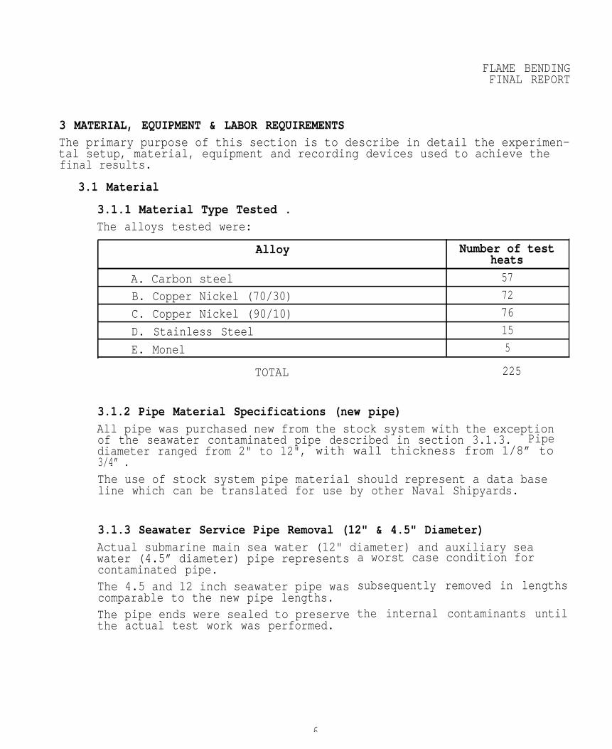
3.1.1 Material Type Tested .The alloys tested were:
Alloy Number of testheats
A. Carbon steel 57
B. Copper Nickel (70/30) 72
C. Copper Nickel (90/10) 76
D. Stainless Steel 15
E. Monel 5
TOTAL 225
3.1.2 Pipe Material Specifications (new pipe)All pipe was purchased new from the stock system with the exceptionof the seawater contaminated pipe described in section 3.1.3. Pipediameter ranged from 2" to 12", with wall thickness from 1/8” to 3/4” .The use of stock system pipe material should represent a data baseline which can be translated for use by other Naval Shipyards.
3.1.3 Seawater Service Pipe Removal (12" & 4.5" Diameter)Actual submarine main sea water (12" diameter) and auxiliary seawater (4.5” diameter) pipe representscontaminated pipe.The 4.5 and 12 inch seawater pipe wascomparable to the new pipe lengths.Thethe
pipe ends were sealed to preserveactual test work was performed.
a worst case condition for
subsequently removed in lengths
the internal contaminants until
6
FLAME BENDINGFINAL REPORT
3.2 Labor
3.2.1 Code 138 Welding EngineersAll hands on lab work was performed by J. Dwight, Mr. Dale Heagy, Mr.Steve Nelson and Mr. Bob Houghteling. Mr. Derek Mortvedt assistedduring certain phases of the work and was especially helpful on finalreview of results.
Mr. Frank Gatto was the Project Manager and provided detail technicalguidance.Mr Steve Nelson and J. Dwight shared Project Engineer responsibili-ties.Mr. Douglas Coglizer provided financial and technical guidance forthe entire program.
3.2.2 Shop 06 ElectronicsMr. Tony D' Andrea of Shop 67 performed all electronic support work.Mr. D'Andrea performed all installation and setup of analog to digi-tal conversion boards and performed the initial calibrations ofLVDT ' S .
3.2.3 Code 260.2 Design Engineering SupportCode 260.2, Design Engineering, wrote a detail instruction to have4.5 and 12 inch diameter Main Seawater Copper Nickel (70-30) piperemoved from a submarine. They selected EX-SSN618 which has been service for approximately 20 years.
Code 260.2 personnel have been helpful and maintained an interest ithe flame bending study throughout the program.
7
FLAME BENDIFINAL REPO
3.3 Equipment
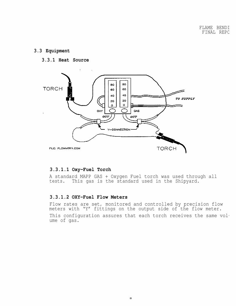
3.3.1 Heat Source
3.3.1.1 Oxy-Fuel TorchA standard MAPP GAS + Oxygen Fuel torch was used through alltests. This gas is the standard used in the Shipyard.
3.3.1.2 OXY-Fuel Flow MetersFlow rates are set, monitored and controlled by precision flowmeters with “Y” fittings on the output side of the flow meter.This configuration assures that each torch receives the same vol-ume of gas.
8
FLAME BENDINGFINAL REPORT
3.3.2 Software
3.3.2.1 Lotus FreelanceLotus "Freelance" was used to place all drawings directly into theword processing program.
3.3.2.2 CODAS Program SoftWare Analog to digital data conversions of pipe motion3 axis. The data was manipulated using the CODAS
was recorded insoftware. The
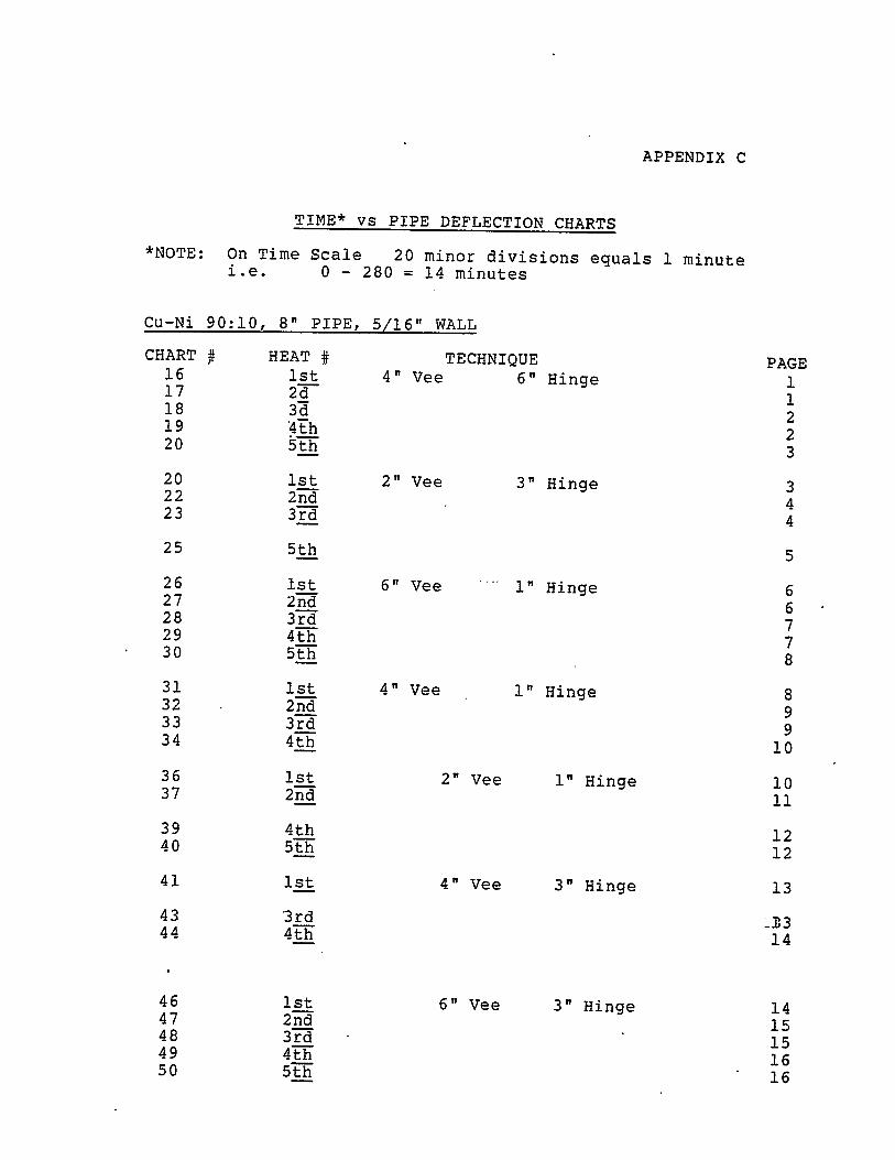
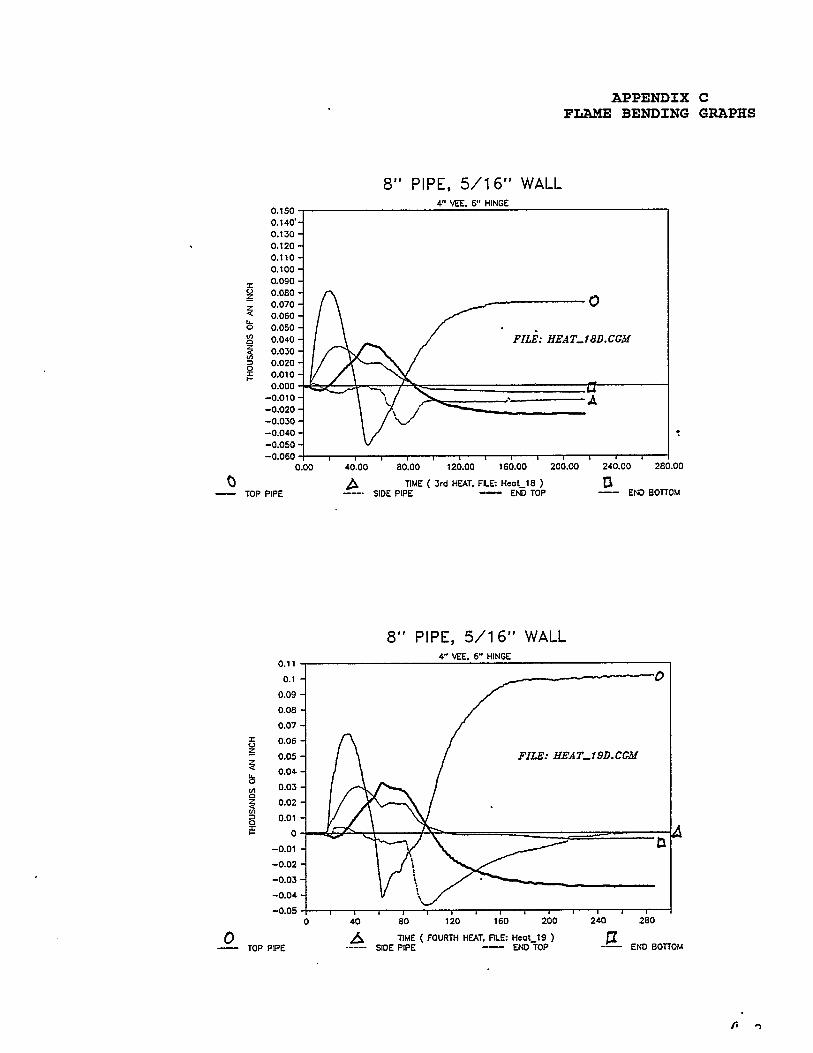
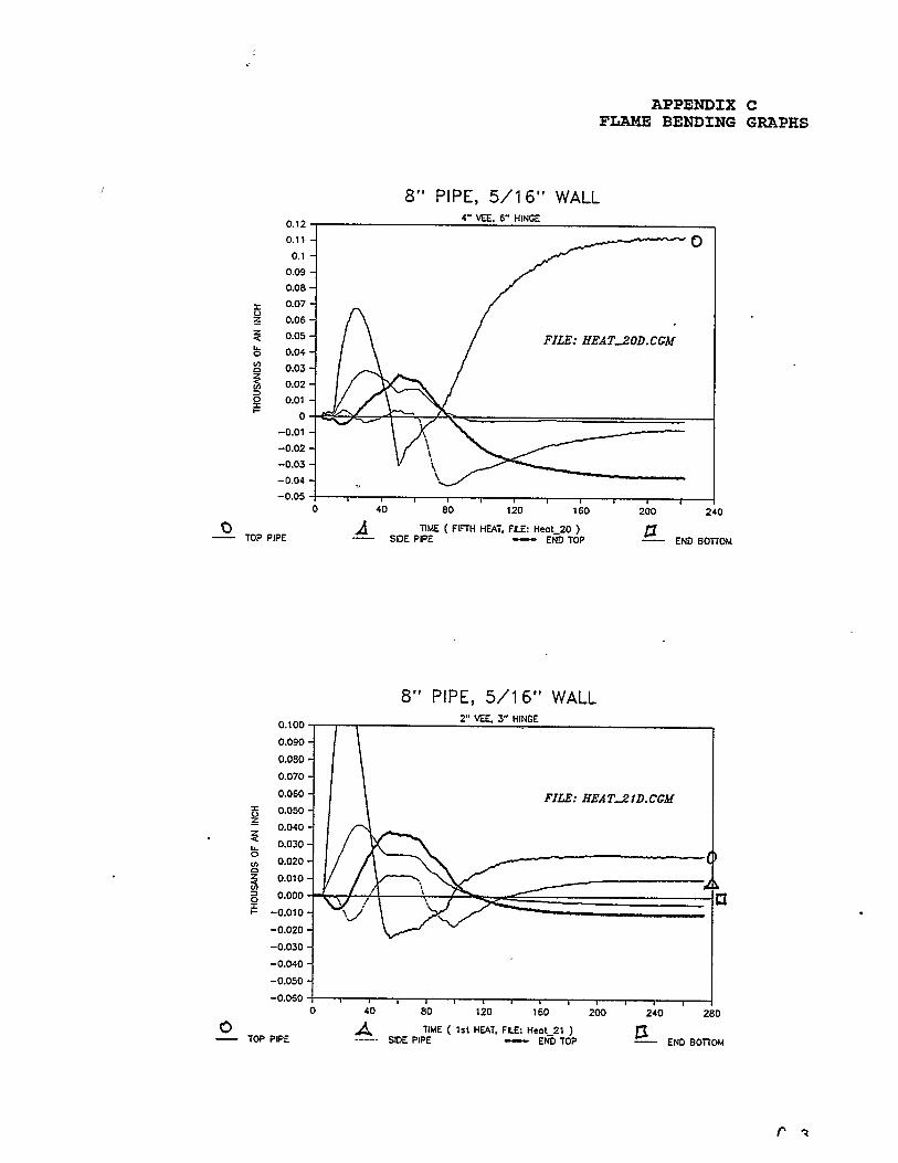
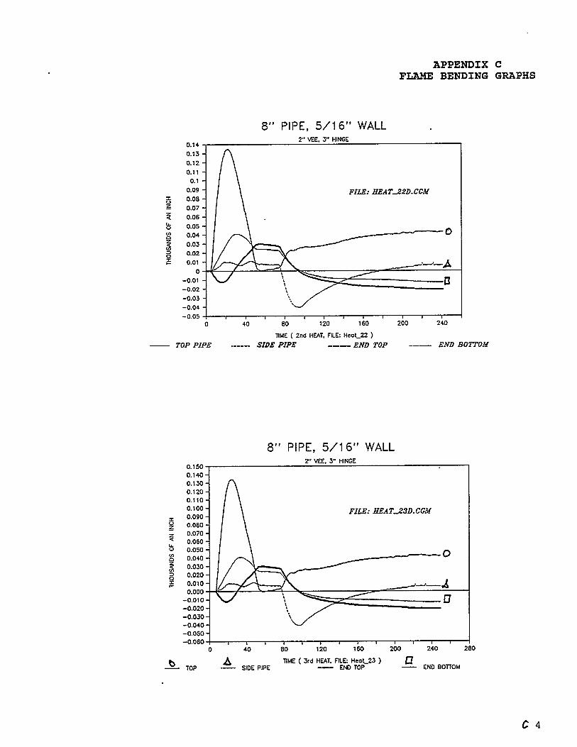
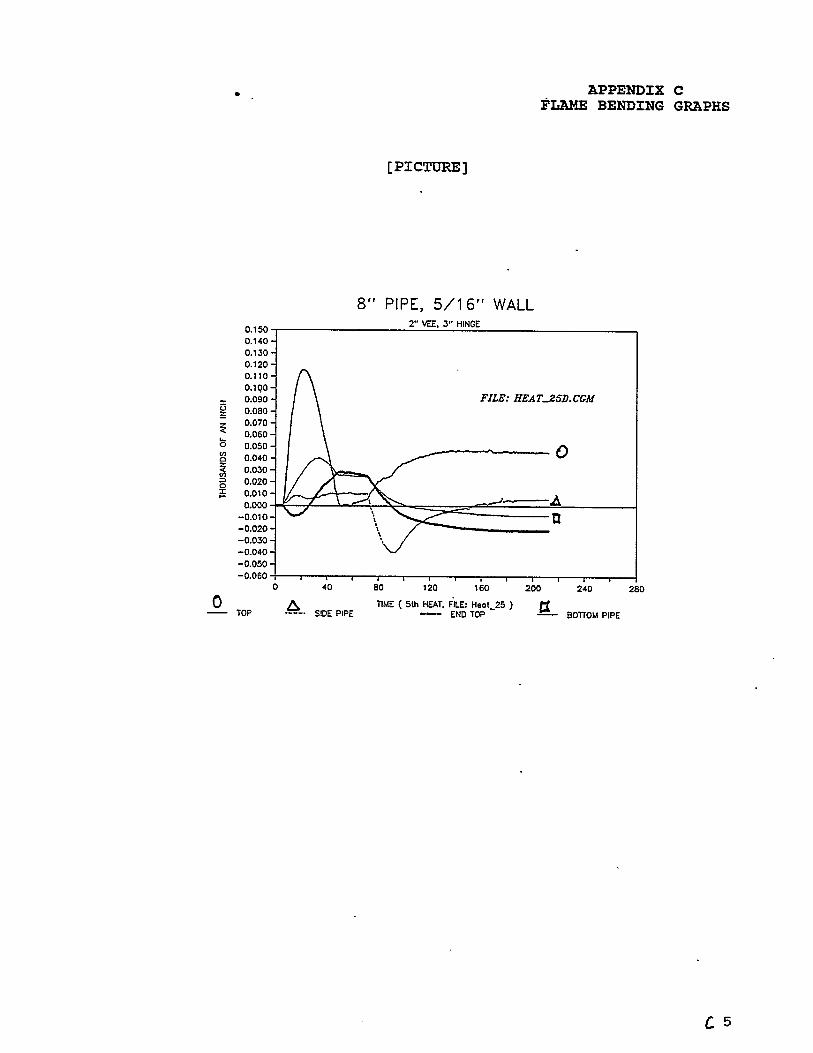
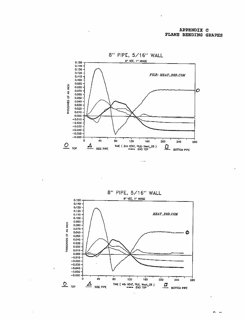
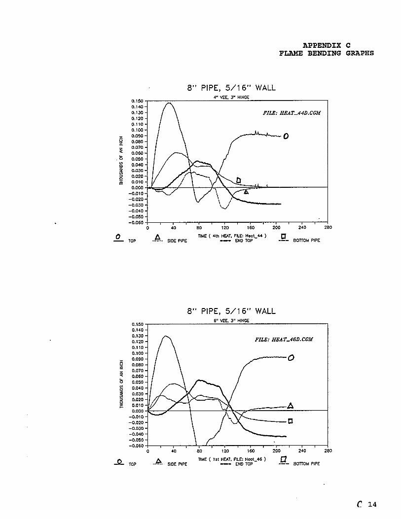
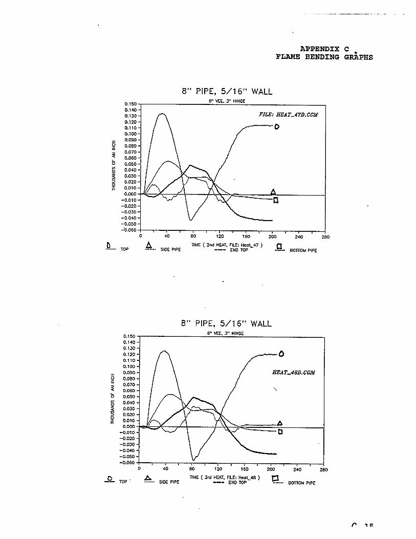
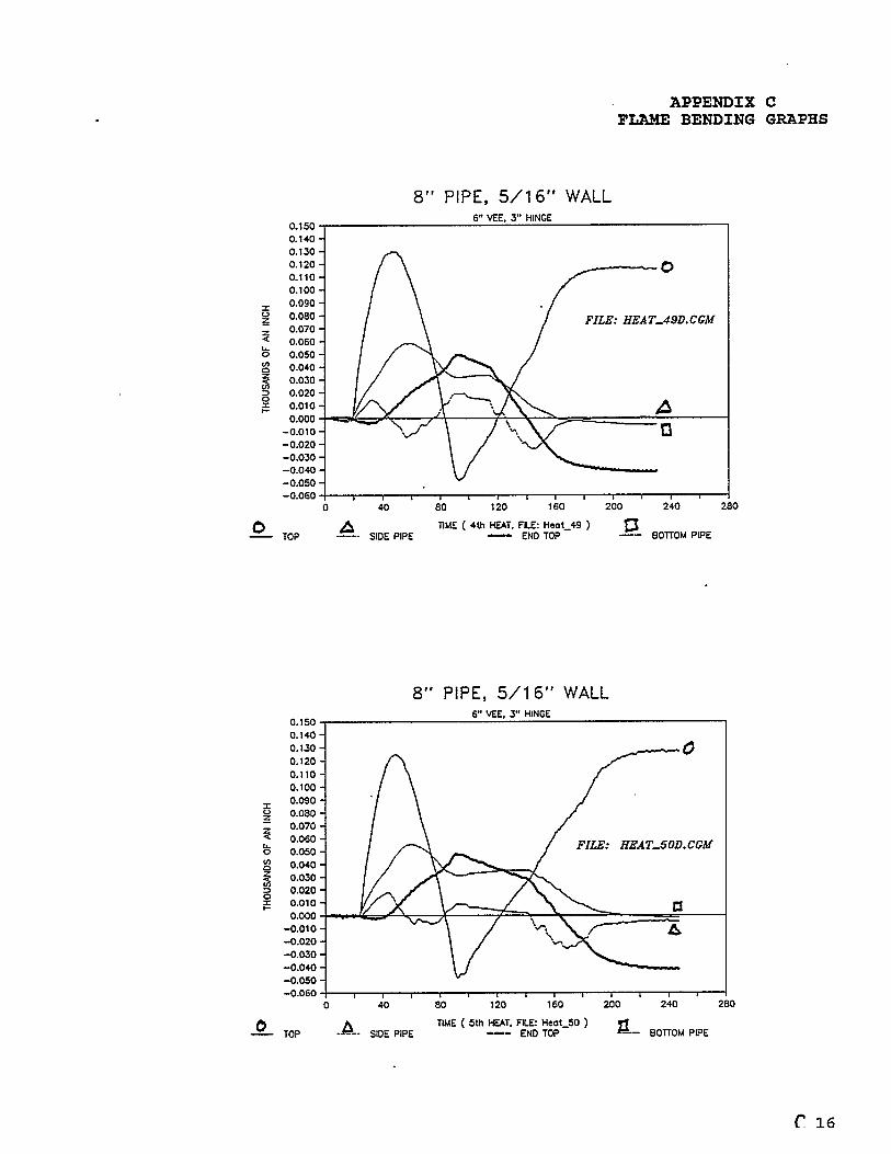
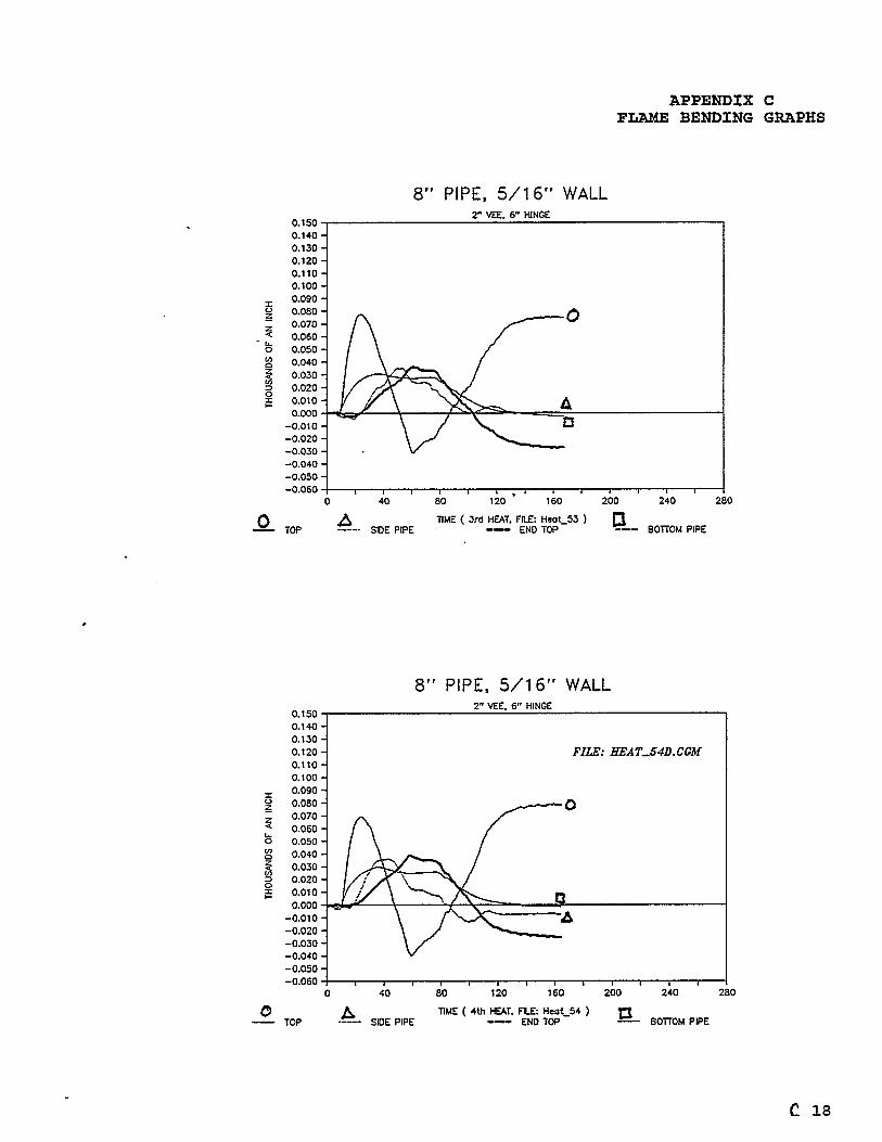
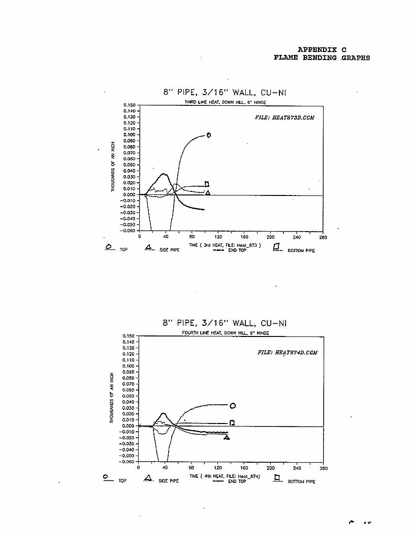
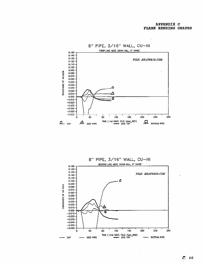
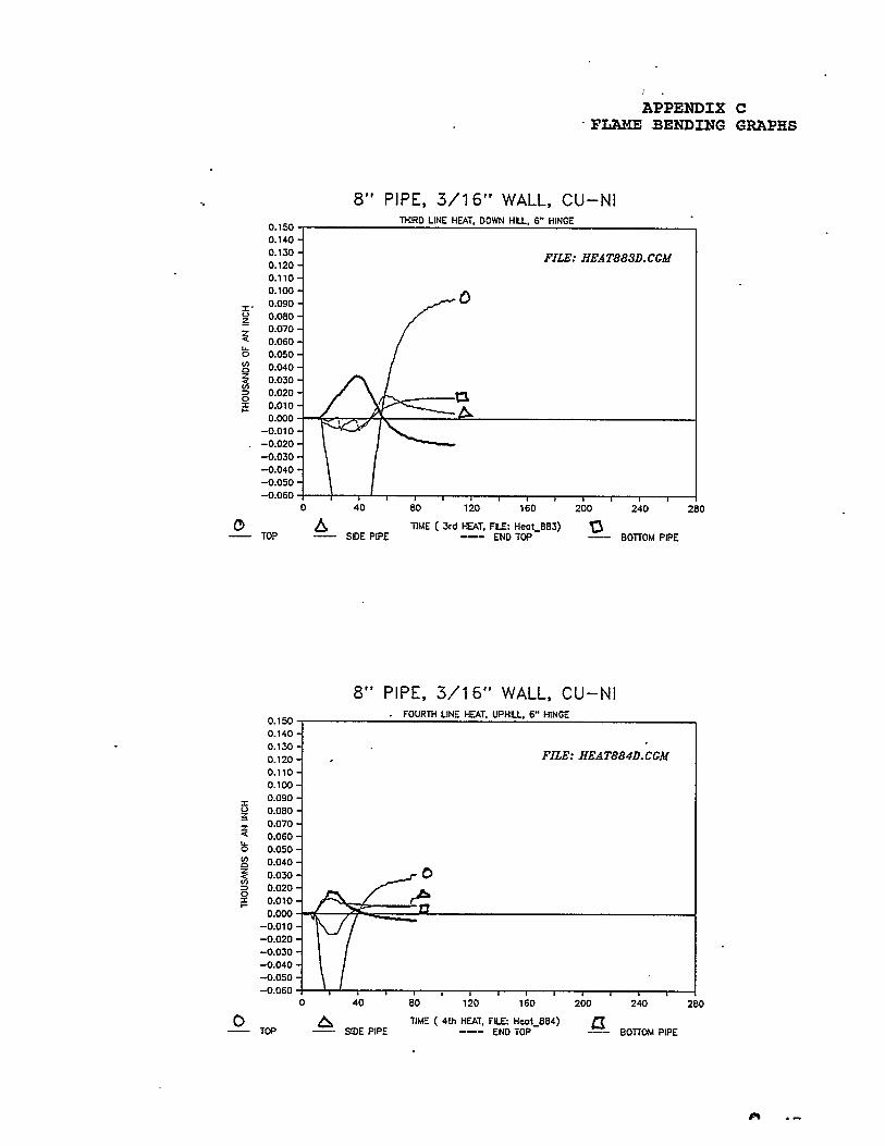
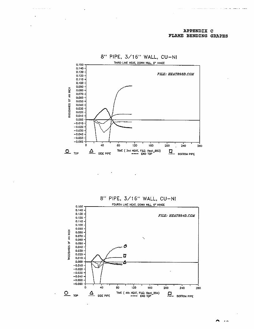
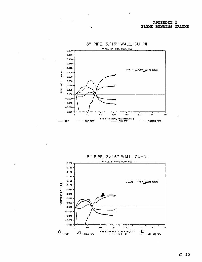
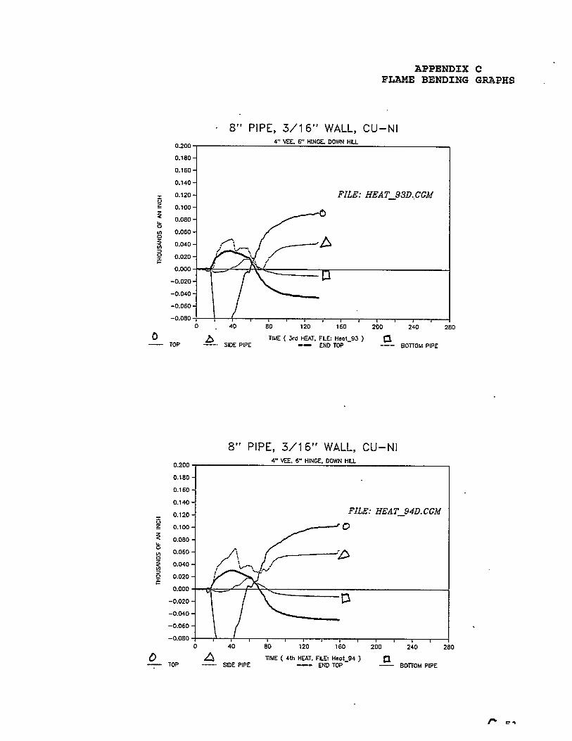
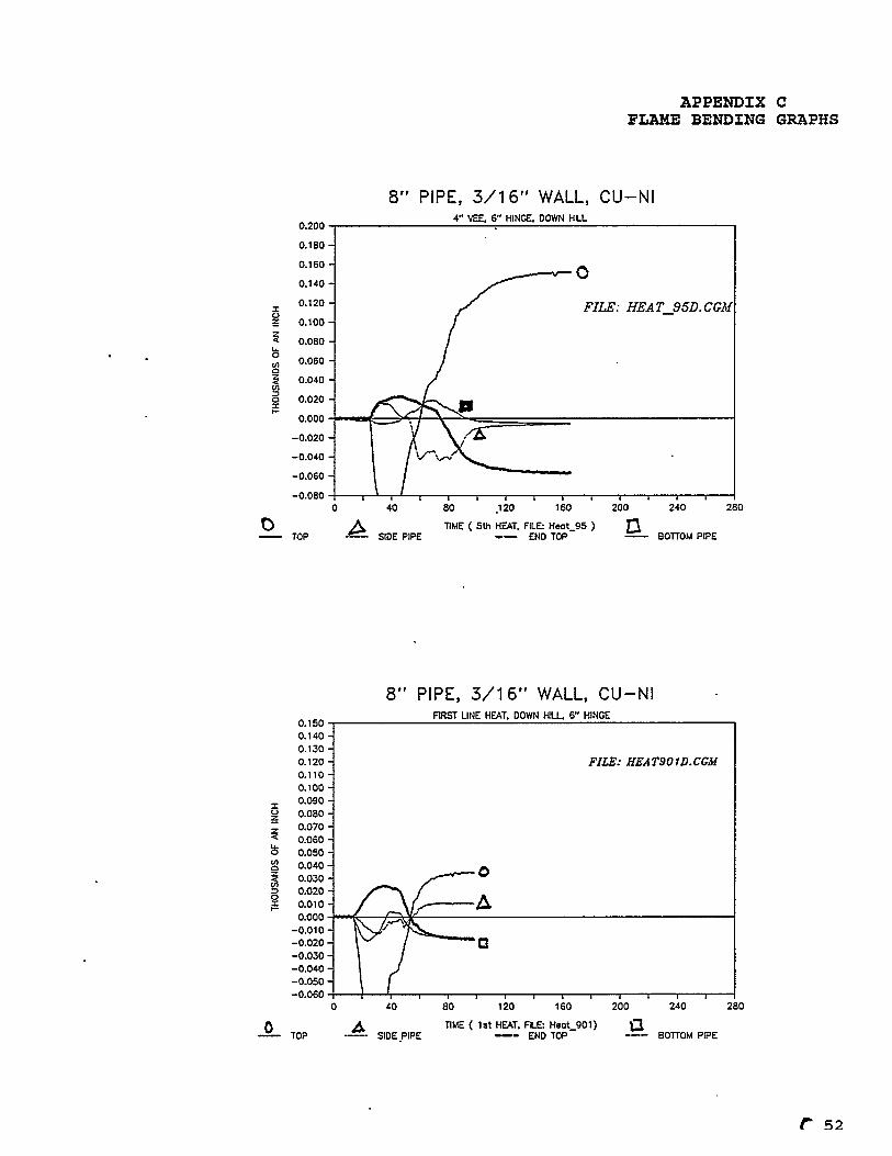
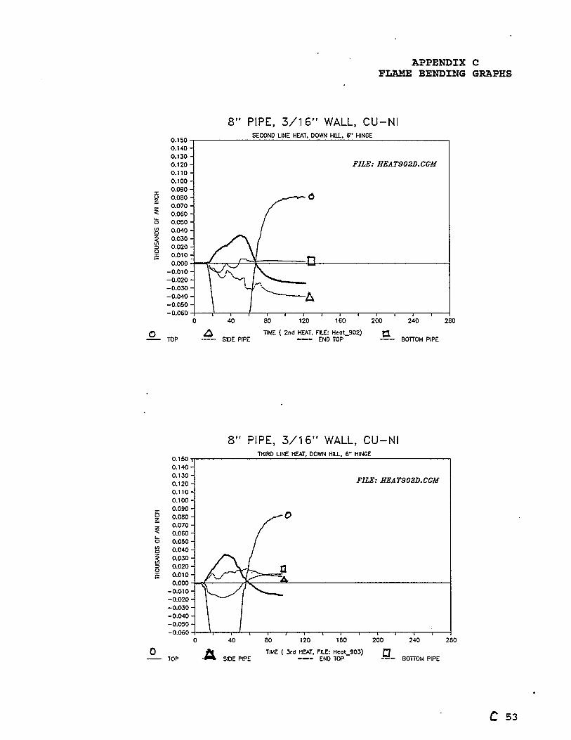
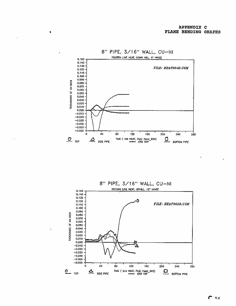
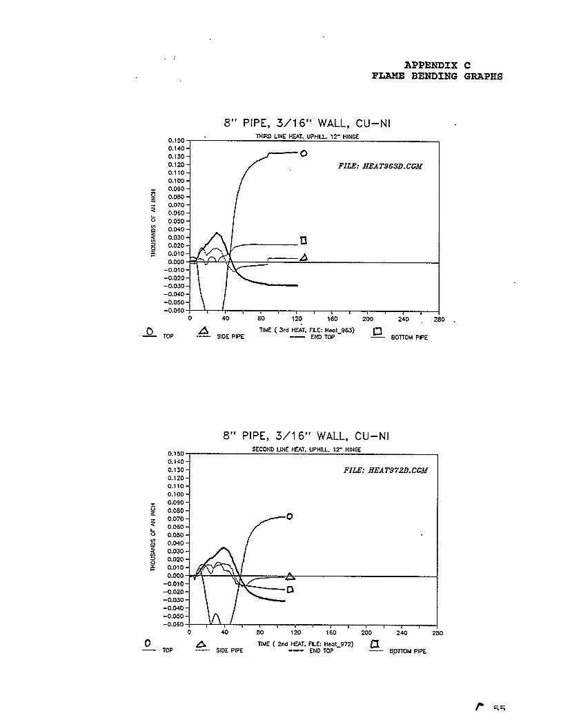
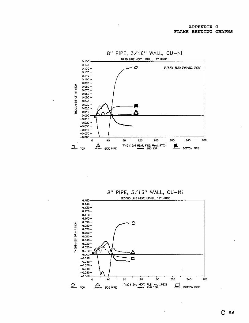
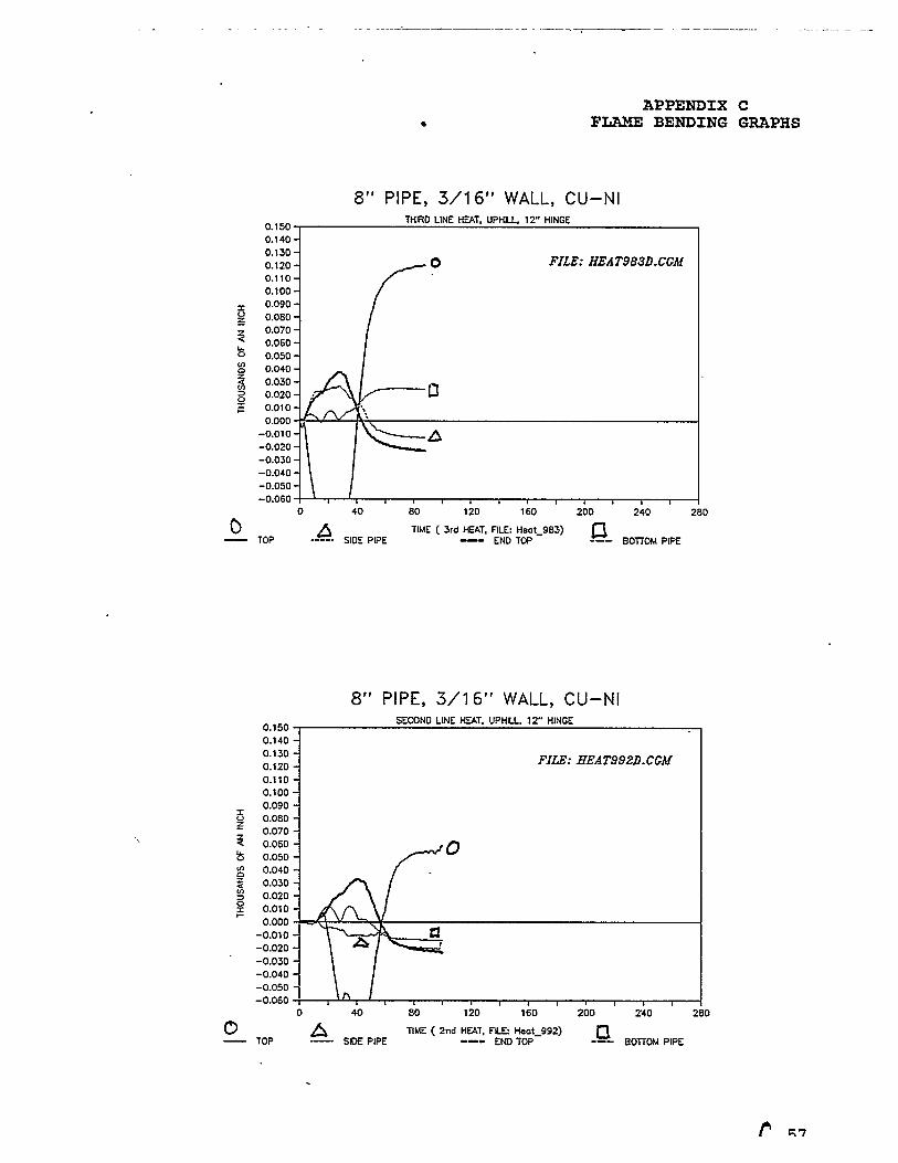
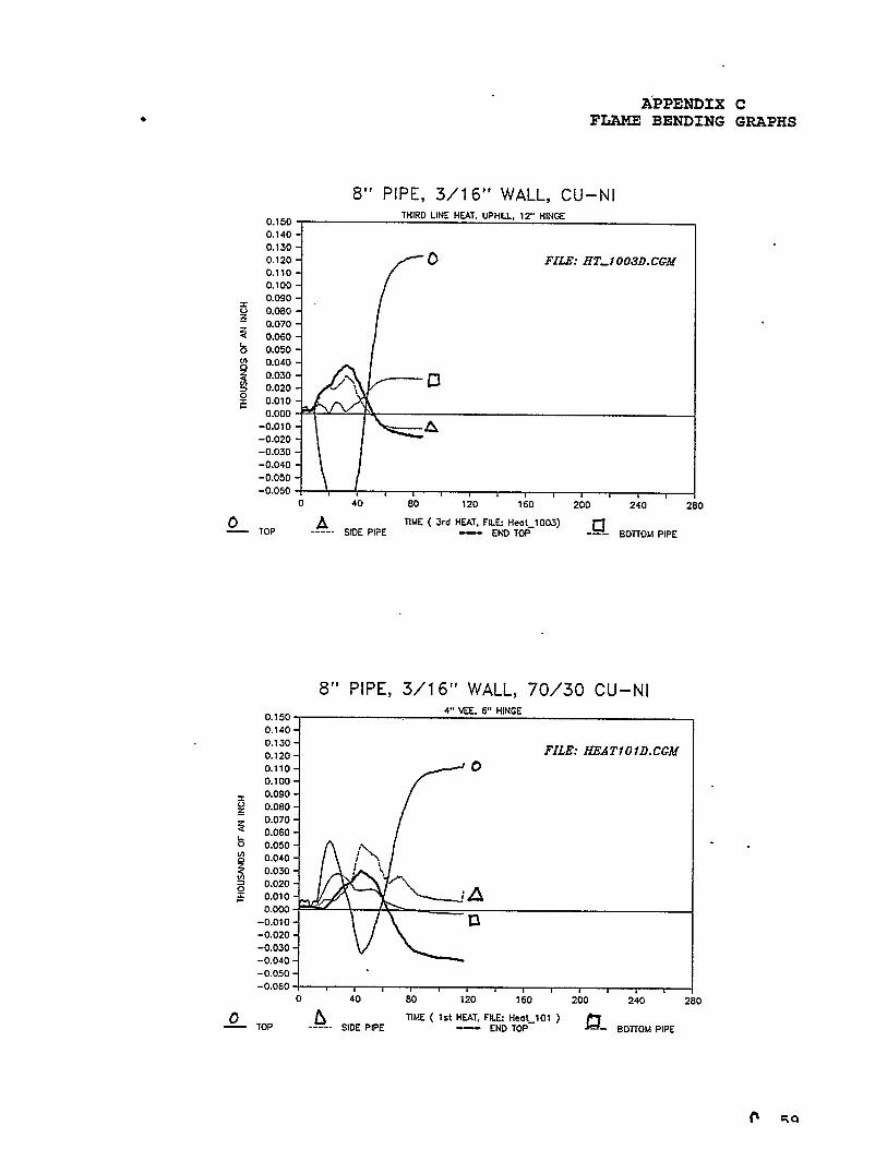
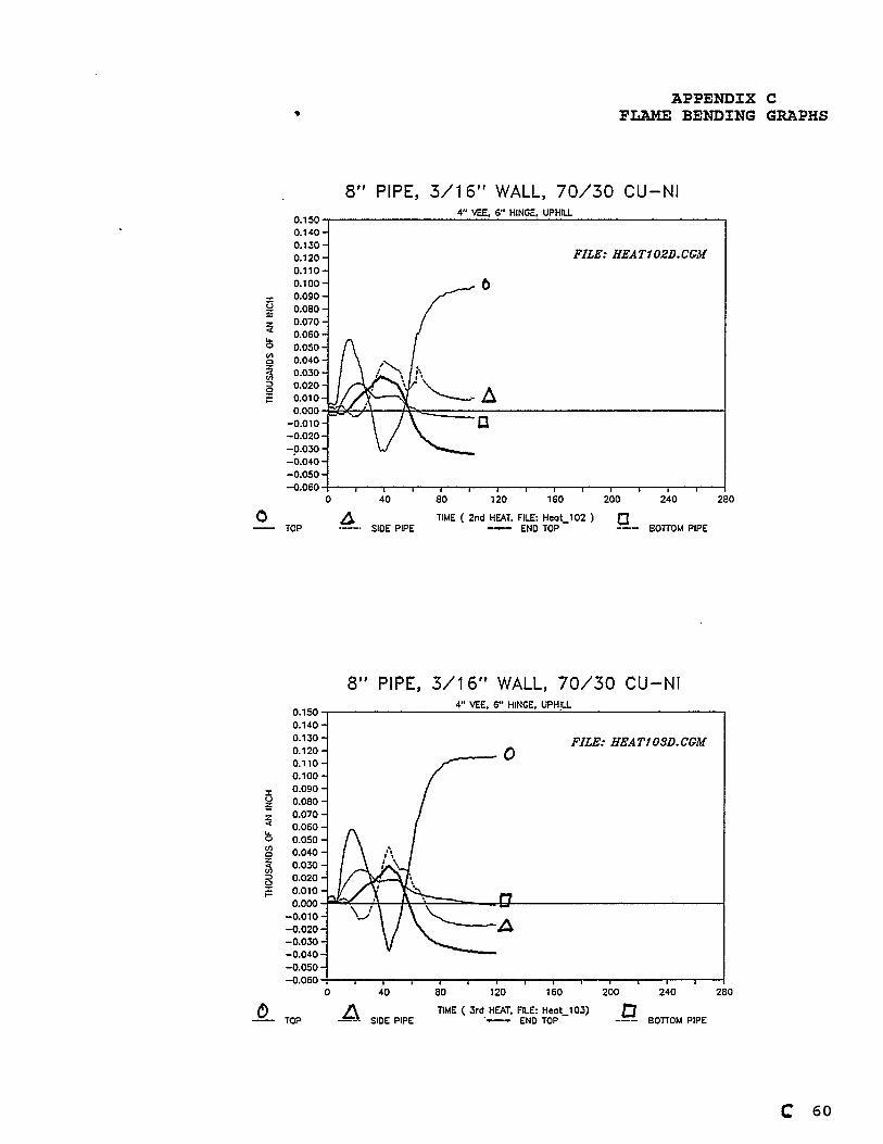
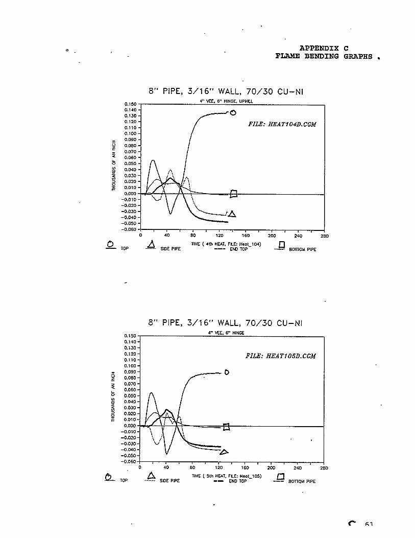
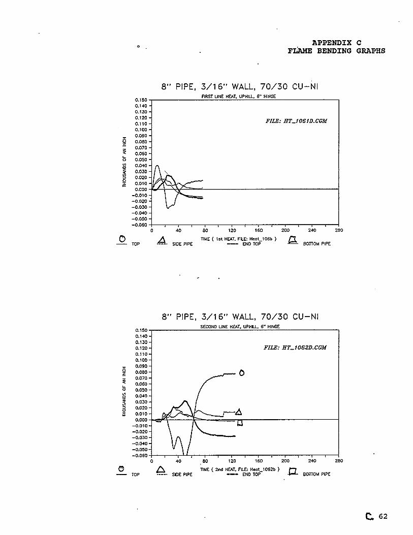
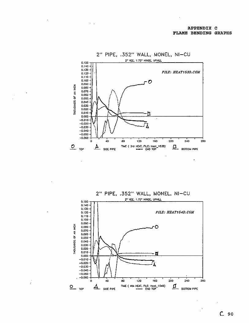
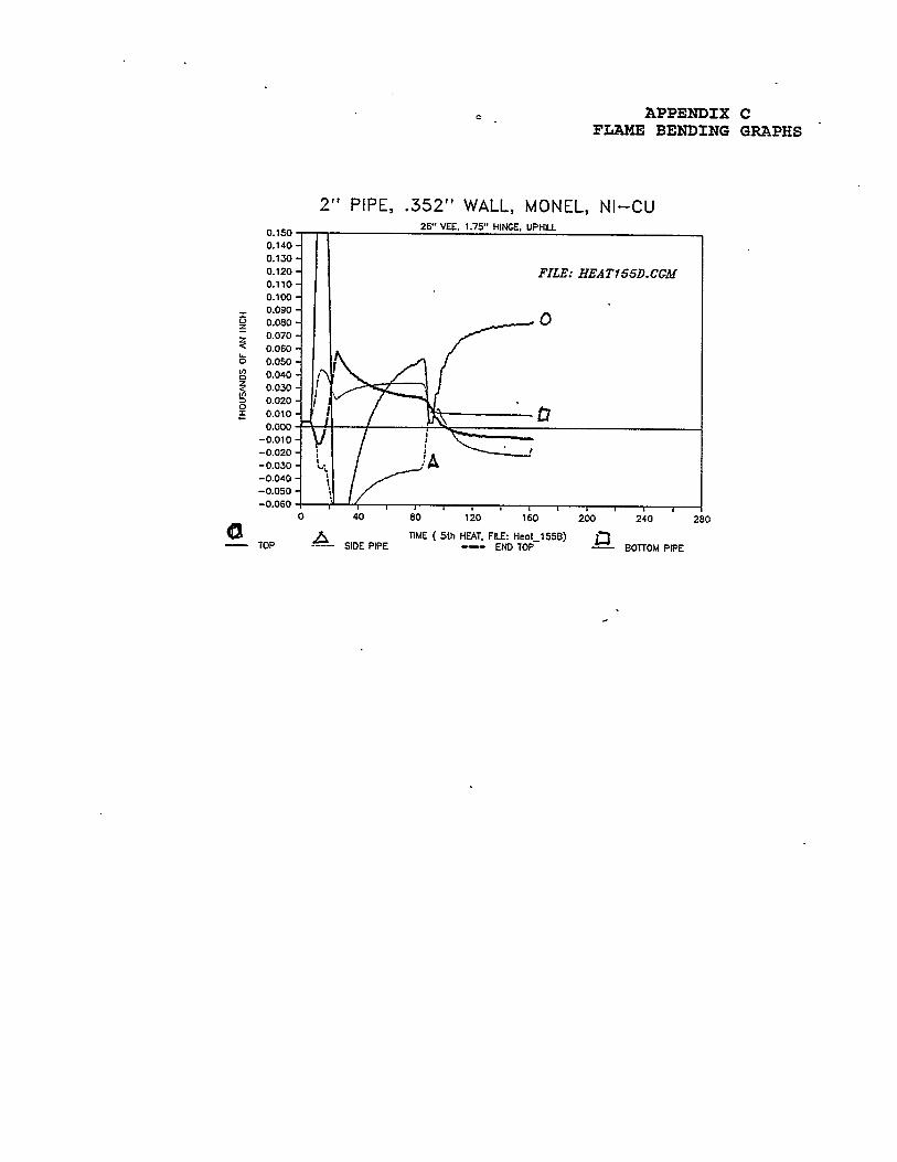
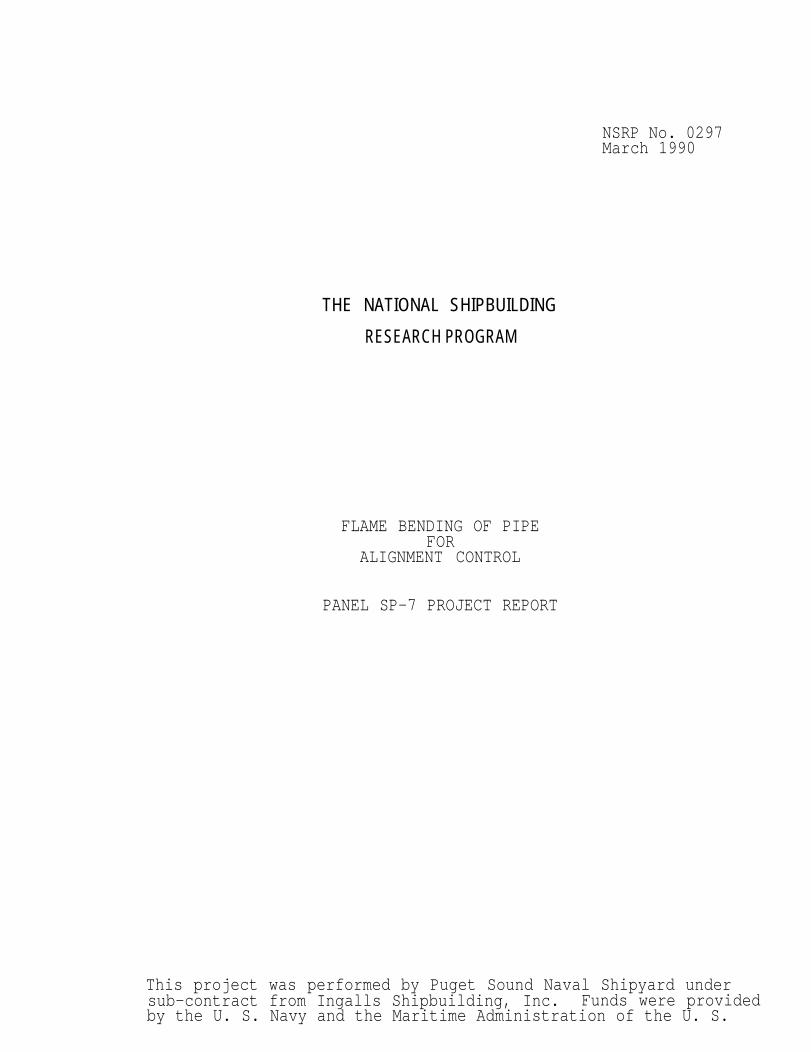
results of these real time records were fed into lotus 1,2,3for graph generation.The finish graphs are contained in -- appendix C.
3.3.3 .Electronic
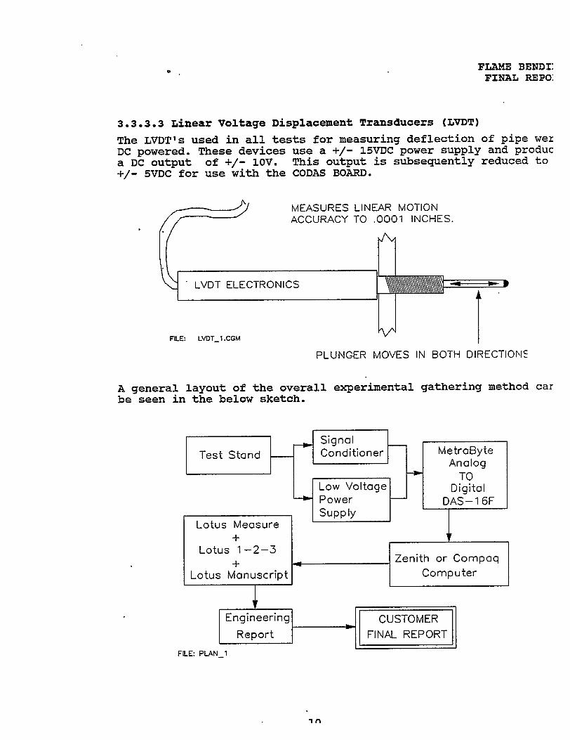
3.3.3.3 Real-time Waveform Scroller BoardThe CODAS WFS-200 card was used to display the data in real time.as it was gathered. This card works with the METRA BYTE EXP-16A-D conversion card (see section 3.3.3.2)Pipe movement was recorded as each experiment proceeded. The datawas real time on the computer screen with up to 8 windows visibleat one time.The CODAS real-time waveform scroller has software that allows theuser to display data at different rates. The user can also lookat very small segments of the data if required.The CODAS circuit card and software eliminates the requirement forthe user to write programs. Programming is required if the METRABYTE EXP-16 is used with out support hard/software.
3.3.3.2 Analog to Digital Conversion Card for the Compaq ComputerThe METRA BYTE EXP-16 card was installed and used in conjunctionwith the real time waveform scroller board.The function of this board is to convert the low voltage DC sig-nals from various transducers such as LVDT’S and thermocouples todigital signals which the computer can process.
9
FLAME BENDINGFINAL REPORT
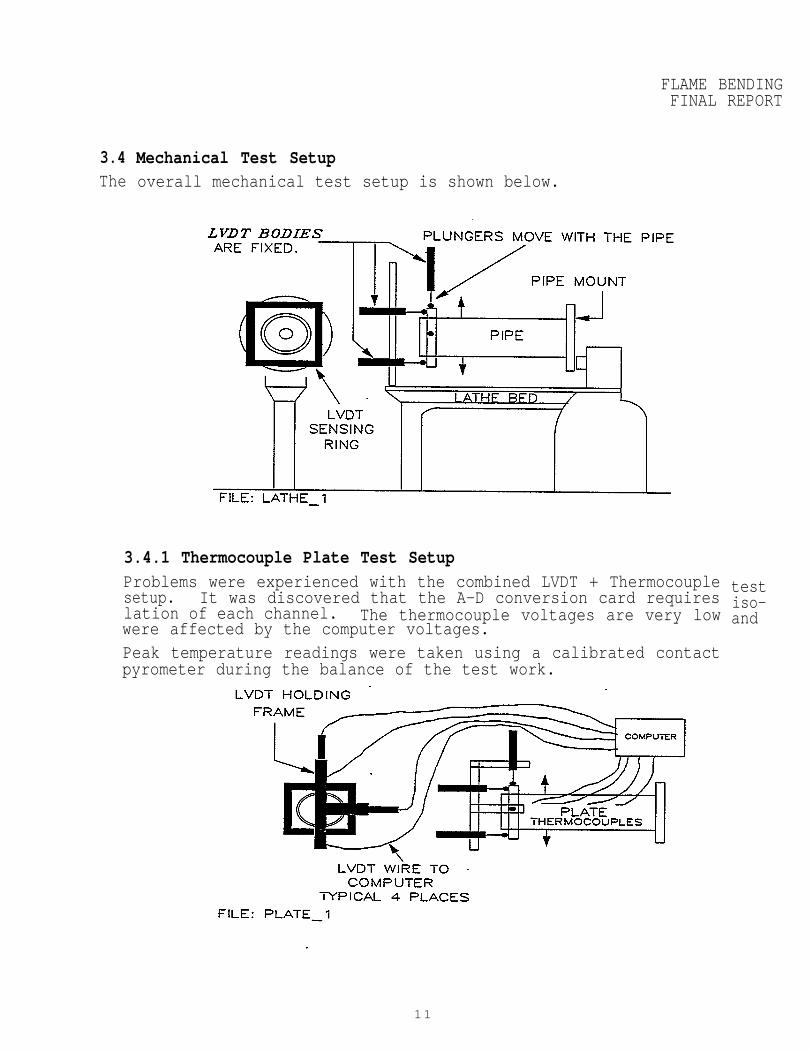
3.4The
Mechanical Test Setupoverall mechanical test setup is shown below.
3.4.1 Thermocouple Plate Test SetupProblems were experienced with the combined LVDT + Thermocouplesetup. It was discovered that the A-D conversion card requireslation of each channel. The thermocouple voltages are very lowwere affected by the computer voltages.Peak temperature readings were taken using a calibrated contactpyrometer during the balance of the test work.
testiso-and
11
FLAME BENDINGFINAL REPORT
3.5 Calibration of Torch TemperatureThe calibration of torch temperatureperformed using the following detail
3.5.1 Torch Calibration
and LVDT Linear Motionoutput and LVDT’S linear motion wasprocedures.
Various methods of torch calibration were tried including thermalcouples attached to pipe, plate and pipe rings. The vee heats wereapplied and the record of time/temperature was recorded. Theseresults were then plotted using lotus 123.These methods of torch calibration using automatic data gatheringwere too complex and the results were difficult to translate into aproduction procedure.
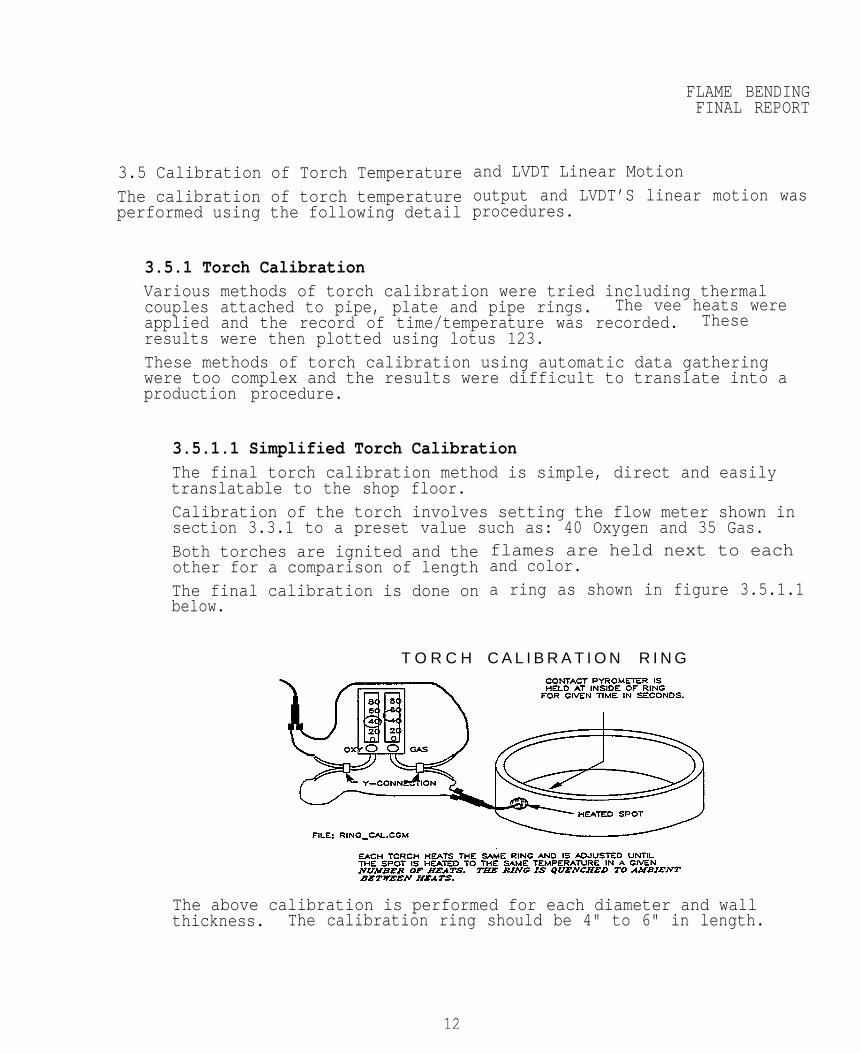
3.5.1.1 Simplified Torch CalibrationThe final torch calibration method is simple, direct and easilytranslatable to the shop floor.Calibration of the torch involves setting the flow meter shown insection 3.3.1 to a preset value such as: 40 Oxygen and 35 Gas.Both torches are ignited and theother for a comparison of lengthThe final calibration is done onbelow.
T O R C H
flames are held next to eachand color.a ring as shown in figure 3.5.1.1
C A L I B R A T I O N R I N G
The above calibration is performed for each diameter and wallthickness. The calibration ring should be 4" to 6" in length.
12
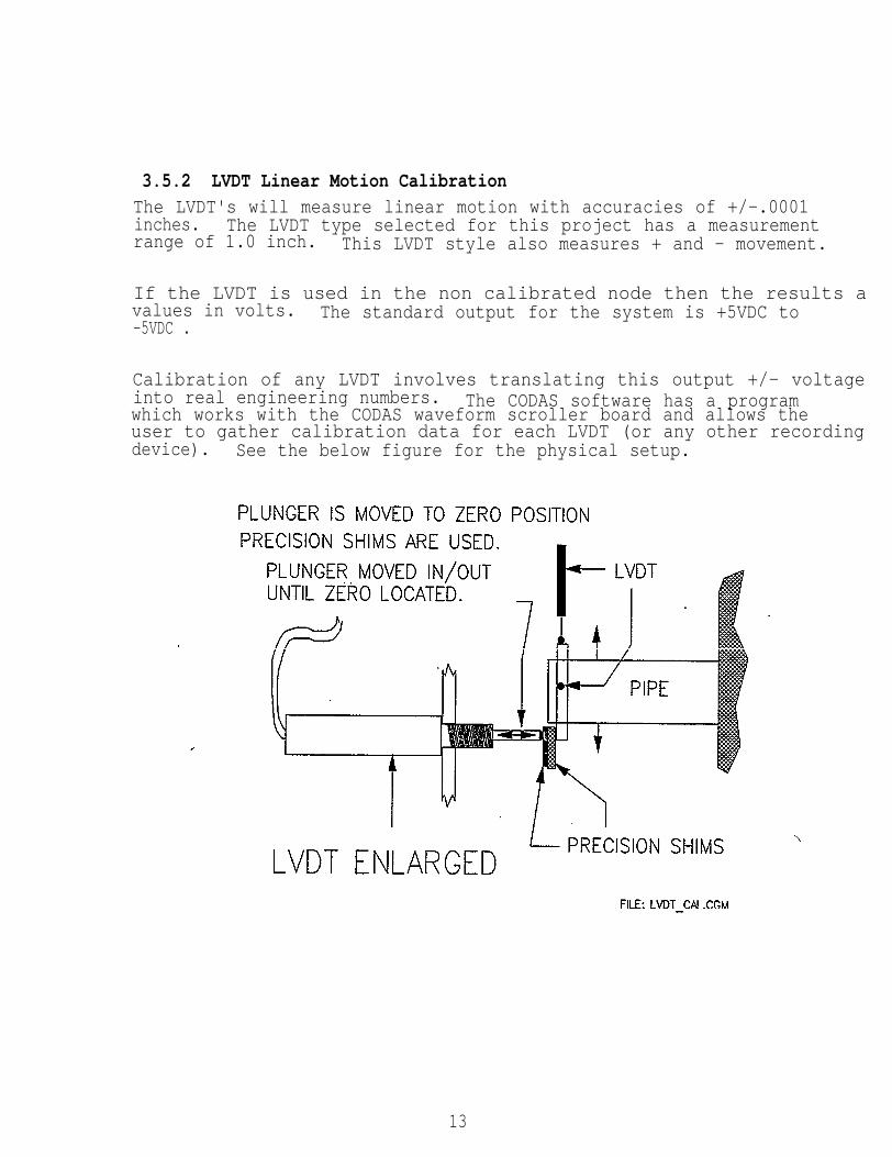
3.5.2 LVDT Linear Motion CalibrationThe LVDT's will measure linear motion with accuracies of +/-.0001inches. The LVDT type selected for this project has a measurementrange of 1.0 inch. This LVDT style also measures + and - movement.
If the LVDT is used in the non calibrated node then the results avalues in volts. The standard output for the system is +5VDC to-5VDC .
Calibration of any LVDT involves translating this output +/- voltage into real engineering numbers. The CODAS software has a programwhich works with the CODAS waveform scroller board and allows theuser to gather calibration data for each LVDT (or any other recording device). See the below figure for the physical setup.
13
FLAME BENDINFINAL REPOR
Calibration. is accomplished as follows.* The LVDT (one LVDT per channel) is adjusted to zero on thecomputer screen.
* A small segment of voltage is recorded at Zero.
* The LVDT is repositioned to some given value. In our case aprecision shim of .0925 inches thickness was used. This results in positive voltage. A small segment of voltage is recorded at thispositive value.
* The LVDT is again repositioned to a negative value using theprecision shims. A final small segment of voltage is recorded atthis negative value.
We now have three (3) voltage readings for one LVDT channel.
* The final step is to run the program called CODAS POSTACQ whichallows the voltage readings to be converted to engineering units.This small computer file is identified by a unique name such asHEAT_XX.CAL. -
when data is gathered in a test the HEAT_XX.CAL file is Present andsets all test-data with theHEAT_XX.CAL file eliminated
3.5.3 Data Gathering System
engineering units you defined. Thetime consuming arithmetic errors.
Calibration
The Key Stroke instruction detailed in APPENDIX B was used throughoucalibration.APPENDIX B can be used as a detail instruction in lieu of reading thCODAS POSTACQ instruction manual.
14
4 LABORATORY TESTS & RESULTSThe experimental work was conductedfacility.
4.1 VEE Heat Testing
4.1.1 TemperatureA primary problem
Measurement
FLAME BENDINGFINAL REPORT
in the Code 138 Welding Laboratory
Techniquesfor flame bending is the accurate measurement of
heat input and the maximum temperature reached during flame bending.
4.1.1.1 A Simple Torch Calibration SolutionThe torch calibration procedure has been previously described insection 3.5.1 . A satisfactory torch calibration was consideredto be when both torches heated the same spot within +/- 25° F at agiven time in seconds.
The most efficient time at temperature for all 225 tests was 850°F in 15 seconds.The standard time at temperature was derived by experimentation.The low temperature tested was 850° F in 10 seconds and the hightemperature input tested was 1000° F in 15 seconds. The standardwas selected as 850° F in 15 seconds.Each pipe diameter, wall thickness and material type was testedusing the 850° F in 25 second standard calibration.
4.1.1.2 Maximum Pipe TemperaturesConsiderable concern was expressed abouttemperature on the chemical and physical material.
Maximum pipe temperatures were measuredon the top hot spot after completion ofthe maximum temperature was recorded on
the effects of maximum -properties of the pipe
using a contact pyrometereach heat. A record ofthe heat work record.
15
FLAME BENDIFINAL REPO
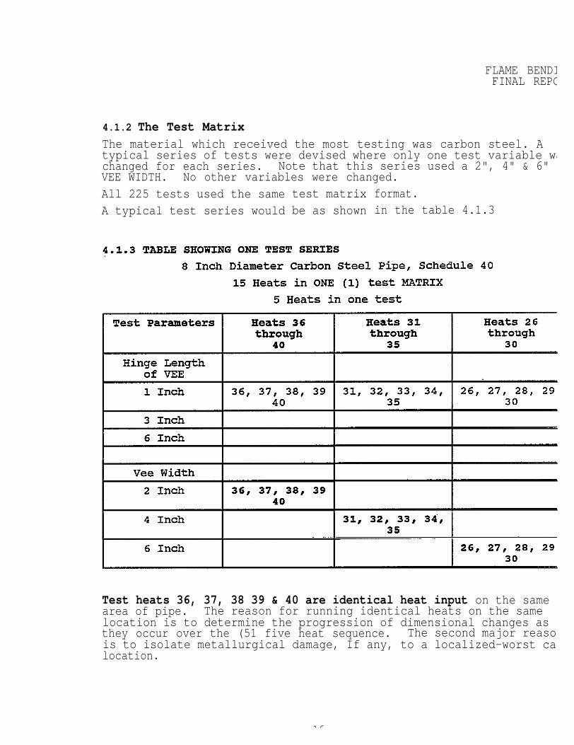
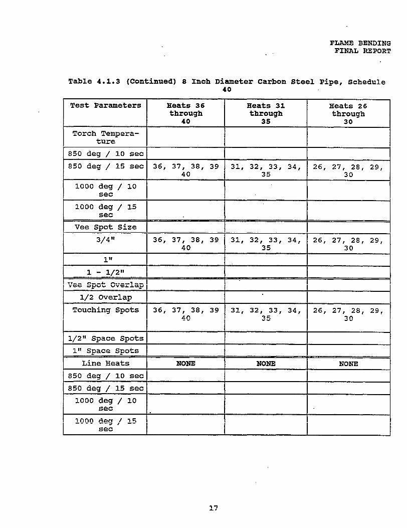
4.1.2 The Test MatrixThe material which received the most testing was carbon steel. Atypical series of tests were devised where only one test variable wachanged for each series. Note that this series used a 2", 4" & 6"VEE WIDTH. No other variables were changed.All 225 tests used the sameA typical test series would
test matrixbe as shown
format.in the table 4.1.3
Test heats 36, 37, 38 39 & 40 are identical heat input on the samearea of pipe. The reason for running identical heats on the samelocation is to determine the progression of dimensional changes asthey occur over the (51 five heat sequence. The second major reasonis to isolate metallurgical damage, If any, to a localized-worst caslocation.
16
FIAME BENDIFINAL REPO
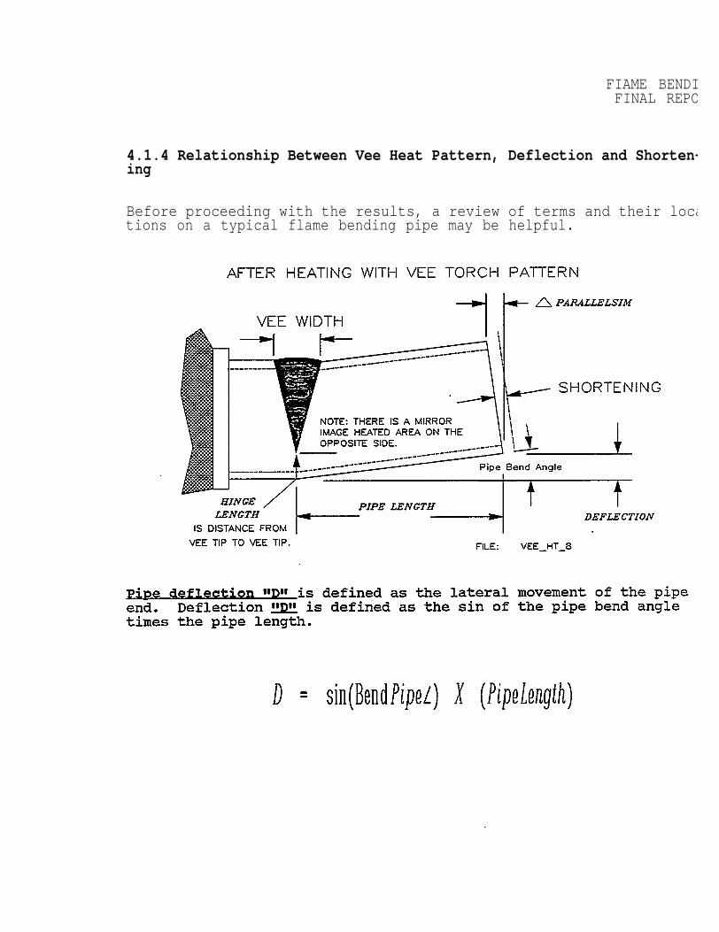
4.1.4 Relationship Between Vee Heat Pattern, Deflection and Shorten-ing
Before proceeding with the results, a review of terms and their locations on a typical flame bending pipe may be helpful.
FLAME BENDINGFINAL REPORT
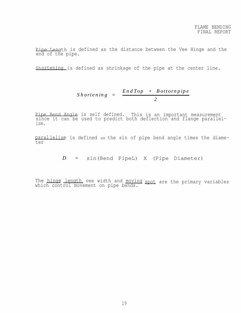
Pipe Length is defined as the distance between the Vee Hinge and theend of the pipe.
Shortening is defined as shrinkage of the pipe at the center line.
Shortening =EndTop + Bottornpipe
2
Pipe Bend Angle is self defined. This is an important measurementsince it can be used to predict both deflection and flange parallel-ism.
parallelism is defined as the sin of pipe bend angle times the diame-ter
D = sin(Bend PipeL) X (Pipe Diameter)
The hinge lengtha vee width and movingwhich control movement on pipe bends.
spot are the primary variables
19
FLAME BENDIFINAL REPO
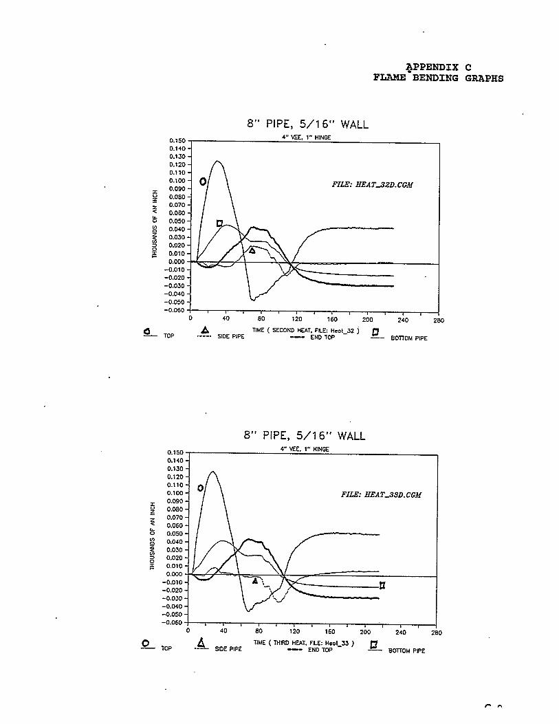
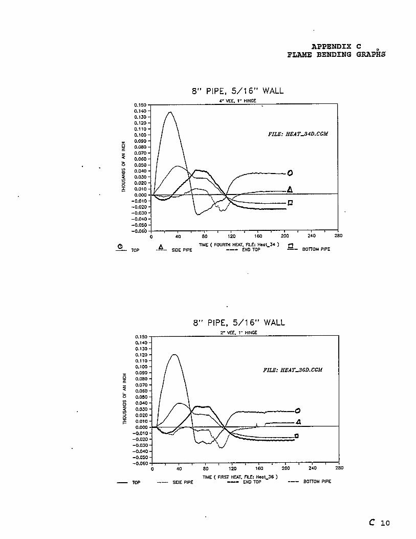
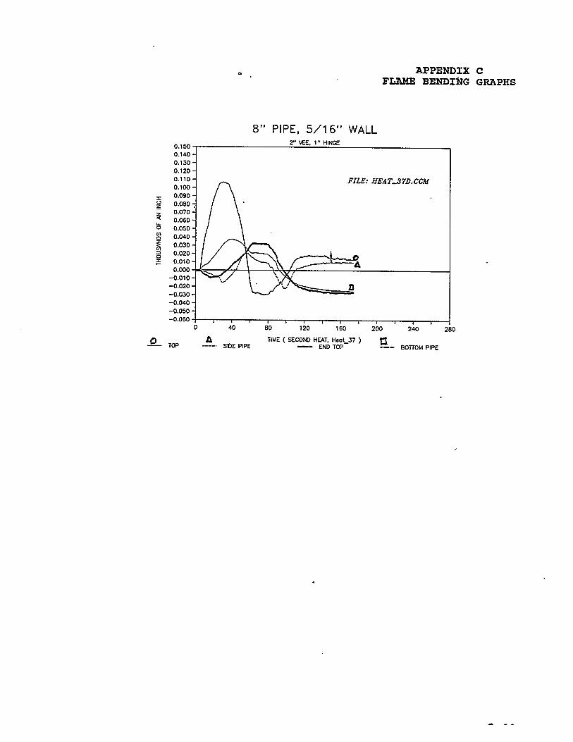
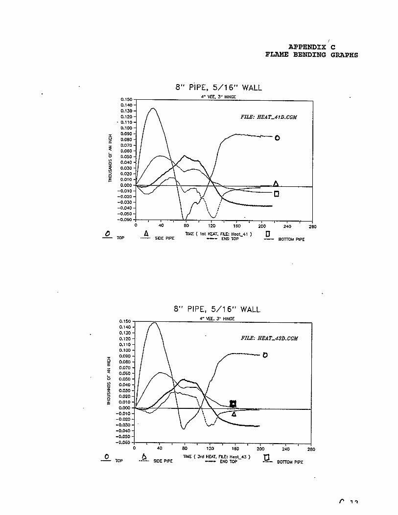
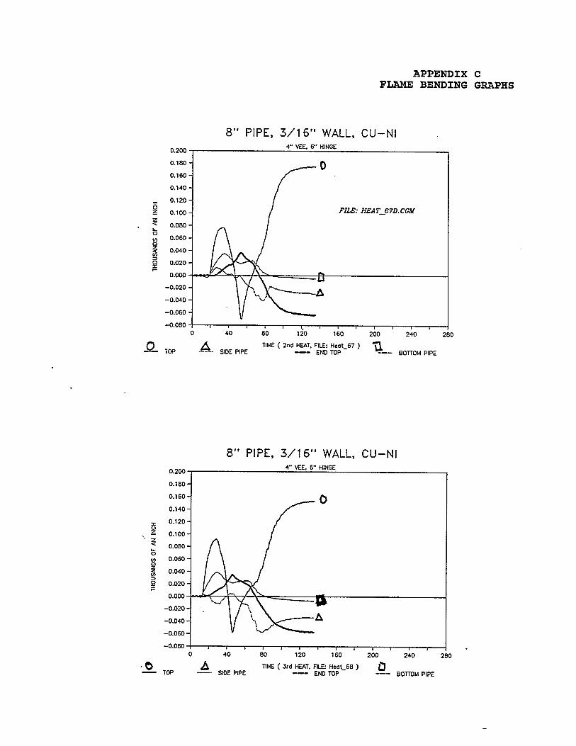
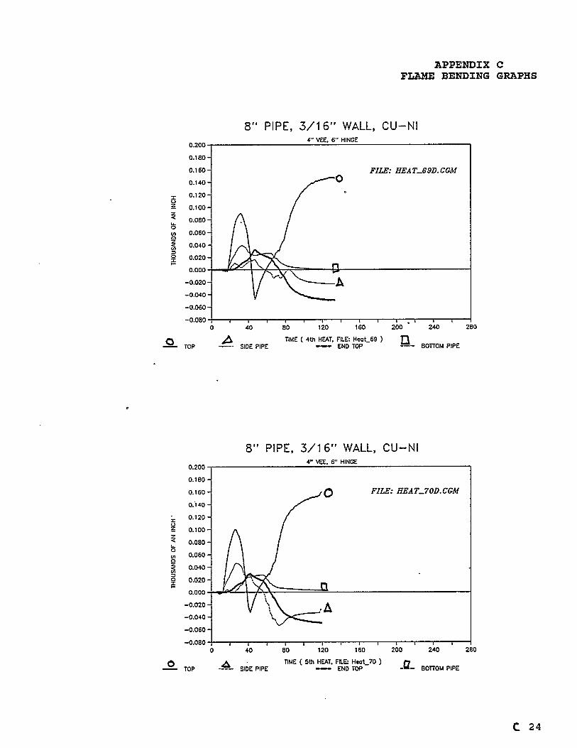
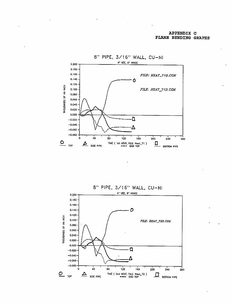
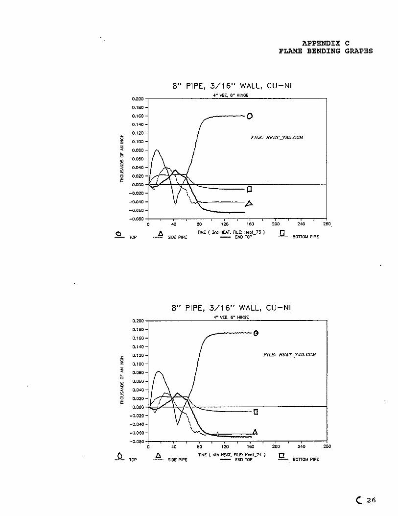
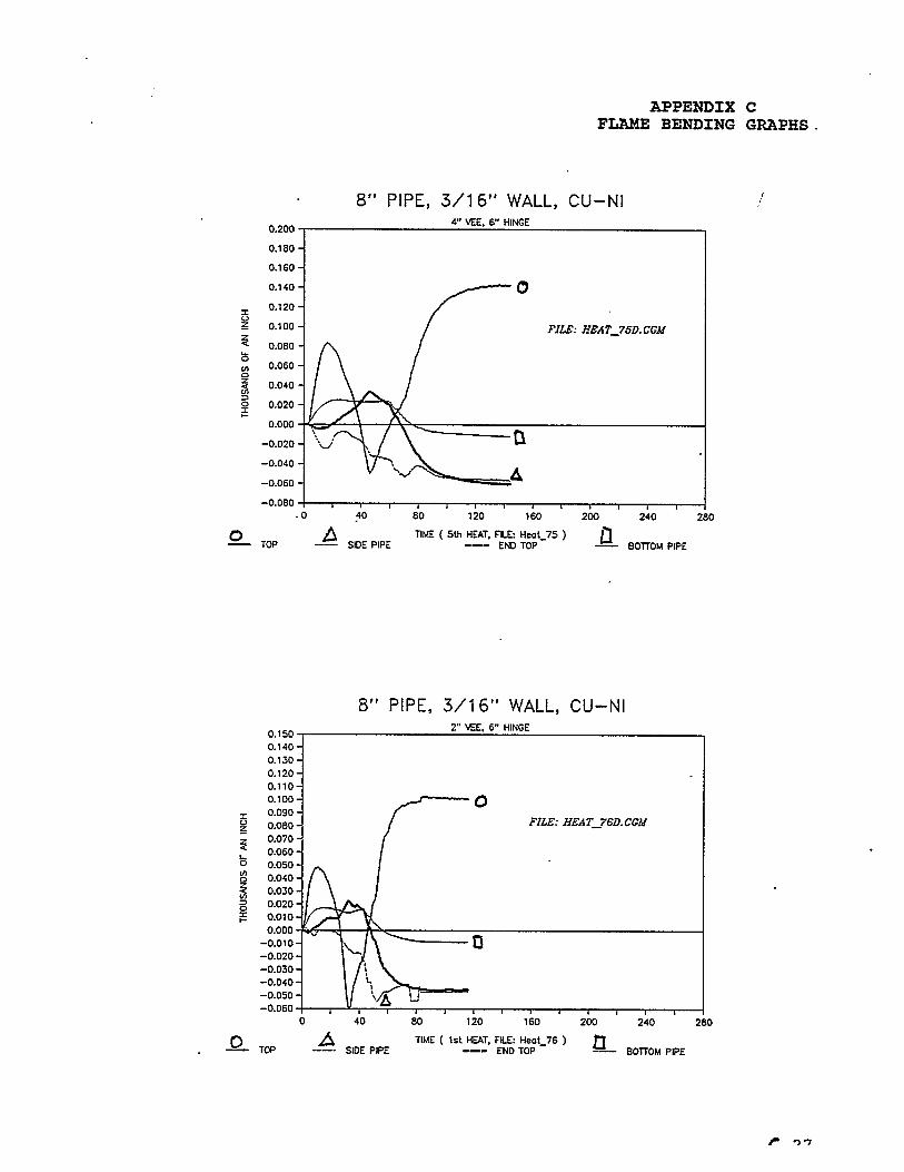
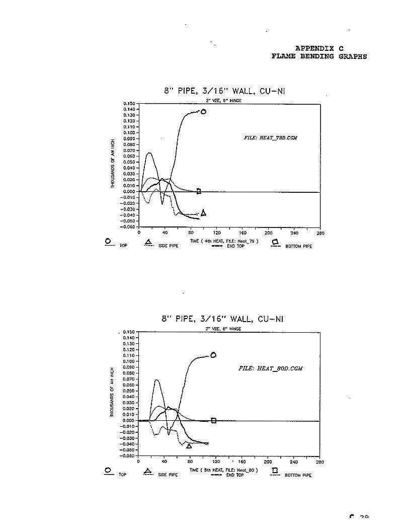
4.1.5 Typical Time / Motion PlotsThe Puget Sound Naval Shipyard is the only shipyard which currentlyflame bends pipe on a regular basis. Code 138 is present at eachflame bending production job to assist and monitor. Most facilitiesrely on a highly skilled small core group of mechanics to performthis work. This core group of skilled mechanics are very good atpredicting the amount of pipe movement. The emphasis in this studyon motion is an attempt to build a significant data base sufficientto predict many pipe deflection questions and provide direction forfuture work.
Pipe movement (deflection and shortening) is information which themechanic must have to predict what will happen when heat is appliedto the pipe. Other factors of the job which are of importance to thmechanic are accessibility, pipe restraint, and safety.
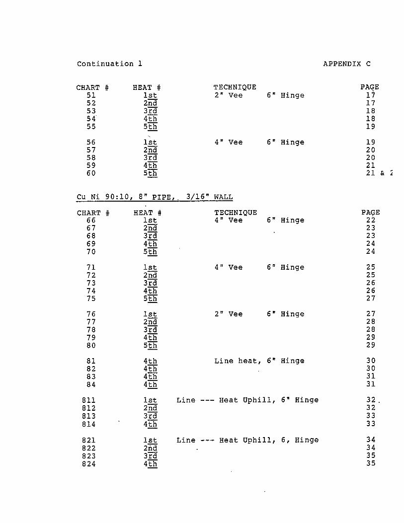
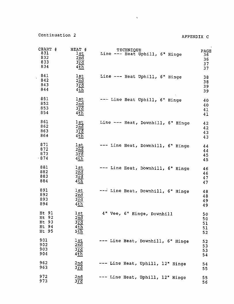
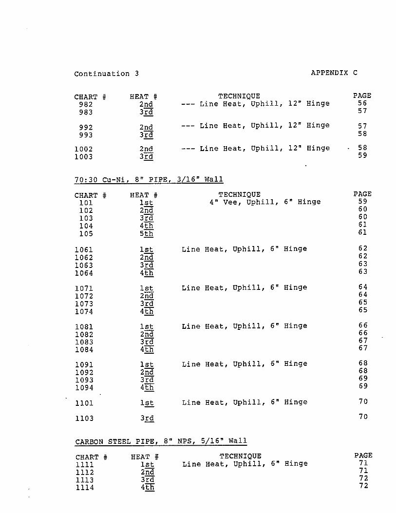
There are 225 individual plots of movement. This data are containedin APPENDIX A.
To assist the reader in understanding how a pipe moves as it is beinheated, a typical time versus movement (deflection) plot is explainein detail. The following figures are actual time - deflection curveobtained from a selected heat.
20
FLAME BENDINGFINAL REPORT
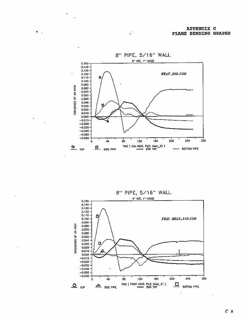
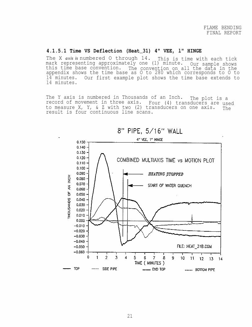
4.1.5.1 Time VS Deflection (Heat_31) 4" VEE, l" HINGEThe X axis is numbered O through 14. This is time with each tickmark representing approximately one (1) minute. Our sample showsthis time base convention. The convention on all the data in theappendix shows the time base as O to 280 which corresponds to O to14 minutes. Our first example plot shows the time base extends to14 minutes.
The Y axis is numbered in Thousands of an Inch. The plot is arecord of movement in three axis. Four (4) transducers areto measure X, Y, & Z with two (2) transducers on one axis.result is four continuous line scans.
usedThe
21
FLAME BENDINFINAL REPOR
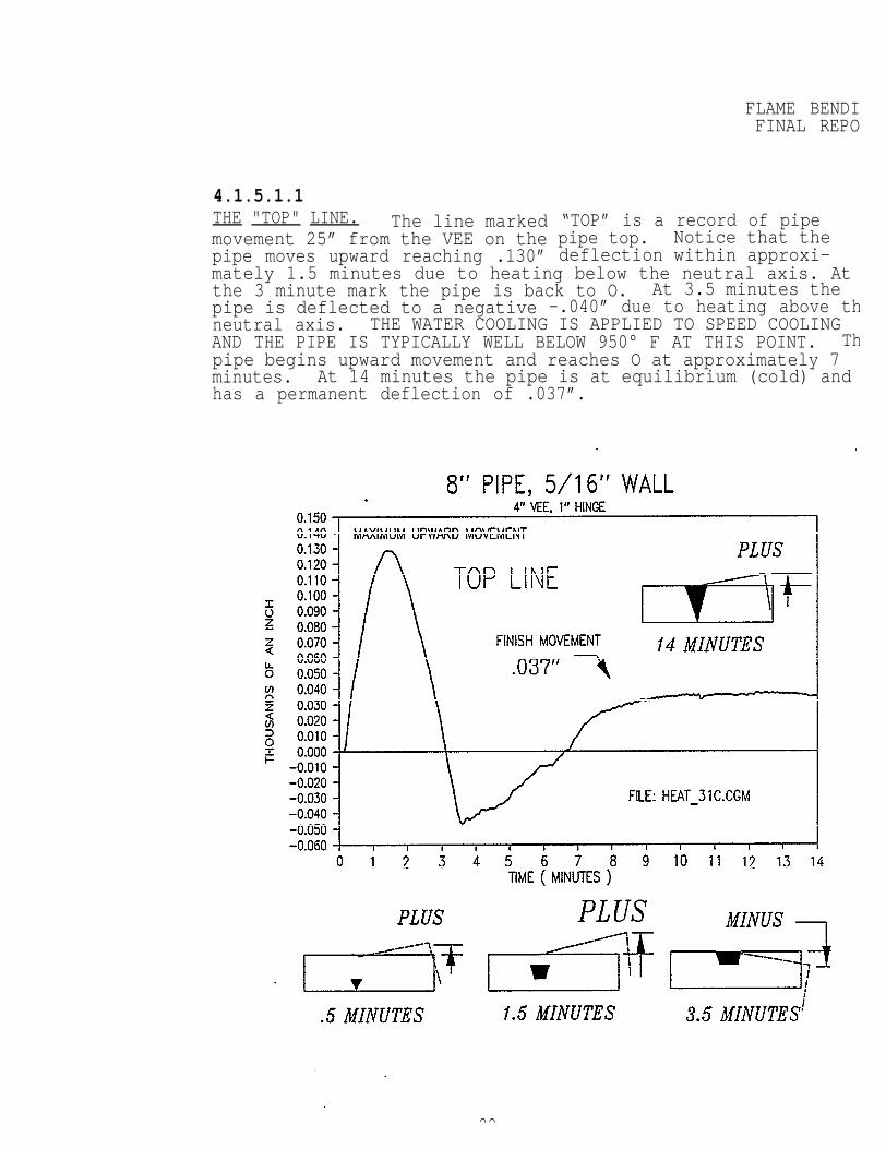
4.1.5.1.1THE "TOP" LINE. The line markedmovement 25” from the VEE on thepipe moves upward reaching .130”
“TOP” is a record of pipepipe top. Notice that thedeflection within approxi-
mately 1.5 minutes due to heating below the neutral axis. Atthe 3 minute mark the pipe is back to O. At 3.5 minutes thepipe is deflected to a negative -.040” due to heating above thneutral axis. THE WATER COOLING IS APPLIED TO SPEED COOLINGAND THE PIPE IS TYPICALLY WELL BELOW 950° F AT THIS POINT. Thpipe begins upward movement and reaches O at approximately 7minutes. At 14 minutes the pipe is at equilibrium (cold) andhas a permanent deflection of .037”.
22
23
FLAME BENDINFINAL REPOR
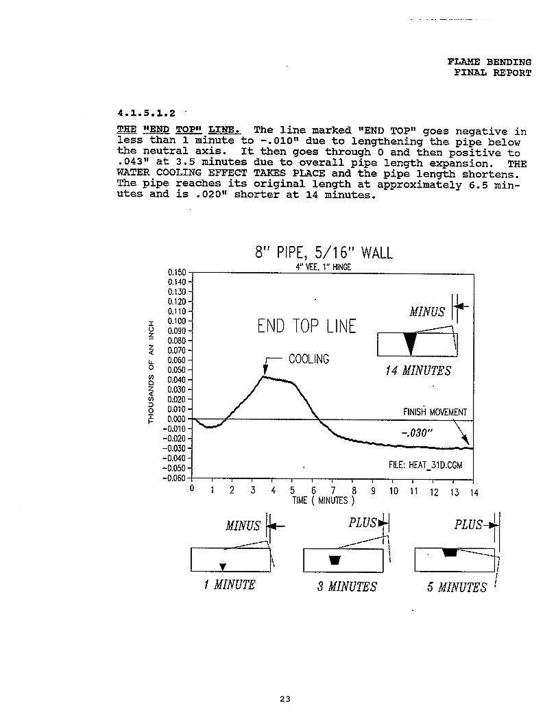
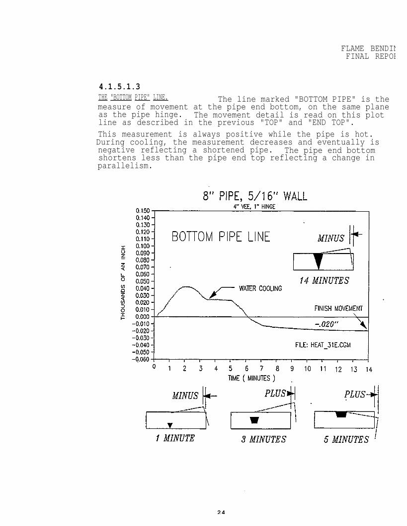
4.1.5.1.3THE "BOTTOM PIPE" LINE. The line marked "BOTTOM PIPE" is themeasure of movement at the pipe end bottom, on the same planeas the pipe hinge. The movement detail is read on this plotline as described in the previous "TOP" and "END TOP".This measurement is always positive while the pipe is hot.During cooling, the measurement decreases and eventually isnegative reflecting a shortened pipe. The pipe end bottomshortens less than the pipe end top reflecting a change inparallelism.
24
FLAME BENDINGFINAL REPORT
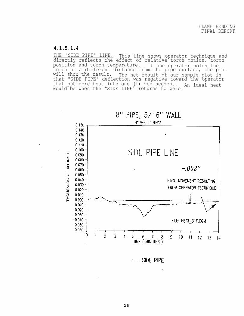
4.1.5.1.4THE "SIDE PIPE" LINE. This line shows operator technique anddirectly reflects the effect of relative torch motion, torchposition and torch temperature. If one operator holds thetorch at a different distance from the pipe surface, the plotwill show the result. The net result of our sample plot isthat "SIDE PIPE" deflection was negative toward the operatorthat put more heat into one (1) vee segment. An ideal heatwould be when the “SIDE LINE” returns to zero.
25
FLAME BENDINFINAL REPO
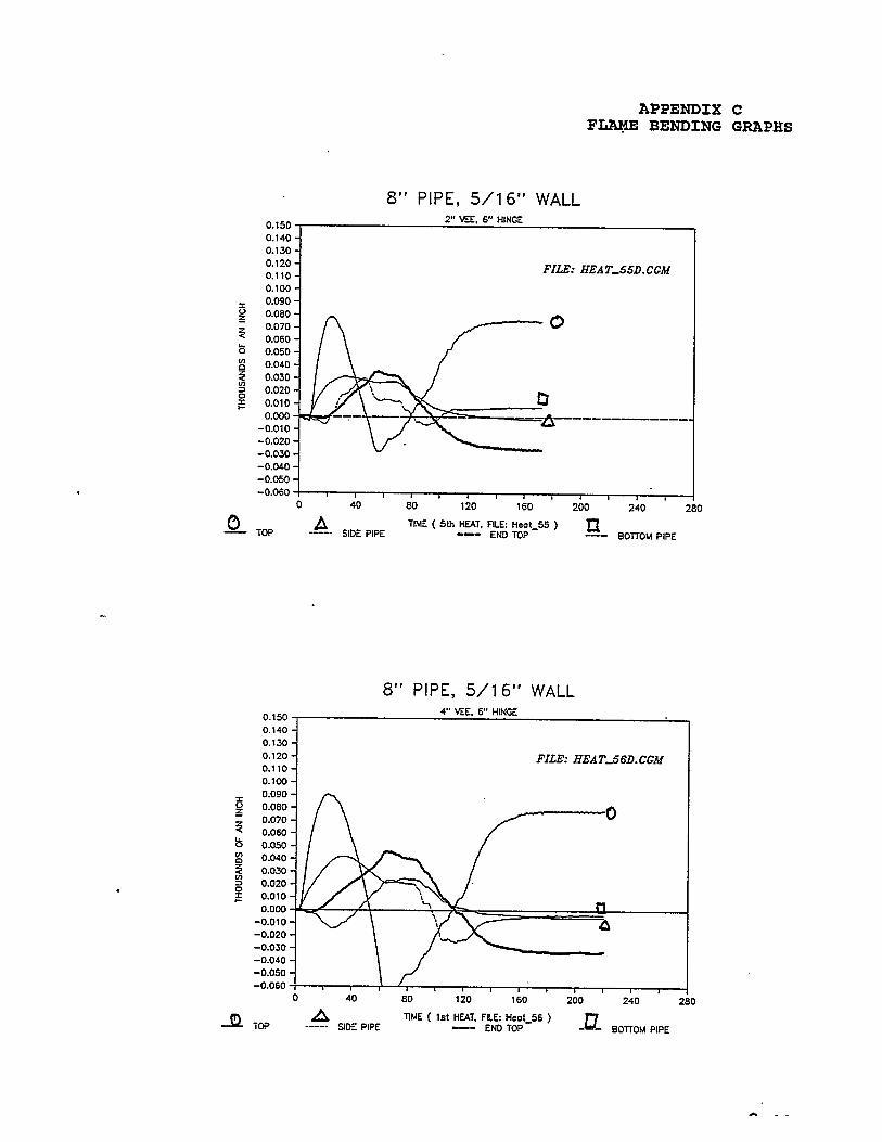
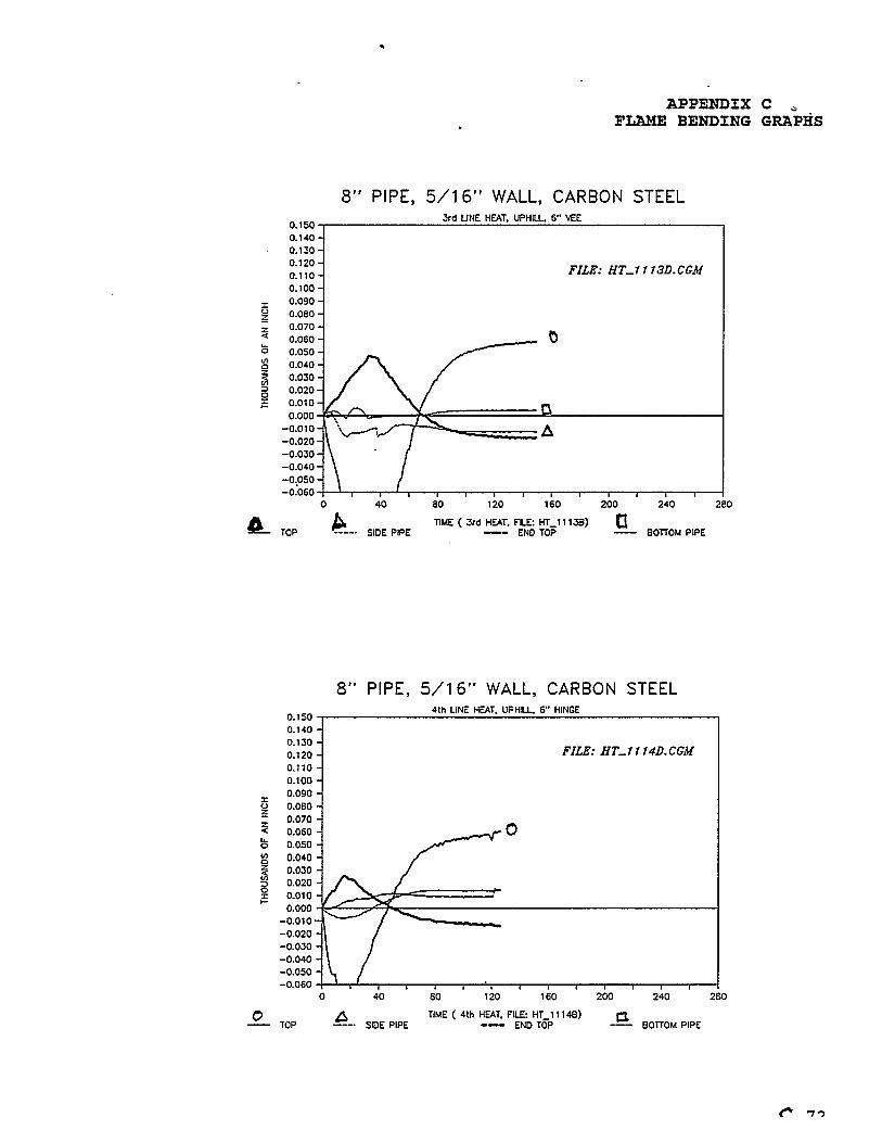
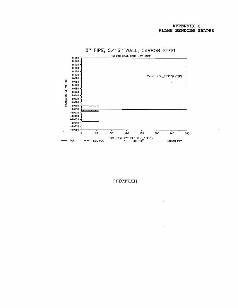
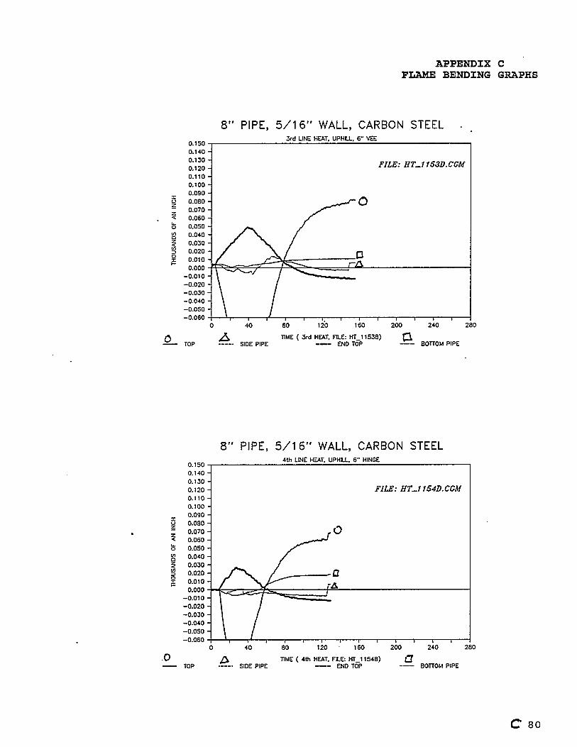
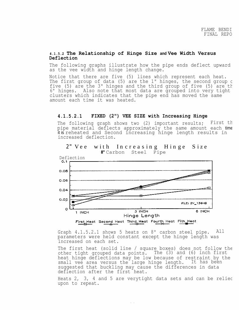
4.1.5.2 The Relationship of Hinge Size and Vee Width VersusDeflectionThe following graphs illustrate how the pipe ends deflect upwardas the vee width and hinge length change.Notice that there are five (5) lines which represent each heat.The first group of data (5) are the 1" hinges, the second group ofive (5) are the 3" hinges and the third group of five (5) are th6" hinges. Also note that most data are grouped into very tightclusters which indicates that the pipe end has moved the sameamount each time it was heated.
4.1.5.2.1 FIXED (2") VEE SIZE with Increasing Hinge
The following graph shows two (2) important results; First thpipe material deflects approximately the same amount each timeit is reheated and Second increasing hinge length results inincreased deflection.
2" V e e w i t h I n c r e a s i n g H i n g e S i z e 8" Carbon Steel Pipe
Deflection
1 I
Graph 4.1.5.2.1 shows 5 heats on 8" carbon steel pipe. Allparameters were held constant except the hinge length wasincreased on each set.The first heat (solid line / square boxes) does not follow theother tight grouped data points. The (3) and (6) inch firstheat hinge deflections may be low because of restraint by thesmall vee area versus the large hinge length. It has beensuggested that buckling may cause the differences in datadeflection after the first heat.Heats 2, 3, 4 and 5 are verytight data sets and can be reliedupon to repeat.
26
FLAME BENDINGFINAL REPORT”
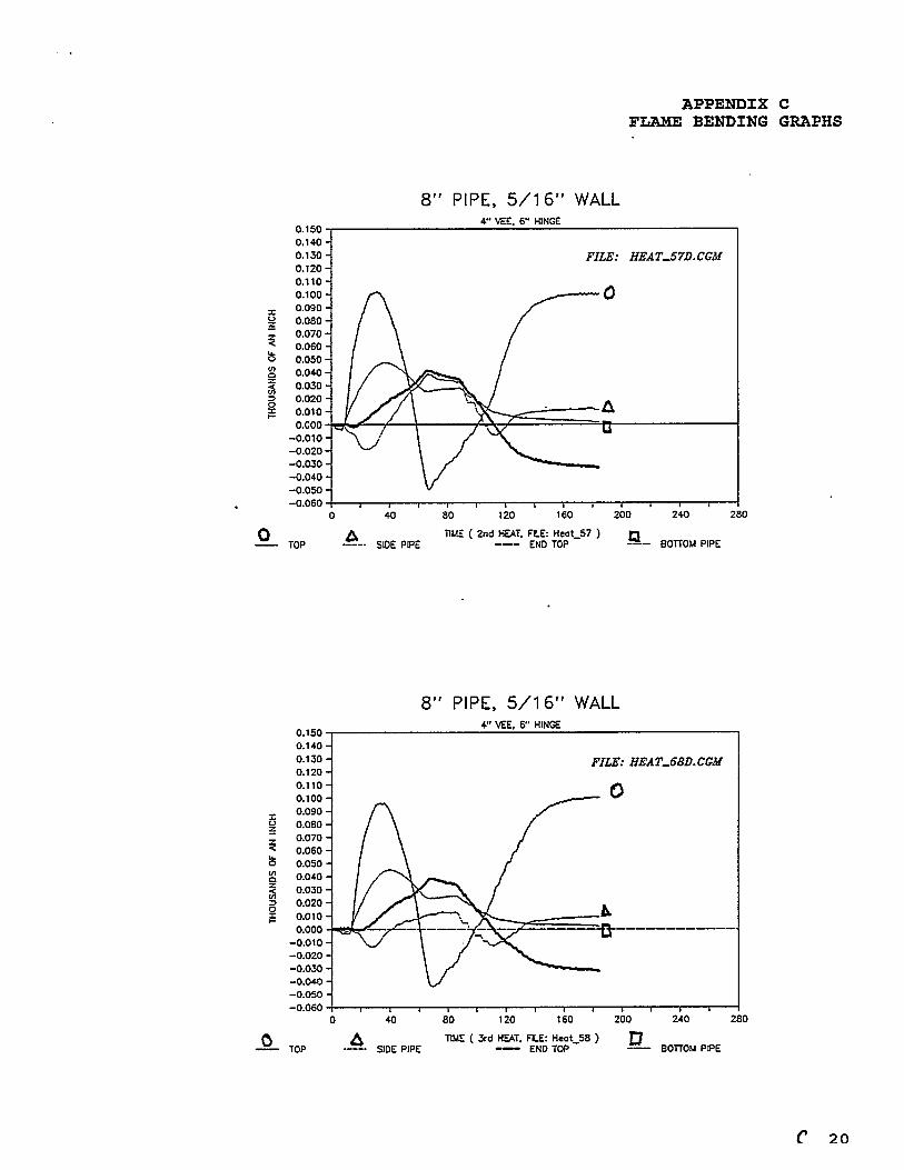
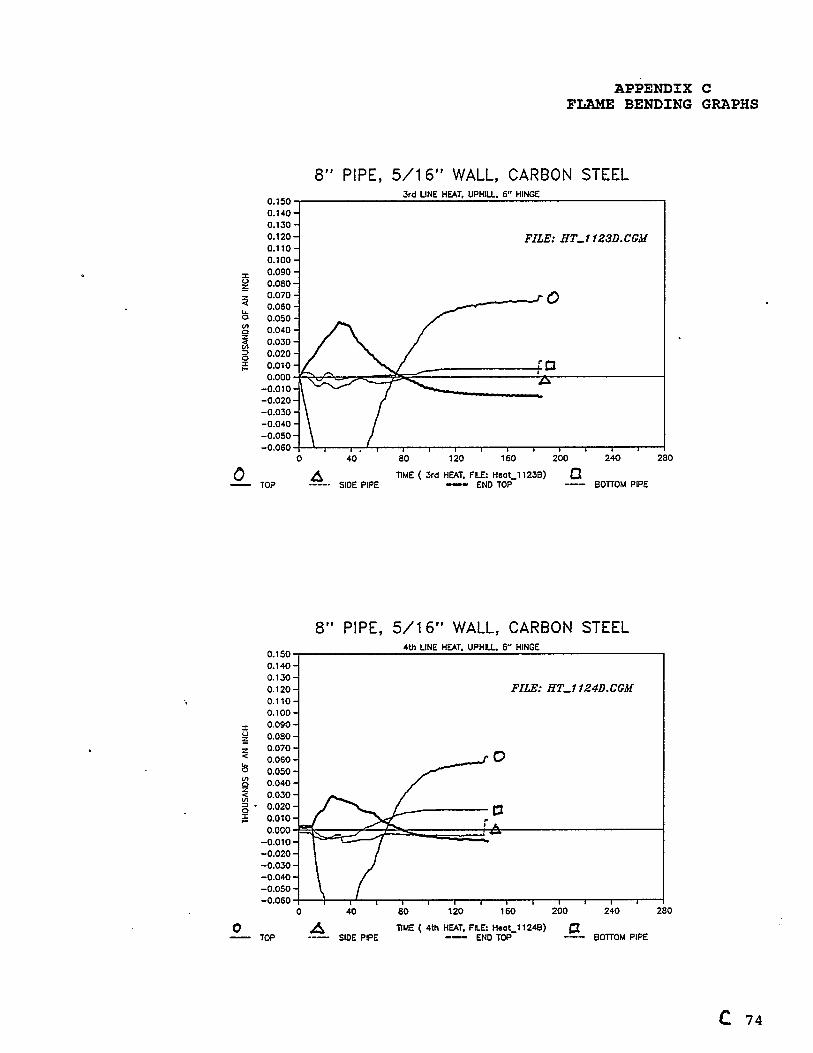
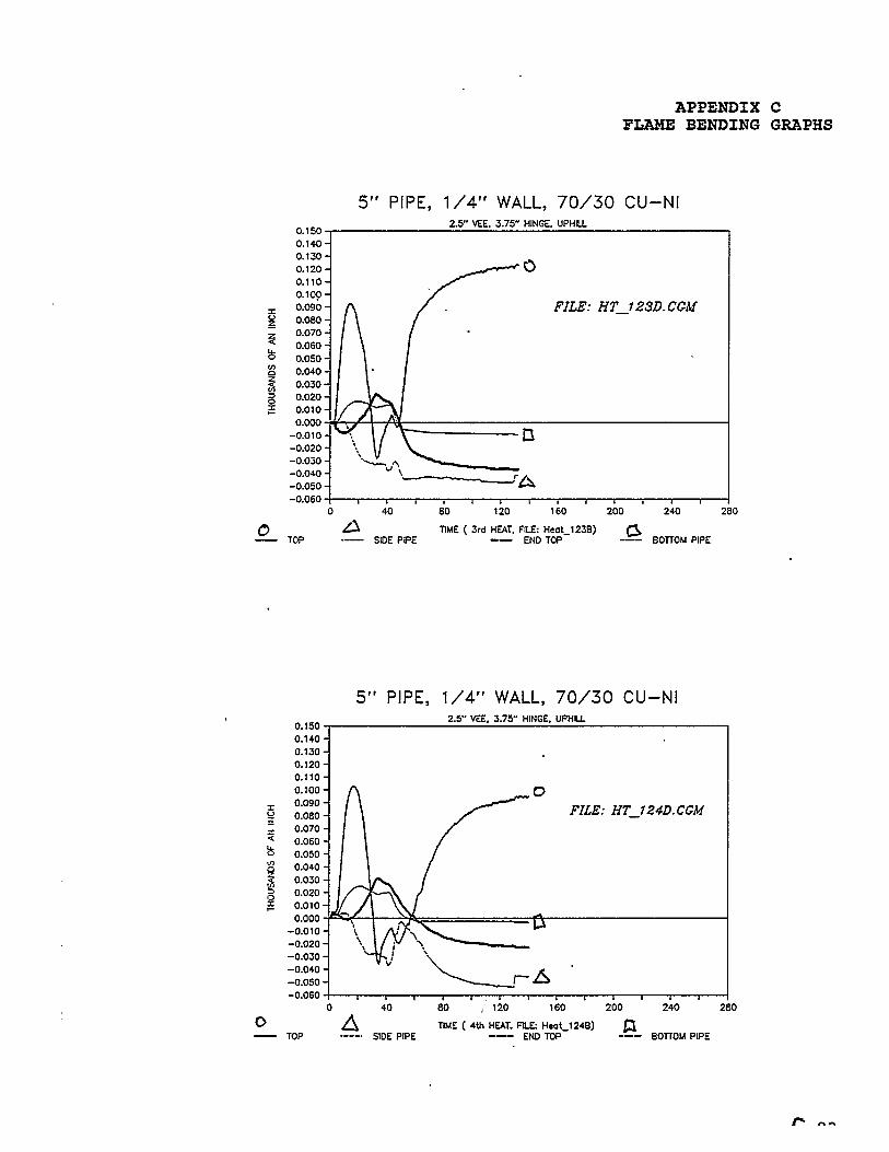
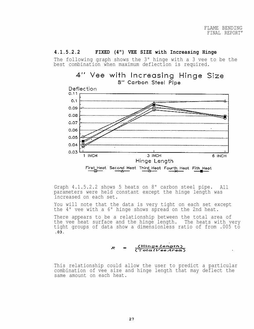
4.1.5.2.2 FIXED (4") VEE SIZE with Increasing HingeThe following graph shows the 3" hinge with a 3 vee to be thebest combination when maximum deflection is required.
Graph 4.1.5.2.2 shows 5 heats on 8" carbon steel pipe. Allparameters were held constant except the hinge length wasincreased on each set.You will note that the data is very tight on each set exceptthe 4" vee with a 6" hinge shows spread on the 2nd heat.There appears to be a relationship between the total area ofthe vee heat surface and the hinge length. The heats with verytight groups of data show a dimensionless ratio of from .005 to.03.
This relationship could allow the user to predict a particularcombinationsame amount
ofon
vee size and hinge length that may deflect theeach heat.
27
FLAME BENDIFINAL REPO
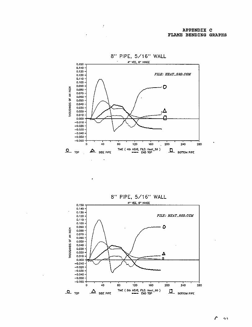
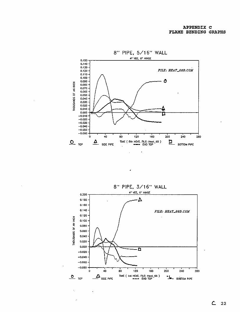
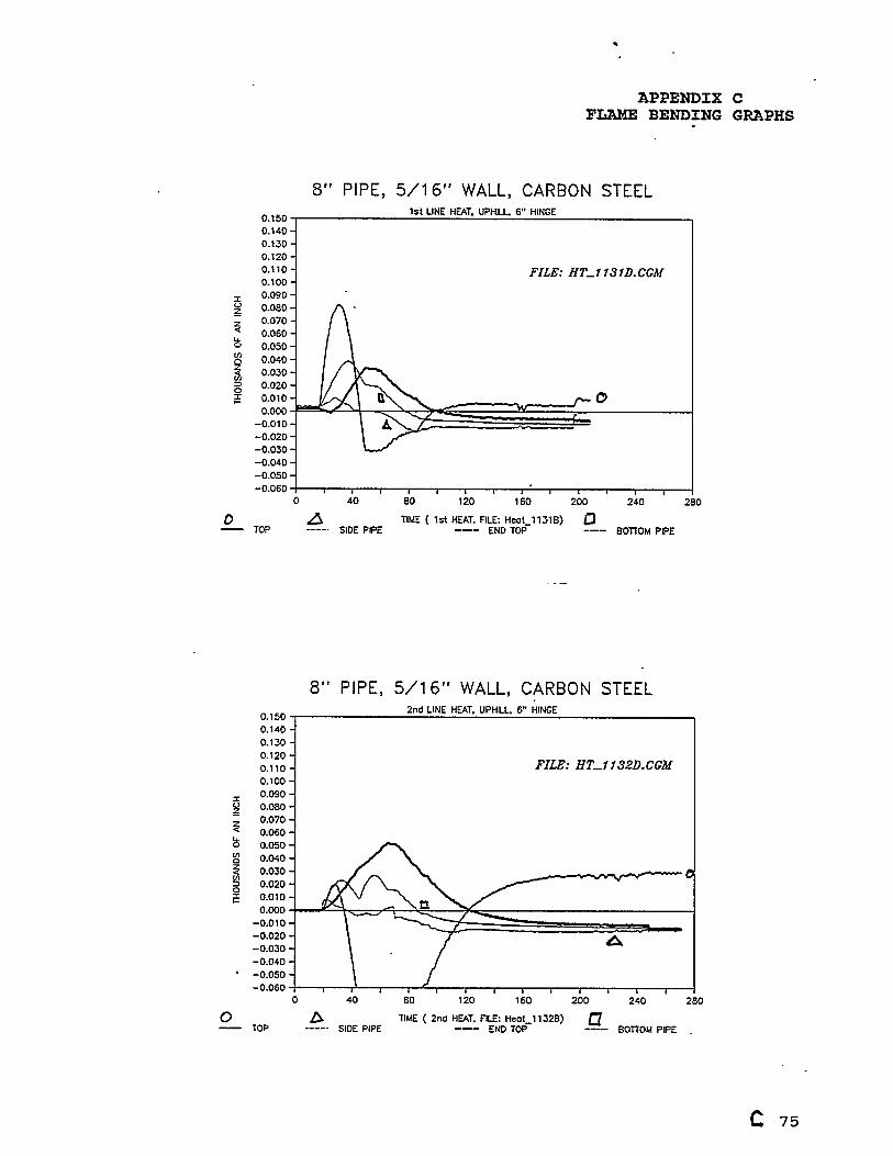
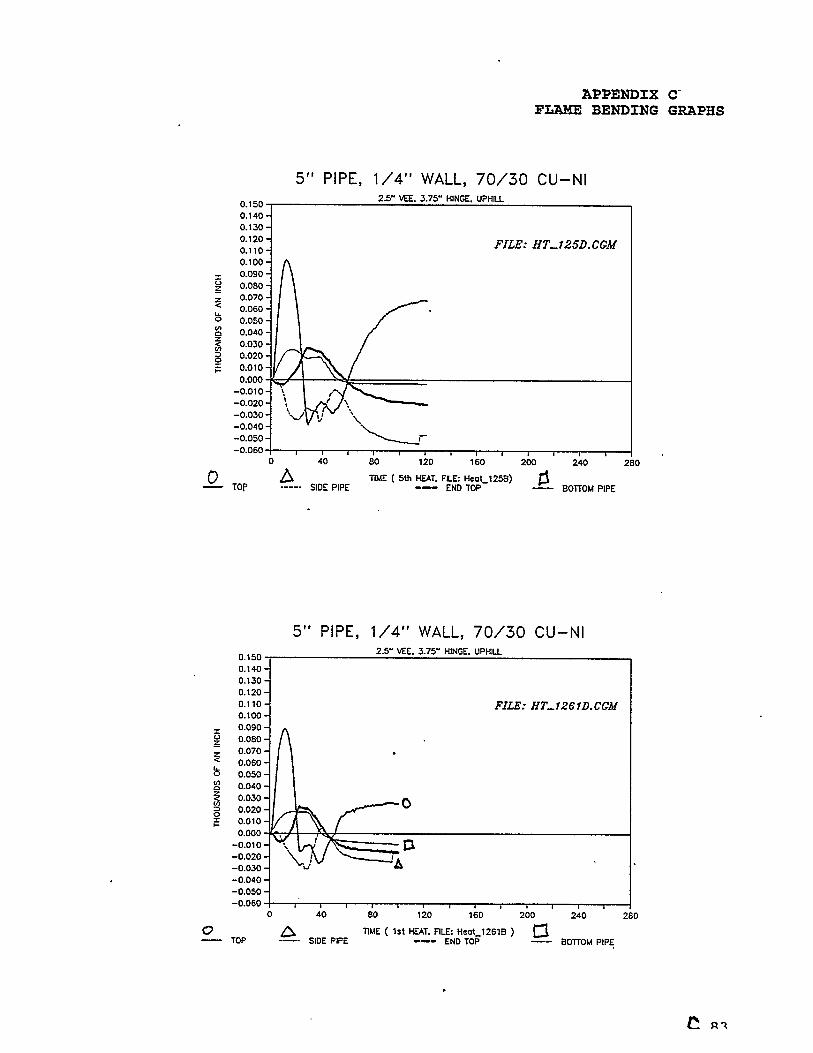
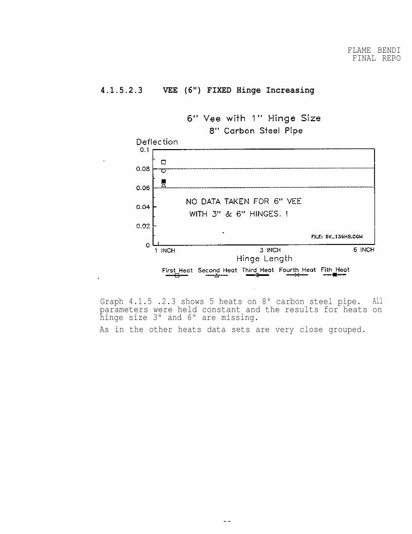
4.1.5.2.3 VEE (6") FIXED Hinge Increasing
Graph 4.1.5 .2.3 shows 5 heats on 8" carbon steel pipe. All parameters were held constant and the results for heats onhinge size 3" and 6" are missing.As in the other heats data sets are very close grouped.
28
FLAME BENDFINAL REPORT
4.1.6 Discussion of Results on Vee Hinges
It has been shown that vee heatsgeneral relationships that applyprimary parameters which control
Hinge lengthVee widthSpot temperature
are predictable. There are someto all vee heats on pipe. Thethese relationships are:
Regardless of how these parameters are adjusted, the finish pipe ALWAYS SHORTER AFTER HEATING.
4.2.6.1 Relationship of Hinge, Vee & Shortening
Short hinges + narrow vees = maximum shortening and minimumdeflection.
Short hinges + wide vees = maximum shortening at the End Bottomand maximum shortening and maximum deflection.
Long hingestions.
+
+
narrow vees
wide vees =
= minimum shortening and minimum deflec-
Long hingesEnd Bottom and medium deflections.
zero.(0) to minimum shortening at the
Long hinges = higher residual stress,greater instability.
Wide vees = chance for increased buckling.
increased pipe movement and
29
FLAME BENDINFINAL REPOR
4.1.7 Torch Travel Speed and Temperature GradientThe average travel speed of the moving spot was in the range of 1.5inches/minute to 3.5 inches/minute.
The overall average was 2.5 ipm. The amount of upset (movement ordeflection) did not move significantly outside of a group of datapoints when the slower travel speed was compared to the higher travespeed.
The essential variable was spot size control and surrounding temperature of the support base metal of the pipe. The operators adjustedthe torch standoff distance to control spot size and color. TO dothis they adjusted the travel speed in the range of 1.5 to 3.5 ipm.
These values were calculated from the time base on selected dataplots for 8" diameter pipe.
4.1.8 Determination of Residual StressNo experiments were conducted for measurement of residual stress.
FLAME BENDINGFINAL REPORT
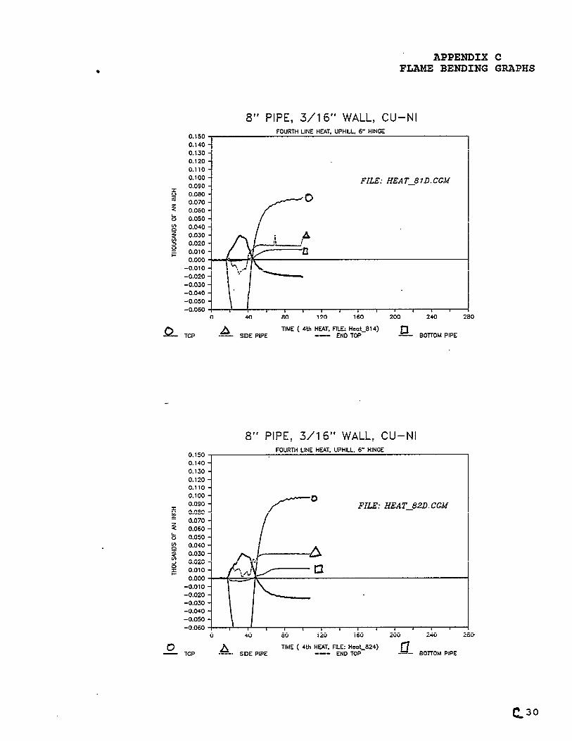
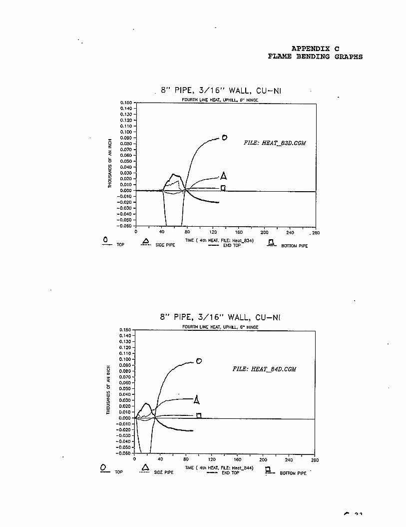
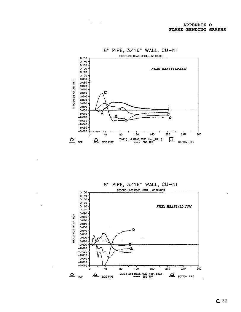
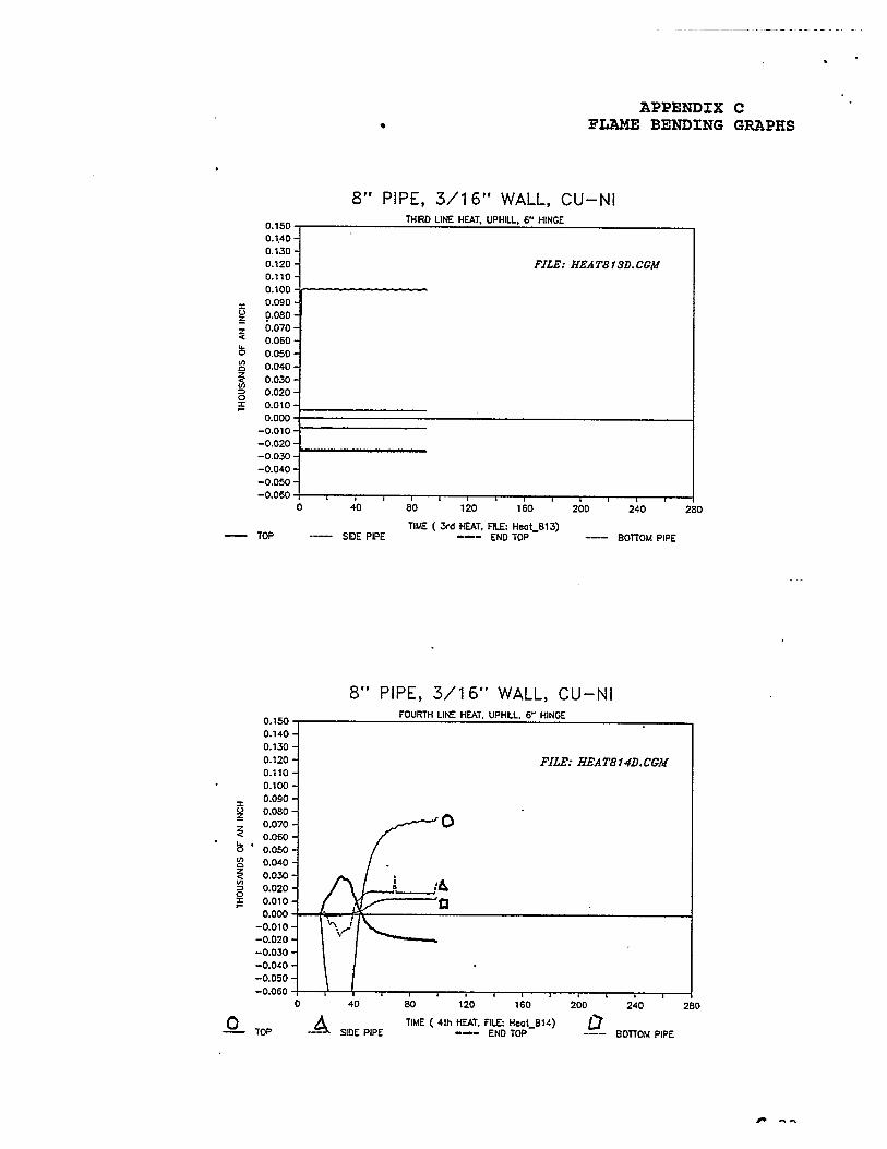
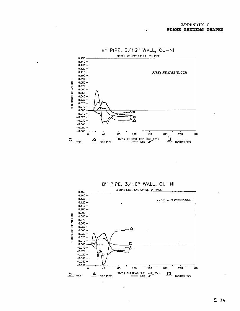
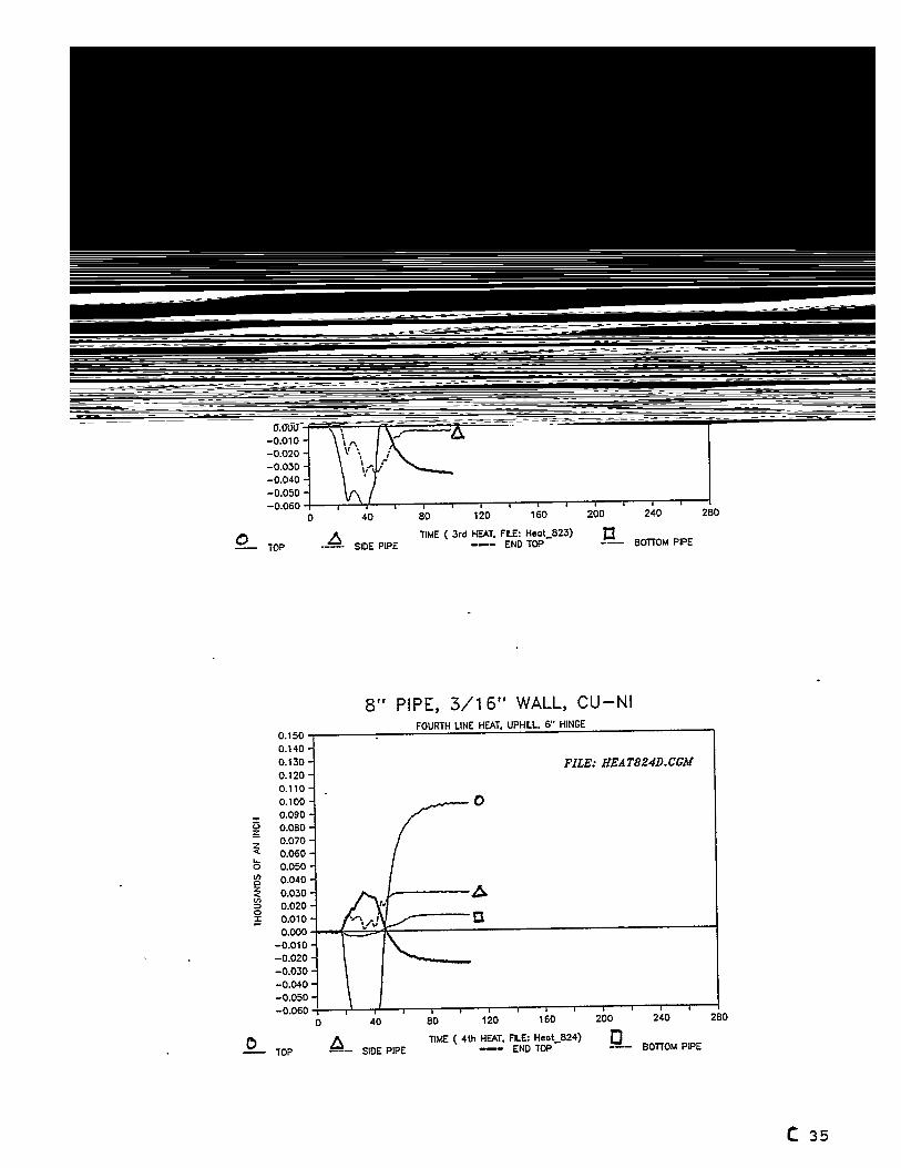
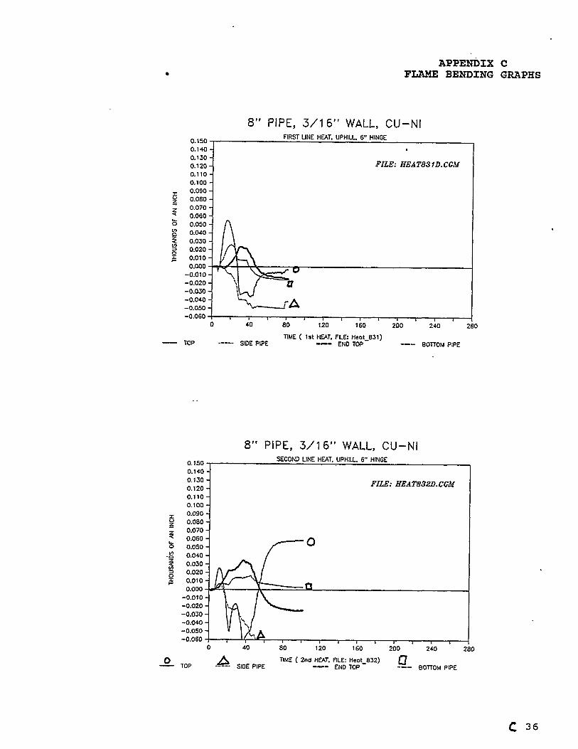
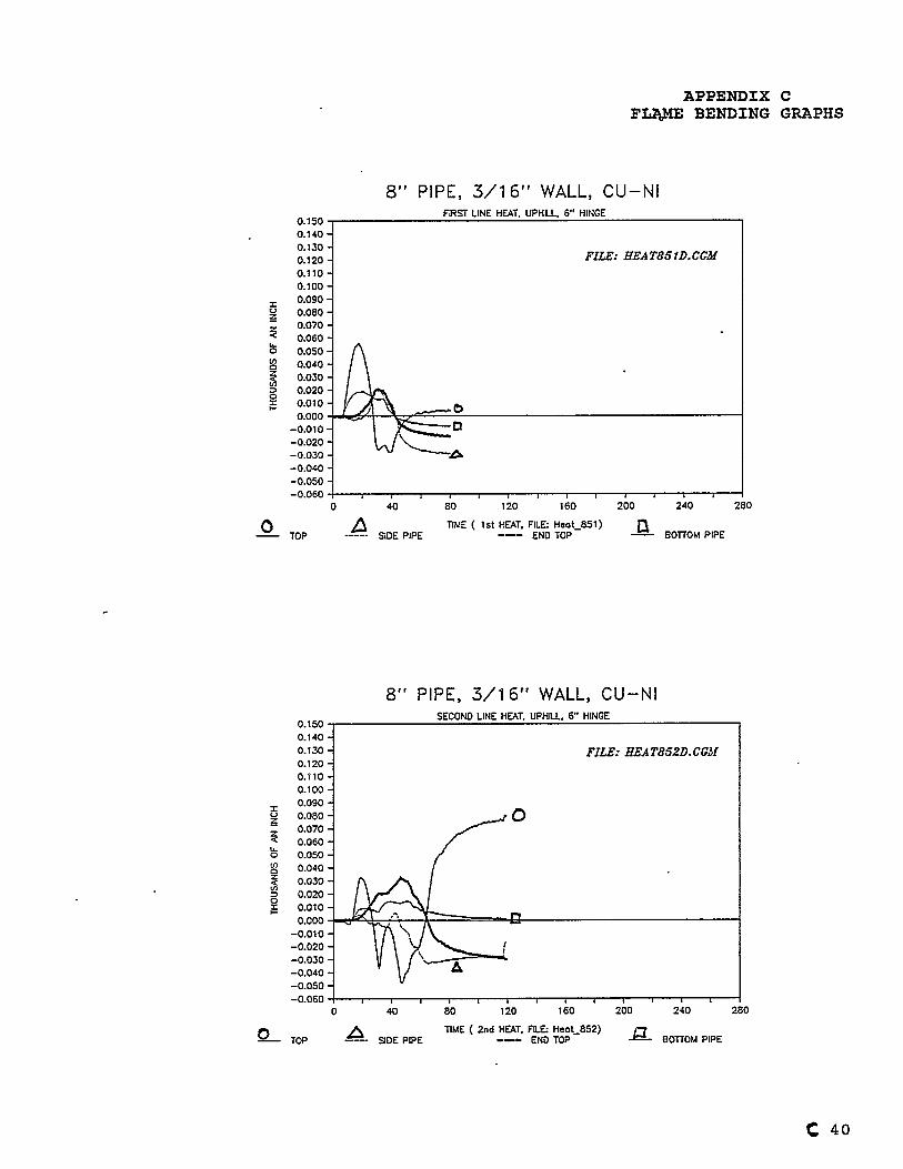
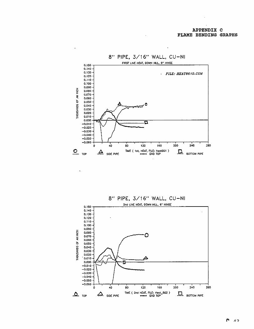
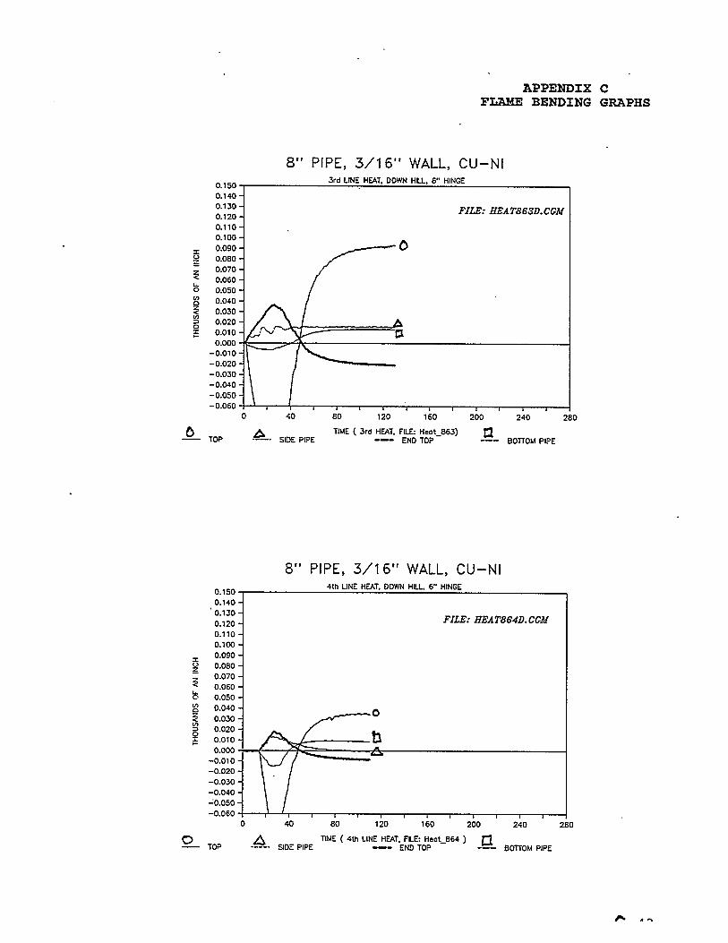
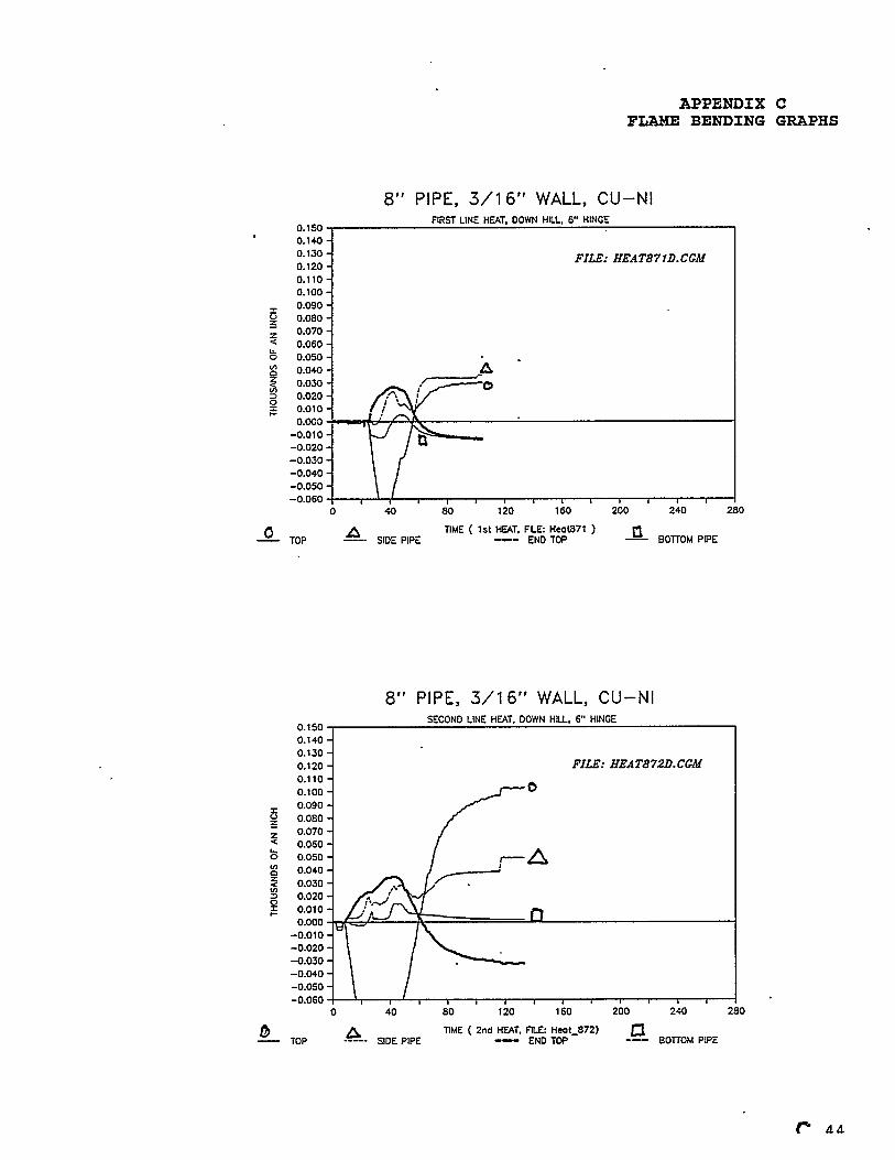
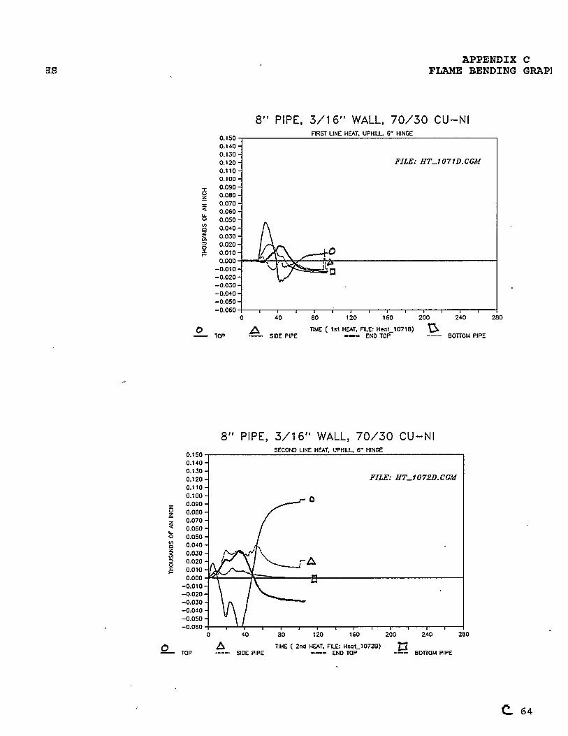
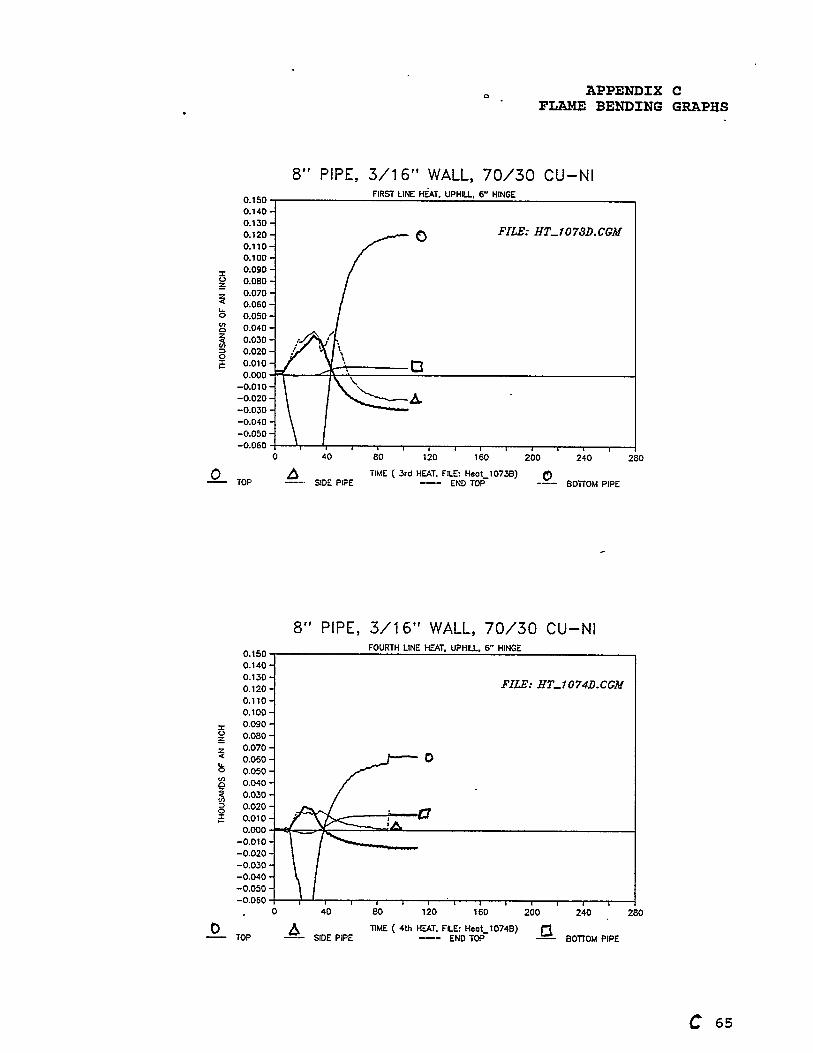
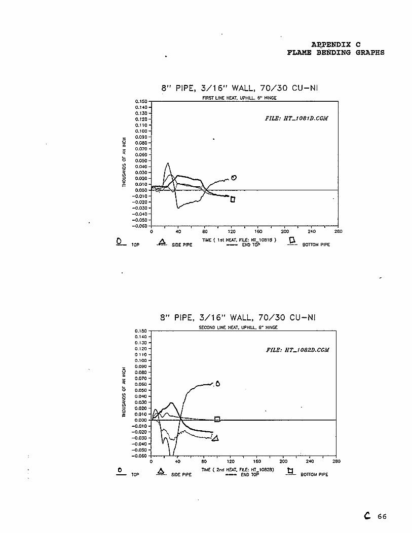
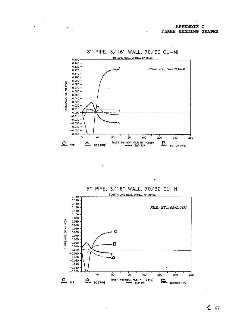
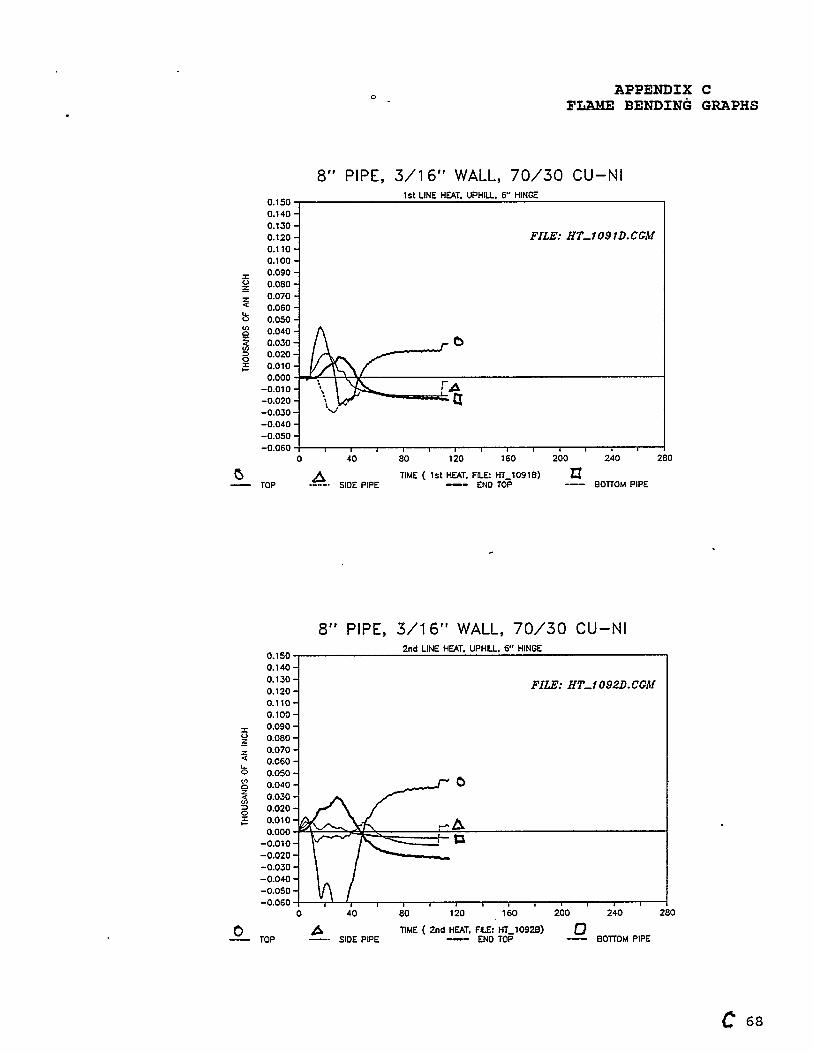
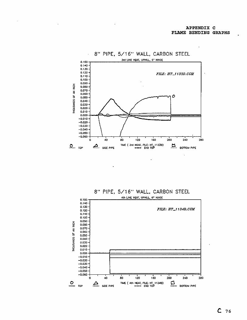
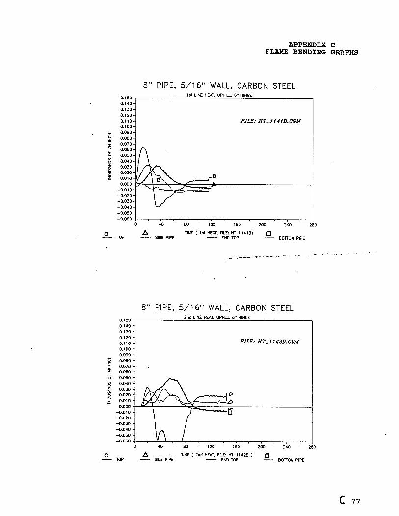
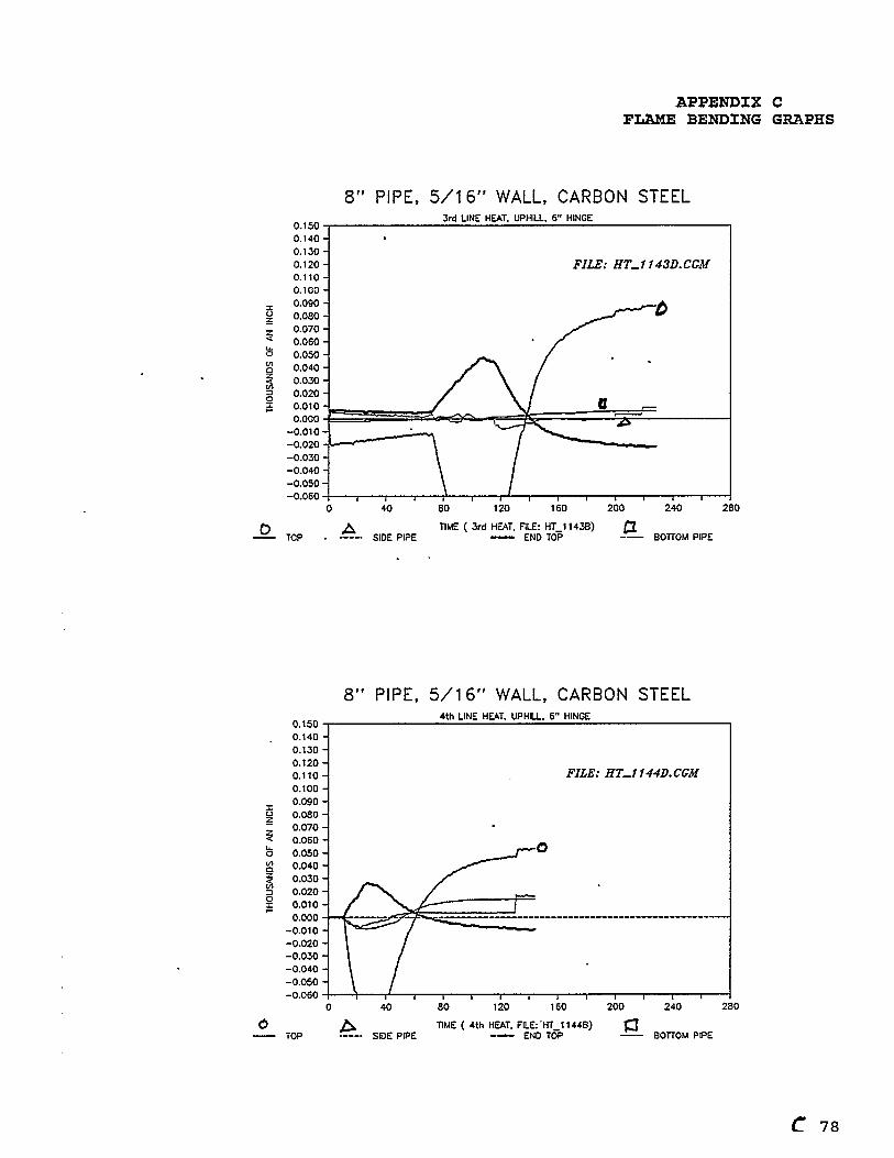
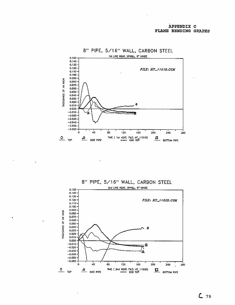
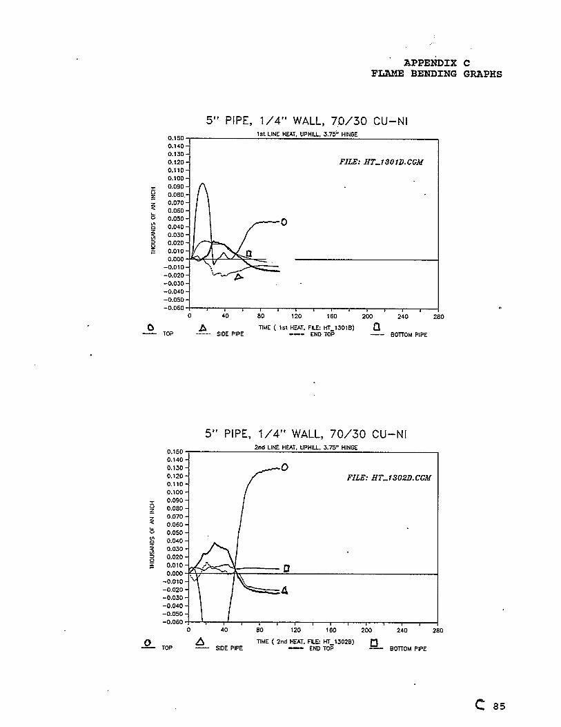
4.2 Line Heat Testing
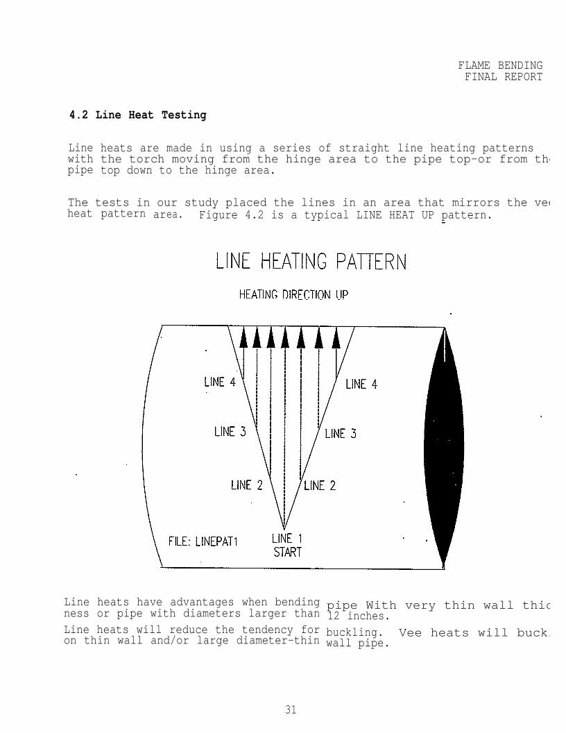
Linewithpipe
heats are made in using a series of straight line heating patternsthe torch moving from the hinge area to the pipe top-or from thetop down to the hinge area.
The tests in our study placed the lines in an area that mirrors the veeheat pattern area. Figure 4.2 is a typical LINE HEAT UP pattern.
Line heats have advantages when bendingness or pipe with diameters larger thanLine heats will reduce the tendency foron thin wall and/or large diameter-thin
pipe With very thin wall thic12 inches.buckling. Vee heats will bucklwall pipe.
31
FLAME BENDINFINAL REPOR
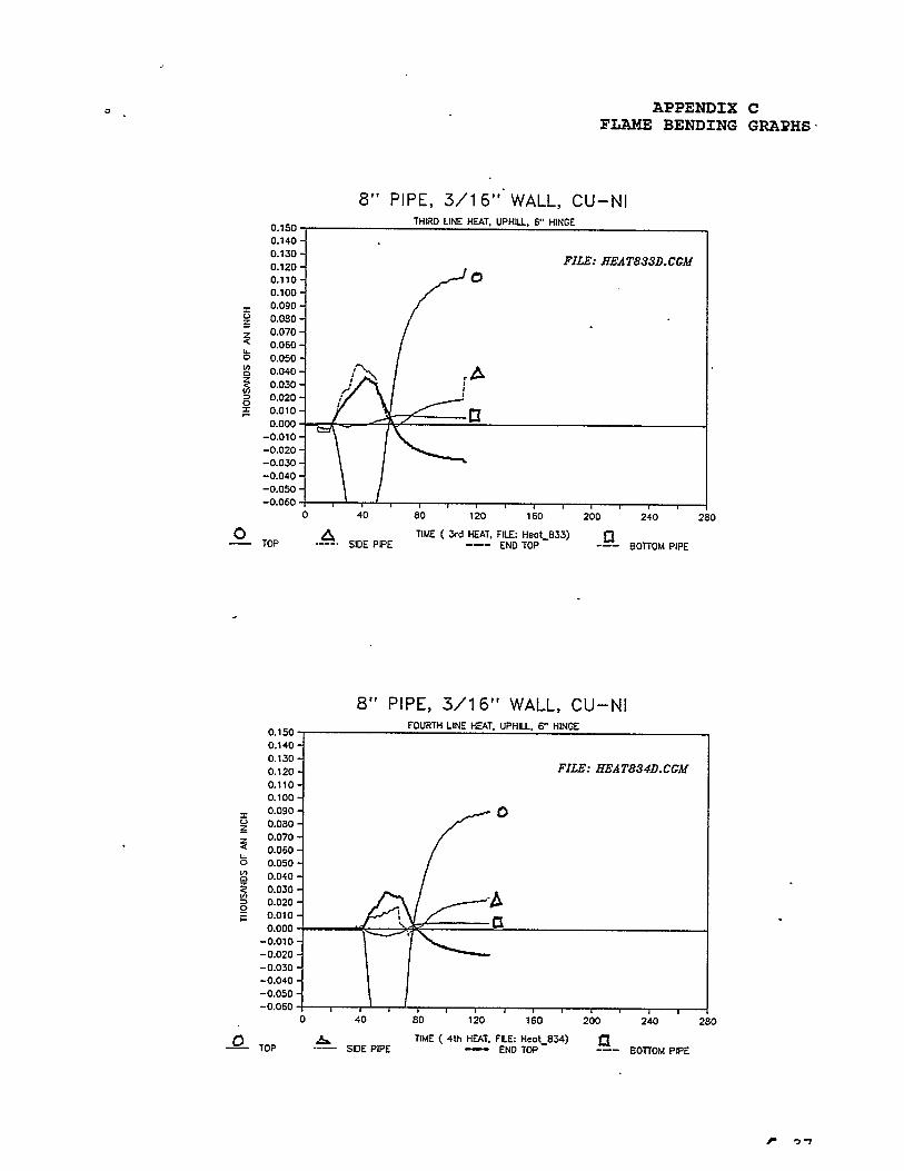
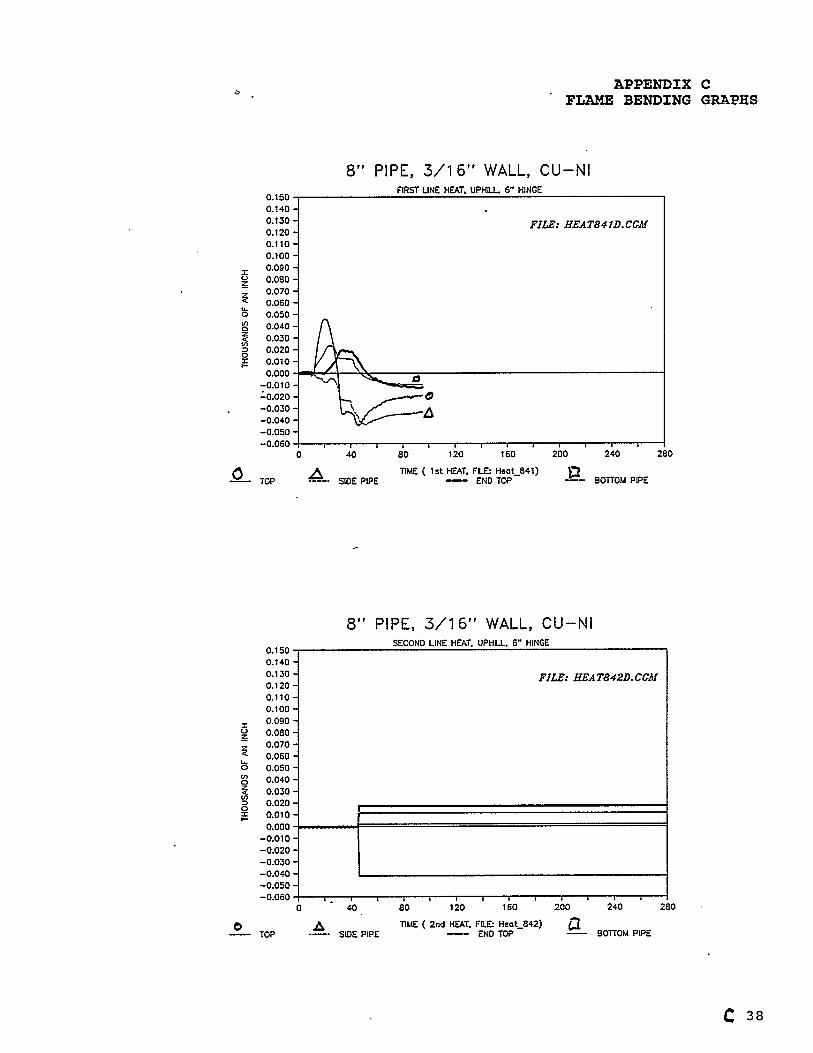
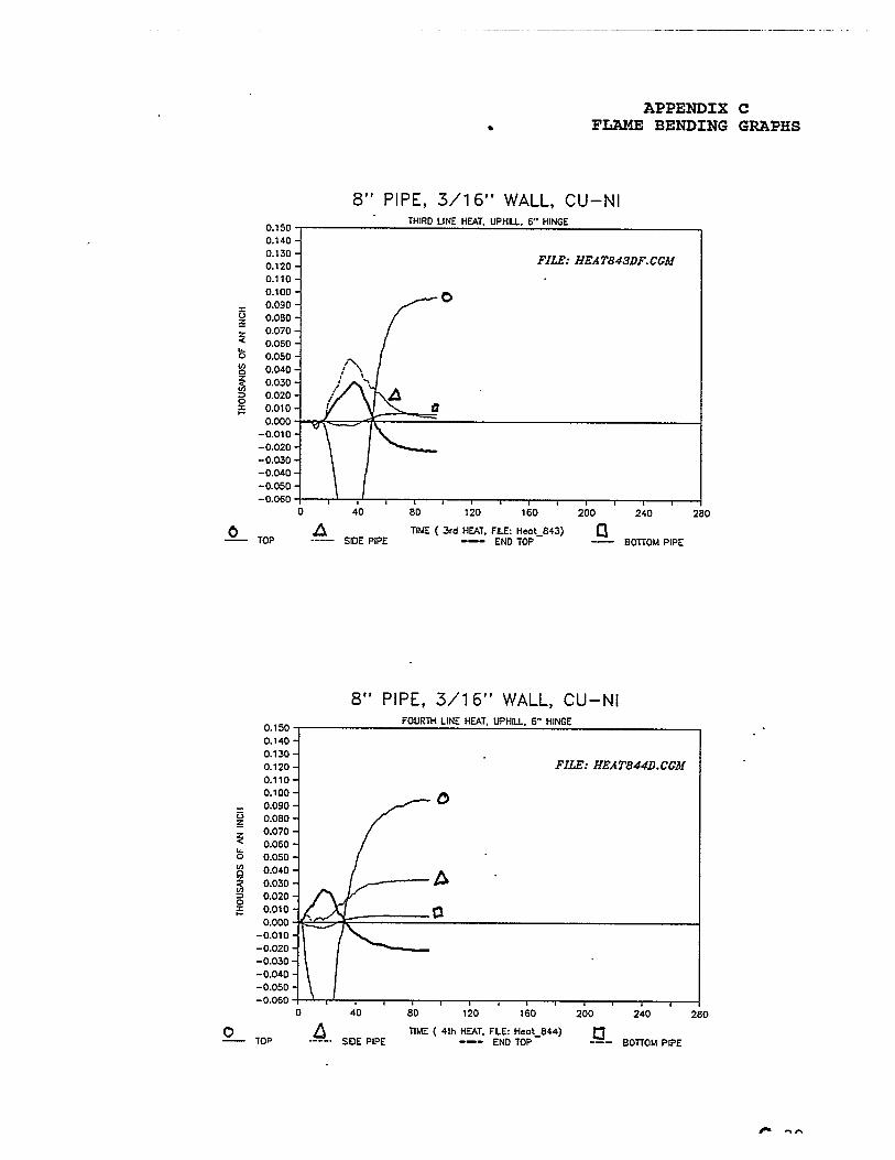
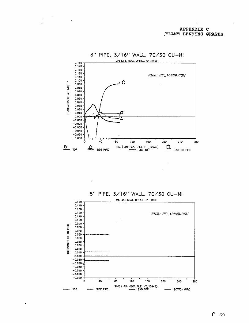
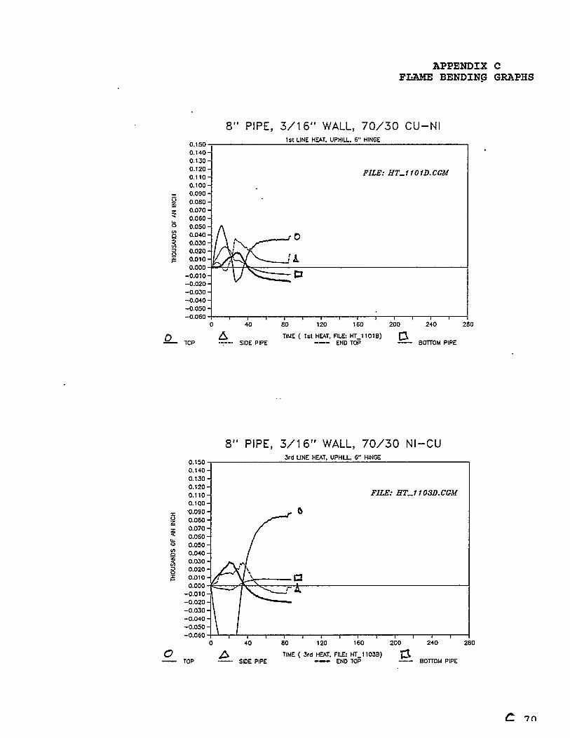
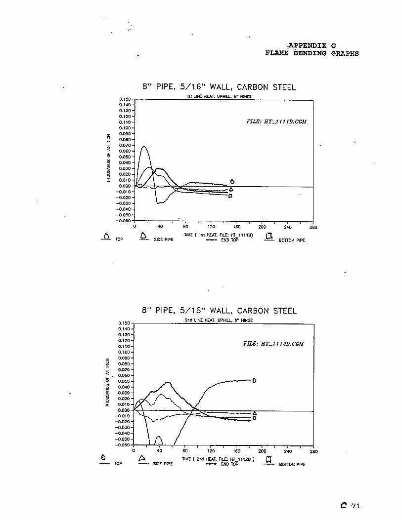
4.2.1 Relationship Between Line/Vee Heat Pattern and Deflection
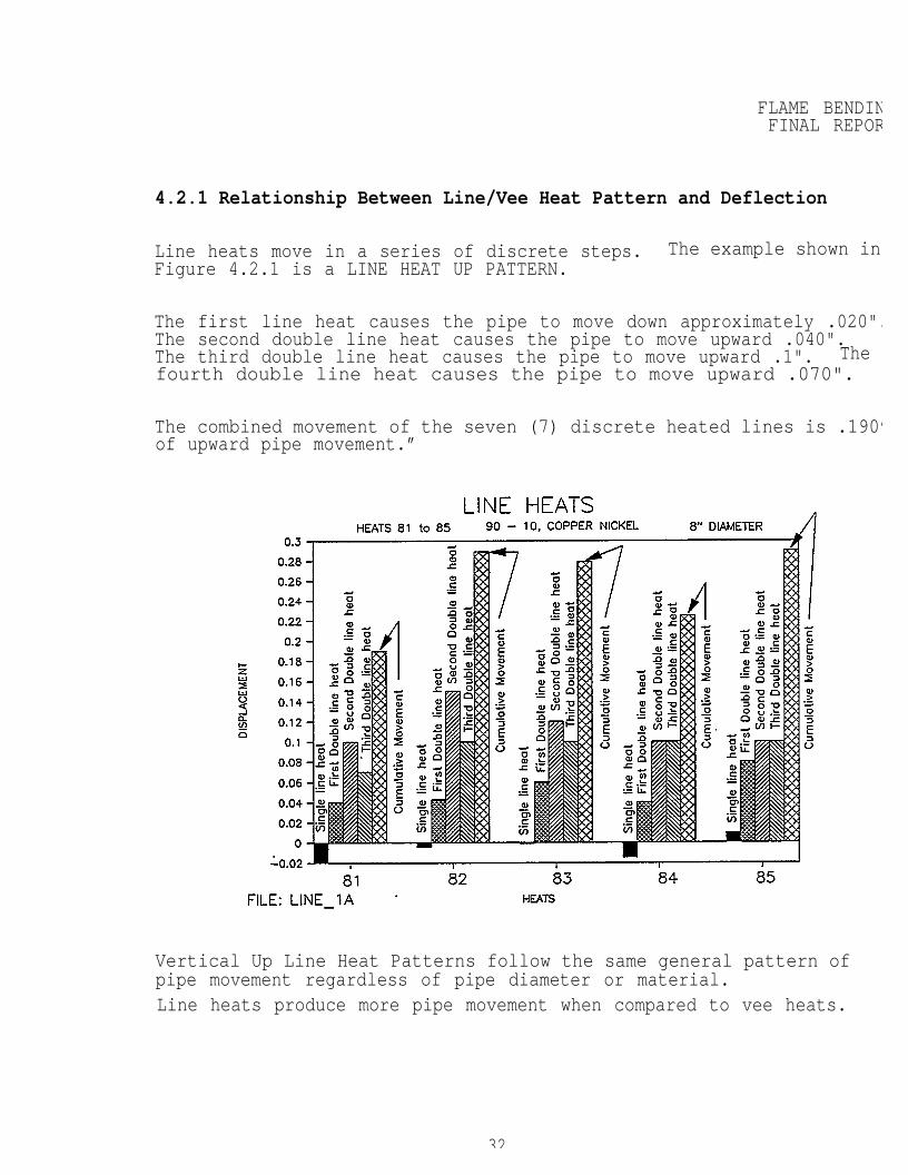
Line heats move in a series of discrete steps. The example shown inFigure 4.2.1 is a LINE HEAT UP PATTERN.
The first line heat causes the pipe to move down approximately .020".The second double line heat causes the pipe to move upward .040".The third double line heat causes the pipe to move upward .1". Thefourth double line heat causes the pipe to move upward .070".
The combined movement of the seven (7) discrete heated lines is .190”of upward pipe movement.”
Vertical Up Line Heat Patterns follow the same general pattern ofpipe movement regardless of pipe diameter or material.Line heats produce more pipe movement when compared to vee heats.
32
FLAME BENDINGFINAL REPORT
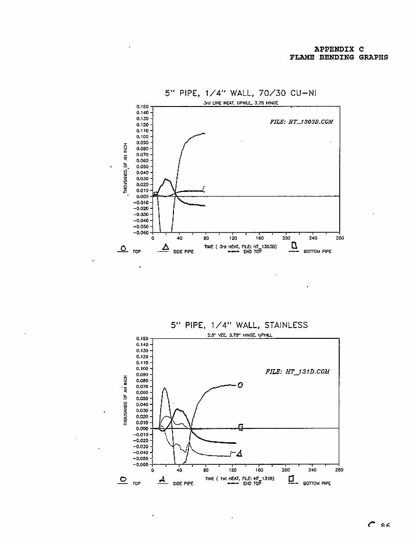
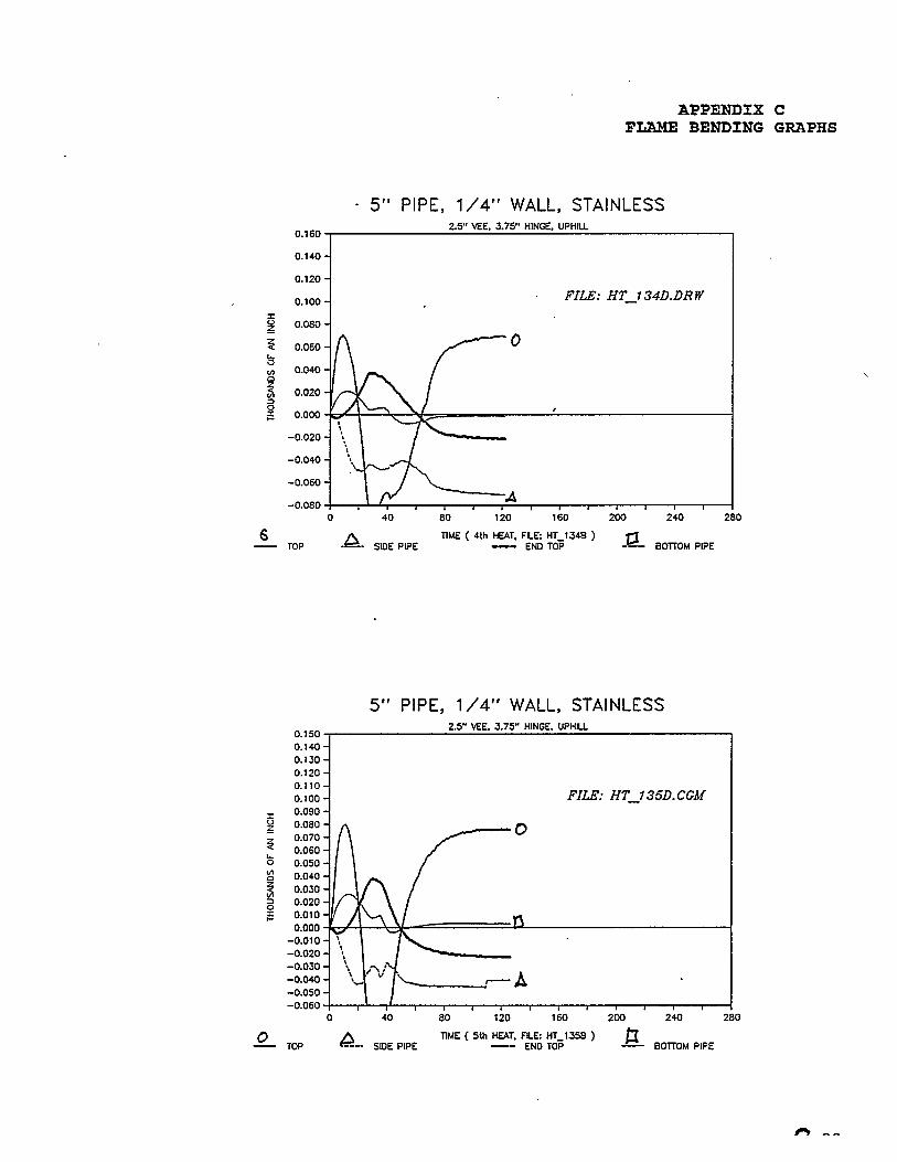
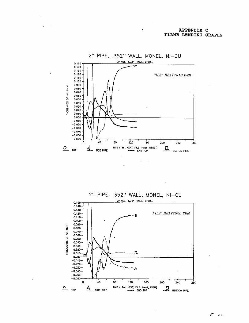
4.2.2 Effects of Multiple Heats
This series of heats show four (4) different materials with three (3different pipe diameters.ALL of these tests share a common vee size to hinge size ratio. A l ltests were made with a 30° vee and a corresponding hinge. Maintain- ing this ratio produces pipe movements with similar values. Thismeans that the shop can predict pipe movement with a reasonabledegree of certainty. The pipe range on which we now have data isfrom 2" to 8" diameter with Carbon Steel, Stainless Steel, 70-30Copper Nickel and 90-10 Nickel Copper.As the vee size to hinge ratio is changed "then the average groupheights will change.
4.2.3 Temperature Measurement TechniquesLine heats were monitored for maximum temperature using the samemethod as was used for the vee heats.
33
FLAME BENDINFINAL REPOR
4.3 Mechanical &
One of the major
Metallurgical
objectives of
Testing
this program was to determine how mechanical and metallurgical properties are affected by the flame bending process.A simple method was used to verify and compare mechanical and metallur-gical properties. The method involved selecting pipe specimens from thtest matrix which received high heat. The maximum peak temperature wasrecorded on each test pipe. This recorded test temperature data wasused to select the pipe for mechanical and metallurgical tests:
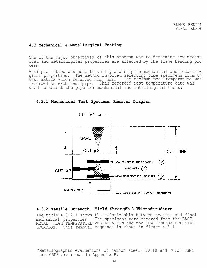
4.3.1 Mechanical Test Specimen Removal Diagram
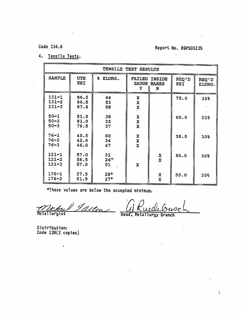
4.3.2 Tensile Strength,The table 4.3.2.1 showsmechanical properties.METAL, HIGH TEMPERATURELOCATION. This removal
Yield Strength & Microstructurethe relationship between heating and finalThe specimens were removed from the BASEVEE LOCATION and the LOW TEMPERATURE STARTsequence is shown in figure 4.3.1.
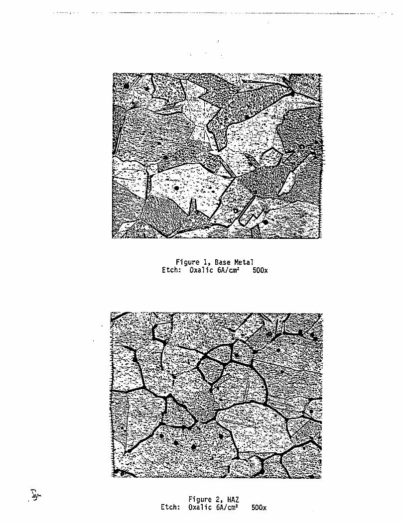
*Metallographic evaluations of carbon steel, 90:10 and 70:30 CuNiand CRES are shown in Appendix B.
34
FLAME BENDINGFINAL REPORT
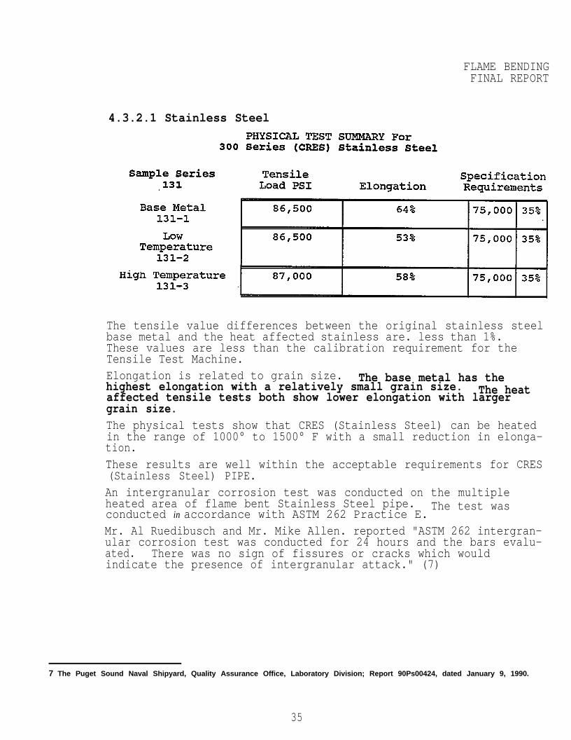
4.3.2.1 Stainless Steel
The tensile value differences between the original stainless steelbase metal and the heat affected stainless are. less than 1%.These values are less than the calibration requirement for theTensile Test Machine.Elongation is related to grain size. The base metal has thehighest elongation with a relatively small grain size. The heataffected tensile tests both show lower elongation with largergrain size.The physical tests show that CRES (Stainless Steel) can be heatedin the range of 1000° to 1500° F with a small reduction in elonga-tion.These results are well within the acceptable requirements for CRES(Stainless Steel) PIPE.An intergranular corrosion test was conducted on the multipleheated area of flame bent Stainless Steel pipe. The test wasconducted in accordance with ASTM 262 Practice E.Mr. Al Ruedibusch and Mr. Mike Allen. reported "ASTM 262 intergran-ular corrosion test was conducted for 24 hours and the bars evalu-ated. There was no sign of fissures or cracks which wouldindicate the presence of intergranular attack." (7)
7 The Puget Sound Naval Shipyard, Quality Assurance Office, Laboratory Division; Report 90Ps00424, dated January 9, 1990.
35
FLAME BENDINGFINAL REPORT
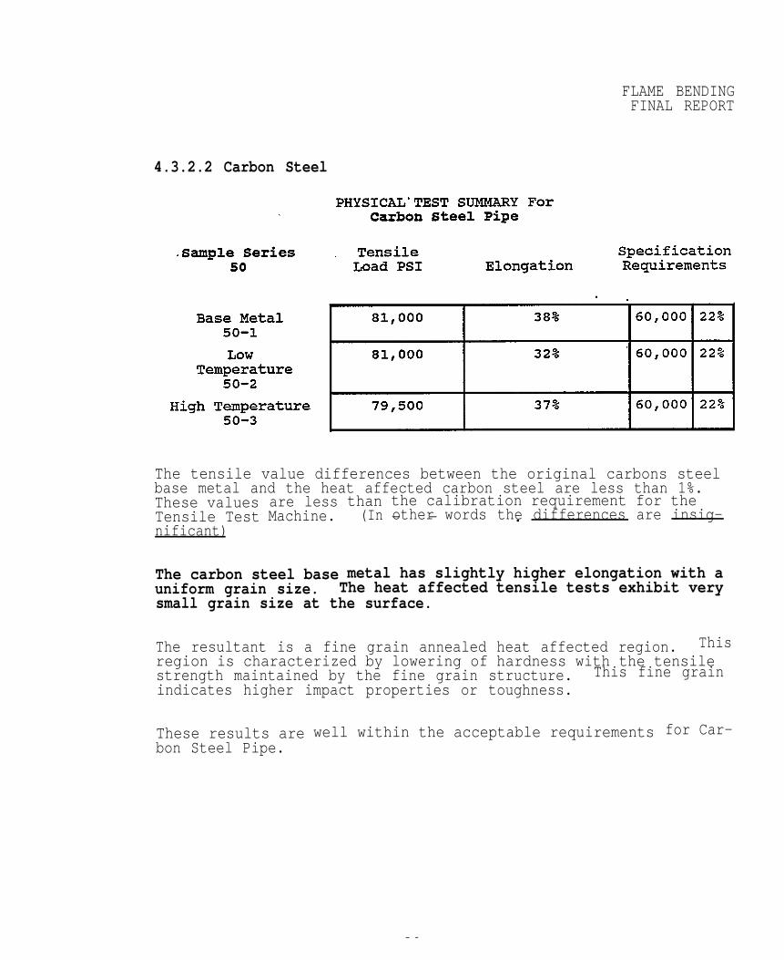
4.3.2.2 Carbon Steel
The tensile value differences between the original carbons steel base metal and the heat affected carbon steel are less than 1%.These valuesTensile Testnificant)
are lessMachine.
than(In
the calibration requirement for theother words the differences are insig-— — .
The carbon steel base metal has slightly higher elongation with auniform grain size. The heat affected tensile tests exhibit verysmall grain size at the surface.
The resultant is a fine grain annealed heat affected region. Thisregion is characterized by lowering of hardness with the tensilestrength maintained by the fine grain structure. This fine grainindicates higher impact properties or toughness.
These results arebon Steel Pipe.
well within the acceptable requirements for Car-
36
FLAME BENDINGFINAL REPOR
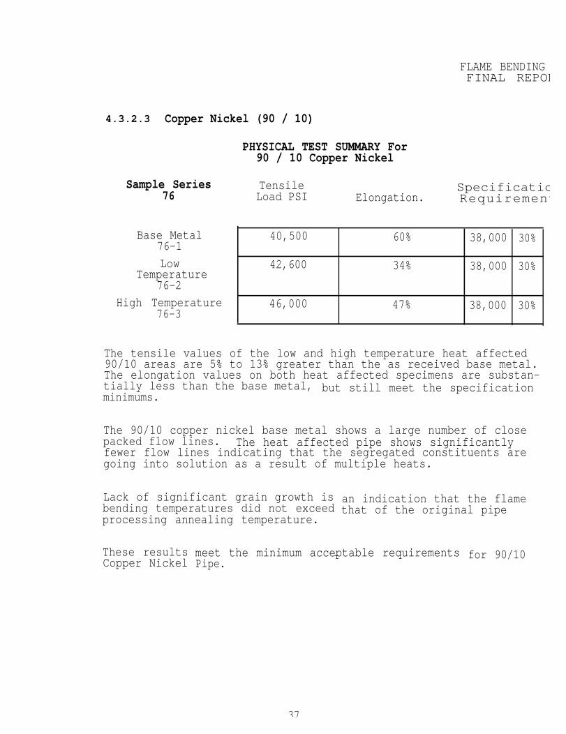
4.3.2.3 Copper Nickel (90 / 10)
PHYSICAL TEST SUMMARY For90 / 10 Copper Nickel
Sample Series Tensile Specificatio76 Load PSI Elongation. Requirement
Base Metal 40,500 60% 38,000 30%76-1
Low 42,600 34% 38,000 30%Temperature
76-2
High Temperature 46,000 47% 38,000 30%76-3
The tensile values of the low and high temperature heat affected90/10 areas are 5% to 13% greater than the as received base metal.The elongation values on both heat affected specimens are substan-tially less than the base metal, but still meet the specificationminimums.
The 90/10 copper nickel base metal shows a large number of closepacked flow lines. The heat affected pipe shows significantlyfewer flow lines indicating that the segregated constituents aregoing into solution as a result of multiple heats.
Lack of significant grain growth isbending temperatures did not exceedprocessing annealing temperature.
an indication that the flamethat of the original pipe
These resultsCopper Nickel
meet the minimum acceptable requirementsPipe.
— for 90/10
37
FLAME BENDINGFINAL REPORT
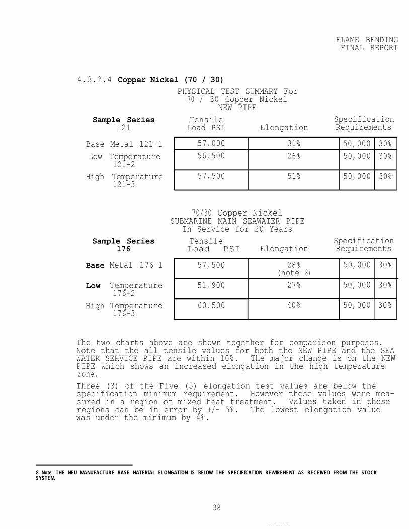
4.3.2.4 Copper Nickel (70 / 30)PHYSICAL TEST SUMMARY For
70 / 30 Copper NickelNEW PIPE
Sample Series Tensile121 Load PSI
Base Metal 121-l
Low Temperature121-2
High Temperature121-3
57,000 31% 50,000 30%56,500 26% 50,000 30%
57,500 51% 50,000 30%
Sample Series Tensile176 Load PSI
Base Metal 176-l
Low Temperature176-2
High Temperature176-3
ElongationSpecificationRequirements
70/30 Copper NickelSUBMARINE MAIN SEAWATER PIPE
In Service for 20 YearsSpecification
Elongation Requirements
57,500
51,900
28%(note 8)
27%
50,000 30%
50,000 30%
60,500 40% 50,000 30%
The two charts above are shown together for comparison purposes.Note that the all tensile values for both the NEW PIPE and the SEAWATER SERVICE PIPE are within 10%. The major change is on the NEWPIPE which shows an increased elongation in the high temperaturezone.Three (3) of the Five (5) elongation test values are below thespecification minimum requirement. However these values were mea-sured in a region of mixed heat treatment. Values taken in theseregions can be in error by +/- 5%. The lowest elongation valuewas under the minimum by 4%.
8 Note: THE NEU MANUFACTURE BASE HATERIAL ELONGATION IS BELOW THE SPECIFICATION REWIREHENT AS RECEIVED FROM THE STOCKSYSTEM.
38
FLAME BENDINGFINAL REPORT
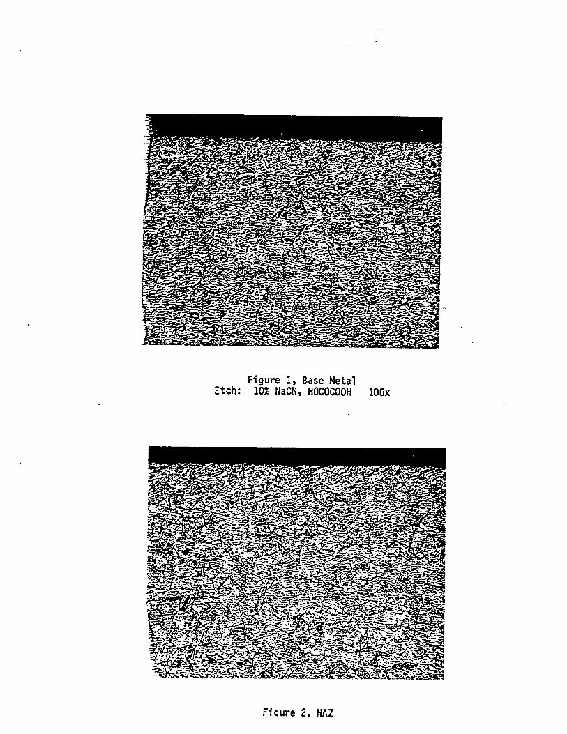
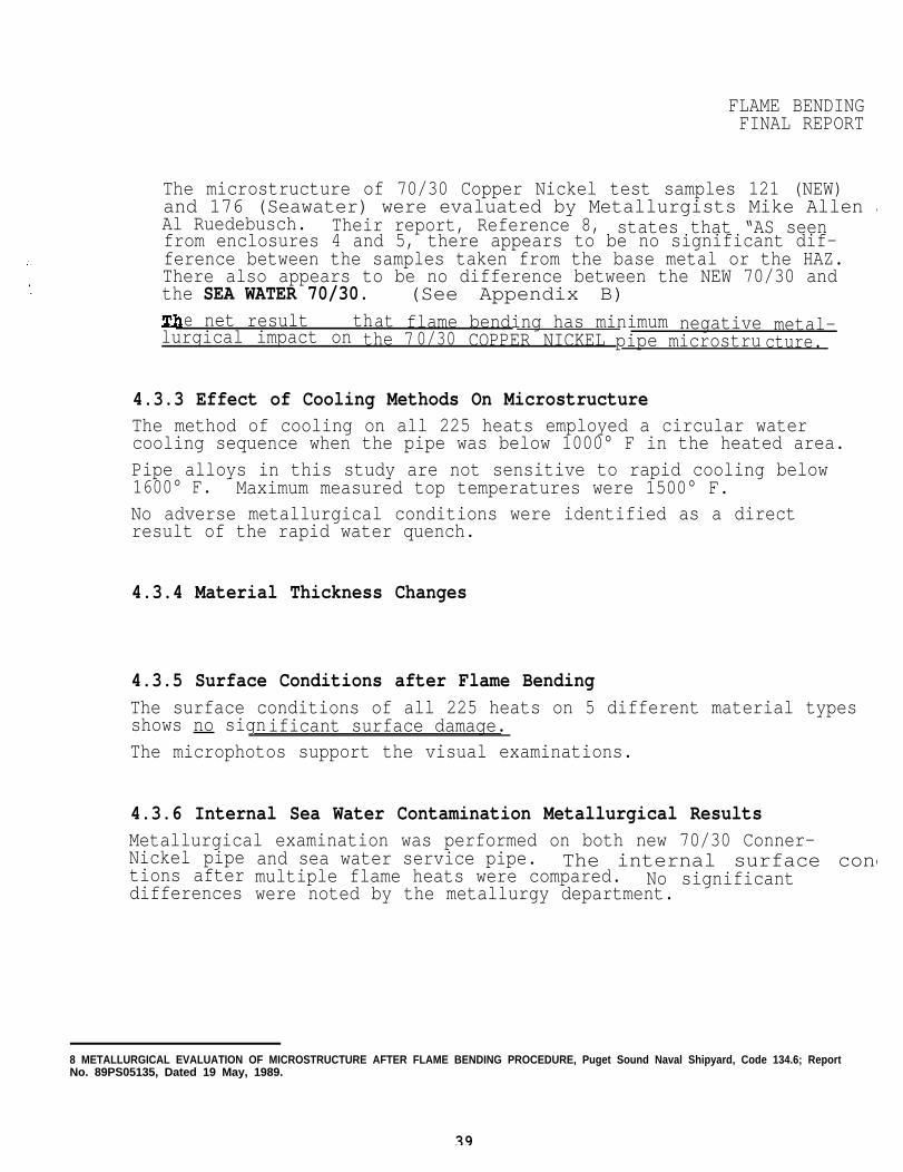
The microstructure of 70/30 Copper Nickel test samples 121 (NEW)and 176 (Seawater) were evaluated by Metallurgists Mike Allen aAl Ruedebusch. Their report, Reference 8, states that “AS seenfrom enclosures 4 and 5, there appears to be no significant dif-ference between the samples taken from the base metal or the HAZ.There also appears to be no difference between the NEW 70/30 andthe SEA WATER 70/30. (See Appendix B)
e net result that flame bending has minimum negative metal-lurgical impact on the 70/30 COPPER NICKEL pipe microstru cture.
4.3.3 Effect of Cooling Methods On MicrostructureThe method of cooling on all 225 heats employed a circular watercooling sequence when the pipe was below 1000° F in the heated area.Pipe alloys in this study are not sensitive to rapid cooling below1600° F. Maximum measured top temperatures were 1500° F.No adverse metallurgical conditions were identified as a directresult of the rapid water quench.
4.3.4 Material Thickness Changes
4.3.5 Surface Conditions after Flame BendingThe surface conditions of all 225 heats on 5 different material typesshows no significant surface damage.The microphotos support the visual examinations.
4.3.6 Internal Sea Water Contamination Metallurgical ResultsMetallurgical examination was performed on both new 70/30 Conner-Nickel pipetions afterdifferences
and sea water service pipe. The internal surface condmultiple flame heats were compared. No significantwere noted by the metallurgy department.
8 METALLURGICAL EVALUATION OF MICROSTRUCTURE AFTER FLAME BENDING PROCEDURE, Puget Sound Naval Shipyard, Code 134.6; ReportNo. 89PS05135, Dated 19 May, 1989.
39
FLAME BENDINGFINAL REPORT
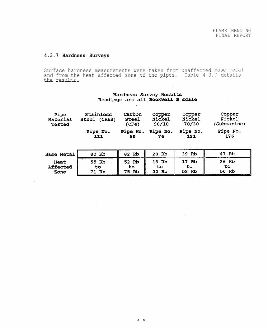
4.3.7 Hardness Surveys
Surface hardness measurements were taken from unaffected base metaland from the heatthe results.
affected zone of the pipes. Table 4.3.7 details
4 0
5
FLAME BENDINGFINAL REPORT
Future Work
5.1 Write Shop Working InstructionThe shop working instruction should be a document which is no longerthan about 25 pages.
5.2 Develop Operator Qualification ProcedureOperator qualification procedures can be written from the engineeringreport in cooperation with shop 56.
5.3 Cooling MethodsOnly one method was used on the 225 tests of this study. The methodthat was used in this work closely matches the method used by PugetSound Naval Shipyard.
5.4 Effects of External RestraintThe experimental work did not cover the effects of external restraint onpipe bending.
5.5 Low Temperature Flame BendingRichard E. Holt determined that the idealmost structural alloys is in the range ofWork needs to be performed to verify thatpipe materials.
5.6 Thickening in the Flame Bent AreaMore accurate values of thickening should
flame bending temperature for700 degrees F.low temperatures will work for
be made in the hot region.
5.7 Charpy Impact ValuesLimitedwork has shown impacts are improved on some materials but addtional work needs to be performed on a broad range of naval materia
FLAME! BENDINGFINAL REPORT
6 CONCLUSIONS
6.1 PreciseA method of
& Simple Torch Calibrationoxyacetylene torch heat calibration has been developed using
precision flow meters and test ring.
6.2 Vee Heating Pattern VS Line Heating PatternsVee heats are more predictable for smaller diameter pipe in the range of2" diameter to 8" diameter. Vee heats should be used as a first choiceby the shop.The majority of-naval and commercial shipyard pipe flame bending can beperformed using 3" VEE HEATS. This VEE size will produce significantdeflection with minimum buckling.
6.3 Line Heats on Large and/or Thin Wall PipeLine heats were found to be more controllable on pipe diameters largerthan 10 inches. Pipe with very thin wall in relation to its diametershould be flame bent using the line heat method.Line heats with a given surface heated area produce greater deflectionthan the equivalent vee heat with the same heated surface area.
6.4 Dimensionless Ratio for Hinge / Vee AreaThere is a relationship between the hinge length and total surface areaof the vee heat. When the above two values yield a number from .005 to03 then the mechanic can assume that each heat sequence will deflect
the pipe the same amount on each heat.
R -CHingeLength)
CTotaLVeeArsa)
The mechanic can reheat pipeobtain predictable movement.
material in the same area repeatedly and
6.5 Ideal Travel SpeedThe ideal travel speed for most small diameter flame bending applicationis in the range from 1.5 to 3.5 ipm.
42
FLAME BENDINGFINAL REPORT
6.6 Maximum Number of Heats on the Same AreaIt has been determined by experimentation that no more than three (3)heats should be applied to the same area. This maximum is not a metal-lurgical limit but is determined by the pipe materials tendency tobuckle after the third heat.
6.7 Pipe Movement On Carbon SteelCarbon steel moves approximately the same amount (with a given heatedarea) each time it is heated in the same location.
6.8 Stainless SteelThe physical tests show that CRES (Stainless Steel) can be heated in therange of 1000° to 1500° F with a small reduction in elongation andlimited metallurgical damage. ASTM 262 intergranular corrosion testswere conducted with no sign of fissures or cracks.
6.9 Carbon Steel Metallurgical Property ImprovementCarbon steel showed generally improved overall physical properties.
6.10 Copper Nickel Metallurgical Properties after Flame BendingFlame bending produces minimum metallurgical damage on the 70/30 COPPERNICKEL pipe microstructure.
6.11 Effect of Flame Bending on Sea Water PipeThere is no measurable metallurgical or mechanical property differencebetween the NEW 70/30 and the SEA WATER CONTAMINATED 70/30 as a resultof flame bending.There is a slight reduction in Tensile, Yield strength and elongation onboth
6.12Each
new and sea water flame bent pipe: The reduction is less than 1%.
Dye Penetrant Testingmaterial type was PT tested after five heats and no evidence of
cracking was found on any of the material tested.
43
FLAME BENDINGFINAL REPORT
6.13 Scaling and Flaking (internal)90/10 copper nickel shows measurable internal scaling and flaking after
flame bending. It is recommended that flame bending on 90/10 not beperformed unless purged during bending or flushed after bending. Thisshould apply to all FEMA and hydraulic piping.All other materials tested showed discoloration but did not scale.
6.14 Flow Meter CalibrationA flow meter may be substituted as the primary calibration method oncethe initial ring/flame length calibration is performed. Individual flowmeters will significantly reduce out of balance heat input.
6.15 Larger Hinge LengthsTests show that larger hinge lengths in the range of 4" to 5" on 5" to8" pipe yield controllable deflections. Current methods use 2" hingelengths which are too small for most applications.
6.16 Optimum Average Vee and Hinge RatiosMost shop work can be accomplished with a 30° vee angle and hinge whichis 1/4 or (25%) of the circumference:
6.17 When to Use Longer HingesLonger hinges should be used when pipe shortening must be held to aminimum.
6.18 Sea Water Pipe Bends70/30 sea water pipe was tested using a standard AWS B4.O-77 guided bendtest. There was no indication of cracking. Dye penetrant tests on thismaterial before bending showed no indications.
6.19 Trained MechanicsDo not use personnel who have no formal flame bending training. Opera-tors should train on similar grades, diameters and wall thicknesses.
44
FLAME BENDINGFINAL REPOR
6.20 Flame Bending of Stainless Steel (CRES)Based on the test work Stainless steel can be flame bent with no signif-icant loss of mechanical or metallurgical properties.
45
APPENDIX A
CODAS Calibration Data Gathering Method
To start Data Gathering to Hard Disk A-1
To stop Data Gathering to Hard Disk A-1
To Display Data Gathering during Flame Bending Test A-1
To Display the eight (8) Data Screen A-1, A-2
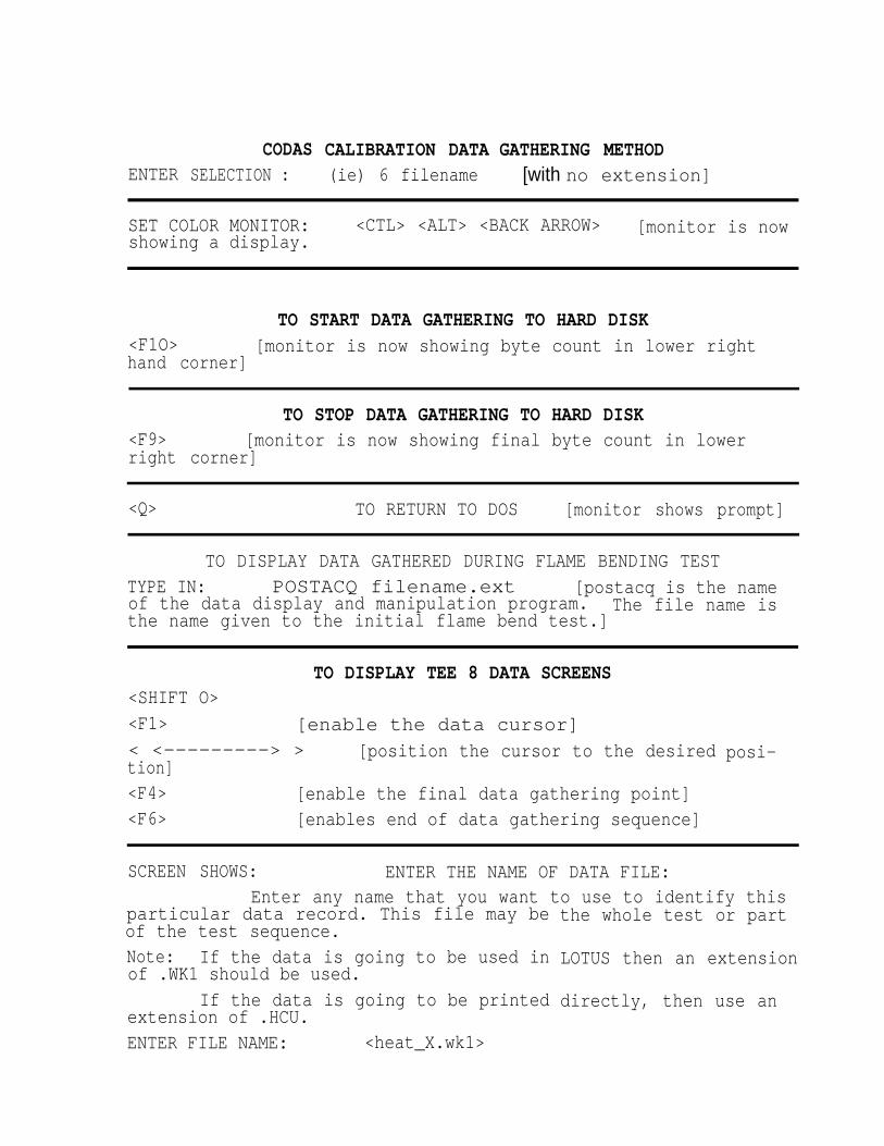
ENTERCODAS
SELECTION :CALIBRATION DATA(ie) 6 filename
GATHERING METHOD[with no extension]
SET COLOR MONITOR:showing a display.
<CTL> <ALT> <BACK ARROW> [monitor is now
TO START DATA GATHERING TO HARD DISK<F1O> [monitor is now showing byte count in lower righthand corner]
TO STOP DATA GATHERING TO HARD DISK<F9> [monitor is now showing final byte count in lowerright corner]
<Q> TO RETURN TO DOS [monitor shows prompt]
TO DISPLAY DATA GATHERED DURING FLAME BENDING TESTTYPE IN: POSTACQ filename.ext [postacq is the nameof the data display and manipulation program. The file name isthe name given to the initial flame bend test.]
TO DISPLAY TEE 8 DATA SCREENS<SHIFT O><F1> [enable the data cursor] < <---------> > [position the cursor to the desiredtion]<F4> [enable the final data gathering point]<F6> [enables end of data gathering sequence]
posi-
SCREEN SHOWS: ENTER THE NAME OF DATA FILE:Enter any name that you want to use to identify this
particular data record. This file may beof the test sequence.Note: If the data is going to be used inof .WK1 should be used.
If the data is going to be printedextension of .HCU.ENTER FILE NAME: <heat_X.wk1>
the whole test or part
LOTUS then an extension
directly, then use an
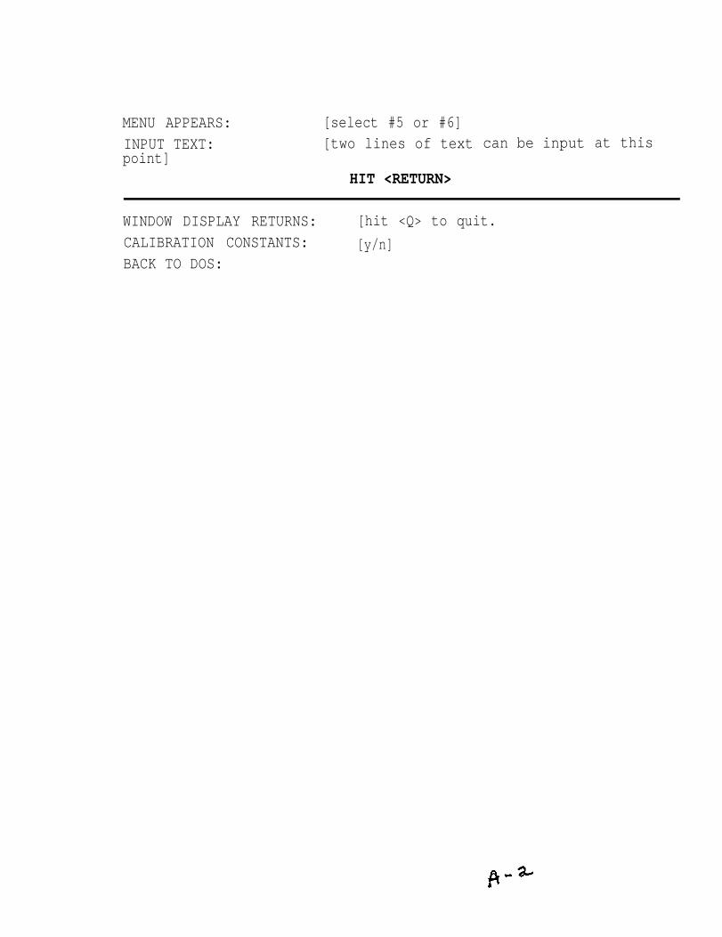
MENU APPEARS: [select #5 or #6]INPUT TEXT: [two lines of textpoint]
HIT <RETURN>
can be input at this
WINDOW DISPLAY RETURNS: [hit <Q> to quit.CALIBRATION CONSTANTS: [y/n]BACK TO DOS:
PUGET SOUND NAVAL SHIPYARDQUALITY ASSURANCE OFFICE
Laboratory Division19 May 1989
Code 134.6 MFA:lms
Metallurgy Branch Report No. 89PS05135
Subj: METALLURGICAL EVALUATION OF MICROSTRUCTURE AFTER FLAME BENDINGPROCEDURE
Ref: (a) American Society for Testing and Materials, Annual Book of ASTMStandards, Volume 1.05, Designation A 262-86, 1987
Encl: (1) Photomicrographs of Pipe 131(2) Photomicrographs of Pipe 50(3) Photomicrographs of Pipe 76(4) Photomicrographs of Pipe 121(5) Photomicrographs of Pipe 176
1. Five samples were provided by Code 138 for hardness testing and evaluationof the microstructure. The samples were taken from sections of pipe that hadbeen cycled through a flame bending procedure. The cycle consisted of heatingfrom room temperature to approximately 1500°F and then water quenching. Therewere a total of five cycles.
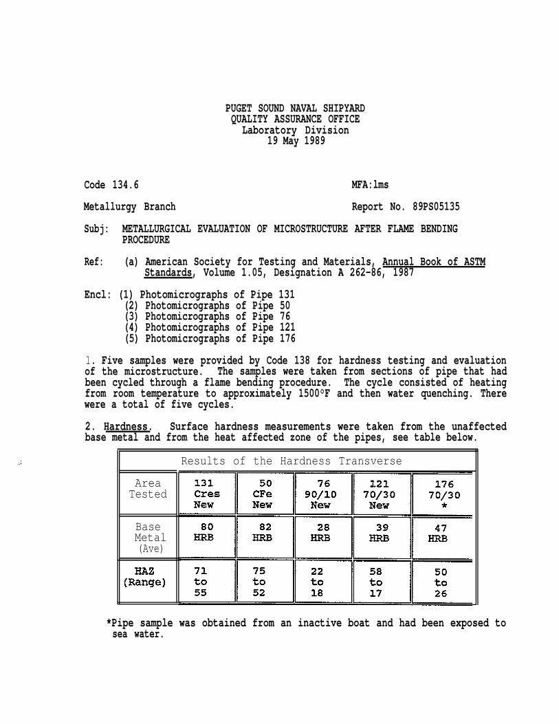
2. Hardness. Surface hardness measurements were taken from the unaffectedbase metal and from the heat affected zone of the pipes, see table below.
AreaTested
BaseMetal(Ave)
Results of the Hardness Transverse
*Pipe sample was obtained from an inactive boat and had been exposed tosea water.
Code 134.6 Report No. 89PS05135
3. Microstructure. Two samples were sectioned from each pipe to determinewhat effects the flame bending procedure had on the microstructure, if any.One sample was taken from the base metal and one from the heat affected zone.
Pipe 131:
Due to stainless steel’s susceptibility to sensitization, an oxalicacid etch test was performed on this sample. ASTM Standard A 262, Practice A,was used to determine what degree of sensitization the flame bending procedureproduced in the steel. As seen in enclosure (l), there is a differencebetween the sample from the HAZ and the base metal. The base metals figure 1,shows a step structure while the sample from the HAZ, figure 2, has a dualstructure with some ditching. This indicates that there is some sensitizationwhich increases its susceptibility to intergranular attack. While Practice Acannot be used to reject the material, it does show that more testing isrequired.
hashashas
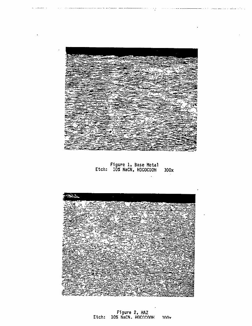
Pipe 50:
Enclosure 2, figures 1 and 29 shows that the flame bending Procedurea recrystallization effect on the carbon steel. The sample from the HAZsmaller grains near the surface, whereas the sample from the base metaluniform grain size throughout.
Pipe 76:
The flame bending cycle, for the 90/10, appears to alter the flowpattern of the material. As seen in enclosure (3), figure 1, there are alarge number of flow lines present in the base metal sample. Figure 2 is fromthe HAZ and the number of flow lines have been significantly reduced. Thereis no indication of recrystal-lization-or grain growth.
Pipes 176 and 121:
As seen from enclosures 4 and 53 there appears to be nO significantdifference between the samples taken from the base metal or the HAZ. Therealso appears to be no difference between the new 70/30 and the sea water70/30.