npstc presentation revised • kenwood goes by “nexedge ... similar performance is stated for...
TRANSCRIPT

NXDN™
NXDN is a trademark of Icom Incorporated and Kenwood Corporation

• Icom Digital Advance System • Pronounced “eye-duss” • System name given to Icom products that are
compatible with the NXDN™ protocol • Kenwood goes by “NEXEDGE” • Robust Analog Feature Set
– Not to be forgotten in the IDAS discussions today
• Digital Feature Set Finalized – Over 2 years on the market
IDAS in General

• Regulatory History – Re-farming in 1995 – March 2007 Report and Order
• Icom’s Role in 6.25 kHz Development – February 2005 Joint Development Agreement with Kenwood – $10M US Stock Swap
• Product History – March 2005: First NXDN™ Compatible Portable Radio – March 2006: First NXDN™ Compatible Mobile Radio – January 2008: 2nd Generation IDAS Portable – February 2008: FR5000 Series IDAS Repeaters
NXDN™ Development Overview

• Partner Expansion – Icom Japan and Kenwood Japan initial partners – This has now expanded to include not only Icom America and
Kenwood USA, but Daniels, Ritron, Trident Micro Systems and Aeroflex as well
NXDN™ Overview Continued

FCC Report And Order - 3/22/07
• "FCC...strongly urges licensees to consider migrating directly to 6.25 kHz technology rather than first adopting 12.5 kHz technology and later migrating to 6.25 kHz technology."
• "The FCC reiterated, however, that it will expeditiously establish a schedule for transition to 6.25 kHz narrowband technology once the technology matures to the point that sufficient equipment is available for testing."
• "Deferring the implementation date permits manufacturers to develop and test equipment after the expected finalization of 6.25 kHz standards in the near future."

FCC Report And Order - 5/12/08
• We are aware that many licensees .. have already commenced the transition to 12.5 kHz technology in order to comply with the 2013 deadline. We applaud these efforts, and do not believe that they should be suspended or abandoned.
• … Third Report and Order urging licensees to consider migrating directly to 6.25 kHz technology was not intended to dissuade migration to 12.5 kHz technology by licensees that have already begun the process.

FCC Report And Order - 5/12/08
• We reiterate, however, that 12.5 kHz technology is a transitional step in the eventual migration of PLMR systems to 6.25 kHz technology. As the demand for scarce PLMR spectrum continues to grow, the Commission will closely monitor the progress made by standards-setting

• Regulatory • Improved voice information transfer at range
– Demonstrated better performance in multi-path conditions – Lack of “white noise” and static reduces operator fatigue
• Digital features – Digital provides better integration of signaling features than
analog – Digital provides new features not available in analog – 800-950 BPS control data
• NEMA GPS compatibility • Transport latitude, longitude etc. • Limited telemetry
4 Main Benefits using 6.25 NXDN™ Technology

• Digital features Continued – Use entire 6.25 for data
• Significantly better spectrum efficiency – On VHF, 6.25kHz eliminates geographic separation on 7.5kHz
channel centers – Space every 7.5 kHz – On UHF, space every 6.25 kHz
Benefits - Continued

• IDAS uses existing one signal/one voice path paradigm – No “repeater-less” complications – Site failure only brings down one channel
• Full backward analog compatibility and mix-mode makes transition to digital an orderly event
• Uses existing FM hardware – Simple to use – Easy to repair – More affordable components
• Backwards compatible – Easily merges into existing fleets
IDAS Highlights

• DTMF Tones will pass through 6.25 NXDN™ in limited testing • In voting systems, comparators need to work on BER rather
than SINAD. This should also be studied.
• Tonal quality of voice is slightly altered – This can be worked with through operator training
• Agreement about how to handle answer back in Mixed Mode
IDAS Transition Challenges - General

Band Plan “Ready for 6.25 kHz” in VHF

Band Plan “Ready for 6.25 kHz” in UHF

Choosing the Right Platform
• When considering a radio platform, you need to consider both current and future needs: – Robust, feature rich analog radios – Narrow band digital radios with enhanced feature sets

Digital Features
• PTT ID • Alias Table • Call Log • Call Alert • Radio Check • Stun • Kill • Revive • Remote Monitor
• Select Call • Group Call • Man Down (F3161
Series) • Emergency Call • Status Message • Short (fixed) Message • PC remote control • Mixed Mode • Encryption (15 bit) • GPS

6.25 NXDN™
• Next Generation Digital Narrowband

How 6.25 NXDN™ Works

6.25kHz NXDN Emission Designator
• 4K00F1E, Voice (for when the use is primarily for voice information)
• 4K00F1D, Digital (for when the use is primarily for data information)

AMBE+2 versus IMBE
• Half-rate of IMBE • Superior Voice Quality/Performance
Vocoder processing A/D
D/A VCO PLL
A/D: Analog to Digital Converter D/A: Digital to Analog Converter FEC: Forward Error Correction
MIC
FEC coding
& Frame
structure
Frame Sync
Control data
4-level FSK
Signal Bandwidth
limiting filter
2-level ↓
4-level
2,400sps 4,800bps
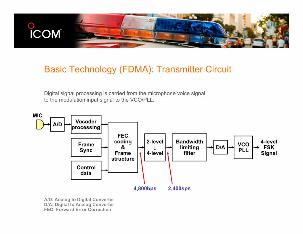
Digital signal processing is carried from the microphone voice signal to the modulation input signal to the VCO/PLL.
Basic Technology (FDMA): Transmitter Circuit

• Transfer Rate: 4,800 bps (2,400 symbol per sec.)
Symbol Mapping


FM detection A/D Sync
Processing
D/A 4-level
judgment
Bandwidth limiting
filter
4-level ↓
2-level
Vocoder processing
Control data
FEC coding& Frame Break-down
SP
4-level FSK
Signal
2,400sps 4,800bps
Digital signal processing is carried from the FM detector output signal to the speaker voice signal
Basic Technology (FDMA): Receiver Circuit

Conventional System
• 16 bit Unit ID, uniquely definable for each system – Identifiable approx. 65,000 units per 1 system
• 16 bit Group ID, uniquely definable for each system – Identifiable approx. 65,000 groups per 1 system
• 6 bit Radio Access Number (RAN) – CTCSS/CDCSS like operation
• Similar operation to an analog system possible – Group call using only RAN (CTCSS/CDCSS like) – Selective call using RAN and Unit/Group ID (CTCSS + DTMF
like)
• Even if in Selective Call, Late Entry function works

Channel Parameters
• Single Data Rate and Single Channel Bandwidth – 4800bps, 6.25kHz BW
• Parameters for 6.25kHz Channel (Mask E) – Channel Access FDMA/SCPC – Vocoder AMBE+2tm – Modulation 4 Level FSK – TX BB Filter Root Raised Cosine + sinc – RX BB Filter Root Raised Cosine + 1/sinc – Data Rate 4800bps – Frame Length 80ms – Deviation ±1050Hz@±3symbol、±350Hz@±1symbol

The diagram below shows the basic frame structure of the CAI.
• Made up from Frame Sync, Control data and Voice data
• User data can be included
• Transfer data together with voice data
Frame Sync Area
Control Data Area
Voice Data Area
Common Air Interface (CAI)

The bandwidth measurements below show the 6.25kHz FDMA signal meets the FCC designated emission mask requirements.
6.25 kHz channel
Basic Technology (FDMA): Emission Mask

2 6,25 NXDN™ Signals at 7.5 kHz Separation

2 6,25 NXDN™ Signals at 6.25 kHz Separation

Icom IDAS Capable Products, Specifications and Features

Features – IDAS F3161 portable and IDAS F5061 mobile are cousins
• 3-in-1 Platforms - Analog, Digital, Trunking in the same radio • 512 Channel Capacity • Uses same programming (cloning) software • 2.5kHz, 3.125kHz PLL channel steps • -22F to +140F Usable temperature range

F3161 Portable – one radio, many applications
• 14 Hour Battery Life – @5/5/90 duty cycle – 2000 mAH Li-Ion – Industry Standard low battery alert
tones • Durability
– Aluminum die-cast frame and polycarbonate casing
– Mil-Std 810E – IP54/55 dust, splash, and water jet
resistance – Rugged dual-rail guide securely locks
the battery to the radio
• Full Dot-Matrix Display – Selectable from 1 line, 12 character;
or 2 line, 24 character – Bottom row shows assigned
functions [P0] to [P3] • Enhanced Audio
– BTL Amplifier increases audio output
– Built-in compander provides clear, low noise communications

F3161 Portable – one radio, many applications
• Specifications – Transmitter:
• +/-1ppm stability • 75dB Spurious Emissions • 80dB Adjacent channel power
(25kHz) • 46dB FM Hum and Noise (25kHz)
– Receiver: • 75dB Adjacent Channel (25kHz) • 70dB Spurious Response • 74dB Inter-modulation

F5061 Mobile – one radio, many applications
• 5-50W adjustable power output • Excellent Receiver Specifications
– 85dB Adjacent Channel (25kHz) – 90dB Spurious Response – 77dB Inter-modulation
• Front Firing Speaker = Loud Audio, may not require external speaker
• Splash and Dust Resistant – IP54/55 Compliant – “Ingress Protection” rated as
resistant to dust and low pressure water jet
• +/-1ppm stability - Use as inexpensive base station/repeater

F5061 Mobile – one radio, many applications
• 25 Pin Connector and “coffee beans” – Too detailed for this discussion – Specific information available on KB

FR5000 Base Station/Repeater
• Designed from scratch as a base/repeater, not based on mobiles
• Available mid 2008, samples well before then
• Supports 25kHz and 12.5kHz Analog, and 6.25kHz NXDN™
• 50 watts, 25 watt continuous duty • 19” rack mount • 220/110VAC, 12VDC, Battery Back Up
Ready • Slide in networking card for IP expansion

IDAS
• LTR-like digital trunking system in summer ’08 • Both 3161 and 5061 can be upgraded to digital trunking by
upgrading firmware

Future System Possibilities

NXDN in the real world

FDMA achieves the same or better audio coverage than analog FM at distance. Similar performance is stated for MOTOTRBO (TDMA) products.
Distance
Audio Quality
Analog 4L FSK/FDMA
Basic Technology: Analog vs Digital Coverage

Coordinating NXDN™
Icom’s Findings

The Coordinating Process
As we understand it…

Exclusive Channels
Much of the discussion here will revolve around exclusive channel coordination

Service Area
For the purposes of coordination three different factors are considered
– HAAT (Height Above Average Terrain) – ERP (Effective Radiated Power) – Contour

HAAT
• Way of determining about how high your antenna is ON AVERAGE, in any direction by averaging the terrain to one height
• Take at least 50 samples along each radial (commonly 72) extending from 2 to 10 miles from site
• ComStudy does every 1/10 kilometer
ERP
“Effective Radiated Power” – The amount of RF power coming from the actual antenna of
the transmitter toward the horizon

R-6602(Carey) Contours • Based on averaged (flat) terrain • Service Contour: Approximate area of service for incumbent • Interference Contour: Area where proposed station might interfere with
an incumbent. An interference contour is always be larger than a service contour.
• Currently, coordinators only check to make sure that a proposed licensee’s “Interference Contour” will NOT overlap an incumbent’s service contour.

Contours - Continued • Field strength values for defining a contour are in dBµ (decibels
above 1 µV/meter) • In UHF, for example, the service contour is 39 dBµ. VHF is 37 dBµ. • Also in UHF, for example, the interference contour is 21 dBµ. VHF is
19 dBµ.

Co-Channel & Adjacent
• The previous examples were for the purposes of “Co-Channel” coordination
• A co-channel signal is any signal at the same frequency. Coordinators often considered frequency separations 6.25 kHz (or less) to be the same as co-channel for UHF (7.5 kHz for VHF).
• Adjacent channel signals are considered for coordination also • An adjacent channel signal is any signal within 12.5 kHz of channel
center for UHF and 15 kHz for VHF • Adjacent channel signals are currently “de-rated” 12.5 dB when being
considered

Co-Channel & Adjacent – Proposed for 6.25
• VHF systems will use a 13 dB derating of the interference contour for systems spaced at 7.5 kHz. The service contour is the 37 dBu f(50,50) contour and the interference contour is the 32 dBu f(50,10) contour.
• UHF systems will use an 8 dB derating of the interference contour for systems spaced at 6.25 kHz. The service contour is the 39 dBu f(50,50) contour and the interference contour is the 29 dBu f(50,10) contour.
• The derating factors will be reviewed in 2 years and increased by 3 dB unless interference cases are documented during the review period.
• The criteria is used in both directions; i.e. the interference contour of the proposed system may not overlap the service contour of the incumbent system and the interference contour of the incumbent system may not overlap the service contour of the proposed systems.

Adjacent Channel Example
• With a proposed site, coordinators look at surrounding incumbents up and down from the Proposed Site’s center frequency. If their de-rated service contour does not intersect incumbent site service contour, then coordination can proceed.

Tying HAAT, ERP and Contours Together
• ERP and HAAT both affect the service area radius. If either increases, the radius will increase
• 50, 50 means that 50 percent of receivers will receive the signal 50% of the time based on above ERP/HAAT. It takes more signal for that.
• 50, 10 means that 50 percent of receivers will receive the signal 10% of the time based on above ERP/HAAT. It takes less signal for that.
• Currently, service contours use 50, 50. Interference contours use 50, 10.
Coordination
• If the proposed stations co-channel or adjacent channel interfering contours cross the incumbents service contour, the proposed stations application cannot go forward.
• If they do not, then the proposed station can be coordinated.