nphysics laboratory 10.2: plane, convex, and concave...
TRANSCRIPT

nPhysics Laboratory 10.2: Plane, Convex, and Concave Mirrors
Name: ____________________________________ Date: ________________________
Lab Partners: ____________________________________________________________
PURPOSE: The purpose of this laboratory is to present the rules for locating images
for different types of mirrors and to illustrate their use with examples.
EQUIPMENT: Three Mirrors (plane, convex, concave), Meter Stick, Two Milk
Containers (one to serve as the object and the other as a reference for the images)
THEORY: Certain optical devices (mirrors and lenses) can be used to “create” images of
objects that our brains interpret as actual objects themselves. Mirrors accomplish this by
reflecting light in such a manner that we “see” images in locations that are not actually
occupied by the objects in question, while lenses accomplish this feat by virtue of how
light changes direction when traveling between two materials in which the speed of light
is different. In addition, certain mirrors and lenses can adjust the magnification of the
object for clearer viewing.
Law of Reflection: A light ray incident upon a reflective
surface will be reflected at an angle equal to the incident
angle. Both angles are typically measured with respect to the
normal to the surface.
The Law of reflection is the only thing needed to sketch every single ray diagram, though
it seems more complicated than that given the different possibilities. In order for a mirror
to be effective, it must be shaped properly so that the reflected rays can reach our eyes in a
spatial arrangement that can be properly processed by our brains. The “perfect” shape for
a curved mirror is a paraboloid, although spherical mirrors are also effective.
Plane Mirrors: In the case of a plane mirror, the reflected rays reach our eyes in a pattern
that results in our brain’s concluding that there is second object behind the mirror at
precisely the same distance and size of the object being reflected by the mirror.
Convex Mirrors: A convex mirror is a mirror that bulges in the center. As for the
plane mirror, the image is upright (right side up) and virtual (our brains must project
diverging reflected rays backward to create the image). Unlike the plane mirror, the
image for a convex mirror is always reduced in size as compared to the size of the
associated object.
Concave Mirrors: A concave mirror is a mirror that curves forward at the edges.
When the focal point is between the object and the mirror surface, the resulting image is
inverted, real, and reduced. When the object is between the focal point and the mirror
surface and the resulting image is upright, virtual, and enlarged.
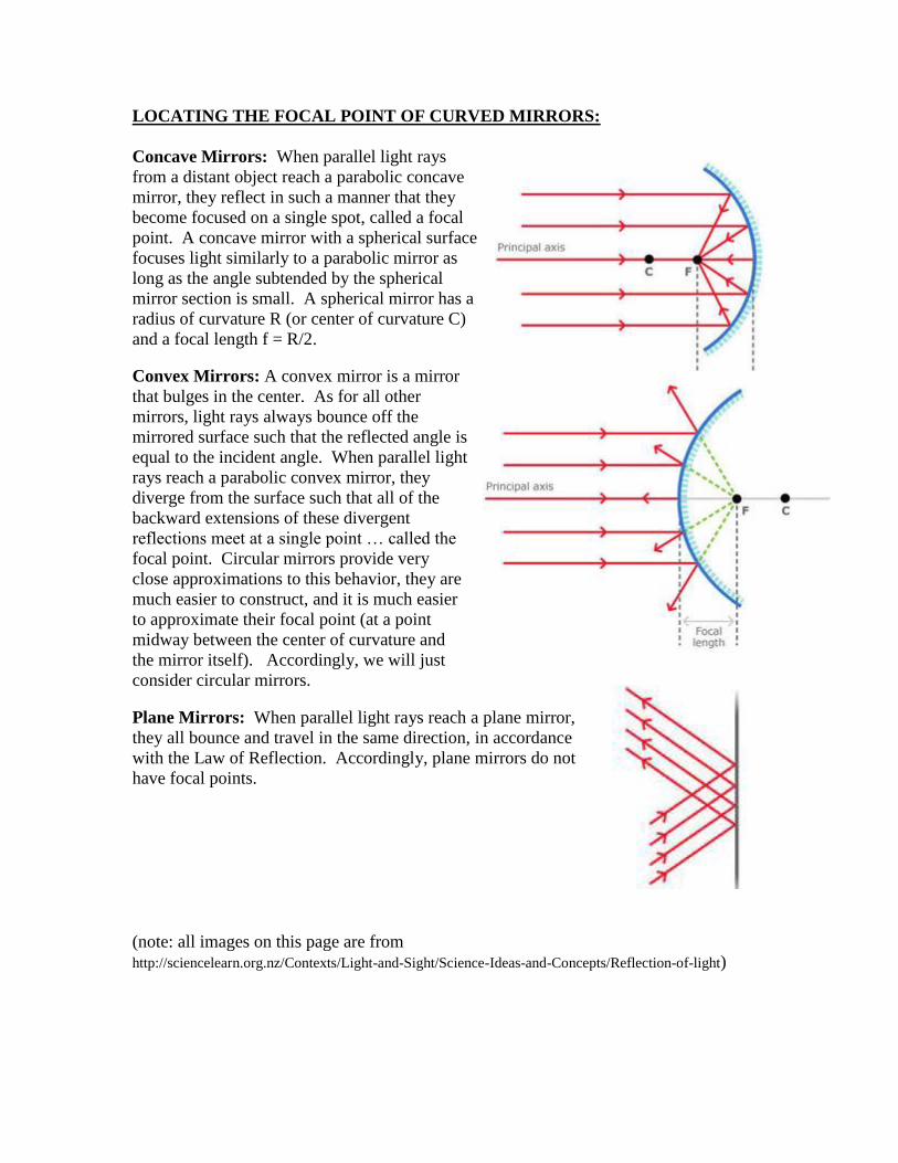
LOCATING THE FOCAL POINT OF CURVED MIRRORS:
Concave Mirrors: When parallel light rays
from a distant object reach a parabolic concave
mirror, they reflect in such a manner that they
become focused on a single spot, called a focal
point. A concave mirror with a spherical surface
focuses light similarly to a parabolic mirror as
long as the angle subtended by the spherical
mirror section is small. A spherical mirror has a
radius of curvature R (or center of curvature C)
and a focal length f = R/2.
Convex Mirrors: A convex mirror is a mirror
that bulges in the center. As for all other
mirrors, light rays always bounce off the
mirrored surface such that the reflected angle is
equal to the incident angle. When parallel light
rays reach a parabolic convex mirror, they
diverge from the surface such that all of the
backward extensions of these divergent
reflections meet at a single point … called the
focal point. Circular mirrors provide very
close approximations to this behavior, they are
much easier to construct, and it is much easier
to approximate their focal point (at a point
midway between the center of curvature and
the mirror itself). Accordingly, we will just
consider circular mirrors.
Plane Mirrors: When parallel light rays reach a plane mirror,
they all bounce and travel in the same direction, in accordance
with the Law of Reflection. Accordingly, plane mirrors do not
have focal points.
(note: all images on this page are from
http://sciencelearn.org.nz/Contexts/Light-and-Sight/Science-Ideas-and-Concepts/Reflection-of-light)

Theory to Practice Demonstrations: For each of the three photographs below,
indicate the type of mirror being used and, where appropriate, locate both the center of
curvature and the focal point.

CREATING IMAGES: The four examples below illustrate the 4 cases for image types
that correspond to the different mirrors. In each case, indicated whether the image is:
upright or inverted, real or virtual, reduced or actual size or magnified.
Description Physical Apparatus Ray Diagram
Plane Mirror
_____________
_____________
_____________
Convex Mirror
_____________
_____________
_____________
Concave Mirror
with focal point
between object
and mirror:
_____________
_____________
_____________
Concave Mirror
with object
between focal
point and mirror
_____________
_____________
_____________

STUDENT PRACTICE: Creating Ray Diagrams to locate images for the 4 cases
Plane Mirrors: Show where the images of the arrows illustrated will be located for the
two plane mirrors illustrated below.
Convex Mirrors: Show where the images of the arrows will be located for the three
convex mirrors shown below:

Concave Mirrors: Show where the images of the arrows will be located for the concave
mirrors illustrated below:

CONSTRUCTION#1: FINDING THE FOCAL POINT FOR A CONCAVE
PARABOLIC MIRROR
Set-Up: (Note: This has already been completed on the figure below)
o Draw the parabola x=4.0-0.25y2 for the range -5.0<y<5.0
o Draw a set of 9 equally spaced horizontal lines, centered around the line y=0.0
and with a separation of 1.0 units in the y-direction
Light Ray Incident @ y=0.0, which is along the principal axis of the mirror:
o Darken the line y=0.0 from the left edge of the figure until it meets the mirror
surface, this represents the incident light ray along the principal axis
o Draw the reflected ray using the law of reflection, based upon the two
associated short line segments, which represent the tangent and perpendicular
directions for the mirror at y=0.0 (Note: From the Law of Reflection, you
should find that the reflected ray travels back along the principal axis of the
mirror)
Light Ray Incident @ y=1.0:
o Darken the line y=1.0 from the left edge of the figure until it meets the mirror
surface, this represents the incident light ray
o Draw the reflected ray using the law of reflection, from the mirror until it
crosses the principal axis. Short line segments, which represent the tangent and
perpendicular directions for the mirror at y=1.0, have already been drawn to
assist in the construction.
Light Rays Incident @ y=2.0, y=3.0, y=4.0, y=-1.0, y=-2.0, y=-3.0, y=-4.0
o Repeat instructions above for Light Ray Incident @ y=1.0
o You should find that all of the reflected rays cross the principal axis of the
mirror at the same point. This is the location of the focal point

CONSTRUCTION#2: FINDING THE FOCAL POINT FOR A CONCAVE
SPHERICAL MIRROR
Set-Up: (Note: This has already been completed on the figure below)
o Draw a right semicircle of radius R=4.0 that is centered at the origin, with the
line y=0.0 separating the upper and lower halves of the semicircle. This
semicircle represents the mirror surface
o Draw a set of 7 equally spaced horizontal lines, centered around the line y=0.0
and with a separation of 1.0 unit in the y-direction
Light Ray Incident @ y=0.0, which is along the principal axis of the mirror:
o Darken the line y=0.0 from the left edge of the figure until it meets the mirror
surface, this represents the incident light ray
o Draw the reflected ray using the law of reflection, based upon the two
associated short line segments, which represent the tangent and perpendicular
directions for the mirror at y=0.0 (Note: From the Law of Reflection, the
reflected ray travels back along the principal axis of the mirror)
Light Ray Incident @ y=1.0:
o Darken the line y=1.0 from the left edge of the figure until it meets the mirror
surface, this represents the incident light ray
o Draw the reflected ray using the law of reflection, from the mirror until it
crosses the principal axis. Short line segments, which represent the tangent and
perpendicular directions for the mirror at y=1.0, have already been drawn to
assist in the construction. (Note: You should find that the x-intercept of the
reflected ray is very close to ½ way between the center of curvature and the
mirror, along the principal axis. This is the focal point for a circular mirror)
Light Rays Incident @ y=2.0, y=3.0, y=-1.0, y=-2.0, y=-3.0
o Repeat instructions above for Light Ray Incident @ y=1.0.
o You should find that the incident rays father from the principal axis result in a
reflected waves that deviate farther from the focal point. This is property of
spherical mirrors is called spherical aberration.

APPENDIX: Detailed steps for creating ray diagrams
CASE#1-PLANE MIRRORS: Creating ray diagrams for a plane mirror
Set Up:
o Draw a plane mirror and an object in front of the mirror surface. o Select a point on the object to analyze.
Locating the Image
o Draw the incident light ray (1) from the selected point that is perpendicular to
the mirror surface. This light ray will just bounce straight back. Draw the
reflected ray.
o Draw an incident light ray (2) from the selected point to another point on the
mirror surface. Draw the reflected ray using the Law of Reflection.
o The intersection of the backward extensions for the (diverging) reflected rays
marks the position of the image for the selected point.
Verifying the location of the image.
o Draw a third incident ray from the selected point and confirm that the backward
projection of its reflected ray passes through the intersection of the first two.
Examples:
The “image” distance behind the mirror is identical to the “object” distance in front of
the mirror. The image is termed “virtual” as the reflected light rays diverge and they
must be projected backwards to find a location where they “meet”. The image is
“upright” as it has the same vertical orientation as the object. The magnification is one
as the image is the same size as the object.

CASE#2-CONVEX MIRRORS: Creating ray diagrams for a convex mirror:
Set-Up:
o Draw the spherical mirror surface of radius R.
o Draw a line from the center point of the mirror such that it passes through
the mirror at its center. This is the principal axis.
o Mark the center of curvature (C … at a distance R behind the mirror
surface) and the focal point (f … half way between the mirror surface and
C) along the principal axis.
o Draw the object in front of the mirror surface.
Locating the image:
o Draw the first incident ray (1) parallel to the principal axis from a point
on the object to the mirror and reflecting from the mirror as though it
originates from the focal point.
o Draw a second incident ray (2) from the same point on the object that is
directed toward the focal point and reflects parallel to the principal axis.
o The intersection of the backward projections of the two reflected rays
marks the location of the image.
Verifying the location of the image:
o Draw a third incident ray (3) from the same point on the object as the first
two, that is directed toward the center of curvature. This ray reflects back
onto itself. The backward projection of this reflected ray should pass
directly through the intersection of the projections of the first two
reflected rays … confirming the location of the image!
The ray diagram below illustrates this procedure for a pencil. An upright, virtual, and
reduced image with always formed for a convex mirror.

CASE#3-CONCAVE MIRRORS: Creating ray diagrams for a concave mirror,
when the focal point is between the object and the mirror surface
Set-Up:
o Draw the spherical mirror surface of radius R.
o Draw a line from the center point of the mirror such that it passes through
the mirror at its center. This is the principal axis.
o Mark the center of curvature (C … at a distance R behind the mirror
surface) and the focal point (f … half way between the mirror surface and
C) along the principal axis.
o Draw the object in front of the mirror surface.
Locating the image:
o Draw the first incident ray (1) parallel to the principal axis from a point
on the object to the mirror and reflecting from the mirror such that it
passes through the focal point.
o Draw a second incident ray (2) from the same point on the object that
passes through the focal point on its way to the mirror surface and
reflects such that it is directed parallel to the principal axis.
o The intersection of the two reflected rays indicates the location of the
image.
Verifying the location of the image:
o Draw a third incident ray (3) from the same point on the object as the first
two, that is directed toward the center of curvature. This ray reflects back
onto itself and should pass directly through the intersection of the first
two reflected rays … confirming the location of the image!
The ray diagram below illustrates this procedure for a pencil. A real, inverted, and
reduced image with always formed when the pencil is beyond the focal point for a
concave mirror.

CASE#4-CONCAVE MIRRORS: Creating ray diagrams for a concave mirror,
when the object is between the focal point and the mirror surface
Set-Up:
o Draw the spherical mirror surface of radius R.
o Draw a line from the center point of the mirror such that it passes through
the mirror at its center. This is the principal axis.
o Mark the center of curvature (C … at a distance R behind the mirror
surface) and the focal point (f … half way between the mirror surface and
C) along the principal axis.
o Draw the object in front of the mirror surface.
Locating the image:
o Draw the first incident ray (1) parallel to the principal axis from a point
on the object to the mirror and reflecting from the mirror such that it
passes through the focal point.
o Draw a second incident ray (2) from the same point on the object that is
directed toward the mirror surface along the line that passes through both
the focal point and the point on the object. This ray will reflect such that
it is directed parallel to the principal axis.
o The intersection of the backward extensions for the (diverging) reflected
rays marks the position of the image.
Verifying the location of the image:
o Draw a third incident ray (3) from the same point on the object as the first
two, that is directed toward the mirror surface along the line that passes
through both the center of curvature and the point on the object. This ray
reflects back onto itself and is also divergent to the first two reflected
rays. The backward projection of the reflected wave and should pass
directly through the image location found earlier … confirming the
location of the image!
The ray diagram below illustrates this procedure for a pencil. A upright, virtual, and
enlarged image with always formed when the pencil is beyond the focal point for a
concave mirror.