novo u form international 012 1815 - landing ksadocuteca u_form international 012_1815.pdf ·...
TRANSCRIPT
novoSchwank Radiant Tube Heater
20S U / 25S U / 35S U / 45S U / 55S U Technical Manual
Technical InstructionsOperating Instructions
Legal RequirementsAssembly Instructions
Installation InstructionsCommissioningService Guide
0085BO0037
Version 012 novo shape U
international 18/15 T
echnical specification subject to change

Content
1 Introduction ............................................................................................................................. 3 2 Your Safety ............................................................................................................................. 3
Notes for your safety..................................................................................................................... 3
3 Scope of Delivery .................................................................................................................... 4 4 Planning .................................................................................................................................. 6
Position of suspension .................................................................................................................. 6 Positioning .................................................................................................................................... 7 Air supply / Exhaust Requirements............................................................................................... 8
5 Legal Requirements .............................................................................................................. 13 6 Operating .............................................................................................................................. 14
Switching on the heater .............................................................................................................. 14 Switching off the heater .............................................................................................................. 14 Fault ............................................................................................................................................ 14 Maintenance ............................................................................................................................... 14
7 Technical specification ....................................................................................................... 15 Technical data ............................................................................................................................ 16
8 Operating description ......................................................................................................... 18 9 Assembly instructions ........................................................................................................ 19 10 Installation instructions ....................................................................................................... 23
Gas-pipe-system and mounting of heaters ................................................................................. 23 Flue installation ........................................................................................................................... 25 Electrical installation (wiring diagram) ........................................................................................ 25
11 Commissioning instructions ............................................................................................... 27 Adjusting nominal thermal load................................................................................................... 27 Determination of nozzle pressure ............................................................................................... 29
12 Service guide / Trouble shooting ........................................................................................ 30 13 Change of gas family ......................................................................................................... 31 14 Accessories ....................................................................................................................... 32
Ball guards .................................................................................................................................. 32 Reflector elongation .................................................................................................................... 35 Set angled mounting tubes ......................................................................................................... 35 Water protection cover................................................................................................................ 36 Gas filter - groups ....................................................................................................................... 37
15 Spare parts ........................................................................................................................ 38 Spare parts novoSchwank 20S U – 55S U ................................................................................. 38 Spare parts burner unit novoSchwank 20S U – 55S U ............................................................... 39
16 EC type examination certificate.......................................................................................... 40 17 EC declaraction of conformity ............................................................................................ 42
SCHWANK GmbH Bremerhavener Str. 43 • 50735 Cologne • Germany
Postfach 62 02 49 • 50695 Cologne • Germany
Tel.: + 49 (0) 221 / 7176 0 Fax: + 49 (0) 221 / 7176 288
Internet: www.schwank.de
Schwank companies in: Austria ▪ Belgium ▪ Canada ▪ China ▪ Czech Republic ▪ France ▪ Germany ▪ Great Britain ▪ Hungary ▪ Netherlands ▪ Poland ▪ Romania ▪ Russia ▪ Slovakia ▪ Ukraine ▪ USA ▪ Distribution in more than 40 countries worldwide

novoSchwank U
3
Ver
sion
012
no
vo s
hape
U i
nter
natio
nal
18/1
5 T
echn
ical
spe
cific
atio
n su
bjec
t to
chan
ge
1 Introduction Thank you for choosing a SCHWANK radiant tube for your heating-system.
Your novoSchwank is a modern radiant tube for an economic and comfortable heating in large rooms and industrial buildings.
Structure and operation of the heater are according to the requirements of the existing standards.
Please read this manual carefully before using the heater. Pay attention to notes and warnings. The manufacturer will not be held responsible for
damages resulting from installation errors or failure to comply with the manufacturer’s instructions.
Please pay attention to the warnings in chapter 2 “Your Safety”.
The radiant tube novoSchwank must be exclusively used for the purpose it was intended. Any other use is to be considered improper and therefore dangerous. Its observance is imperative for the proper operation of our devices, and is thus the condition for our warranty.
2 Your Safety You will find the following symbols in this manual:
Danger! Note that you and others can be hurt.
Attention! Note that the appliance can be damaged.
Danger! Note that electrical shocks can be highly dangerous. Pay attention while working at electrical equipment.
Notes for your safety This appliance is constructed according to the requirements of the existing standards. Nevertheless it’s possible that dangers for you and others result from installation and operation errors.
To avoid this please read the following notes carefully.
General Notes
Only use the radiant tube if it’s in technical faultless condition.
This manual is an integral and essential part of the product and must be given to the user. Keep the manual near the heater.
Pay attention that any person who do the following works have red this manual:
operation
mounting
installation
putting into operation
maintenance / trouble shooting
You need an explicit permission from the manufacturer for any kind of changes and reconstructions.
Use original spare parts only.
Safety for the electrical equipment
Danger of electrical shocks! Electrical shocks can be highly dangerous! The electrical installation must be carried out by a qualified service engineer following the existing national and international standards.
Check the electrical equipment regularly. Defect wires etc. must be replaced immediately.
The appliance must be cut off from power supply while working with the electrical equipment. Make sure that nobody can connect the appliance to the power supply while you are working..
After-sale service
For all installation operations, start-up, gas changes, etc. always consult a qualified service engineer.
If doubt, contact SCHWANK GmbH, phone +49 (0) 221 / 7176 213.

novoSchwank U
4
Version 012 novo shape U
international 18/15 Technical specification subject to change
Turnaround box
Reflector Tube bar
Suspension brackets Tube Flange packing
Burner unit
Reflector front plate
3 Scope of Delivery
Fig. 1: Radiant tube novoSchwank 45S U
Scope of Delivery
The radiant tube novoSchwank consists of:
Burner-unit with gas-burner, pre mixing chamber, ignition and control unit, firing device, gas combination valve, air differential pressure switch, electrical connection board, fan
Radiant tubes with turnaround box, flange packing
Corrosion resistant reflector with end cap and brackets for hanging
Flue gas diverter (Type A)
Accessories
Control box with on/off switch and indicator lamp
Control with temperature and time programs
Gas cock (gas connection)
Gas hose connection
Gas filter
Supply air/exhaust-flue-system
Flue gas adapter
Support brackets for angled position (15-30°) for novoSchwank U
Quick-hanger kits (System Gripple)
Ball protection grids (for sport halls)
Reflector elongations
Set for angled mounting
Water protection cover (stainless steel)

novoSchwank U
5
Ver
sion
012
no
vo s
hape
U i
nter
natio
nal
18/1
5 T
echn
ical
spe
cific
atio
n su
bjec
t to
chan
ge
Structure of the burner unit
Fig. 2: burner unit
1. Controller
2. Air differential pressure switch
3. Fan air restrictor plate
4. Fan
5. Air baffle plate (only 20S U / 25S U / 35S U / 55S U)
6. Gas combination valve
7. Test nipple (connection pressure)
8. Test nipple (nozzle pressure)
9. Adjustment screw nozzle pressure
10. Adjustment screw start step valve
11. Inspection glass
12. Burner head
13. Burner nozzle
14. Ignition and ionisation electrode
15. Ignition cable
16. Ionisation cable
17. 3-pin power supply plug
18. Locking screw
19. Venturi
20. Burner baffle (only 20S U / 25S U / 35S U)
21. Gasket
novoSchwank U
6
Version 012 novo shape U
international 18/15 Technical specification subject to change
4 Planning Controlling of the room temperature
Radiant tube heating-systems must be equipped with a temperature control.
Section heating is allowed without temperature control.
Position of suspension
Hanging heights
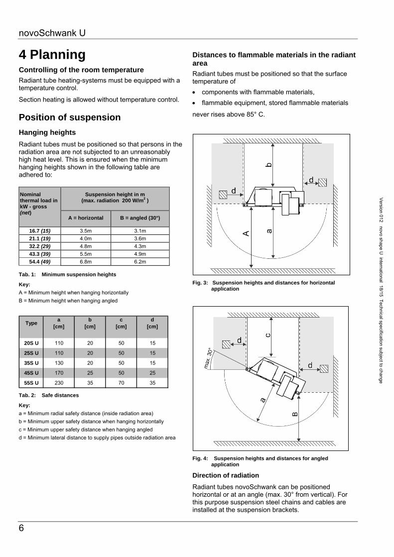
Radiant tubes must be positioned so that persons in the radiation area are not subjected to an unreasonably high heat level. This is ensured when the minimum hanging heights shown in the following table are adhered to:
Tab. 1: Minimum suspension heights
Key:
A = Minimum height when hanging horizontally
B = Minimum height when hanging angled
Typea
[cm]b
[cm]c
[cm]d
[cm]
20S U 110 20 50 15
25S U 110 20 50 15
35S U 130 20 50 15
45S U 170 25 50 25
55S U 230 35 70 35
Tab. 2: Safe distances
Key:
a = Minimum radial safety distance (inside radiation area)
b = Minimum upper safety distance when hanging horizontally
c = Minimum upper safety distance when hanging angled
d = Minimum lateral distance to supply pipes outside radiation area
Distances to flammable materials in the radiant area
Radiant tubes must be positioned so that the surface temperature of
components with flammable materials,
flammable equipment, stored flammable materials
never rises above 85° C.
Fig. 3: Suspension heights and distances for horizontal
application
Fig. 4: Suspension heights and distances for angled application
Direction of radiation
Radiant tubes novoSchwank can be positioned horizontal or at an angle (max. 30° from vertical). For this purpose suspension steel chains and cables are installed at the suspension brackets.
Nominal thermal load in kW - gross (net)
Suspension height in m (max. radiation 200 W/m2 )
A = horizontal B = angled (30°)
16.7 (15) 3.5m 3.1m
21.1 (19) 4.0m 3.6m
32.2 (29) 4.8m 4.3m
43.3 (39) 5.5m 4.9m
54.4 (49) 6.8m 6.2m

novoSchwank U
7
Ver
sion
012
no
vo s
hape
U i
nter
natio
nal
18/1
5 T
echn
ical
spe
cific
atio
n su
bjec
t to
chan
ge
Positioning The radiant tube can be mounted with
chains (links min. 4 mm)
adjustable steel cable (Schwank accessories)
If you chose chains please use bolts with lock nuts for fixing the chain to the suspension bracket.
The radiant tube has to be fixed by vertical chains etc. to the roof or to supporting devices.
Chains and steel cables have to be fixed in vertical direction or slightly diagonally outwards above the fixing points of the suspension brackets to the roof or to supporting devices. Fixing of the suspension cables or chains diagonally inwards to the centre of the heater is not permitted (see Fig. 5). Please note that the radiant tube being in operation expands several centimetres because of thermal expansion. Avoid therefore inflexible suspension.
Do not use fixing elements like open hooks etc.
Hang the heater in balance. We recommend the use of turnbuckles or adjustable steel cable grips for ease of adjustment and balance.
Fixing points for chains or steel cables on the heater are shown in Fig. 10 and 11 on pages 14 and 15.
Attention! If you do not align the burner unit correctly the device can be damaged.
Fig. 5: Chains and steel cable mounting
Fig. 6: Slope of radiant tube heater
SCHWANK GmbH will not accept liability for damages caused by incorrect mounting of the burner box. Correct mounting is the responsibility of the installer.
wrong
wrong
correct
x x
Correct = vertical or slightly diagonally outwards
Wrong = diagonally inwards
20S U / 25S U / 35S U: x=15mm 45S U: x=20mm 55S U: x=30mm
novoSchwank U
8
Version 012 novo shape U
international 18/15 Technical specification subject to change
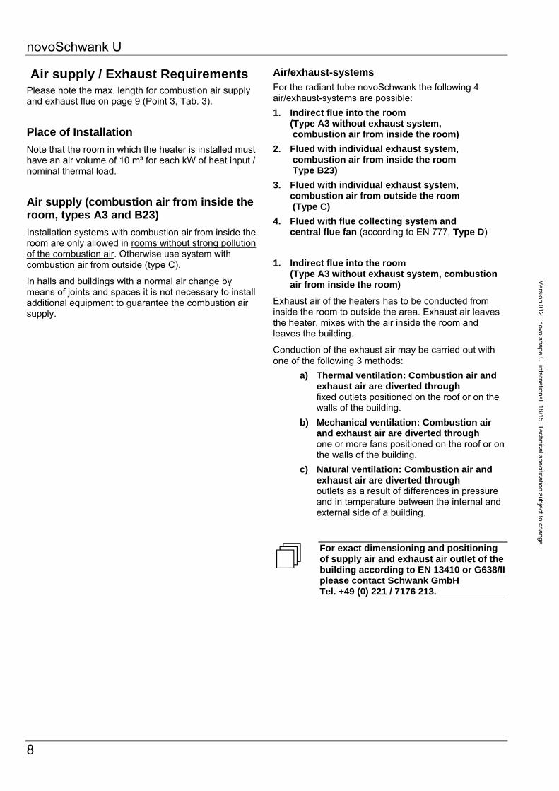
Air supply / Exhaust Requirements Please note the max. length for combustion air supply and exhaust flue on page 9 (Point 3, Tab. 3).
Place of Installation
Note that the room in which the heater is installed must have an air volume of 10 m³ for each kW of heat input / nominal thermal load.
Air supply (combustion air from inside the room, types A3 and B23)
Installation systems with combustion air from inside the room are only allowed in rooms without strong pollution of the combustion air. Otherwise use system with combustion air from outside (type C).
In halls and buildings with a normal air change by means of joints and spaces it is not necessary to install additional equipment to guarantee the combustion air supply.
Air/exhaust-systems
For the radiant tube novoSchwank the following 4 air/exhaust-systems are possible:
1. Indirect flue into the room (Type A3 without exhaust system, combustion air from inside the room)
2. Flued with individual exhaust system, combustion air from inside the room Type B23)
3. Flued with individual exhaust system, combustion air from outside the room (Type C)
4. Flued with flue collecting system and central flue fan (according to EN 777, Type D)
1. Indirect flue into the room (Type A3 without exhaust system, combustion air from inside the room)
Exhaust air of the heaters has to be conducted from inside the room to outside the area. Exhaust air leaves the heater, mixes with the air inside the room and leaves the building.
Conduction of the exhaust air may be carried out with one of the following 3 methods:
a) Thermal ventilation: Combustion air and exhaust air are diverted through fixed outlets positioned on the roof or on the walls of the building.
b) Mechanical ventilation: Combustion air and exhaust air are diverted through one or more fans positioned on the roof or on the walls of the building.
c) Natural ventilation: Combustion air and exhaust air are diverted through outlets as a result of differences in pressure and in temperature between the internal and external side of a building.
For exact dimensioning and positioning of supply air and exhaust air outlet of the building according to EN 13410 or G638/II please contact Schwank GmbH Tel. +49 (0) 221 / 7176 213.

novoSchwank U
9
Ver
sion
012
no
vo s
hape
U i
nter
natio
nal
18/1
5 T
echn
ical
spe
cific
atio
n su
bjec
t to
chan
ge
2. Exhaust flue with individual exhaust system combustion air from inside the room (Type B23)
Only use this kind of installation in rooms without pollution of the combustion air and without relevant pressure differences to the outside. Otherwise use type C.
3. Exhaust flue with individual exhaust system combustion air from outside the room (Type C)
Combustion air and exhaust air are diverted through a temperature stable, concentric tube with a roof or wall outlet.
Max. length of air and exhaust flue until the concentric tube with a roof or wall outlet is 6 m each plus two 90° elbow.
The tube which leads the combustion air to the burner box must be flexible and easy to remove for maintenance. Don’t use valves and dampers in the exhaust flue.
Tab. 3: Air/exhaust routing
4. Exhaust flue with flue collecting system and central flue fan (according to EN 777, Type D)
The whole system consists of max.10 radiant tubes. A central flue fan collects the exhaust of the several heaters in a central exhaust tube and diverts it to an outlet. If installing systems without individual flue fans of several heaters it could be necessary to integrate dampers into the connecting pipes to ensure the operation and exhaust flue of all heaters.
See technical instruction novoSchwank with flue collecting system
Fig. 7: Air/exhaust--system, version stainless steel
Max. length between heater and roof/wall
outlet
max. number of elbows
(90°)
Ø of air/exhaust flue
6 m 2 100 mm
novoSchwank U

novoSchwank U
10
Version 012 novo shape U
international 18/15 Technical specification subject to change
Indirect flue into the room with flue gas diverter, Type A3
For indirect flue into the room a flue gas diverter must be installed to prevent backflow of flue gas into the air inlet. Note that the flue gas diverter is mounted in a position so that the flue gas is diverted from the burner.
Fig. 8: Indirect flue into the room with flue gas diverter
Flue gas diverter in right
mounting position
novoSchwank U
11
Ver
sion
012
no
vo s
hape
U i
nter
natio
nal
18/1
5 T
echn
ical
spe
cific
atio
n su
bjec
t to
chan
ge
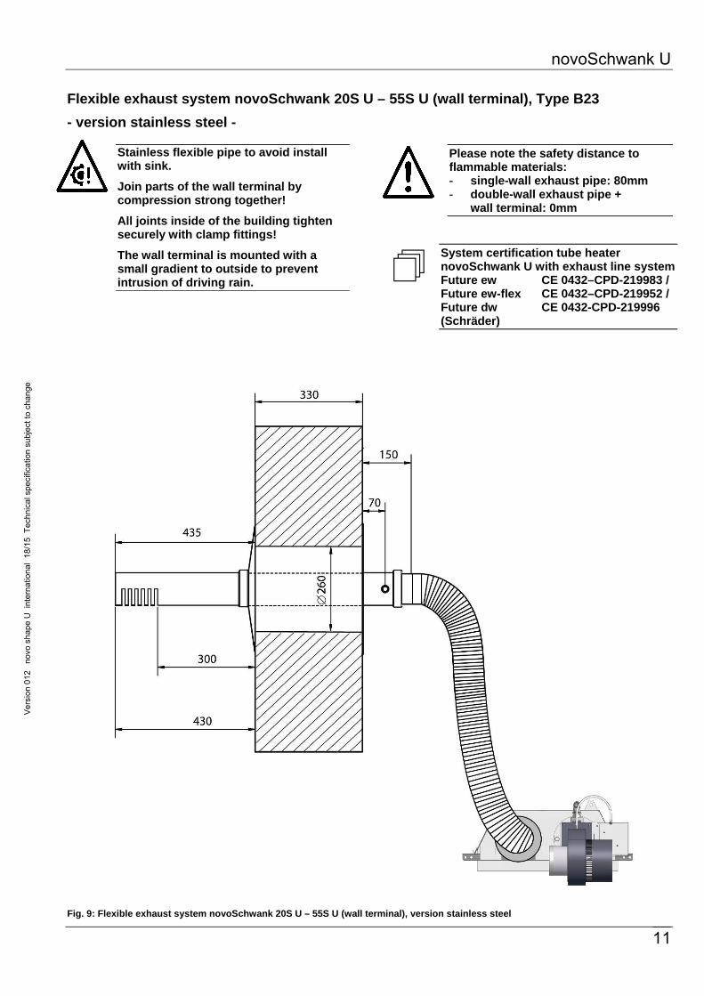
Flexible exhaust system novoSchwank 20S U – 55S U (wall terminal), Type B23
- version stainless steel -
Stainless flexible pipe to avoid install with sink.
Join parts of the wall terminal by compression strong together!
All joints inside of the building tighten securely with clamp fittings!
The wall terminal is mounted with a small gradient to outside to prevent intrusion of driving rain.
Please note the safety distance to flammable materials: - single-wall exhaust pipe: 80mm - double-wall exhaust pipe +
wall terminal: 0mm
System certification tube heater novoSchwank U with exhaust line system Future ew CE 0432–CPD-219983 / Future ew-flex CE 0432–CPD-219952 / Future dw CE 0432-CPD-219996 (Schräder)
Fig. 9: Flexible exhaust system novoSchwank 20S U – 55S U (wall terminal), version stainless steel

novoSchwank U
12
Version 012 novo shape U
international 18/15 Technical specification subject to change
Flexible exhaust system novoSchwank 20S U – 55S U (roof terminal), Type B23
- version stainless steel -
Stainless flexible pipe to avoid install with sink.
Join parts of the roof terminal by compression strong together!
All joints inside of the building tighten securely with clamp fittings!
Please note the safety distance to flammable materials: - single-wall exhaust pipe: 80mm - double-wall exhaust pipe +
roof terminal: 0mm
System certification tube heater novoSchwank U with exhaust line system Future ew CE 0432–CPD-219983 / Future ew-flex CE 0432–CPD-219952 / Future dw CE 0432-CPD-219996 (Schräder)
Fig. 10: Flexible exhaust system novoSchwank 20S U – 55S U (roof terminal), version stainless steel

novoSchwank U
13
Ver
sion
012
no
vo s
hape
U i
nter
natio
nal
18/1
5 T
echn
ical
spe
cific
atio
n su
bjec
t to
chan
ge
5 Legal Requirements We recommend that these installation guidelines should be observed with the relevant Building Standards Regulations of the corresponding country. Comply with any local bylaws and the current IEE Wiring Regulations.
Notwithstanding their limited scope, the appliance should be installed by a competent person in accordance with the relevant provisions of the Gas Safety (Installation and Use) Regulations. Due account should also be taken of any obligations arising from the Health and Safety at Work Act. Full compliance with all relevant regulations, including amendments, in force at the time of installation is a pre-requisite of our warranty.
In Germany the following rules, standards and regulations must be observed.
HeizAnlV Heizungsanlagenverordnung
HeizBetrV Heizungsbetriebsverordnung
DIN 4701 Regeln für die Berechnung des Wärmebedarfs von Gebäuden
DIN 4751 Sicherheitstechnische Ausrüstung von Heizanlagen
DIN 4756 Gasfeuerungen in Heizungsanlagen
DIN 4705 Berechnung von Schornstein- abmessungen
DIN EN 12831 Heizungsanlagen in Gebäuden - Verfahren zur Berechnung der Norm-Heizlast
DIN 18160 Hausschornsteine - Anforderungen, Planung und Ausführung
DIN V 18599 Energetische Bewertung von Gebäuden
DVGW G 600 TRGI 2008 Technische Regeln der Gasinstallation
DVGW G 638-2 Heizungsanlagen mit Dunkelstrahlern
DVGW G 660 Technische Regeln für die mechanische Abführung der Abgase von Feuerstätten
VDE 0722 Elektrische Vorschriften
VDE 0100 Bestimmungen für das Errichten von Starkstromanlagen
LBO Landesbauordnung
FeuVO Feuerungsverordnung der Länder
TAB Technische Anschluß- bedingungen der örtlichen Energieversorgungs- unternehmen

novoSchwank U
14
Version
012novo
shapeU
international18/15
Technicalspecification
subjecttochange
6 Operating The installation must be carried out by a qualified engineer following the manufacturer’s instructions.
SCHWANK GmbH will not accept liability damages caused by incorrect putting into operation of the heater. Correct putting into operation is the responsibility of the installer.
Switching on the heater Switch on the heater. The main switch is on
the control box. After a pre-purge period of about 25 sec. the ignition starts.
Switching off the heater Switch off the heater.
If the radiant tube is controlled by a thermostat the heater switches on and off automatically.
Fault If no flame is reported during the pre-purge period and the safety time (ca. 30 sec.) the heater repeats the ignition process. If there is no flame after the second ignition process the radiant tube switches off automatically and interlocks.
Investigation and repair must be carried out by authorized people. After clearance of the fault the interlock can be reset.
Interlock release (Reset)
Interrupt the electric power supply for 3 sec.
Maintenance Servicing of the heater is essential for continued efficient operation. Servicing should be carried out not less than once a year by a qualified service engineer. After any servicing the heater must be recommissioned as detailed in Chapter 12.

novoSchwank U
15
Ver
sion
012
no
vo s
hape
U i
nter
natio
nal
18/1
5 T
echn
ical
spe
cific
atio
n su
bjec
t to
chan
ge
7 Technical specification
Appliance Automatic heating device, heat transfer mainly by mean of infrared dark radiation.
Fuels Natural gas Propane
Minimum connection pressure in front of valve
Electrical connection
Single phase A.C. 230 V, N, PE - 50Hz (cycles) (approx. 80 VA)
Power supply for heater and flue fan are connected to a socket at the casing of the burner unit. To set burner unit free of voltage it is only necessary to remove the plug of the power supply.
Exhaust gas Flue pipe connection Ø 100 at connection exit of tube
Gas connection 20S U – 35S U R=1/2’’ male
45S U – 55S U R=3/4’’ male
Attention! Max. connection pressure: 60 mbar
Fig. 11: Dimensions novoSchwank 20S U / 25S U / 35S U (view from below)
Type 20S U – 55S U
Natural gas H 15mbar
Natural gas L 20mbar
Propane 40mbar
novoSchwank 35S U (all dimensions in mm)
novoSchwank 20S U / 25S U (all dimensions in mm)
Detail A/B see page 16

novoSchwank U
16
Version
012novo
shapeU
international18/15
Technicalspecification
subjecttochange
Fig. 12: Dimensions novoSchwank 45S U / 55S U (view from below)
novoSchwank 55S U (all dimensions in mm)
Detail A Cross dimensions
20S U – 55S U A=80mm
Detail B Cross dimensions reflector valid for all types
novoSchwank 45S U (all dimensions in mm)

novoSchwank U
17
Ver
sion
012
no
vo s
hape
U i
nter
natio
nal
18/1
5 T
echn
ical
spe
cific
atio
n su
bjec
t to
chan
ge
Technical data
Gas
20S U 25S U 35S U 45S U 55S UNatural gas H Gas input - gross [kW] 16,7 21,1 32,2 43,3 54,4
Gas input - net [kW] 15.0 19.0 29.0 39.0 49.0
G 20 1) Gas consumption [m3/h] 1.50 1.91 2.91 3.91 4.91
Natural gas L Gas input - gross [kW] 16,7 21,1 32,2 43,3 54,4
Gas input - net [kW] 15.0 19.0 29.0 39.0 49.0
G 25 2) Gas consumption [m3/h] 1.75 2.22 3.38 4.55 5.72
Propane Gas input - gross [kW] 16,4 20,7 31,6 42,5 53,4
Gas input - net [kW] 15.0 19.0 29.0 39.0 49.0
G 31 3) Gas consumption [kg/h] 1.17 1.48 2.25 3.03 3.81
Weight [kg] 50 50 70 85 120
of air/exhaust flue [mm]Electrical consumption [W] 91Electrical protectionGas connection (male thread)Electrical supplyIgnition / Control
CE-Identification
by automatic controller systemCE - 0085 BO 0037
R½“ R3/4“
novoSchwank
Ø 100
IP 20104
230 V/ 50 Hz ~ Spark ignition and ionisation control
1) Hi,n = 9.97 kWh/m3 / 2) Hi,n = 8.57 kWh/m3 / 3) Hi,n = 12.87 kWh//kg
Tab. 4: Technical data novoSchwank U
1) Hi,n = 9.97 kWh/m3 / 2) Hi,n = 8.57 kWh/m3 / 3) Hi,n = 12.87 kWh//kg
Tab. 5: Function parts burner unit novoSchwank U
Gas
20S U 25S U 35S U 45S U 55S UNatural gas H Burner nozzle [mm] Ø 3.50 Ø 3.85 Ø 5.00 Ø 5.85 Ø 6.90G 20 1) Fan air restrictor plate N 20S N 25S N 35S N 45S N 55S
Air baffle plate N 20S N 25S N 35S + spin / spin N55SBurner baffle plate Ø 50 Ø 65 Ø 65 / /Nozzle pressure [mbar] 10 10 10 10 10Start step pressure [mbar] 5 5 5 4 4
Natural gas L Burner nozzle [mm] Ø 3.50 Ø 3.85 Ø 5.00 Ø 5.85 Ø 6.90G 25 2) Fan air restrictor plate N 20S N 25S N 35S N 45S N 55S
Air baffle plate N 20S N 25S N 35S + spin / spin N55SBurner baffle plate Ø 50 Ø 65 Ø 65 / /Nozzle pressure [mbar] 15,2 15,2 15,2 15,2 15,2Start step pressure [mbar] 7 7 7 6 6
Propane Burner nozzle [mm] Ø 1.95 Ø 2.15 Ø 2.80 Ø 3.25 Ø 3.65G 31 3) Fan air restrictor plate N 20S N 25S N 35S N 45S N 55S
Air baffle plate N 20S N 25S N 35S + spin / spin N55SBurner baffle plate Ø 50 Ø 65 Ø 65 / /Nozzle pressure [mbar] 37 37 37 37 37Start step pressure [mbar] 22 22 22 22 22
novoSchwank
novoSchwank U
18
Version
012novo
shapeU
international18/15
Technicalspecification
subjecttochange
8 Operating description
Start-up
If heat demand exists the fan will start up. A differential pressure builds up in the burner casing, which is reported to the ignition unit via the differential pressure switch.
After a pre-purge period of about 25 seconds the automatic ignition starts (max. ignition time 5 sec.). The twin solenoid valve with pressure regulator opens in 2 steps the gas supply to the burner. The burner flame is controlled by an ionisation electrode. The ignition is switched off, if the ionisation electrode reports a flame to the ignition and control unit during the safety time.
If the ignition process fails the ignition unit repeats the start-up for one time.
Operation
A superbly long laminar flame is created in the first tube by the special burner construction. The hot flue heats the tube surface while being fed through the tubes by the fan. The hot tubes emit long-waved infrared radiation which is directed to the room by the reflector construction.
The radiant tube novoSchwank works with a closed combustion system. The combustion air is taken from the room or from outside. The flue is evacuated indirectly into the room or directly by exhaust pipe or by a special air/exhaust pipe system.
Fault
If no flame is reported during the pre-purge period (including 1 repetition of ignition process) the ignition unit will switch off the radiant tube and will interlock.
Investigation and repair must be carried out by authorized people. After clearance of the fault the interlock can be reset.
The interlock release is carried out by interruption of the electric power supply for 3 sec. A new start-up begins. If no flame signal is reported to the firing device during operation the solenoid valve shuts and stops the gas supply immediately. A new start-up process is repeated.
Troubleshooting: page 30
Monitoring of the combustion air supply
The combustion air supply is permanently controlled by the differential pressure switch during the operation. If the differential pressure switch is not in rest position during the start-up the operation won’t start. If the operating contact isn’t closed during the pre-purge the system will set in interference release. If combustion air supply failed during operation (lack of air) the differential pressure switch will close the gas combination valve and stop the gas supply. A new start-up process is repeated.
novoSchwank U
19
Ver
sion
012
no
vo s
hape
U i
nter
natio
nal
18/1
5 T
echn
ical
spe
cific
atio
n su
bjec
t to
chan
ge
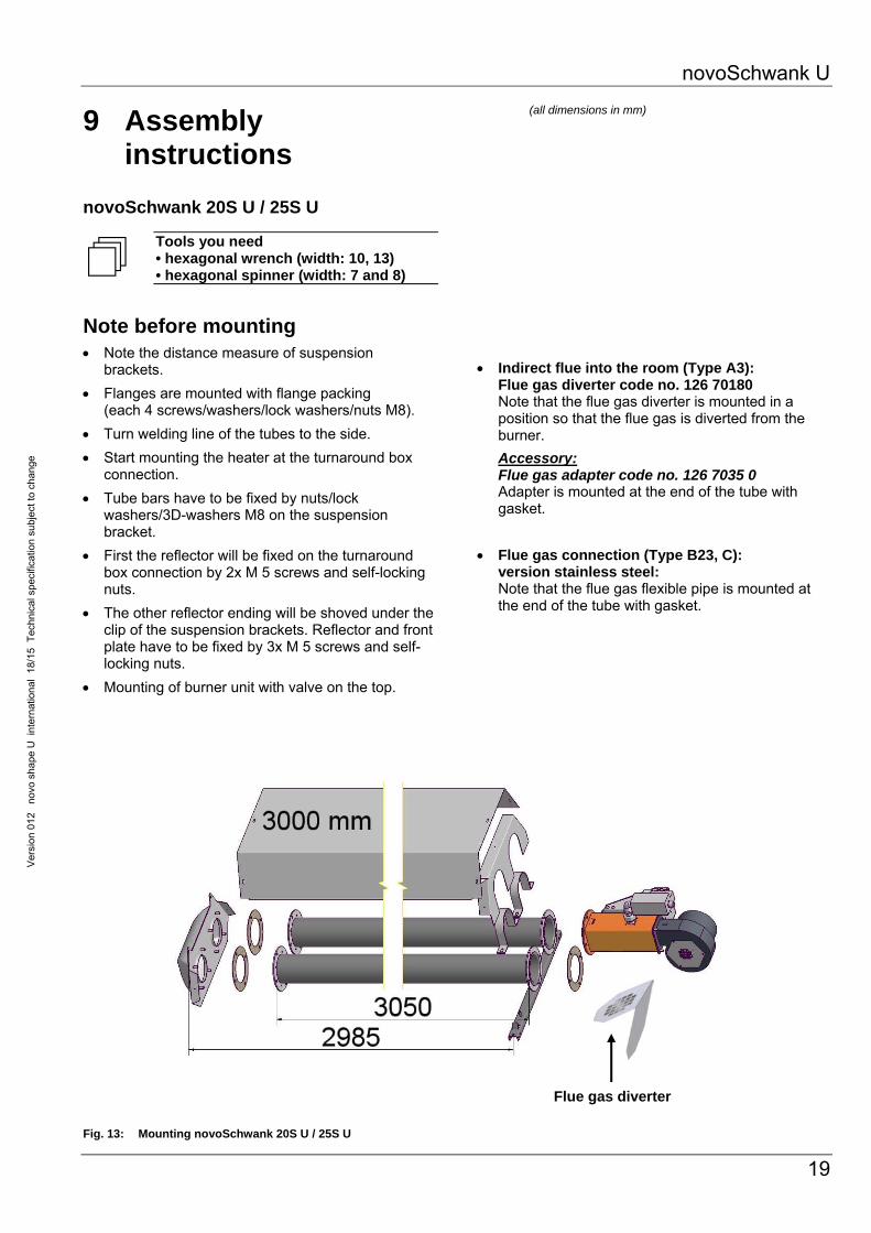
9 Assembly instructions
novoSchwank 20S U / 25S U
Tools you need • hexagonal wrench (width: 10, 13) • hexagonal spinner (width: 7 and 8)
Note before mounting Note the distance measure of suspension
brackets.
Flanges are mounted with flange packing (each 4 screws/washers/lock washers/nuts M8).
Turn welding line of the tubes to the side.
Start mounting the heater at the turnaround box connection.
Tube bars have to be fixed by nuts/lock washers/3D-washers M8 on the suspension bracket.
First the reflector will be fixed on the turnaround box connection by 2x M 5 screws and self-locking nuts.
The other reflector ending will be shoved under the clip of the suspension brackets. Reflector and front plate have to be fixed by 3x M 5 screws and self-locking nuts.
Mounting of burner unit with valve on the top. Fig. 13: Mounting novoSchwank 20S U / 25S U
(all dimensions in mm)
Indirect flue into the room (Type A3): Flue gas diverter code no. 126 70180 Note that the flue gas diverter is mounted in a position so that the flue gas is diverted from the burner.
Accessory: Flue gas adapter code no. 126 7035 0
Adapter is mounted at the end of the tube with gasket.
Flue gas connection (Type B23, C): version stainless steel: Note that the flue gas flexible pipe is mounted at the end of the tube with gasket.
Flue gas diverter
novoSchwank U
20
Version
012novo
shapeU
international18/15
Technicalspecification
subjecttochange
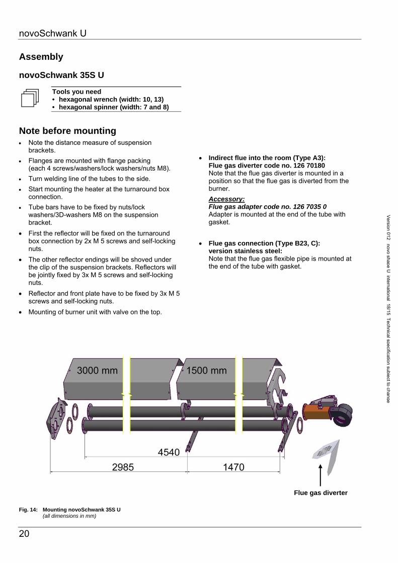
Assembly
novoSchwank 35S U
Tools you need • hexagonal wrench (width: 10, 13) • hexagonal spinner (width: 7 and 8)
Note before mounting Note the distance measure of suspension
brackets.
Flanges are mounted with flange packing (each 4 screws/washers/lock washers/nuts M8).
Turn welding line of the tubes to the side.
Start mounting the heater at the turnaround box connection.
Tube bars have to be fixed by nuts/lock washers/3D-washers M8 on the suspension bracket.
First the reflector will be fixed on the turnaround box connection by 2x M 5 screws and self-locking nuts.
The other reflector endings will be shoved under the clip of the suspension brackets. Reflectors will be jointly fixed by 3x M 5 screws and self-locking nuts.
Reflector and front plate have to be fixed by 3x M 5 screws and self-locking nuts.
Mounting of burner unit with valve on the top. Fig. 14: Mounting novoSchwank 35S U (all dimensions in mm)
Indirect flue into the room (Type A3): Flue gas diverter code no. 126 70180 Note that the flue gas diverter is mounted in a position so that the flue gas is diverted from the burner.
Accessory: Flue gas adapter code no. 126 7035 0
Adapter is mounted at the end of the tube with gasket.
Flue gas connection (Type B23, C): version stainless steel: Note that the flue gas flexible pipe is mounted at the end of the tube with gasket.
Flue gas diverter

novoSchwank U
21
Ver
sion
012
no
vo s
hape
U i
nter
natio
nal
18/1
5 T
echn
ical
spe
cific
atio
n su
bjec
t to
chan
ge
Assembly
novoSchwank 45S U
Tools you need • hexagonal wrench (width: 10, 13) • hexagonal spinner (width: 7 and 8) hand rivet tool, drill machine, drill 4.9mm
Note before mounting Note the distance measure of suspension
brackets.
Flanges are mounted with flange packing (each 4 screws/washers/lock washers/nuts M8).
Turn welding line of the tubes to the side.
Start mounting the heater at the turnaround box connection.
Tube bars have to be fixed by nuts/lock washers/3D-washers M8 on the suspension bracket.
Supporting sleeve for first flange connection: Insert half of the supporting sleeve into first heater tube (slot on top). Drill Ø 4.9mm hole through the tube and sleeve and fix it by rivet. Mount the second tube and fix the sleeve by the rivet as well. Fix the rivets always in the opposite position lateral to the tube. Use only stainless rivets.
First the reflector will be fixed on the turnaround box connection by 2x M 5 screws and self-locking nuts.
The other reflector endings will be shoved under the clip of the suspension brackets. Reflectors will be jointly fixed by 3x M 5 screws and self-locking nuts.
Reflector and front plate have to be fixed by 3x M 5 screws and self-locking nuts.
Mounting of burner unit with valve on the top. Fig. 15: Mounting novoSchwank 45S U (all dimensions in mm)
Indirect flue into the room (Type A3): Flue gas diverter code no. 126 70180 Note that the flue gas diverter is mounted in a position so that the flue gas is diverted from the burner.
Accessory: Flue gas adapter code no. 126 7035 0
Adapter is mounted at the end of the tube with gasket.
Flue gas connection (Type B23, C): version stainless steel: Note that the flue gas flexible pipe is mounted at the end of the tube with gasket.
Supporting sleeve
4 rivets (stainless) Ø 4.8 mm hole size Ø 4.9mm
Flue gas diverter

novoSchwank U
22
Version
012novo
shapeU
international18/15
Technicalspecification
subjecttochange
Assembly
novoSchwank 55S U
Tools you need • hexagonal wrench (width: 10, 13) • hexagonal spinner (width: 7 and 8)
Note before mounting Note the distance measure of suspension
brackets.
Flanges are mounted with flange packing (each 4 screws/washers/lock washers/nuts M8).
Turn welding line of the tubes to the side.
Start mounting the heater at the turnaround box connection.
Tube bars have to be fixed by nuts/lock washers/3D-washers M8 on the suspension bracket.
First the reflector will be fixed on the turnaround box connection by 2x M 5 screws and self-locking nuts.
The other reflector endings will be shoved under the clip of the suspension brackets. Reflectors will be jointly fixed by 3x M 5 screws and self-locking nuts.
Reflector and front plate have to be fixed by 3x M 5 screws and self-locking nuts.
Mounting of burner unit with valve on the top.
Fig. 16: Mounting novoSchwank 55S U (all dimensions in mm)
Indirect flue into the room (Type A3): Flue gas diverter code no. 126 70180 Note that the flue gas diverter is mounted in a position so that the flue gas is diverted from the burner.
Accessory: Flue gas adapter code no. 126 7035 0
Adapter is mounted at the end of the tube with gasket.
Flue gas connection (Type B23, C): version stainless steel: Note that the flue gas flexible pipe is mounted at the end of the tube with gasket
Flue gas diverter

novoSchwank U
23
Ver
sion
012
no
vo s
hape
U i
nter
natio
nal
18/1
5 T
echn
ical
spe
cific
atio
n su
bjec
t to
chan
ge
10 Installation instructions
Danger of fire and explosion! Unprofessional handling with gas pipes, gas connections and supplied devices can produce gas leaks. It is highly dangerous if gas is ignited! Working with gas pipes and supplied appliances is only allowed by approved installers.
Mount the flexible connection so that it can compensate the longitudinal expansion of the tube. Only use flexible connections for the radiant tube regarding: • gas • electricity and • air (if necessary)
Fig. 17: Longitudinal expansion
Gas-pipe-system and mounting of heaters Assembling of gas pipes to the appliance, supply and the mounting of the appliance is only allowed by a competent person who is registered, holding a current certificate of competence and in accordance with the relevant provisions of the gas safety (installation and use) regulations.
Additional installation notices of national or local institutions must be observed. The pipe must be dimensioned in that way that the minimum connection pressure in front of the gas combination valve of the individual devices are available at the nominal thermal load of the entire system, according to table 6.
Please consider the pressure drop of the upstream mounted gas connection and gas filter. For the detailed pressure drop value of the Schwank gas-pipe-systems see table 7.
Minimum connection pressures in front of valve
Type nozzle start step
pressure pressure
[mbar] [mbar] [mbar]
Natural gas H*
20S U - 55S U 15 10 4 - 5
Natural gas L*
20S U - 55S U 20 15.2 6 - 7
Propane 20S U - 55S U 40 37 22
* Natural gas H: Hi,n: 9.97 kWh/m3 Natural gas L: Hi,n: 8.57 kWh/m3
novoSchwank shape U
min.
connection
pressure
Tab. 6: min. connection pressures in front of gas
combination valve
Pressure drop Schwank flexible gas-pipe-systems
novoSchwank shape U
Type Gas pipe system
Pressure drop [mbar]
Natural gas H
20S U – 35S U 1/2" / L=800mm 2
45S U – 55S U 3/4" / L=800mm 2
Natural gas L
20S U – 35S U 1/2" / L=800mm 2
45S U – 55S U 3/4" / L=800mm 2.5
Propane 20S U – 35S U 1/2" / L=800mm 1
45S U – 55S U 3/4" / L=800mm 1
Tab. 7: Pressure drop Schwank flexible gas-pipe-systems
The max. connection pressure is 60mbar!
In case of contaminated gas pipes and generally at gas pipes of welded black steel have to be mounted gas filter-groups directly in front of the heater (see page 37).
a
b

novoSchwank U
24
Version
012novo
shapeU
international18/15
Technicalspecification
subjecttochange
Note the following points while installing the gas-pipe-system:
Use only gas lines as per national standards.
Never hang heaters on the gas pipes.
Mount a manual gas cock upstream of every radiant tube.
Close all gas cocks before carrying out the leak test and disconnect the connection between the gas cock and the burner to avoid damages to the gas regulator and gas combination valve.
Clean gas pipes before the installation of the heater. Reconnection after pressure control and expansion.
Please observe the national standards.
Connect the heater with an approve flexible hose
Use the following hose length:
Mount only a flexible hose with 90° bend or with 2 x 90° elbow with 180° bend according to Fig. 18, 19 and 20.
Keep the specified installation dimensions.
Wrong mounting of flexible hoses shown in
Fig. 21 (sketches to )
Fig. 18: Stand connection 90° bend
Fig. 19: lateral connection 90° bend
Fig. 20: Alternative flexible hose 180° -bend with 2 x 90° elbow
Fig. 21: Wrong mounting of flexible hoses
20S U – 35S U R ½“ length 800mm
45S U – 55S U R ¾“ length 800mm
430 mm (+/- 10%)
430
mm
(+
/- 1
0%
)
430
mm
(+
/- 1
0%)
430 mm(+/- 10%)
a = 320 mm +/- 10% h = 150 mm h: allowable height displacement for mounting

novoSchwank U
25
Ver
sion
012
no
vo s
hape
U i
nter
natio
nal
18/1
5 T
echn
ical
spe
cific
atio
n su
bjec
t to
chan
ge
Flue installation The flue system is available as accessories to the radiant tube novoSchwank. The flue system is connected at the end of the radiant tube. Note to information in Chapter 4 „Planning“.
Electrical installation (wiring diagram)
Danger of electric shock! Electric shocks are dangerous! Working at the electrical equipment of the appliance is only allowed by competent persons observing the current IEE regulations.
Isolate the electrical supply while working at the electrical equipment of the appliance.
The gas supply and electrical cable must be situated on the outside of the area of the heater radiation or it’s combustion products. Only use heat-resistant cables near the tubes.
Electrical connection Route the connection cable (power supply) to the
four-pin plug and connect cables.
Put the four-pin plug into the socket at the burner casing.
Connect the plug of the fan into the corresponding socket at the burner casing.
Pay attention of correct polarity! If polarity is incorrect the firing device will not register ionisation signal!
You find the four-pin socket for the electrical supply in the burner unit.

novoSchwank U
26
Version
012novo
shapeU
international18/15
Technicalspecification
subjecttochange
Fig. 22: Connecting diagram novoSchwank U
Fig. 23: Wiring diagram burner unit novoSchwank U
Burner unit
Control Box Thermocontrol Plus M /unoSchwank
L N PE
L N PE
Gas valve VK 4105C
Electrical supply 1~230Volt, 50Hz, N, PE
1
2
PE
single-stage operation
3
P

novoSchwank U
27
Ver
sion
012
no
vo s
hape
U i
nter
natio
nal
18/1
5 T
echn
ical
spe
cific
atio
n su
bjec
t to
chan
ge
11 Commissioning instructions
Before putting into operation
A qualified and permitted service engineer must carry out this operation. The correct operation and fixing of the heater is prerequisite for our liability. Checking gas lines and flue system is not included in the fixing.
Check function of the following equipment:
Exhaust flue
Combustion air supply
Control unit
Safety equipment
Safety of electrical circuit
Pay attention after putting into operation! Vaporization of remaining grease of metal units may cause greasy mist. This kind of mist disperses after approx. 30 minutes. During this time the room has to be ventilated.
Adjusting nominal thermal load
Attention! The pressure control unit is pre-adjusted on natural gas. Do not put the appliance into operation without controlling.
Adjusting the nozzle pressure
1. Open first the gas cock which is at the end of the flexible gas hose (Fig. 24, page 28).
2. Open the test nipple connection pressure. Connect the pressure measuring instrument to the test nipple and determine the connection pressure. Close the test nipple after the measurement!
3. Open the test nipple nozzle pressure. Connect the pressure measuring instrument to the test nipple and determine the nozzle pressure.
4. Put the radiant tube into operation.
5. Turn the adjusting screw on the pressure regulator slowly in the “+” or “-” -direction while continuously watching the pressure measuring instrument. Stop turning as soon as the required nozzle pressure is reached. The required nozzle pressure for natural gas H (Wo =14.85 kWh/m3) and natural gas L (Wo =12.15 kWh/m3) is shown in table 5 page 17. For natural gas with other Wo-Index (information from local gas company) you have to determine the required nozzle pressure from the diagram on page 28.
6. Remove the protection cap A (see Fig. 25, page 28).
7. Put the radiant tube into operation.
8. Turn the adjusting screw B (see Fig. 25, page 28) on the pressure regulator slowly in the “+” or “-” -direction while continuously watching the pressure measuring instrument. Stop turning as soon as the required nozzle pressure is reached.
9. Put the protection cap A on the valve after the adjusting.
10. Close the test nipple after the measurement and check if the test nipple is gas-tight.

novoSchwank U
28
Version
012novo
shapeU
international18/15
Technicalspecification
subjecttochange
Checking adjustment 1. Turn the adjustment screw slightly to “-“
-direction. Orifice pressure must drop immediately. If this does not happen, you must readjust the orifice pressure until the point is reached at which a decrease or increase in the nozzle pressure is noticeable on the measuring instrument when the adjustment screw is turned slightly to “+” or “-“ direction.
2. Close test nipple after the measurement!
3. Remove the measuring instrument and check if the test nipple is gastight.
Fig. 24: Gas cock with integrated TSD
Fig. 25: Adjusting screw nozzle pressure gas combination valve
A
B
novoSchwank U
29
Ver
sion
012
no
vo s
hape
U i
nter
natio
nal
18/1
5 T
echn
ical
spe
cific
atio
n su
bjec
t to
chan
ge
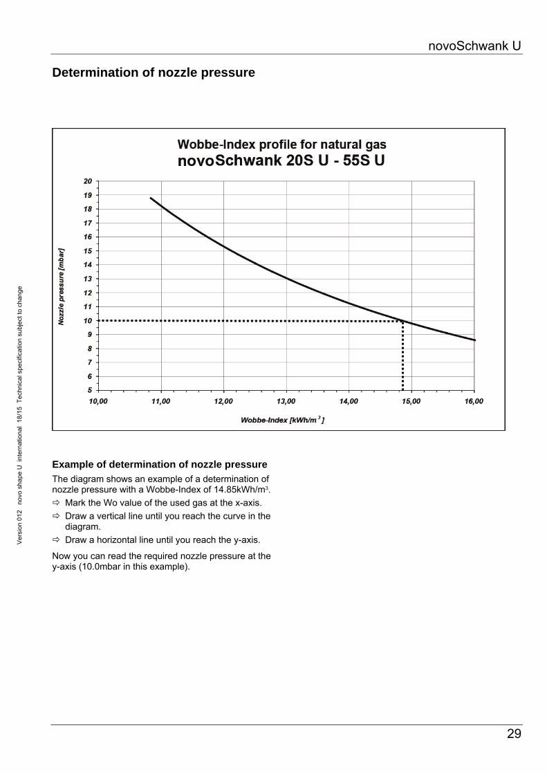
Determination of nozzle pressure
Example of determination of nozzle pressure
The diagram shows an example of a determination of nozzle pressure with a Wobbe-Index of 14.85kWh/m3.
Mark the Wo value of the used gas at the x-axis.
Draw a vertical line until you reach the curve in the diagram.
Draw a horizontal line until you reach the y-axis.
Now you can read the required nozzle pressure at the y-axis (10.0mbar in this example).

novoSchwank U
30
Version
010novo
shapeU
international25/13
Technicalspecification
subjecttochange
12 Service guide / Trouble shooting
Maintenance and annual check
A regular maintenance is assumption for a faultless operation of the appliance.
According to the national Standard Regulations heating-systems with radiant tubes must be checked minimum once a year.
Maintenance and trouble shooting is only allowed by persons who are competent and instructed in radiant tubes.
Before the beginning on works on the heater the gas cock is to be closed.
Maintenance must include the following checks:
Check the surface of radiant tubes
Check the pollution and sooting of tubes clean (if necessary)
Check tightness of the tube system including connection to the burner unit
Check the air/flue-system clean (if necessary)
Check the gas connection Leakage-test
Check the connection pressure, nozzle pressure and start step
Check gas filter in case of reduced line pressure, in case of pollution change filter set
Check the safety functions of the ignition- and ionisation-controls
Check the valve functions
Check the function of the pressure switch
Check the electrical connections
Check the slope of the tubes (3 mm/m in direction of the turnaround box connection)
Check the flexible gas hose and electrical connection to the burner unit
Check the room temperature control
Check the distances to any flammable materials
Check the air/flue ventilation of the room
Remove condensation water in the tube
Check correct connection of the reflectors
Check if the fan impeller runs correctly and is free of any damages
Check the tight fit of the fan venturi
Check connection and tightness of the fan to the burner unit
Works which are necessary must be done immediately. Defect parts must be changed directly.
Pressure switches, pressure regulators, valves and safety- and ignition devices can only be maintained by the manufacturer or authorized people.
Trouble shooting
In case of doubt, please contact SCHWANK GmbH,
phone +49 (0) 221 / 7176 213.
fault reason
burner doesn't start• no gas (check pre- and nozzle
pressure)
• fault in electrical supply
• thermostat "OFF"
• connection of ignition- and ionisation electrode is wrong
• differential pressure switch is defect or out of order (contact must be open)
• flame signal is pretended by electrical defect of control
• underpressure is not sufficient
control goes in fault position during the safety time
• no flame (no ignition, valve doesn't open, no gas)
• none or poor flame signal (flame doesn't stick, bad insulation of the flame detector, no contact between burner and earth connection)
• wrong polarity
control goes in • flame is off
fault position during the operation
• contact of differential pressure switch doesn't open
• flame signal is to poor
control goes in fault position during the pressure time

novoSchwank U
31
Ver
sion
012
no
vo s
hape
U i
nter
natio
nal
18/1
5 T
echn
ical
spe
cific
atio
n su
bjec
t to
chan
ge
13 Change of gas family
Fig. 26: Change of gas family
Burner baffle (only 20S U / 25S U / 35S U)
Burner cup
Burner nozzle
Air baffle plate (only 20S U / 25S U / 35S U / 55S U)
Fan air restrictor
Instruction to change the gas family
1. Change the burner nozzle
2. Change the burner ceramic tile or the whole burner cup only for 55S U
3. Adjust the new nozzle pressure (see tab. 5, page 17)
4. Adjust the new start step pressure (see tab. 5, page 17)
5. Stick on the new rating label

novoSchwank U
32
Version
012novo
shapeU
international18/15
Technicalspecification
subjecttochange
14 Accessories
Ball guards Ball protection grids acc.18032-3 for using heaters in sport halls (grid 40x40mm).
Delivery scope
Mounting set complete for each type of heater existing of:
novoSchwank shape U 20S U 25S U 35S U 45S U 55S U
Ball protection grid L=1843mm 2x 2x 2x 2x
Ball protection grid L=2203mm 1x
Ball protection grid L=2963mm 1x 1x 2x
Protection grid burner top 1x 1x 1x 1x 1x
Front protection cover burner 1x 1x 1x 1x 1x
Protection grid burner end side 1x 1x 1x 1x 1x
End bracket with stud bolts M8 1x 1x 1x 1x 1x
Holding bracket 1x 1x 1x 1x 1x
Angled bracket with stud bolt M8 4x 4x 6x 6x 8x
Clamp 6x 6x 8x 8x 10x
Set fixing material 1x 1x 1x 1x 1x Tab. 8: Overview delivery scope ball guards
Assembling (Description for heater novoSchwank 45S U, other types similar) 1. Mounting heater as usually acc. manual
(see chapter 9, page 19 - 22).
2. Fix end bracket at inner side of turnaround box, open and close again 4 nuts M8 (Fig. 28, page 34)
3. Fix two angled brackets at each tube hanger (screws M8 x 60, nuts) (Fig. 29, page 34) Screw on angled brackets at the inner holes of suspension bracket
4. Holding bracket put loose on the first reflector (view from burner unit) and screw together with two angled brackets (screws M8 x 60, nuts), holding bracket remain axially movable ) (Fig. 30, page 34).
5. Assembling segments ball protection grids starts on the turnaround box. Put first segment ball protection grid L=2963 mm from below on end bracket and angled brackets of the next suspension bracket – Put clamps on stud bolts M8 and mount with self-locking nuts Mount clamp loose on one stud bolt of angled bracket for further assembling next protection grid (Fig. 31, page 34).
6. Put next segment ball protection grid L= 1843mm from below on angled brackets and mount clamp with self-locking nuts M8, clamp and angled bracket connect two segments ball protection grid to each other. Mount clamp loose on one stud bolt of angled bracket for further assembling next protection grid.
7. Put next segment ball protection grid L= 1843mm from below on angled brackets and mount clamps with self-locking nuts M8 Last segment ball protection grid L= 1843mm protects the burner unit at the bottom.
8. After finish assembling of all ball protection grids fix holding bracket with 3x self-tapping screws on the reflector.
9. Push on protection grid burner top from behind over ball protection grid and burner up to the suspension bracket. Note that the lower short bending is on the left side in view from behind. Fix burner protection grid burner top with supplied cable straps or similar at bottom protection grid

novoSchwank U
33
Ver
sion
012
no
vo s
hape
U i
nter
natio
nal
18/1
5 T
echn
ical
spe
cific
atio
n su
bjec
t to
chan
ge
10. Protection grid burner top has to be cut holes depends on installation on-site for flue system and may be gas line. Connect flue system pipes and gas line. NOTE: Select the cut outs large enough to compensate the thermal length expansion of the heater!
11. Insert front protection cover burner between front cover plate reflector and burner unit and fix it with supplied cable straps or similar on protection grid burner top (Fig. 32, page 34).
12. Protection grid burner end side has to be cut hole depends on installation on-site for gas line. Fix with supplied cable straps or similar on protection grid burner top.
Please note the required number and length of segments ball protection grids for each type of heater. Compare this to the tabular and graphical overview
Fig. 27: Overview of ball guards

novoSchwank U
34
Version
012novo
shapeU
international18/15
Technicalspecification
subjecttochange
Fig. 28: Fixed end bracket on turnaround box
Fig. 29: Fixed angled bracket on suspension bracket
Fig. 30: Holding bracket novoSchwank U
Fig. 31: Loose mounted clamp
Fig. 32: Fixing front protection cover burner on protection
grid burner top

novoSchwank U
35
Ver
sion
012
no
vo s
hape
U i
nter
natio
nal
18/1
5 T
echn
ical
spe
cific
atio
n su
bjec
t to
chan
ge
Reflector elongation Vertical elongation of reflectors b=415mm for thermal protection. The numbers reflector elongation (single sheets) is depend on required protection (one side both side, protection length) and the power of the radiant heater.
Delivery scope
Reflector elongation consists of:
numbers of sheet reflector elongation
mounting material
Assembling 1. Assembling and mounting tubes with reflectors
complete acc. manual (see chapter 9, page 19-22).
2. Fix screws with distance sleeve and mounting angles A at hangers as required.
3. Mount end bracket B at turnaround box.
4. Put reflector elongation sheet B on mounting angle A. Screw both parts together with the added clip C and screw/nut M8 and lock a nut to ensure the reflector elongation sheets.
5. Fix reflector elongation sheets to another with screw/nut M8.
At heaters with axial reflector elongation the last suspension bracket on the burner side must be mounted at the junction point reflector/reflector end plate.
Fig. 33, 34: Assembling order reflector elongation
Set angled mounting tubes
Bracket to ensure form and position of reflectors when the heater is mounted angled (>15°). Bracket to mount at each junction point reflector/reflector, not at reflector end caps.
Delivery scope
Mounting set consist of:
numbers of brackets
mounting material
Assembling 1. Assembling and mounting of tubes complete
(without reflectors) acc. manual (see chapter 9, page 19-22).
2. Lay first reflector on turnaround box and first hanger, fix it at turnaround box with two screws.
3. Fix angled bracket D with screws and nuts M8 at first hanger, bracket under reflector.
4. Put on next reflector, reflectors are fixed to another by 3 screws/nuts M5, middle screw through angled bracket.
5. Further assembling as usually acc. to manual.
Fig. 35, 36: Assembling order set angled mounting
B C
D
C
A
D
novoSchwank U
36
Version
012novo
shapeU
international18/15
Technicalspecification
subjecttochange
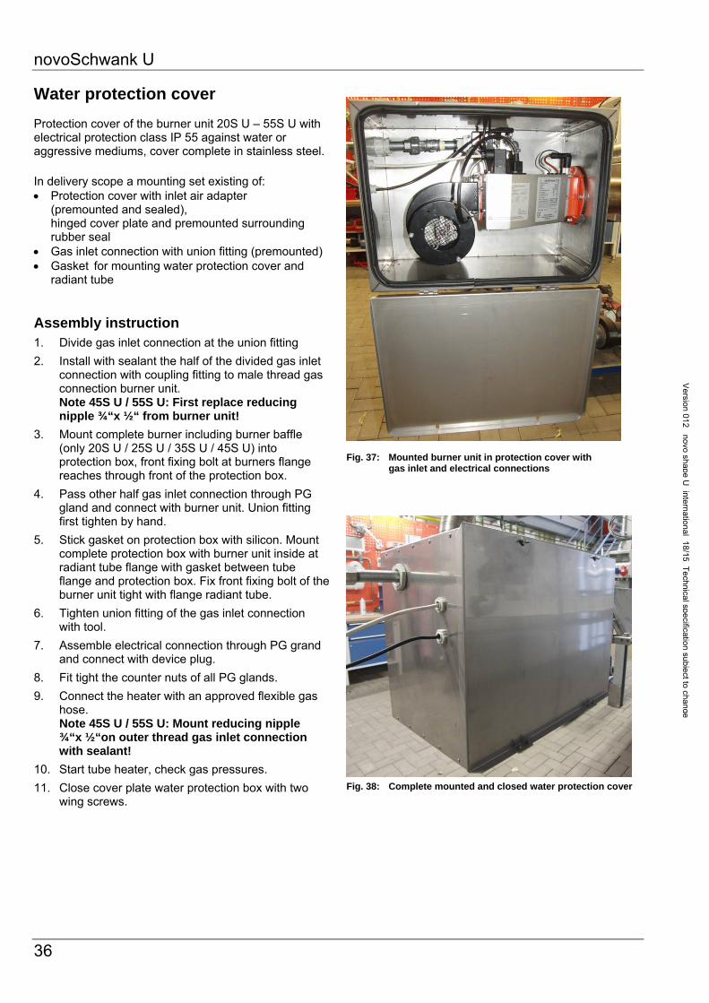
Water protection cover Protection cover of the burner unit 20S U – 55S U with electrical protection class IP 55 against water or aggressive mediums, cover complete in stainless steel. In delivery scope a mounting set existing of: Protection cover with inlet air adapter
(premounted and sealed), hinged cover plate and premounted surrounding rubber seal
Gas inlet connection with union fitting (premounted) Gasket for mounting water protection cover and
radiant tube
Assembly instruction 1. Divide gas inlet connection at the union fitting
2. Install with sealant the half of the divided gas inlet connection with coupling fitting to male thread gas connection burner unit. Note 45S U / 55S U: First replace reducing nipple ¾“x ½“ from burner unit!
3. Mount complete burner including burner baffle (only 20S U / 25S U / 35S U / 45S U) into protection box, front fixing bolt at burners flange reaches through front of the protection box.
4. Pass other half gas inlet connection through PG gland and connect with burner unit. Union fitting first tighten by hand.
5. Stick gasket on protection box with silicon. Mount complete protection box with burner unit inside at radiant tube flange with gasket between tube flange and protection box. Fix front fixing bolt of the burner unit tight with flange radiant tube.
6. Tighten union fitting of the gas inlet connection with tool.
7. Assemble electrical connection through PG grand and connect with device plug.
8. Fit tight the counter nuts of all PG glands.
9. Connect the heater with an approved flexible gas hose. Note 45S U / 55S U: Mount reducing nipple ¾“x ½“on outer thread gas inlet connection with sealant!
10. Start tube heater, check gas pressures.
11. Close cover plate water protection box with two wing screws.
Fig. 37: Mounted burner unit in protection cover with
gas inlet and electrical connections Fig. 38: Complete mounted and closed water protection cover

novoSchwank U
37
Ver
sion
012
no
vo s
hape
U i
nter
natio
nal
18/1
5 T
echn
ical
spe
cific
atio
n su
bjec
t to
chan
ge
Gas filter - groups To avoid technical problems with the gas combination valves which are caused by pollution of dust or rust coming out of the gas pipe have to be mounted a gas filter-group ¾“ (gas filter + premounted double nipple) for each tube heater 55S U.
For tube heaters 20S U – 35S U a similar gasfilter-group ½“ has to be ordered in case the gas pipe is made of black steel (welded).
Assembly instruction
Direct installation between flexible gas pipe and valve burner unit, with a slight radial slope for better cleaning the filter bottom! In case of strong polluted filter pad use the corresponding spare part set for gas filter.
Pay attention to the flow direction of the filter!
Fig. 39: Mounted gas filter-group at tube heater
gas filter-group Rp ½“ for 20S U – 35S U
code no: 192 0756 0
gas filter-group Rp 3/4“ for 45S U – 55S U
code no: 192 0757 9
novoSchwank U
38
Version
012novo
shapeU
international18/15
Technicalspecification
subjecttochange
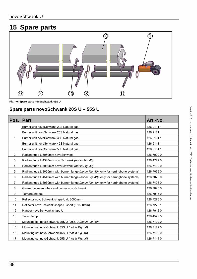
15 Spare parts
Fig. 40: Spare parts novoSchwank 45S U
Spare parts novoSchwank 20S U – 55S U
Pos. Part Art.-No.
1
Burner unit novoSchwank 20S Natural gas 126 9111 1
Burner unit novoSchwank 25S Natural gas 126 9121 1
Burner unit novoSchwank 35S Natural gas 126 9131 1
Burner unit novoSchwank 45S Natural gas 126 9141 1
Burner unit novoSchwank 55S Natural gas 126 9151 1
2 Radiant tube L 3050mm novoSchwank 126 7020 0
3 Radiant tube L 4540mm novoSchwank (not in Fig. 40) 126 4722 0
4 Radiant tube L 5950mm novoSchwank (not in Fig. 40) 126 7199 0
5 Radiant tube L 3050mm with burner flange (not in Fig. 40) [only for herringbone systems] 126 7069 0
6 Radiant tube L 4540mm with burner flange (not in Fig. 40) [only for herringbone systems] 126 7070 0
7 Radiant tube L 5950mm with burner flange (not in Fig. 40) [only for herringbone systems] 126 7408 0
8 Gasket between tubes and burner novoSchwank 126 7048 0
9 Turnaround box 126 7015 0
10 Reflector novoSchwank shape U (L 3000mm) 126 7276 0
11 Reflector novoSchwank shape U short (L 1500mm) 126 7276 1
12 Hanger novoSchwank shape U 126 7012 0
13 Tube clamp 126 4529 5
14 Mounting set novoSchwank 20S U / 25S U (not in Fig. 40) 126 7102 0
15 Mounting set novoSchwank 35S U (not in Fig. 40) 126 7129 0
16 Mounting set novoSchwank 45S U (not in Fig. 40) 126 7103 0
17 Mounting set novoSchwank 55S U (not in Fig. 40) 126 7114 0
12 13

novoSchwank U
39
Ver
sion
012
no
vo s
hape
U i
nter
natio
nal
18/1
5 T
echn
ical
spe
cific
atio
n su
bjec
t to
chan
ge
Fig. 41: Spare parts burner unit
Spare parts burner unit novoSchwank 20S U – 55S U
The reducing nipple ¾” to ½” installed on site for heaters 45S U and 55S U has to be used again (postion 5)
Pos. Part Art.-No. 1 Spark igniter with ionisation cable 127 0246 9
2 Ignition wiring with plug 126 7021 0
3 Control Microgas P25 126 7495 0
4 Pressure switch DL1E with damping nozzle 192 0217 8
5 Spare part gas valve cpl. premounted – replacement HONEYWELL for SIT novoSchwank 20S U – 55S U / with cable valve – in cardboard
126 7532 1
6 Spare part gas valve HONEYWELL for HONEYWELL 1-stage VK 4105C 192 0765 0
7 Burner cup aluminum complete novoSchwank 20S U – 35S U 126 7239 0
8 Burner cup steel complete novoSchwank 45S U natural gas, 55S U propane 126 7219 0
9 Burner cup steel complete novoSchwank 55S U natural gas 126 7468 0
10 Fan complete with venturi novoSchwank 20S U – 55S U with transport lock 126 7684 0
11 Fan complete with venturi novoSchwank 55S U - valid only for heaters sold up to May 2015 126 7053 0
12 Gas filter complete ½“ (for novoSchwank 20S U – 35S U) (not in Fig. 41) 192 0756 0
13 Gas filter complete ¾“ (for novoSchwank 45S U – 55S U) (not in Fig. 41) 192 0757 9
14 Spare part kit for gas filter ½“ (not in Fig. 41) 192 0758 0
15 Spare part kit for gas filter ¾“ (not in Fig. 41) 192 0759 0

novoSchwank U
40
Version
012novo
shapeU
international18/14
Technicalspecification
subjecttochange
16 EC type examination certificate

novoSchwank U
41
Ver
sion
012
no
vo s
hape
U i
nter
natio
nal
18/1
5 T
echn
ical
spe
cific
atio
n su
bjec
t to
chan
ge

novoSchwank U
42
Version
012novo
shapeU
international18/15
Technicalspecification
subjecttochange
17 EC declaraction of conformity