notice to bidders improvements to treatment unit no. …
TRANSCRIPT

NOTICE TO BIDDERS
IMPROVEMENTS TO TREATMENT UNIT NO. 3 AT THE OCEAN PINES WASTEWATER TREATMENT PLANT - WORCESTER COUNTY, MARYLAND
The Worcester County Commissioners are currently accepting sealed bids for the improvements associated with Treatment Unit No. 3 at the Ocean Pines Wastewater Treatment Plant (OPWWTP) for the Worcester County Department of Public Works - Water and Wastewater Division. Bid Packages and Bid Forms may be obtained online under the "Bids" drop-down menu in the lower right hand side of the home page at www.co.worcester.md.us or by calling the Commissioners' Office at 410-632-1194 to request a package by mail. Sealed bids will be accepted until 1:00 PM, Monday, June 8, 2020 in the Office of the County Commissioners at Room 1103 - Worcester County Government Center, One West Market Street, Snow Hill, Maryland 21863. Bids will be opened on Tuesday, June 9, 2020 at 1:00 PM EST and results will be promptly posted under the "Bids" drop-down menu of the County Website. Envelopes shall be marked "Bid for Improvements - OPWWTP Treatment Unit No. 3" in the lower left-hand corner. After opening, bids will be forwarded to the Department of Public Works for tabulation, review and recommendation to the County Commissioners for their consideration at a future meeting. In awarding the bid, the Commissioners reserve the right to reject any and all bids, waive formalities, informalities and technicalities therein, and to take whatever bid they determine to be in the best interest of the County considering lowest or best bid, quality of goods and work, time of delivery or completion, responsibility of bidders being considered, previous experience of bidders with County contracts, or any other factors they deem appropriate. All inquiries shall be directed to John Ross, Deputy Director of Public Works, at 410-641-5251, extension 2412.

MARCH 2020
VICINITY MAPSCALE: 1"=10 MILES
LOCATION MAPNOT TO SCALE
© COPYRIGHT 2020 GEORGE, MILES & BUHR, LLC
TITLE SHEET
PRINTS ISSUED FOR:BIDDING
OC
EAN
PIN
ES W
ATE
WA
TER
TREA
TMEN
T PL
AN
TIM
PRO
VEM
ENTS
-TR
EATM
ENT
UNIT
NO
. 3W
ORC
ESTE
R C
OUN
TY, M
ARY
LAN
D
G-1
OCEAN PINES WATEWATERTREATMENT PLANTIMPROVEMENTS -
TREATMENT UNIT NO. 3WORCESTER COUNTY, MARYLAND
GMB FILE NO. 150127-B
DRAWING INDEX
g:\P
roje
cts\
2015
\150
127-
b ae
ratio
n di
ffuse
r uni
t no.
3\D
raw
ings
\CU
RR
ENT\
G-1
TIT
LE S
HEE
T.dw
g, 4
/13/
2020
11:
51:1
8 AM
, mm
d, _
DW
G T
o PD
F.pc
3

© COPYRIGHT 2020 GEORGE, MILES & BUHR, LLC
OCEAN PINESWASTEWATER
TREATMENT PLANTSITE PLAN
PRINTS ISSUED FOR:BIDDING
OC
EAN
PIN
ES W
ATE
WA
TER
TREA
TMEN
T PL
AN
TIM
PRO
VEM
ENTS
-TR
EATM
ENT
UNIT
NO
. 3W
ORC
ESTE
R C
OUN
TY, M
ARY
LAN
D
C-1
CONSTRUCTION NOTES
TYPICAL MIXER POWER CONNECTION MODIFICATIONS
© COPYRIGHT 2020 GEORGE, MILES & BUHR, LLC
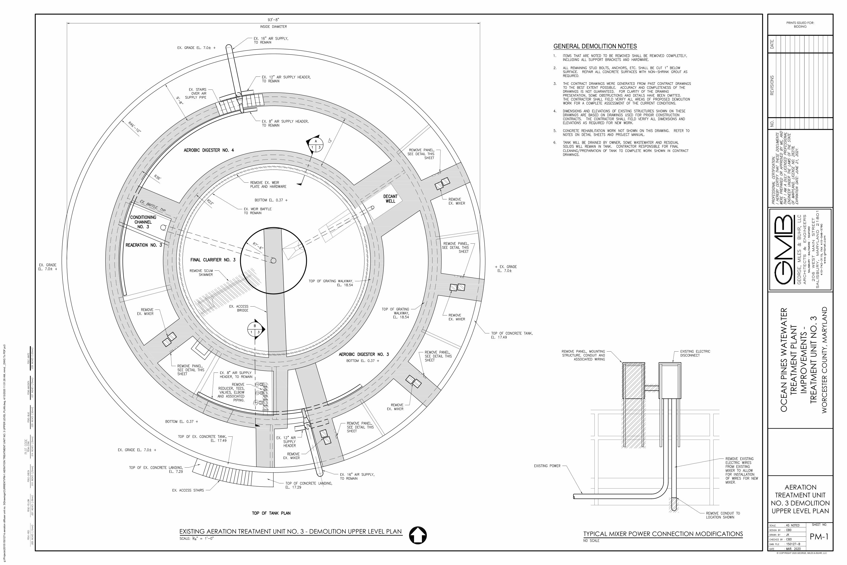
AERATIONTREATMENT UNIT
NO. 3 DEMOLITIONUPPER LEVEL PLAN
PRINTS ISSUED FOR:BIDDING
OC
EAN
PIN
ES W
ATE
WA
TER
TREA
TMEN
T PL
AN
TIM
PRO
VEM
ENTS
-TR
EATM
ENT
UNIT
NO
. 3W
ORC
ESTE
R C
OUN
TY, M
ARY
LAN
D
PM-1EXISTING AERATION TREATMENT UNIT NO. 3 - DEMOLITION UPPER LEVEL PLAN
GENERAL DEMOLITION NOTES
g:\P
roje
cts\
2015
\150
127-
b ae
ratio
n di
ffuse
r uni
t no.
3\D
raw
ings
\CU
RR
ENT\
PM-1
AER
ATIO
N T
REA
TMEN
T U
NIT
NO
. 3 U
PPER
LEV
EL P
LAN
.dw
g, 4
/13/
2020
11:
51:2
8 AM
, mm
d, _
DW
G T
o PD
F.pc
3

© COPYRIGHT 2020 GEORGE, MILES & BUHR, LLC
AERATIONTREATMENT UNIT
NO. 3 DEMOLITIONLOWER PLAN
PRINTS ISSUED FOR:BIDDING
OC
EAN
PIN
ES W
ATE
WA
TER
TREA
TMEN
T PL
AN
TIM
PRO
VEM
ENTS
-TR
EATM
ENT
UNIT
NO
. 3W
ORC
ESTE
R C
OUN
TY, M
ARY
LAN
D
PM-2
GENERAL DEMOLITION NOTES
LEGEND
EXISTING AERATION TREATMENT UNIT NO. 3 - DEMOLITION LOWER LEVEL PLAN
g:\P
roje
cts\
2015
\150
127-
b ae
ratio
n di
ffuse
r uni
t no.
3\D
raw
ings
\CU
RR
ENT\
PM-2
AER
ATIO
N T
REA
TMEN
T U
NIT
NO
. 3 D
EMO
LITI
ON
LO
WER
PLA
N.d
wg,
4/1
3/20
20 1
1:51
:34
AM, m
md,
_D
WG
To
PDF.
pc3

™
© COPYRIGHT 2020 GEORGE, MILES & BUHR, LLC
DEMOLITIONSECTIONS AND
DETAILS
PRINTS ISSUED FOR:BIDDING
OC
EAN
PIN
ES W
ATE
WA
TER
TREA
TMEN
T PL
AN
TIM
PRO
VEM
ENTS
-TR
EATM
ENT
UNIT
NO
. 3W
ORC
ESTE
R C
OUN
TY, M
ARY
LAN
D
PM-3
LEGEND
SECTION
SECTION
SECTION
SECTION
TYPICAL CONCRETE WALL REHABILITATION PREPARATION DETAIL
CLARIFIER SQUEEGEE REMOVAL DETAIL
g:\P
roje
cts\
2015
\150
127-
b ae
ratio
n di
ffuse
r uni
t no.
3\D
raw
ings
\CU
RR
ENT\
PM-2
AER
ATIO
N T
REA
TMEN
T U
NIT
NO
. 3 D
EMO
LITI
ON
LO
WER
PLA
N.d
wg,
4/1
3/20
20 1
1:51
:37
AM, m
md,
_D
WG
To
PDF.
pc3
TYPICAL MIXER POWER CONNECTION MODIFICATIONS
SECTION
SECTION
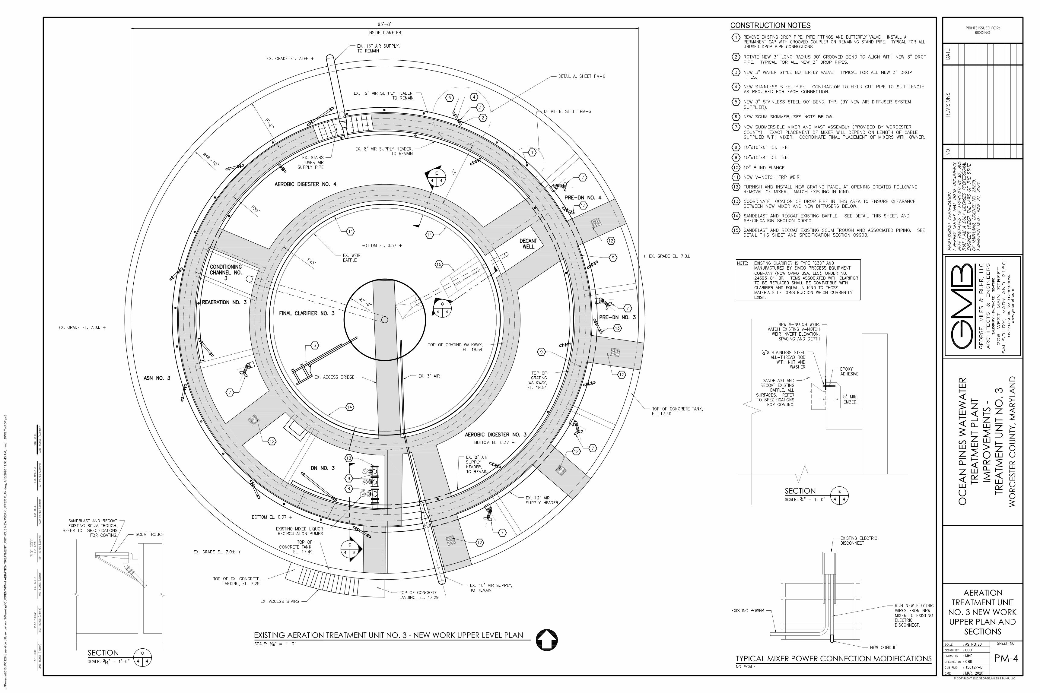
CONSTRUCTION NOTES
EXISTING AERATION TREATMENT UNIT NO. 3 - NEW WORK UPPER LEVEL PLAN
© COPYRIGHT 2020 GEORGE, MILES & BUHR, LLC
AERATIONTREATMENT UNIT
NO. 3 NEW WORKUPPER PLAN AND
SECTIONS
PRINTS ISSUED FOR:BIDDING
OC
EAN
PIN
ES W
ATE
WA
TER
TREA
TMEN
T PL
AN
TIM
PRO
VEM
ENTS
-TR
EATM
ENT
UNIT
NO
. 3W
ORC
ESTE
R C
OUN
TY, M
ARY
LAN
D
PM-4
g:\P
roje
cts\
2015
\150
127-
b ae
ratio
n di
ffuse
r uni
t no.
3\D
raw
ings
\CU
RR
ENT\
PM-4
AER
ATIO
N T
REA
TMEN
T U
NIT
NO
. 3 N
EW W
OR
K U
PPER
PLA
N.d
wg,
4/1
3/20
20 1
1:51
:43
AM, m
md,
_D
WG
To
PDF.
pc3

EXISTING AERATION TREATMENT UNIT NO. 3 - NEW WORK LOWER LEVEL PLAN
© COPYRIGHT 2020 GEORGE, MILES & BUHR, LLC
AERATIONTREATMENT UNIT
NO. 3 NEW WORKLOWER PLAN
PRINTS ISSUED FOR:BIDDING
OC
EAN
PIN
ES W
ATE
WA
TER
TREA
TMEN
T PL
AN
TIM
PRO
VEM
ENTS
-TR
EATM
ENT
UNIT
NO
. 3W
ORC
ESTE
R C
OUN
TY, M
ARY
LAN
D
PM-5
CONSTRUCTION NOTES
g:\P
roje
cts\
2015
\150
127-
b ae
ratio
n di
ffuse
r uni
t no.
3\D
raw
ings
\CU
RR
ENT\
PM-5
AER
ATIO
N T
REA
TMEN
T U
NIT
NO
. 3 N
EW W
OR
K LO
WER
PLA
N.d
wg,
4/1
3/20
20 1
1:51
:50
AM, m
md,
_D
WG
To
PDF.
pc3

PIPE SUPPORT TYPICAL CONCRETE WALL REHABILITATION DETAIL
DETAIL ADETAIL B
SECTION D-D
SECTION
™
SECTION
MCC #5 CONCRETE EQUIPMENT PAD EXTENSION
CONSTRUCTION NOTESSECTION
© COPYRIGHT 2020 GEORGE, MILES & BUHR, LLC
NEW WORKSECTIONS AND
DETAILS
PRINTS ISSUED FOR:BIDDING
OC
EAN
PIN
ES W
ATE
WA
TER
TREA
TMEN
T PL
AN
TIM
PRO
VEM
ENTS
-TR
EATM
ENT
UNIT
NO
. 3W
ORC
ESTE
R C
OUN
TY, M
ARY
LAN
D
PM-6
SECTION
SQUEEGEE DETAIL
SECTION H-H
FLOW EQUALIZATION TANK NO.2 -TELESCOPING VALVE REHABILITATION WORK
g:\P
roje
cts\
2015
\150
127-
b ae
ratio
n di
ffuse
r uni
t no.
3\D
raw
ings
\CU
RR
ENT\
PM-5
AER
ATIO
N T
REA
TMEN
T U
NIT
NO
. 3 N
EW W
OR
K LO
WER
PLA
N.d
wg,
4/1
3/20
20 1
1:51
:53
AM, m
md,
_D
WG
To
PDF.
pc3
© COPYRIGHT 2019 GEORGE, MILES & BUHR, LLC
Frazer, Pennsylvania
(610
) 407-4
100
Keystone
E N
G I
N E
E R
I N
G G
R O
U P
kegi.net
3/2/2020
OCEAN PINESWASTEWATER
TREATMENT PLANTCOVERSHEET
WO
RCES
TER
CO
UNTY
, MA
RYLA
ND
E-0
WORCESTER COUNTY, MARYLAND
MARCH 2020
OCEAN PINES WASTEWATER TREATMENT PLANTMCC No. 5 REPLACEMENT
OC
EAN
PIN
ES W
AST
EWA
TER
TREA
TMEN
T PL
AN
TA
ERA
TION
IMPR
OV
EMEN
TS -
TREA
TMEN
T UN
IT N
O. 3
© COPYRIGHT 2019 GEORGE, MILES & BUHR, LLC
Frazer, Pennsylvania
(610
) 407-4
100
Keystone
E N
G I
N E
E R
I N
G G
R O
U P
kegi.net
3/2/2020
OCEAN PINESWASTEWATER
TREATMENT PLANTELECTRICAL
SITE PLAN
WO
RCES
TER
CO
UNTY
, MA
RYLA
ND
E-1
N
OC
EAN
PIN
ES W
AST
EWA
TER
TREA
TMEN
T PL
AN
TIM
PRO
VEM
ENTS
-TR
EATM
ENT
UNIT
NO
. 3
8'
3'-712"
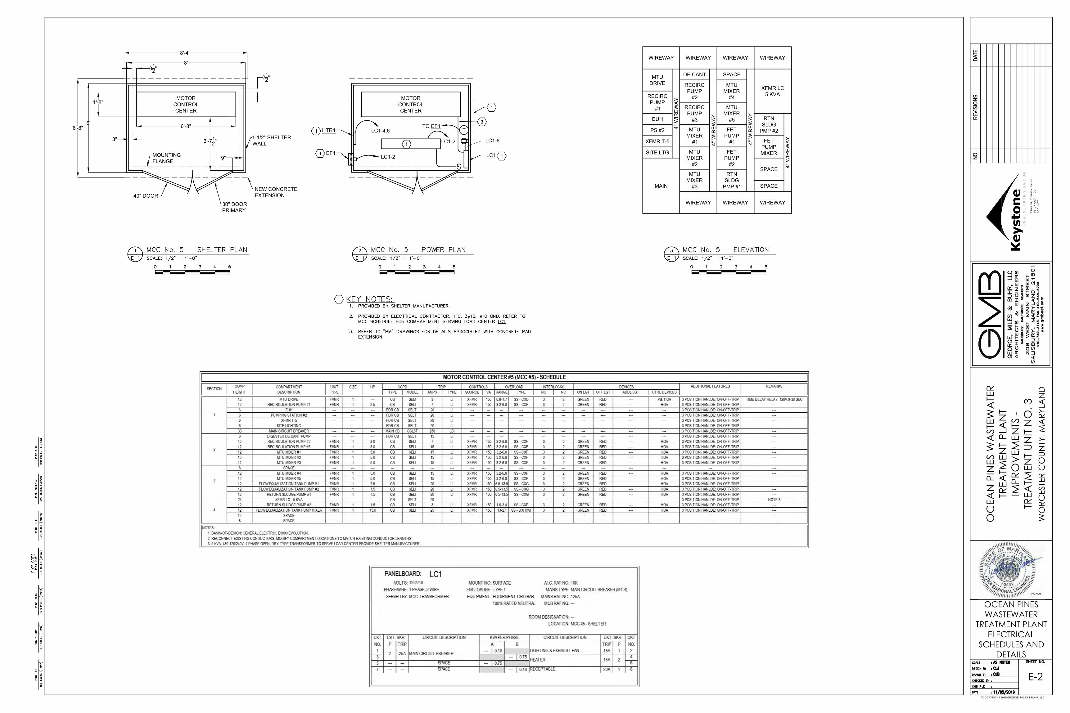
MOTORCONTROLCENTER
3"
312"
212"
6'-8"
MOUNTINGFLANGE
1-1/2" SHELTERWALL
30" DOORPRIMARY
40" DOOR
9"
NEW CONCRETEEXTENSION
8'-4"
6'-8"
MOTORCONTROLCENTER
LC1-2
6'
LC1
LC1-8
LC1-4,6HTR1
EF1LC1-2
1'-8"
TTO EF1
WIREWAY
EUH
PS #2
XFMR T-5
SITE LTG
MAIN
WIREWAY WIREWAY WIREWAY
WIREWAY WIREWAY WIREWAY
MTUDRIVE
RECIRCPUMP
#1
RECIRCPUMP
#2
RECIRCPUMP
#3
MTUMIXER
#1
MTUMIXER
#2
MTUMIXER
#3
MTUMIXER
#4
MTUMIXER
#5
FETPUMP
#1
FETPUMP
#2
RTNSLDG
PMP #1
RTNSLDG
PMP #2
FETPUMPMIXER
DE CANT SPACE
4" W
IREW
AY
4" W
IREW
AY
4" W
IREW
AY
4" W
IREW
AY
SPACE
XFMR LC5 KVA
SPACE
© COPYRIGHT 2019 GEORGE, MILES & BUHR, LLC
Frazer, Pennsylvania
(610
) 407-4
100
Keystone
E N
G I
N E
E R
I N
G G
R O
U P
kegi.net
3/2/2020
OCEAN PINESWASTEWATER
TREATMENT PLANTELECTRICAL
SCHEDULES ANDDETAILS
WO
RCES
TER
CO
UNTY
, MA
RYLA
ND
E-2
OC
EAN
PIN
ES W
AST
EWA
TER
TREA
TMEN
T PL
AN
TIM
PRO
VEM
ENTS
-TR
EATM
ENT
UNIT
NO
. 3


150127.B 00010 - 1
REQUEST FOR PROPOSAL
WORCESTER COUNTY PUBLIC WORKS OCEAN PINES WASTEWATER TREATMENT PLANT
IMPROVEMENTS - TREATMENT UNIT NO. 3
TABLE OF CONTENTS
TITLE PAGE 00100 Notice to Bidders ...................................................... 00100-1 00300 General Conditions ................................................... 00300-1 to 00300-10 1. Purpose 1
2. Scope of Work and Technical Requirements 1
3. Proposals from Bidders 1
4. Award of Agreement 2
5. Award or Rejection of Proposals 2
6. Contractor Communication, Questions and Clarification 2
7. Withdrawal 2
8. Proposal Postponement and Addenda 3
9. Cancellation of RFP 3
10. Incurred Expenses 3
11. Confidential Information 3
12. Proposal Rejection/Reservations 3
13. Deviations from Specifications 4
14. Verification of Registration and Tax Payment 4
15. Acceptance of Terms and Conditions 4
16. Acceptance of Proposal Content 4
17. Exceptions 5
18. Qualified Contractors 5
19. Project Information 5
20. Procedures 5
21. Labor and Procurement Requirements 5
22. Contract 5

150127.B 00010 - 2
23. Non-Collusion Certification 5
24. Billing and Payment 6
25. Indemnity 6
26. Insurance Requirements 6
27. Certificate of Insurance 9
28. Interpretation – Maryland Law Prevails 9
29. Protest Procedures 9
30. Worcester County Equal Employment Opportunity Clause 9
31. The Americans with Disabilities Act 9
32. Employment of Aliens 9
33. Cooperative Purchasing 10 00400 Bid Form ................................................................... 00400-1 to 00400-2 01040 Coordination ............................................................. 01040-1 to 01040-2 01100 Summary of Work ..................................................... 01100-1 to 01100-3 01150 Measurement and Payment ...................................... 01150-1 to 01150-4 01300 Submittals ................................................................. 01300-1 to 01300-4 01500 Construction Facilities & Temporary Controls ........... 01500-1 to 01500-4 01700 Contract Closeout ..................................................... 01700-1 to 01700-5 03300 Cast In Place Concrete ............................................. 03300-1 to 03300-10 03730 Concrete Rehabilitation ............................................. 03730-1 to 03730-5 09900 Painting ..................................................................... 09900-1 to 09900-10 11040 Equipment General Provisions ................................. 11040-1 to 11040-5 11236 Diffused Aeration System ......................................... 11236-1 to 11236-5 11287 Weir Plates and Accessories .................................... 11287-1 to 11287-3 15100 Process Piping, Valves And Appurtenances ............. 15100-1 to 15100-13
150127.B 00100 - 1
SECTION 00100
NOTICE TO BIDDERS
WORCESTER COUNTY PUBLIC WORKS OCEAN PINES WASTEWATER TREATMENT PLANT
IMPROVEMENTS - TREATMENT UNIT NO. 3 The Office of the County Commissioners of Worcester County is accepting sealed bids for the improvements associated with Treatment Unit No. 3 at the Ocean Pines, Maryland Wastewater Treatment Plant. Bid Packages and Bid Forms are available for downloading on the Worcester County Website www.co.worcester.md.us. Bids will be accepted until 1:00 p.m., Monday, June 8, 2020, in the Office of the County Commissioners, Worcester County Government Center, One West Market Street, Room 1103, Snow Hill, MD 21863, at which time they will be opened and publicly read aloud. Sealed envelopes will be marked “Bid for Improvements - Treatment Unit No. 3” in the lower left-hand corner. The work will consist of improvements associated with Treatment Unit No. After opening, bids will be forwarded to the Public Works Department for tabulation, review, and recommendation to the County Commissioners for their consideration at a future meeting. In awarding the bid, the Commissioners reserve the right to reject any and all bids, waive formalities, informalities and technicalities therein, and to take whatever bid they determine to be in the best interest of the County considering lowest or best bid, quality of goods and work, time of delivery or completion, responsibility of bidders being considered, previous experience of bidders with County contracts, or any other factors they deem appropriate. All inquiries shall be directed to John Ross at 410-641-5251.

This Page Intentionally Left Blank

150127.B 00300 - 1
SECTION 00300
GENERAL CONDITIONS
WORCESTER COUNTY PUBLIC WORKS OCEAN PINES WASTEWATER TREATMENT PLANT
IMPROVEMENTS - TREATMENT UNIT NO. 3 1. Purpose The purpose of this Request for Proposal (RFP) is to obtain proposals from qualified firms to complete improvements associated with Treatment Unit No. 3 located at the Ocean Pines Wastewater Treatment Plant for the Worcester County Department of Public Works, Water and Wastewater Division. 2. Scope of Work and Technical Requirements
2.1. Summary of Work – Refer to Section 01100. 2.2. Coordination – Refer to Section 01040
2.3. Bid Items – Refer to Section 00400. 2.4 Schedule All work shall be completed based on the following schedule: No later than 150 calendar days after the Notice-To-Proceed (NTP). Owner anticipates a NTP date of September, 2020.
3. Proposals from Bidders
3.1. Proposals Proposal must include the business address and telephone number and identify one (1) or more individual authorized to sign the contract. The Proposal must be signed by such individual(s). 3.2. Submission of Proposals Bidders shall submit one (1) paper copy of Proposal in a sealed envelope labeled “Bid for Treatment Unit #3”. Proposals must be received no later than June 8, 2020 at 1:00 PM local time at the following location: The Office of the County Commissioners Worcester County Government Center One West Market Street, Room 1103 Snow Hill, MD 21863
150127.B 00300 - 2
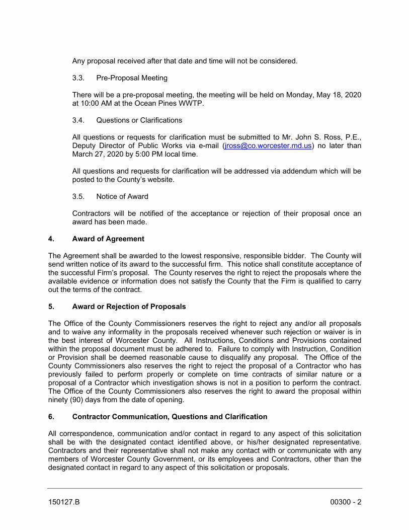
Any proposal received after that date and time will not be considered. 3.3. Pre-Proposal Meeting There will be a pre-proposal meeting, the meeting will be held on Monday, May 18, 2020 at 10:00 AM at the Ocean Pines WWTP. 3.4. Questions or Clarifications All questions or requests for clarification must be submitted to Mr. John S. Ross, P.E., Deputy Director of Public Works via e-mail ([email protected]) no later than March 27, 2020 by 5:00 PM local time. All questions and requests for clarification will be addressed via addendum which will be posted to the County’s website. 3.5. Notice of Award Contractors will be notified of the acceptance or rejection of their proposal once an award has been made.
4. Award of Agreement The Agreement shall be awarded to the lowest responsive, responsible bidder. The County will send written notice of its award to the successful firm. This notice shall constitute acceptance of the successful Firm’s proposal. The County reserves the right to reject the proposals where the available evidence or information does not satisfy the County that the Firm is qualified to carry out the terms of the contract. 5. Award or Rejection of Proposals The Office of the County Commissioners reserves the right to reject any and/or all proposals and to waive any informality in the proposals received whenever such rejection or waiver is in the best interest of Worcester County. All Instructions, Conditions and Provisions contained within the proposal document must be adhered to. Failure to comply with Instruction, Condition or Provision shall be deemed reasonable cause to disqualify any proposal. The Office of the County Commissioners also reserves the right to reject the proposal of a Contractor who has previously failed to perform properly or complete on time contracts of similar nature or a proposal of a Contractor which investigation shows is not in a position to perform the contract. The Office of the County Commissioners also reserves the right to award the proposal within ninety (90) days from the date of opening. 6. Contractor Communication, Questions and Clarification All correspondence, communication and/or contact in regard to any aspect of this solicitation shall be with the designated contact identified above, or his/her designated representative. Contractors and their representative shall not make any contact with or communicate with any members of Worcester County Government, or its employees and Contractors, other than the designated contact in regard to any aspect of this solicitation or proposals.
150127.B 00300 - 3
7. Withdrawal After proposals have been officially opened, no proposal may be withdrawn for a period of sixty (60) days, and then only by written notification delivered to the Office of the County Commissioners prior to the date and time set for proposal opening. However, proposals may be modified or withdrawn by the Contractor’s authorized representative in person or by written or facsimile notice. If proposals are modified or withdrawn in person, the authorized representative shall make her/his verifiable identity known and shall sign a receipt for the proposal. Written or facsimile notices shall be received in the office and labeled “Office of the County Commissioners” no later than the exact proposal due date and time. Pre-notifications on the bid proposal shall not be construed to comply with this requirement. 8. Proposal Postponement and Addenda Worcester County reserves the right to revise or amend the specifications up to the time set for final written questions. Such revisions and amendments, if any, shall be announced by an addendum to this solicitation. Acknowledgements of the receipt of all amendments will be required from all Contractors receiving this RFP. If the revisions and amendments require, in the sole judgment of Worcester County, changes to substance of the proposal, the proposal due date may be postponed by such number of days as in the opinion of Worcester County shall enable Contractors to revise their proposals. In any case, the proposal due date will be at a time not less than five (5) business days after the issue date of the last addendum, and the new addendum will include announcement of the new proposal due date, if applicable. 9. Cancellation of RFP The Office of the County Commissioners may cancel this RFP, in whole or in part, whenever this action is determined to be advantageous to the County or otherwise in its best interest. 10. Incurred Expenses The Office of the County Commissioners will not be responsible for any costs incurred by any Contractor in preparing and submitting a proposal, or in performing any other activities relative to this procurement. 11. Confidential Information Worcester County Government will in good faith endeavor not to disclose proprietary information, trade secrets and confidential, commercial and financial information submitted in any proposal. Any such proprietary information, trade secrets or confidential commercial and financial information that a Contractor believes should be exempted from disclosure must be specifically identified and marked as such. Blanket-type identification or designation by a Contractor of whole pages or sections as containing proprietary information, trade secrets or confidential commercial and financial information will not necessarily assure confidentiality. Specific proprietary information, trade secrets or confidential commercial and financial information must be clearly identified as such.

150127.B 00300 - 4
12. Proposal Rejection / Reservations The Office of the County Commissioners reserves the right to waive minor informalities or irregularities in any proposal received that do not go to the heart and central purpose of the proposal or do not prejudice other Contractors. The Office of the County Commissioners further reserves the right to reject any or all proposals and to award the contract in its entirety, or in part, whichever in its opinion best serves the interest of the County. The County may waive minor differences in the specifications, provided these differences do not violate the specifications intent, nor materially affect the operation for which the item or items are being purchased, nor increase estimated maintenance and repair cost to the County. The County shall have the right to take such steps as it deems necessary to determine the stability of the Contractor to perform the work; the apparent low Contractor, upon request, shall furnish all such information and data for this purpose. 13. Deviations from Specifications Specifications contained herein reflect Worcester County’s preference (or are noted as illustrative) as to dimensions, materials and major components of this procurement. The Contractor must note, in bold face type, in any proposal that deviates from any specification, the text where each deviation occurs, and the Contractor must state an explanation of the deviation. 14. Verification of Registration and Tax Payment Before a corporation can do business in the State of Maryland, it must be registered with the Department of Assessments and Taxation, State Office Building, Room 803, 301 West Preston Street, Baltimore, MD 21201. It is strongly recommended that any potential Contractor complete registration prior to the due date for receipt of proposals. A Contractor’s failure to complete registration with the Department of Assessments and Taxation may disqualify an otherwise successful Contractor from final consideration and contract award. 15. Acceptance of Terms and Conditions By submitting a proposal in response to this RFP, a Contractor shall be deemed to have accepted all the terms, conditions and requirements set forth in this RFP and hereby offers to provide services and results as specified in this Worcester County Request for Proposal, unless otherwise clearly noted and explained in its proposal as described. 16. Acceptance of Proposal Content The content of this RFP and the Proposal of the successful Contractor will be included by reference in any resulting contract. All prices, terms and conditions in the proposal shall remain fixed and valid for 60 days after the closing date. This period may be extended by mutual agreement between the Contractor and Worcester County. 17. Exceptions The Contractor shall furnish a separate statement on company letterhead giving a complete description of all exceptions to the terms, conditions and specifications, referencing the section of the RFP being addressed.
150127.B 00300 - 5
Failure to furnish the statement will mean that the proposer agrees to meet all requirements of the RFP. 18. Qualified Contractors In order to be considered a qualified Contractor, the Contractor submitting a proposal in response to this Request for Proposal must be able to completely perform the services requested and all of the requirements of this Request for Proposal in a timely, prompt and satisfactory manner. By submitting a response to this solicitation, each Contractor certifies that it can legally do business in the State of Maryland, and represents that it is not in arrears in the payments of any obligations due and owing the State of Maryland, including the payment of taxes and employee benefits, and that it shall not become so in arrears during the term of the Contract if selected for Contract award. 19. Project Information All existing County data to be used and additional data or information developed by the firm for this project is and shall be the sole property of the County. The firm may not assert any right of ownership to any of the data or information resulting from this project, including text files, mapping data, databases, spreadsheets, etc. the County shall have full rights for use and transfer of any and all data or information. Any transfer, sale, distribution, loan or offering for use of existing data or data and information developed by the firm for this project, in whole or in part, to any person or entity outside of Worcester County Government is prohibited without prior written consent by the County. 20. Procedures The extent and character of the work to be done by the Contractor shall be subject to the general control and approval of the County’s authorized representative. The Contractor shall not comply with requests and/or orders issued by other than the representatives acting within their authority for the County. 21. Labor and Procurement Requirements The Contractor and all subcontractors of the Contractor shall conform to the labor laws of the State of Maryland and all other laws, ordinances, and legal requirements affecting the work in Worcester County, Maryland. 22. Contract The proposal with respect to all items accepted and all papers accompanying the same, the scope of services and the Standard Services Agreement, and other papers and documents referred to in any of the foregoing shall constitute the formal contract, unless otherwise specified between the successful Contractor or individual and the Office of the County Commissioners.

150127.B 00300 - 6
23. Non-Collusion Certification By submission of this proposal, the firm hereby certifies:
1. The fees in this Proposal have been arrived at as a result of an independent business judgment, without collusion, consultation, communication, agreement or otherwise for the purpose of restricting competition, in any manner relating to prices, with any other person, partnership or corporation;
2. Unless otherwise required by law, the fees which have been set forth in this
Proposal have not directly or indirectly been knowingly disclosed by the firm, prior to proposal “opening,” to any other person, partnership or corporation; and,
3. No attempt has been made, or will be made, by the firm to induce any other
person, partnership or corporation to submit, or not to submit, a Proposal for the purpose of restricting competition.
24. Billing and Payment Each bill shall carry the purchase order number of Worcester County. All invoices will be paid within thirty (30) days unless any item thereon is questioned, in which event payment will be withheld pending verification of the amount claimed and the validity of the claim. 25. Indemnity The successful bidder shall protect, hold free and harmless, defend and indemnify the County Commissioners of Worcester County, including its officers, agents, volunteers and employees, from all liability, penalties, cost, law suits, damages, expenses, death of any person or damage to property of any kind, which injury, death or damage arises out of, or is any way connected with the performance of the work under this contract. The Contractor’s / vendor’s obligation to defend and indemnify shall survive the termination of the contract. 26. Insurance Requirements A. Workers’ Compensation and Employer’s Liability Insurance:
The successful bidder shall maintain coverage during the entire life of the Contract: I. Contractor shall obtain Workers’ Compensation Insurance as required by statute.
The Workers’ Compensation coverage shall cover a sole proprietor, all employees, partners, officers, members, leased employees and any other person working for or with the Contractor. Contractor shall provide County a certificate of Workers' Compensation insurance before beginning the Work. If Contractor fails to carry Workers' Compensation insurance, or its policy lapses during the Work for any reason, Contractor shall indemnify County against any claims against County's Workers' Compensation insurance policy. Contractor shall also be responsible to reimburse the County for any audit premiums that result from any lapses in Contractor’s policy and

150127.B 00300 - 7
II. Employer’s Liability Insurance with limits of:
$100,000 accident/$100,000 disease each employee/and $500,000 disease policy limit If any portion of the project is subcontracted, the successful bidder shall require all of the Subcontractors to maintain the same policy limits in workers’ compensation and employer’s liability insurance required for the successful bidder.
B. Commercial General Liability Insurance:
The successful bidder’s Commercial General Liability policy shall be on an occurrence basis and shall include: Policy limits not less than $1,000,000 each occurrence and $2,000,000 general aggregate. Coverage for Premises/Operations, Actions of Independent Contractors, Products/Completed Operations, Contractual Liability and Personal Injury. Coverage shall include explosion, collapse, or underground (XCU) hazards as applicable to classification. Products or Completed Operations coverage shall be purchased for at least five (5) years after the completion of the contract and shall cover the operations performed under the contract
C. Business Automobile Liability:
The successful bidder shall provide insurance coverage for any owned, hired, or non-owned motor vehicles. The policy limits shall not be less than $1,000,000 combined single limit or $1,000,000 bodily injury and $1,000,000 property damage each accident. The policy will provide $1,000,000 of uninsured or underinsured motorist coverage and include contractual liability coverage.
D. General Insurance Requirements for all Insurance Policies:
The County shall be added as an additional insured to the general liability policy with the following wording: “The County, its officers, agents, employees and volunteers are additional insured with regards to the General Liability policy for work performed under terms of the contract.” The successful bidder’s Certificate(s) of Insurance shall include the following:
I. A cancellation provision requiring a written forty-five (45) day notice of
cancellation or non-renewal will be furnished to the County by the successful bidder’s insurance carrier(s) or insurance agent(s). Therefore, the words "endeavor to" and "but failure to mail such notice shall impose no obligation or liability of any kind upon the company, its agents or representatives" are to be

150127.B 00300 - 8
eliminated from the cancellation provision of standard ACORD certificates of insurance.
II. A Project description in the body of the form.
The successful bidder shall provide the County with Certificate of Insurance, within seven (7) days of bid award notification, evidencing the coverage required above. Insurance shall be procured from insurance companies authorized to do business in the State of Maryland and acceptable to Worcester County. The insurers shall have an A.M. Best’s insurance rating of A- or better and a financial size of Class VII or better unless the County Risk Manager grants specific approval for an exception.
E. Bidders Insurance Requirement:
Commercial General or Other Required Liability Insurance – “Claims Made” Basis: I. If Commercial General or other liability insurance purchased by the successful
bidder has been issued on a “claims made” basis, the Contractor must comply with the following additional conditions. The limits of liability and the extensions to be included as described in the Check List remain the same. The Contractor must either:
(a) Agree to provide certificates of insurance evidencing the above
coverages for a period of five (5) years after final payment for the contract. Such certificates shall evidence a retroactive date, no later than the beginning of the Contractors or subcontractors’ work under this contract; or
(b) Purchase an extended (minimum five (5) years) reporting period endorsement for the policy or policies in force during the term of this contract and evidence the purchase of this extended reporting period endorsement by means of a certificate of insurance or a copy of the endorsement itself.
(c) All construction projects exceeding $1,500,000.00 will require a five (5) year extended reporting period (tail).
(d) All deductibles for all insurance requirements are subject to County approval.
(e) Contractors Pollution Liability or equivalent coverage extension within the General Liability policy. Policy limits not less than $1,000,000 each occurrence and $2,000,000 aggregate. This policy must provide coverage for:
Bodily injury, sickness, disease, sustained by any person, including death; Property damage, including physical injury to or destruction of tangible property including the resulting loss of use thereof; cleanup costs, the loss of use of tangible property that has not been physically injured or destroyed including diminution of value and Natural Resources damages; Defense costs including costs, charges and expenses incurred in the investigation, adjustment or defense of claims;

150127.B 00300 - 9
Contractual liability coverage, eg. Coverage for liability assumed by the named insured under a written contract or agreement; The full scope of the named insureds operating as found within the scope of work for the contract; The policy must provide coverage for claims made or occurrence based on policy form; The policy must insure contractual liability, be Primary and Non-Contributory and name County as an additional insured; The policy cannot contain exclusions for work performed by subcontractors.
27. Certificate of Insurance Prior to job starting dates Contractors must provide the County with a Certificate of Insurance for all required coverage. The certificate must show: Contractor's agent's name, insurance carrier's name, the County as additionally insured, name of Contractor, policy number, effective and expiration dates of Contractor's policy. The Contractor shall not begin to perform work on the project until certificate is received by the Office of the County Commissioners. 28. Interpretation – Maryland Law Prevails The contract resulting from this solicitation shall be construed under the laws of the State of Maryland. Mandatory provision for all contracts unless otherwise authorized by the Office of the County Commissioners of Worcester County 29. Protest Procedures Protests of bid awards must be received by the County in writing by certified mail not later than ten (10) calendar days after bidders have been notified or should have known of the contract award. Protests must be fully supported with adequate technical data, test results, or other pertinent information to support the protest. At a minimum, this must include the name and address of the protestor; identification of the project for which the protest is being filed; a statement of the reasons for the protest; supporting exhibits, evidence or documents to substantiate the protest; and a statement of the ruling desired from the county. The decision of the county shall be final except in instances of violations of federal law or regulations; and/or violations of the county’s protest procedure or the failure of the county to review a complaint or protest. 30. Worcester County Equal Employment Opportunity Clause Worcester County expects that the Contractor not discriminate against any employee or applicant for employment because of race, creed, color, national origin, sex or age. 31. The Americans with Disabilities Act
150127.B 00300 - 10
The Americans with Disabilities Act applies to the Worcester County Government and its programs, services, activities, and facilities. 32. Employment of Aliens All bidders, as a condition to doing business with the County, are required to comply with all applicable laws and regulations relating to the employment of aliens. If it is determined that a bidder fails to comply with any such employment laws or regulations during the course of any County projects, such failure may constitute material breach of the bidder’s contractual relationship with the County, and the County may take all reasonable steps to terminate its relationship with the bidder. 33. Cooperative Purchasing The County reserves the right to extend all of the terms, conditions, specifications, and unit or other prices of any contract resulting from this bid to any and all public bodies, subdivisions, school districts, community colleges, colleges, and universities including non-public schools. This is conditioned upon mutual agreement of all parties pursuant to special requirements, which may be appended thereto. The supplier/contractor agrees to notify the issuing body of those entities that wish to use any contract resulting from this bid and will also provide usage information, which may be requested. The County assumes no authority, liability, or obligation, on behalf of any other public or non-public entity that may use any contract resulting from this bid. All purchases and payment transactions will be made directly between the Contractor and the requesting entity. Any exceptions to this requirement must be specifically noted in the bid/proposal response.
150127.B 00400 - 1
SECTION 00400
BID FORM
WORCESTER COUNTY PUBLIC WORKS OCEAN PINES WASTEWATER TREATMENT PLANT
IMPROVEMENTS - TREATMENT UNIT NO. 3 TO: COMMISSIONERS OF WORCESTER COUNTY COUNTY GOVERNMENT CENTER 1 WEST MARKET STREET, RM. 1103 SNOW HILL, MARYLAND I have received the construction documents titled Improvements - Treatment Unit NO.3. I have also received Addenda Nos. , and have included their provisions in this Proposal. I have examined the bid documents and submit the following bid:
SCHEDULE A – LUMP SUM PRICES BID
Item No.
Description Lump Sum Price
A1
Improvements – Treatment Unit No.3
Subtotal Schedule A
$

150127.B 00400 - 2
SCHEDULE B – UNIT PRICE BIDS
Item No.
Description Size Unit Estimated Quantity
Bid Unit Price
Estimated Bid Price
B1 Concrete Demolition and Repair
-- SF 1,000
B2 Miscellaneous Existing Reinforcing Prep and Anti-Corrosion Coating
-- LF 20
B3 Chemical Injection Repair of Leaking Crack
-- LF 50
Subtotal Schedule B $
TOTAL BASE BID (SCHEDULE “A” + “B”):
Total Base Bid Price (Number): ________________________ Total Base Bid Price (in Words): ________________________
BID MUST BE SIGNED TO BE VALID Date: _______________ Signature: _______________________________________ Typed Name: _______________________________________ Title: _______________________________________ Firm: _______________________________________ Address: _______________________________________
_______________________________________ Phone: _______________________________________
150172.B 01040 - 1
SECTION 01040 COORDINATION PART 1 - GENERAL 1.01 INTERFACE WITH EXISTING FACILITIES A. Treatment Unit No. 3 will be removed from service by the Owner prior to the commencement of work by the Contractor. The Owner will drain the tank and remove the majority of sludge/trash (if present). Contractor will be responsible for cleaning of tank as necessary to ready for replacement of aeration system and completion of other work shown in the Contract Documents. Contractor will also be responsible for removal of wash water and residual wastewater/sludge; disposal will be permitted at the WWTP site. Contractor to coordinate with Owner regarding disposal location. B. All operational functions in the existing wastewater facilities shall be performed by the WWTP personnel, or their designated representatives, unless otherwise authorized. 1.02 MAINTENANCE OF TRAFFIC A. The roadways interior to the WWTP shall remain unobstructed during work operations when practical. Temporary closings of interior roadways can be arranged with the approval of WWTP personnel. The Contractor should make every effort to keep at least one lane of traffic open at all times. B. It shall be the responsibility of the Contractor not to interfere with or create any hazards to traffic. No equipment or material will be stored or permitted to stand where traffic must be maintained. It shall be the responsibility of the Contractor to control dust on all roads, drives and walkways on which traffic is being maintained. C. The Contractor must provide access, at all times, for the plant operation to existing treatment units. 1.03 CONTRACTOR'S SEQUENCE OF CONSTRUCTION A. The Contractor is responsible for all construction sequencing. The Contractor shall, in accordance with Section 01300 – SUBMITTALS, submit and obtain approval of his construction schedule. Acceptance of this plan by the Engineer or the Owner denotes only lack of objection at the time and in no way implies that the Engineer or the Owner guarantees that particular sequence of construction as proposed by the Contractor will in fact work. Also, any approval given is done so with the stipulation that all work done shall comply with the plans and specifications.
150172.B 01040 - 2
B. As construction proceeds, should the Contractor's sequence of construction cause operational problems that were unforeseen at the time of approval, the Engineer or the Owner reserves the right to withdraw the previous approval and require the Contractor to submit and obtain approval of an amended sequence of construction. The sequence of construction will be updated monthly. PART 2 – PRODUCTS (Not used) PART 3 – EXECUTION (Not used)
* END OF SECTION *

150127.B 01100 - 1
SECTION 01100 SUMMARY OF WORK PART 1 – GENERAL 1.01 DESCRIPTION OF WORK A. The site of the Ocean Pines Wastewater Treatment Plant is located on Shore Lane in Ocean Pines, Maryland. B. Treatment Unit No. 3 (TU3) at the Ocean Pines Wastewater Treatment Plant is an activated sludge process capable of biological nitrogen reduction connected to an aerobic digester. The system was constructed in the 1990’s. The plant capacity was expanded around 2004 using the Bardenpho Process after which time TU3 is not required to be online year-round. The aeration diffusers and associated components will be replaced. This contract serves to select a general contractor (hereinafter referred to as “INSTALLER”) to remove and replace the aeration system and to also complete the other work shown and described within the Contract Documents. As part of the work the INSTALLER will need to clean the interior of existing 8-inch and 12-inch air supply headers to remove any debris that if left in place may damage the new aeration system. C. The OWNER previously selected and entered into a contract with an aeration supplier (hereinafter referred to as “SUPPLIER”) to define its scope of supply and services and to pre-purchase these items. 1.03 GUARANTEE A. INSTALLER shall furnish the County a 24-month guarantee of workmanship and
materials, dating from time of delivery of materials to the site and shall make good any defects which may occur during that period.
1.04 FIELD CONDITIONS AND MEASUREMENTS A. INSTALLER shall field verify all dimensions of existing treatment unit and other items pertinent to the scope of supply and installation of the aeration diffusers. B. Should the INSTALLER discover any discrepancy between actual conditions and those indicated, which prevent following good practice or the intent of the Contract Drawings and Specifications, he shall notify the Engineer and shall not proceed with his work until he has received instructions from the Engineer.
150127.B 01100 - 2
C. No claims shall be made for extra payment or extensions of Contract completion time if the Contractor fails to notify the Engineer of any discrepancy before proceeding with the aspect of the work. 1.05 CONTRACT DOCUMENTS A. All work shall be completed in accordance with the Contract Documents. B. The Contract Drawings and Specifications are complementary. However, should a dispute arise as to which shall govern, the Contract Specifications will apply. C. Any discrepancy between the "General Conditions" and the "Technical Specifications," the Technical Specifications shall govern. 1.06 WORK PERIOD A. The Contractor will be allowed to work 40 hours per week Monday through Friday, 52 weeks per year. B. The Contractor shall not work on Saturday, Sunday, or any Holidays observed by the Owner unless prior approval is secured from the Owner. If the Contractor desires to work longer than eight (8) hours per day or if he desires to work on weekends, he must first obtain the written permission of the Owner and Engineer. PART 2 – PRODUCTS (Not used) PART 3 – EXECUTION 3.01 GENERAL REQUIREMENTS A. Contractor shall be solely responsible for the means, manpower, methods, techniques, sequences and procedures of construction. B. Construction work under this contract shall be performed in a manner that minimizes impact to normal facility operations. C. All operations of existing equipment, valves and gates required to perform the work shall be done by the owner. The Owner or his designated agent shall be informed in writing at least 24 hours, or longer where specified, in advance of the need to operate existing equipment, valves or gates or other actions which could affect facility operations.

150127.B 01100 - 3
D. The Owner will be responsible for taking existing facilities off-line and draining existing tanks, except as noted below. 1. Final wash down and cleaning, including removal of solids, of these tanks
to the degree necessary to perform work within the tanks shall be the responsibility of the Contractor.
E. Contractor shall furnish any temporary access required, including ladders, platforms, grating, walkways and awaits, which shall comply with OSHA laws, for necessary plant operations. F. No extra payment shall be made for any labor, materials, tools, equipment or temporary facilities required during the construction of facilities. All costs therefore shall be considered to have been included in the price bid of the Proposal.
* END OF SECTION *

150127.B 01150 - 1
SECTION 01150 MEASUREMENT AND PAYMENT PART 1 - GENERAL 1.01 DESCRIPTION A. Payment for the work completed under this Contract will be made at the lump sum and allowance prices bid, which prices shall include the furnishing of all labor, tools, equipment and materials and the performance of all work required to complete the project as indicated and specified in accordance with all requirements of the Project Manual and to the entire satisfaction of the Engineer. B. It is intended that all work shown on the Contract Drawings and included in the specifications is to be paid for under the items listed in the proposal form. The absence from the proposal form of bid items for any specific category of work shall be interpreted as meaning that the cost of such work, accomplished as defined by the Contract Documents, shall be included in the prices bid for related items listed in the proposal form. Should the Contractor feel that the cost for any item of work has not been defined by a Bid Form payment item, he shall include the cost for that work in some other applicable bid item, so that his proposal for the project reflects his total price for completing the work in its entirety. C. The prices stated in the proposal(s) include all costs and expenses for taxes, labor, equipment, materials, commissions, transportation charges and expenses, patent fees and royalties, labor for handling materials during inspection, together with any and all other costs and expenses for performing and completing the work as shown on the Drawings and specified herein. The basis of payment for an item at the lump sum or unit price shown in the proposal(s) shall be in accordance with the description of that item in this Section. D. All removal, relocation and disposal work as indicated in the Contract Documents, and/or as necessary to complete the proposed work shall be performed at no additional cost to the Owner. Cost of all removal, relocation and disposal work shall be included in the price bid. E. For the unit price Items included in the Bid, the Contractor will be paid for the actual quantity of the authorized work done or material furnished under each item of the proposal, at the unit price bid for such item. The quantities for payment under this Contract shall be determined by actual measurement of the completed items, in place, ready for service and accepted by the Owner, in accordance with the General Conditions.

150127.B 01150 - 2
F. Payments during the course of the work for lump sum items will be made on the basis of percentage completion of the work items listed in the schedule of values for each lump sum item. The Schedule of Values shall be prepared by the Contractor and submitted to the Engineer and shall serve as a breakdown of the lump sum bid for the purpose of arriving at a basis for the monthly estimate. The Schedule shall add up to 100% of the Lump Sum bid. G. All incidental minor and miscellaneous items, work and materials for which no specific lump sum item is shown and which are necessary to complete the work and to maintain and/or repair the work, shall be done and furnished by the Contractor without extra charge. 1.02 LUMP SUM BID ITEMS A. Bid Items A1: Lump Sum Bid - Improvements Treatment Unit No. 3
1. Payment for improvement to Treatment Unit No. 3 shall be made at the lump sum price bid for Bid Item A1.
2. The lump sum prices bid for improvement to Treatment Unit No. 3 shall include all work related to MCC 5 replacement together with fiberglass shelter, fine and coarse bubble aeration system installation (system pre-purchased by Owner), aeration system piping modifications, submersible mixer installation (pre-purchased by Owner) and associated electrical work, replacement of secondary clarifier components, replacement of clarifier weir, improvements to RAS pump piping and pump removal system, replacement of various valves, telescoping valve rehabilitation, demolition of various items, painting of new work and miscellaneous items, and installing all other appurtenances on the site specified or detailed.
1.03 UNIT PRICE BID ITEMS A. Bid Item B1: Concrete Demolition and Repair
1. Measurement for this item will be made on the actual number of square feet of material removed and replaced. Revisions to the repair quantity in the bid form may be required after the Engineer has determined the extent of area to be removed and replaced based on his field observation after Treatment Unit No. 3 has been drained. Contractor is responsible for final cleaning of tank surface for all areas where it is determined that concrete demolition and repair work will occur. The Contractor will be paid for the demo of the concrete and the installation of the silica fume enhanced repair mortar as specified.
2. Payment for this item will be made at the per square foot price bid for “Concrete Demolition and Repair” which price shall be full compensation for all labor materials, tools, equipment and incidentals required to perform

150127.B 01150 - 3
this work in accordance with the specifications. Unit price bid is done so with the understanding that the MINIMUM payment quantity for this unit price bid item shall be 500 square feet.
B. Bid Item B2: Miscellaneous Existing Reinforcing Prep and Anti-Corrosion
Coating
1. Measurement for this item will be made on the actual number of lineal feet of rebar repaired. This item covers the cost of preparing the rebar and coating any existing rebar after the demo of the concrete structure has been performed. The Contractor will be paid for the surface preparation and installation of the anti-corrosion coating as specified.
2. Payment for this item will be made at the per linear foot price bid for “Miscellaneous Existing Reinforcing Prep and Anti-Corrosion Coating” which price shall be full compensation for all labor materials, tools, equipment and incidentals required to perform this work in accordance with the specifications.
C. Bid Items B3: Chemical Injection Repair of Leaking Crack
1. Measurement for this item will be made on the actual number of lineal feet of leaking crack repaired. This item covers the cost of injecting and repairing cracks in the precast structure to eliminate water intrusion at the structure. The Contractor will be paid for the injection repair as specified.
2. Payment for this item will be made at the per linear foot price bid for “Chemical Injection Repair of Leaking Crack” which price shall be full compensation for all labor materials, tools, equipment and incidentals required to perform this work in accordance with the specifications.
1.04 PAYMENT A. After the award of the Contract, the Contractor will develop an itemized breakdown of the bid amount according to specific work activities. At the end of each pay period, the Contractor shall submit to the Owner or his authorized representative for approval an invoice showing percent complete for each item on the breakdown. B. With each Application for Payment, the Contractor shall submit a Form of Waiver and Release of Mechanic's Liens relating to the work for which they are to be paid with the proceeds of such Application of Payment. C. The Contractor shall promptly pay each Subcontractor (including suppliers, laborers and materialmen) performing labor or furnishing material for the work upon receipt of payment from the Owner out of the amount paid to the Contractor on account of the work for each subcontractor, supplier, laborer, or materialmen, the amount to which said subcontractor is entitled, reflecting the percentage actually retained, if any, from payments to the Contractor on account of such work.

150127.B 01150 - 4
D. The Owner may, on request and at his discretion, furnish to any subcontractor, if practicable, information regarding the percentages of completion or the amounts applied for by the Contractor and the action taken thereon by the Owner on account of work done by such subcontractor. E. The Owner shall not have any obligation to pay nor to see to the payment of any monies to any subcontractor except as may otherwise be required by law. F. No progress payment nor any partial or entire use of occupancy of the Project by the Owner shall constitute an acceptance of any work which is not in accordance with the Contract Documents. 1.05 PAYMENTS WITHHELD A. The Owner may decline to pay all or any part thereof or, because of subsequent observations, it may nullify the whole or any part of any payment previously issued, to such extent as may be necessary in its opinion to protect the Owner from loss because of:
1. Defective work not remedied. 2. Third party claims filed or reasonable evidence indicating probable filing of
such claims. 3. Failure of the Contractor to make payments properly to subcontractors or
for labor, material or equipment. 4. Reasonable evidence that the work cannot be completed for unpaid
balance of the Contract Sum. 5. Damage to the Owner or another Contractor. 6. Reasonable evidence that the work will not be or has not been completed
within the Contract time. 7. Failure to carry out the work in accordance with the Project Manual. 8. Cancellation, material change or lapse of required insurance as specified
in the Contract Documents.
PART 2 – PRODUCTS
(Not used) PART 3 – EXECUTION (Not used)
* END OF SECTION *

150127.B 01300 - 1
SECTION 01300 SUBMITTALS PART 1 - GENERAL 1.01 SHOP DRAWINGS, PRODUCT DATA AND SAMPLES A. Shop drawings are generally defined as all fabrication and erection drawings, diagrams, brochures, schedules, bills or material and other data prepared by the INSTALLER, his subcontractors, suppliers or manufacturers which illustrate the manufacturer, fabrication, construction and installation of the work, or a portion thereof. B. All costs necessary for compliance with the requirements of this Section of the specifications shall be included under the lump sum and/or unit price bid. C. Detailed shop drawings, data, literature for fabricated materials or equipment to be incorporated in the work shall be submitted to the Engineer for review for general compliance with the contract documents before fabrication. The SUPPLIER shall obtain and check manufacturer's shop drawings, certified prints and other pertinent data for conformance with all requirements of the Plans and Specification and in ample time to permit satisfactory progress of the work. After the completion of such checking and verification by the INSTALLER, the INSTALLER shall sign or stamp such drawing, which stamp shall state as follows:
Checked by (INSTALLER's Name)
Signed by
(Checker's Name)
Specification Section No. Signed by
D. All data, drawings and correspondence from subcontractors, manufacturers or suppliers shall be routed through the INSTALLER. The Engineer shall review only such data and details as are transmitted to him by the INSTALLER. All correspondence from the INSTALLER to the Engineer shall refer to the appropriate section of these specifications containing the subject matter of the inquiry. E. All shop drawings shall be in conformity with all requirements of the plans and specifications. All shop drawings except diagrams, brochures, schedules and illustrations shall be to an appropriate scale, no smaller than 1/8 inch = 1 foot 0 inches, and shall give all dimensions necessary for installation and incorporation in the work.

150127.B 01300 - 2
All shop drawings shall be accurate and complete, showing outline and section views, details, materials, accessories, appurtenances and related items. Shop drawings showing piping and conduit systems shall incorporate sufficient views to show all fittings and specialties including locations and spacing of hangers and supports. Piping and/or conduit systems 3-inches in diameter and smaller may be shown as single line. Equipment and specialties installed within and/or connected to piping and conduit systems shall be cross-referenced to equipment and specialty shop drawings by shop drawing identification number, manufacturer name, catalog or model number and equipment numbers shown on the plans.
F. The INSTALLER shall submit to the Engineer a minimum of FIVE (5) copies of shop drawings and approval data. The Engineer will retain two (2) copies of each submittal and return one (1) copy to the INSTALLER. The Engineer's notation of the action taken will be noted on all of the returned copies. At the time of each submission, the Contractor shall call to the Engineer's attention, in writing, any deviations that the shop drawings may have from the requirements of the Plans and Specifications. G. Upon review by the Engineer of the above drawings, lists, samples and other data the same shall become a part of the Contract, and the fabrications furnished shall be in conformity with the same, provided that the review of the above drawings, lists, specifications sample or other data shall in no way release the SUPPLIER from his responsibility for the proper fulfillment, by any fabrication, or the requirements of this Contract. H. Corrections or comments made on the shop drawings during the Engineer's review do not relieve the SUPPLIER AND INSTALLER from compliance with the requirements of the drawings and specifications. This check is only for review of general conformance with the design concept of the project and general compliance with the information given in the Contract Documents. The INSTALLER is responsible for confirming and correlating all quantities and dimensions, selecting fabrication processes and techniques of construction, and in performing his work in a safe manner. If the shop drawings deviate from the Contract Documents, the SUPPLIER shall advise the Engineer of the deviations, in writing accompanying the shop drawing, including the reasons for the deviations, and shall request deviation from the Contract Documents. I. The shop drawings are intended to be utilized by the SUPPLIER and INSTALLER for additional fabrication, assembly and erection data. The shop drawings do not change or supersede the Plans and Specifications except in specific cases when the INSTALLER requests in writing and receives approval in writing for a deviation from the Plans and Specification. The INSTALLER’S request for a change shall give, in detail, the specific change requested and shall state the reason for the change. Changes requested by the INSTALLER and approved by the Engineer shall not be construed to include approval of any change except the changed details specifically requested and approved.
150127.B 01300 - 3
J. The SUPPLIER and INSTALLER’S attention is specifically directed to the fact that no work shall be fabricated, nor equipment or materials ordered, nor any construction performed, prior to approval by the Engineer of show drawings applicable thereto. Construction performed in violation of this requirement will be neither approved no certified for payment until applicable shop drawings have been submitted and approved. If the Engineer so directs, the Contractor shall disassemble and remove any such construction performed prior to approval by the Engineer of shop drawings applicable thereto, and the Contractor will be allowed no additional compensation nor extension of contract time. If any equipment or materials are ordered by the Contractor prior to submission and approval of shop drawings he does so at his own risk. K. It shall be the responsibility of the Contractor to make all the necessary changes in other items, which result from deviations or changes requested by the Contractor and approved by the Engineer, so that all items perform the requirements and intent of the Contract Documents. L. After review by the Engineer, shop drawings shall be returned to the Contractor marked as follows: APPROVED, APPROVED AS NOTED, REVISE AND RESUBMIT or REJECTED. Unapproved shop drawings (i.e., REVISE AND RESUBMIT or REJECTED) shall be returned to the Contractor for necessary modifications: only two (2) copies of unapproved shop will be returned. M. Timing of Submittals:
1. Make submittals promptly and in such sequence as to cause no delay in the Work.
2. In scheduling, allow 10 working days for Engineer's review following receipt of the submittal.
1.02 OPERATION AND MAINTENANCE MANUALS A. The Contractor shall furnish the Engineer two (2) sets of a complete instruction manual for installation, operation, and maintenance for all equipment at the time of material delivery to the site. B. Manuals shall include a complete and detailed listing describing routine maintenance for each time interval: daily, weekly, monthly, quarterly, semi–annually and yearly. Routine maintenance shall include adjustments, inspections, calibrations, etc. C. The following items shall also be submitted:
1. Name of manufacturer with address and phone number for service and parts.
2. Name, address and phone number of the nearest service representative for the manufacturer.

150127.B 01300 - 4
3. A list of spare parts including part number and other information needed to order parts.
D. Where an O&M manual contains a written warranty or guarantee, it shall be certified to meet the minimum length of time and requirements defined in the RFP. 1.03 RECORD DRAWINGS A. During the progress of the job, the Contractor shall keep a careful record at the job site of all changes and corrections to the information shown on the Drawings. The Contractor shall enter such changes and corrections on one set of Contract Drawings immediately. The record drawings shall indicate, in addition to all interior changes and corrections, the actual location referenced from two permanently fixed surface structures of all subsurface utilities installed or uncovered by him. At the time of beneficial occupancy of each facility involved under the Contract, the Contractor shall submit to the Engineer one set of record drawings showing the aforementioned data. If the Contractor fails to maintain the record drawings as required herein, final payment, with respect to the Contract as a whole, will be withheld until proper record drawings have been furnished to the Engineer. B. The Contractor shall keep one copy of all Project Manual and approved Shop Drawings at the site in good order and annotated to show all changes made during the construction process. These shall be available to the Engineer and shall be delivered to him upon completion of the Project. 1.04 SUBMISSION OF MANUFACTURER'S CERTIFICATES A. The SUPPLIER shall submit Manufacturer's Certificates for the installation of the aeration diffuser system. B. Such Manufacturer's Certificates shall state that the equipment has been installed under either the periodic supervision of the manufacturer's authorized representative, that it has been adjusted and initially operated in the presence of the manufacturer's authorized representative and that it is operating in accordance with the specified requirements, to the manufacturer's satisfaction. PART 2 – PRODUCTS (Not used)
PART 3 – EXECUTION (Not used)
* END OF SECTION *

150127.B 01300 - 5

150127.B 01500 - 1
SECTION 01500 CONSTRUCTION FACILITIES AND TEMPORARY CONTROLS PART 1 - GENERAL 1.01 FIELD OFFICE A. Not applicable 1.02 ELECTRIC POWER A. It shall be the obligation and responsibility of the General Contractor to provide and maintain temporary facilities for furnishing light and power necessary for operations under the General Contract and to make all necessary arrangements therefore, including all required connections, ordering the meter, and paying all fees and inspection charges. If power is obtained from the plant, it will be metered and the Contractor will be charged for the power used. B. The General Contractor shall make the temporary power facilities available to any and all approved Subcontractors, for their use in connection with their Contracts, and may charge each Subcontractor for such service an amount not to exceed a fraction of the cost of the project. Removal of temporary facilities shall be by the General Contractor. The installation and meters shall remain until need for same by each Subcontractor has ceased or until completion of the General Contract. 1.03 TEMPORARY HEAT AND VENTILATION A. It shall be the obligation and responsibility of the General Contractor to provide and maintain temporary heat by means of portable electric, oil or gas-fired units. The General Contractor shall provide and pay for all fuel and electricity used in the temporary facilities and shall provide proper smoke pipes or other means to prevent smoke or smudge from marking up walls, ceilings or other parts of equipment. B. Should the temporary heating facilities require electric service, the General Contractor shall provide the necessary wiring and power. C. After their installation and testing, the permanent heating system facilities may be used for temporary heat, it shall be the responsibility of the General Contractor to guarantee the heating system for a period of two years following final acceptance of the General Contract or beneficial occupancy of the General Contract, whichever comes first. It also shall be the responsibility of the General Contractor to replace all filters before the final acceptance of the General Contract.

150127.B 01500 - 2
D. It shall be the responsibility of the General Contractor to repair any damage to heating and ventilating equipment suffered as the result of use by the General Contractor. 1.04 WATER SUPPLY A. Owner will make available potable water; Contractor will pay the cost of potable water used. The Contractor will be responsible for any temporary piping and connections required to obtain either water type. Contractor shall not use potable water to fill and test process tanks and equipment. Contractor shall provide temporary pumps and piping to use effluent water from the existing treatment plant for this purpose 1.05 SANITARY FACILITIES A. The Contractor shall provide and maintain approved sanitary facilities for the full term of the Contract. 1.06 FIELD CONDITIONS AND MEASUREMENTS A. INSTALLER shall field verify all dimensions of existing treatment unit and other items pertinent to the scope of supply and installation of the aeration diffusers. B. Should the INSTALLER discover any discrepancy between actual conditions and those indicated, which prevent following good practice or the intent of the Contract Drawings and Specifications, he shall notify the Engineer and shall not proceed with his work until he has received instructions from the Engineer. C. No claims shall be made for extra payment or extensions of Contract completion time if the Contractor fails to notify the Engineer of any discrepancy before proceeding with the aspect of the work. 1.07 PROTECTION OF PERSONS AND PROPERTY A. The Contractor shall be responsible for initiating, maintaining and providing supervision of safety precautions and programs in connection with the work including, but not limited to, all legally required precautions and programs. B. The Contractor shall take all reasonably necessary precautions for safety of, and shall provide all reasonably necessary protection to prevent damage, injury or loss to: (1) employees on the work and other persons who may be affected thereby; (2) the work, materials and equipment to be incorporated therein; and (3) other property at or adjacent to the site. C. The Contractor shall give all notice and comply with all applicable laws, ordinances, rules, regulations, and orders of public authorities bearing on the safety of

150127.B 01500 - 3
persons and property and their protection from damage, injury or loss arising from Contractor's operations hereunder. D. The Contractor shall be liable for damage or loss (other than damage or loss to property insured under the property insurance provided or required by the Project Manual to be provided by the Owner) to property at the site to the extent caused in whole or in part by the Contractor, a Subcontractor of the Contractor or anyone directly or indirectly employed by either of them, or by anyone for whose acts they may be liable, except damage or loss attributable to the acts or omissions of the Owner, the Owner's separate contractors or anyone directly or indirectly employed by them or by anyone for whose acts they may be liable and not attributable to the fault or negligence of the Contractor. 1.08 CONTRACTOR STORAGE AND WORK AREAS A. The Contractor will be responsible for providing storage and work areas for use by the Contractor for parking of workmen's vehicles, storage of materials, tools, field offices, equipment and other items necessary for construction. The exact limits of the areas will be designated in the field by the Owner during the Pre-bid Conference. The Contractor shall be fully responsible for the security of these areas, including fencing, and other means of security. Under no circumstances will the Owner be responsible for the security of any property belonging to the Contractor, his subcontractors, or any of his work forces. B. Contractor shall maintain all staging areas including grass cutting. 1.09 SAFETY A. Precaution shall be exercised at all times for the protection of persons (including employees) and property. The safety provisions of applicable laws, building and construction codes shall be observed. Machinery and equipment shall be guarded and all hazards shall be eliminated in accordance with the safety provisions of the Manual of Accident Prevention in Construction published by the Associated General Contractors of America, to the extent that such provisions are not in contravention of applicable law. B. The Contractor shall comply with the U.S. Department of Labor, Safety and Health Regulations for Construction promulgated under the Occupational Safety and Health Act of 1970 (Public Law 91-596) and under Section 107 of the Contract Work Hours and Safety Standards (Public Law 91-54). C. Nothing in the Occupational Safety and Health Act of 1970 shall be construed to supersede or in any manner affect any workmen's compensation law or to enlarge or diminish or affect in any manner the common law or statutory rights, duties, or liabilities of employers and employees under any law with respect to injuries, diseases, or death of employees arising out of or in the course of employment.
150127.B 01500 - 4
PART 2 – PRODUCTS (Not used) PART 3 – EXECUTION (Not used)
* END OF SECTION *

150127.B 01700 - 1
SECTION 01700
CONTRACT CLOSEOUT PART 1 - GENERAL 1.01 DEFINITIONS A. Substantial Completion: The project will be considered substantially complete when all equipment and process units have been installed and tested and the treatment unit is ready to begin the treatment of wastewater. 1.02 CLEANUP A. Execute final cleaning prior to final inspection. B. Clean interior and exterior glass and surfaces exposed to view; remove temporary labels, stains and foreign substances, polish transparent and glossy surfaces, vacuum carpeted and soft surfaces. C. Clean equipment and fixtures to a sanitary condition with cleaning materials appropriate to the surface and material being cleaned. D. Clean debris from treatment unit. E. Clean site; sweep paved areas, rake clean landscaped and restored surfaces. F. Remove waste and surplus materials, rubbish, sheds, tools and construction facilities from the site. 1.03 SPARE PARTS A. Where the Specifications require spare parts to be furnished by the Contractor, said spare parts for each item of equipment shall be kept separate and tagged to identify the specific item of equipment to which they belong, shall be packaged so as to preclude damage from handling and storage, and shall be bagged or packaged together where items are small in dimension. 1.04 DELAYS AND EXTENSIONS OF TIME A. The Contractor shall not be entitled to payment or compensation of any kind from the Owner for direct, indirect or impact damages, including but not limited to costs of acceleration arising because of hindrance or delay from any cause whatsoever, whether such hindrances or delays be reasonable or unreasonable, foreseeable or

150127.B 01700 - 2
unforeseeable, or avoidable or unavoidable; provided, however, that this provision shall not preclude recovery by the Contractor of damages for hindrances or delays due solely to fraud or bad faith on the part of the Owner or his agents. B. In the event the Contractor requests an extension of the Contract Time, he shall furnish such justification and supporting evidence as the Owner may deem necessary for a determination of whether or not the Contractor is entitled to an extension of time under the provisions of the Contract. The Owner shall base his findings of fact and decision on such justification and supporting evidence and shall advise the Contractor in writing thereof. If the Owner finds that the Contractor is entitled to any extension of the Contract Time, the Owner's determination of the total number of days' extension shall be based upon the currently approved progress schedule and on all data relevant to the extension. Such data will be incorporated into the schedule in the form of a revision thereto, accomplished in a timely manner. The Contractor acknowledges and agrees that actual delays in activities or time required to accomplish change order activities which, according to the schedule, do not affect the critical path and therefore do not have any effect upon Contract completion time, will not be a basis for an extension of time. 1.06 WARRANTY AND GUARANTEE A. After the project is substantially complete and the Engineer has issued the Certificate of Substantial Completion, all guarantees and warranties shall commence. B. The Contractor warrants and guarantees to the Owner for a period of 24-months the following:
1. That all materials and equipment provided under this Contract are new, unless otherwise specified.
2. That all work is of good quality and free from faults and defects and in accordance with the requirements of the Project Manual.
3. That all equipment and systems and each and every part thereof, shall operate (with proper care and attention) in a satisfactory and efficient manner, and in accordance with the Project Manual.
4. That the Contractor shall, upon receipt of written notice from the Owner, promptly replace with workmanship and materials which comply with these Specifications, and re-execute, correct or repair, without cost to the Owner, all work which may be found to be not in accordance with the Project Manual.
5. That the guarantee obligations assumed by the Contractor under these Project Manual shall not be held or taken to be in any way impaired because of the Specifications, indication or approval by or on behalf of the Owner of any articles, materials, means, combinations of things used or to be used in the construction, performance and completion of the work, or any part thereof.

150127.B 01700 - 3
6. That no use or acceptance by the Owner of the work or any part thereof, nor any failure to use the same, nor any repairs, adjustments or corrections made by the Owner due to the Contractor's failure to comply with any of his obligations under the Project Manual, shall impair in any way the guarantee obligations of the Contractor under this Contract.
C. Contractor shall post a maintenance bond in the amount of 5% of the full contract value. D. If the Contractor fails to make repairs during the guarantee period, the Owner may cause such damaged or defective work to be repaired and made good at the cost and expense of the Contractor, including, but not limited to, compensation if required for additional professional services. The Contractor shall also bear the expenses of making good all work destroyed or damaged by the correction, removal or replacement of his defective work. 1.07 TESTING OF EQUIPMENT AND SYSTEMS A. Preliminary Testing: 1. When the Contractor has completed the installation of all equipment
including electrical appurtenances, he shall perform preliminary testing on each piece of equipment.
2. Contractor shall provide for the inspection of each piece of equipment by authorized and qualified manufacturer's representatives. These manufacturer's representatives shall verify that all equipment has been installed properly.
3. Manufacturer's representatives shall verify that the individual equipment and/or components are functioning in accordance with the Project Manual.
4. The manufacturer of each piece of equipment shall provide a manufacturer's certificate in accordance with Section 01300 - SUBMITTALS.
B. Pre-Final Testing: 1. After receipt of all manufacturer's certificates, the Contractor will be
required to perform wet tests on all pieces of equipment. 2. The Owner will provide water for pre-final testing. Contractor will be
responsible for furnishing piping and pumps as necessary to fill tanks. Contractor will also be responsible for disposing of water once tests are completed.
3. Pre-final testing shall include the actual running of equipment. This testing shall be done under the supervision of the manufacturer's representative.
4. Pre-final testing shall include operation of the system components with clear water to the Owner’s satisfaction and shall be completed prior to the final testing / plant startup.
150127.B 01700 - 4
C. Final Testing/Plant Startup: 1. Purpose and Scope: The purpose of a final test/startup period is to
operate the treatment unit to demonstrate that the work constructed in accordance with the Project Manual will operate on a continuous basis (with prescribed care). The startup period will be for a period of seven (7) calendar days.
2. Readiness to Operate: When the Contractor has substantially completed the work and when Preliminary, and Pre-Final Tests are complete, he shall notify the Engineer in writing, requesting permission to start up and requesting diversion of the wastewater flow to the treatment unit. The Engineer will respond in writing, authorizing the start up of the plant or will state reasons why the operation may not commence.
3. Actual operation of the plant will be by the Owner. However, the Contractor shall make available his personnel to correct any deficiencies that are discovered during this seven (7) day startup period.
D. Satisfactory Performance: 1. Satisfactory performance is defined as the treatment unit accepting
sewage with all equipment operating satisfactorily for a minimum of seven (7) days.
1.08 FINAL ACCEPTANCE A. Upon completion of all work under this Contract including the testing of equipment, and placing the plant in operation and operating the plant continuously for seven (7) days, the Contractor shall request, in writing, final acceptance by the Owner. B. Upon receipt of the request, the Engineer, the Owner, and the Contractor will make a Final Inspection of the Project to determine the status of completion as follows: 1. If the Engineer does not consider the Project to be complete, the Engineer
will notify the Contractor in writing of this fact, and will include the reasons why the Project is not considered complete.
2. Any items not satisfactorily completed or unsatisfactory as determined by the Engineer, shall be promptly remedied or completed.
3. Upon satisfactory correction of defects or incomplete information or work, the Engineer will certify to the Owner that the treatment unit is finally complete.

150127.B 01700 - 5
PART 2 – PRODUCTS (Not used) PART 3 – EXECUTION (Not used)
* END OF SECTION *

This Page Intentionally Left Blank

150127.B 03300 - 1
SECTION 03300
CAST-IN-PLACE CONCRETE PART 1 - GENERAL 1.01 DESCRIPTION A. The work under this section shall include cast-in-place concrete. B. Related Work Specified Elsewhere: 1. Section 01300: Submittals 2. Section 01700: Contract Closeout 1.02 QUALITY ASSURANCE A. Standards: Conform to the requirements of the American Concrete Institute (ACI) and the American Society for Testing and Material (ASTM) or as hereinafter specified, whichever is the more stringent. Comply with applicable provisions of the latest editions of referenced specifications. 1.03 SUBMITTALS A. List of materials and manufacturers for review. B. Design Mixes: Submit design mixes for classes of concrete to be used on the project for review prior to placing concrete. Each design mix shall indicate the proposed use within the structure (i.e., floor slabs, footings, tanks, etc.). Approval of the design mix and/or acceptance of the test report does not in any way relieve the Contractor of his responsibility to insure that the strength, slump and quality of the in-place concrete meets the requirements of the Project Manual.
1. Proportioning (ACI 211.1, ACI 304, ACI 350, ACI 318): Determination of strength and quality of the concrete proposed for use is the responsibility of the Contractor, established by tests made in advance of the beginning of operations, using the consistencies most suitable for the work. Unless otherwise specified, provide concrete composed of cement, fine and coarse aggregate admixture(s) and water. The exact division of the total aggregate shall be such as to produce a concrete of the greatest workability and density.

150127.B 03300 - 2
2. Strength: Minimum ultimate compressive strength at the end of 28 days shall be as outlined below, and 7-day tests not less than 70 percent of 28-day tests.
Structural Slabs 4,000 PSI
1.04 JOB CONDITIONS A. Environmental: 1. Depositing Concrete in Cold Weather (ACI 306): a. Place concrete only when temperature is at least 35ºF and rising.
Stop concrete placement in time to allow slab to be completely finished and covered before temperature drops below 35ºF.
b. Do not add salt, chemicals or other non-freezing materials to concrete. Do not use frozen materials or materials containing ice.
c. When depositing concrete at a temperature of less than 40ºF, the concrete shall have a temperature of at least 60ºF, but not more than 70ºF for not less than 5 days after placing. When necessary, heat concrete materials before mixing. Method of heating materials and protecting concrete is subject to outside temperature at a rate not faster than one degree per hour for first day and two degrees per hour thereafter, until outside temperature is reached.
PART 2 - PRODUCTS 2.01 MATERIALS A. Cement: 1. Portland Cement: ASTM C 150 Type II for Environmental Structures,
Type 1 for others or ASTM C595. a. Total Alkalis < .6% b. C3A < 7% (ASTM C 150) 2. Use of fly ash or GGBFS is recommended for durability when in direct
contact with sewage or sewage influent. 3. Only one brand and manufacturer of approved cement shall be used for
exposed concrete. B. Aggregates: ASTM C 33, ACI 304, 211.1.:
1. Fine Aggregate: Natural sand. Free of loam, clay, or foreign matter. 2. Coarse Aggregate: Free of loam, clay, or foreign matter. Crushed stone
or gravel, hard, durable pieces, free from adherent coatings. Maximum size ASTM C33, size #57. Aggregate shall be tested by ASTM C227 or ASTM C289 for alkali-reactivity.

150127.B 03300 - 3
3. Coarse Aggregate for Toppings, Slabs and Fills 3 Inches and Less in Thickness: Pea gravel 1/2 inch maximum size.
C. Water: Clean Potable Water free from injurious amounts of oils, acids, alkalis, salts, organic materials, or other substances deleterious to concrete or reinforcement.
D. Admixtures:
1. Water Reducing Admixture: ASTM C 494, Type A (Chloride free) or
ASTM C1017. One of the following or equal. a. "Plastocrete 161" by Sika Chemical; Corporation, Rockville,
Maryland. b. "WR 77" by Chem-Masters Corp., Chagrin Falls, Ohio. c. PSI by Gifford-Hill & Co., Inc., Charlotte, N.C.
2. Air-Entraining Admixture: ASTM C 260. One of the following or equal. a. "Sika-AER" by Sika Chemical Corporation, Lyndhurst, NJ 07071. b. "Adz-Air" by Chem-Masters Corp., Chagrin Falls, Ohio 44022. c. "Air-Tite" by Gifford-Hilkl & Co., Inc., Charlotte, NC 28210.
3. Accelerator/Retarder may be used only if design mixes utilizing the accelerator/retarder are submitted and accepted.
4. Do not use calcium chloride. 5. Corrosion Inhibitor Admixture for tanks in contact with wastewater – ASTM
C-494, Type C. a. Sika CNI by Sika Chemical Corporation, Lyndhurst, NJ 07071, or
equal. b. Corrosion inhibitor admixture shall be added in accordance with
manufacturer’s dosage rate recommendations. c. The following structures shall receive corrosion inhibitor admixture: (1) Mix Chamber (2) Filter Structure (entire building) (3) Aerobic Digester (all new tankage)
6. Ground Granulated Blast Furnace Slag (GGBFS) shall conform to ASTM C989. GGBFS shall only be used with ASTM C150 cement.
7. Fly ash shall be class F conforming to ASTM C618.
E. Preformed Expansion Joint Fillers: 1. Bituminous Type: ASTM D 994. 2. Nonextruding and Resilient Bituminous Types: ASTM D 1751.
F. Epoxy Adhesive for Embedding Reinforcing Steel: HILTI HY150. G. Curing Materials: Use curing materials that will not stain or affect concrete finish or lessen the concrete strength and comply with the following requirements:
1. Burlap: Use materials conforming to AASHTO M 182.
150127.B 03300 - 4
2. Sheet Materials: Use material conforming to ASTM C 171. 3. Liquid Membrane-Forming Compounds: ASTM C 309, Type 1, free of
wax or other adhesive bond breaking ingredients, such as Master Builders MASTERSEAL 66, or equal.
2.02 PROPORTIONING CONCRETE (ACI 211.1; ACI 304; ACI 318; ACI 301) A. Determination of strength quality of the concrete proposed for use is the responsibility of the Contractor, established by tests made in advance of the beginning of the operations, using the consistencies most suitable for the work. B. Unless otherwise specified, provide concrete composed of cement, fine and coarse aggregate and water. C. The exact division of the total aggregate shall be such as to produce a concrete of the greatest workability and density. D. Contents:
1. Cement:
a. Concrete for environmental structures shall have a minimum of 535 pounds of cementitious material per cubic yard. Fly ash or other pozzolans conforming to ASTM C618 shall not exceed 25% of total cementitious materials by weight.
b. GGBFS conforming to ASTM C989 shall not exceed 50% of total cementitious materials by weight.
c. Total of fly ash or other pozzolans and GGBFS shall not exceed 50% of total cementitious materials by weight.
2. Aggregates: a. Use amounts of aggregates necessary to produce a dense
workable mixture. b. Coarse aggregate size as specified for intended use.
3. Water: a. Quantity of water to be the minimum required to attain required
slumps. b. Water/cementitious material ratio not to exceed 0.42 for
environmental structures. 0.5 for others. c. Concrete exposed to weather shall be made with not more than five
(5) gallons of water per bag of cement, including the free moisture in the aggregates.
2.03 MIXING CONCRETE A. "Ready-Mixed" Concrete:
1. (ASTM C 94 and ACI 304) Certified by the supplier as to mix and strength.

150127.B 03300 - 5
2. Delivery tickets shall state strength, slump, yards, quantities of cement, aggregate and admix, if the latter is used.
3. Maintain a readily available file of tickets covering all concrete used at the site.
B. Mix concrete only as required and do not use concrete that has been mixed so long that the initial set of the concrete, as determined by tests, occurs sooner than 15 minutes after placement. C. Discharge concrete, transported in a truck mixer, into forms within 1-1/2 hours after the cement has been added to water and aggregate. D. Admixtures:
1. Provide plasticizer admixture for concrete except footings in accordance
with manufacturer's recommendations, based on the temperature at the site at the time of placement.
2. Vary quantities of plasticizer in order that slump and water and cement content of the mix remain constant for all temperatures.
3. Provide 4 ounces of plasticizer per bag of cement for concrete used to fill masonry walls.
E. Air Entrainment: All concrete shall have air entrainment of not less than 5 percent nor more than 7 percent, certified by the supplier. F. Strength:
1. Provide the minimum ultimate compressive strength at the end of 28 days
as noted hereinbefore. 2. Seven day tests shall be not less than 70 percent of 28 day tests.
G. Slump: ACI 211.1 3-1/2 inch maximum slump. PART 3 - EXECUTION 3.01 INSPECTION A. Work to receive cast-in-place concrete shall be inspected for deficiencies which would prevent proper execution of the finished work. Do not proceed with placing until such deficiencies are corrected. B. The preparation of forms; placing of reinforcing steel, conduits and sleeves; batching; mixing; placing; and curing of concrete will be subject at all times to the inspection by the Engineer.

150127.B 03300 - 6
3.02 JOINTS AND EMBEDDED ITEMS A. Construction Joints:
1. Place construction joints where indicated on the Drawings or as required.
Where not shown, the Contractor is responsible for determining the location of construction joints.
2. Secure Engineer's written approval prior to making additional or revised locations of construction joints.
B. Bond new concrete with hardened concrete as follows:
1. Roughen and clean hardened concrete of foreign matter and laitance and
saturate with water. 2. Cover the hardened concrete with a three inch layer of grout. Use grout of
same material composition and proportions of concrete being poured except coarse aggregate omitted.
3. Place new concrete on grout before it has attained its initial set. 4. Other bonding methods must be approved by Engineer.
C. When concreting is to be discontinued for more than forty-five (45) minutes and if the construction is to be horizontal, install keyways and embed dowel bars in the concrete before initial hardening. Use keyways and dowels in vertical concrete construction only when indicated or directed by the Engineer. D. Expansion Joints and Contraction Joints:
1. Install where indicated on the drawings. 2. Do not extend reinforcing or other embedded metal items through
expansion and contraction joints; except where indicated otherwise on drawings.
3.03 PRODUCT OF CONCRETE A. Ready-Mixed Concrete:
1. Batched, mixed and transported in accordance with ASTM C94. 2. Plant equipment and facilities shall conform to the Check List for
Certification of Ready Mixed Concrete Production Facilities of the National Ready Mixed Concrete Association.
3.04 PLACING A. General: Conduct placement work in accordance with ACI 304.
150127.B 03300 - 7
B. Preparation: 1. Prepare formwork in advance and remove snow, ice, water and debris
from within forms. 2. Pre-position expansion joint material, anchors and embedded items. 3. Sprinkle subgrades sufficiently to eliminate water loss from concrete.
C. Conveying: 1. Handle concrete from mixer to final deposit rapidly by methods which will
prevent segregation or loss of ingredients to maintain required quality of concrete.
2. Do not convey concrete through aluminum or aluminum alloy. 3. Do not place concrete by pumps or other similar devices without prior
written approval of Engineer.
D. Depositing: 1. Do not allow concrete to drop vertically more than 4 feet. Use elephant
trunks for depths of more than 4 feet. 2. Deposit in approximately horizontal layers of 12 to 18 inches. 3. Do not allow concrete to flow laterally more than 3 feet. 4. Make placement within sections continuously to produce monolithic unit. 5. Carry on placing at such a rate that concrete which is being integrated
with fresh concrete is still plastic. 6. Do not deposit concrete on concrete which has hardened sufficiently to
cause the formation of seams or planes of weakness within sections. 7. Do not use concrete which has partially hardened or has been
contaminated by foreign materials. 8. Do not begin placing of concrete in beams or slabs until concrete
previously placed in walls or columns has attained initial set. 9. Do not subject concrete to procedures which will cause segregation. 10. Do not bend reinforcement out of position when placing concrete. 11. Do not place concrete in forms containing standing water.
E. Consolidation: 1. Consolidate concrete by vibration, spading, rodding or other manual
methods. Work concrete around reinforcement, embedded items and into corners: eliminate all air or stone pockets and other causes of honeycombing, pitting on planes of weakness.
2. Use vibration equipment of internal type and not the type attached to forms and reinforcement.
3. Use vibrators capable of transmitting vibration to concrete in frequencies sufficient to provide satisfactory consolidation.

150127.B 03300 - 8
4. Do not leave vibrators in one spot long enough to cause segregation. Remove concrete segregated by vibrator operation.
5. Do not use vibrators to spread concrete. 6. Have sufficient reserve vibration equipment to guard against shutdown of
work occasioned by failure of equipment in operation.
F. Cold Weather Concreting: 1. Temperature of concrete delivered at the job site shall conform to the
following temperature limitations:
Minimum Concrete Temperature, Deg. F
Air temperature deg. F.
For sections with least dimension less
than 12 in.
For sections with least dimension 12
in. or greater 30 to 45 60 50 0 to 30 65 55
2. If water or aggregate is heated above 100ºF, combine water with
aggregate in the mixer before cement is added. Do not mix cement with water or with mixtures of water and aggregate having a temperature greater than 100ºF.
3. Provide equipment for heating concrete materials and protecting concrete during freezing or near-freezing weather. Do not use foreign materials or materials continuing snow or ice.
4. Surfaces which the concrete is to come in contact with must be free of frost, snow and ice.
5. Concrete placed in forms shall have a temperature of 50ºF or higher after placement. Maintain this temperature a minimum of 5 days. Provide additional time if necessary for proper curing.
6. Housing, covering or other protection used in curing shall remain intact at least 24 hours after artificial heating is discontinued. Do not place dependence on salt or other chemicals for the prevention of freezing.
7. Perform cold weather concreting work in accordance with ACI 306.
G. Hot Weather Concreting: 1. Temperature of concrete delivered at the job site shall not exceed 90ºF. 2. Cool ingredients before mixing to prevent temperature in excess of 90ºF. 3. Make provisions for windbreaks, shading, fog spraying, sprinkling or wet
cover when necessary. 4. Perform hot weather concreting work in accordance with ACI 305.

150127.B 03300 - 9
3.05 FINISHING
A. Finishes: Finish exposed concrete surfaces true and even, free from open or rough areas, depressions or projections. Bring concrete up in vertical pours to the required elevation, strike-off with a straight edge and float-finish.
1. Floated Finish: After concrete has been placed, consolidated, struck off
and leveled, do not work further until ready for floating. Begin floating when water sheen has disappeared and when the surface has stiffened sufficiently to permit the operation.
2. Smooth Rubbed Finish: Obtained by rubbing a vertical surface not later than one day after form removal. Wet surface and rub with carborundum brick or other abrasive until uniform color and texture are produced. Do not use cement grout other than the cement paste drawn from the concrete itself by the rubbing process.
3. Steel Trowel Finish: Obtained troweling after power floating shall produce a smooth surface which is relatively free of defects but which may still show some trowel marks. Perform additional trowelings by hand after the surface has hardened sufficiently. Perform final troweling when a ringing sound is produced as the trowel is moved over the surface. Thoroughly consolidate surface by hand trowel operations. Produce finished surface essentially free of trowel marks, uniform in texture and appearance, with true planes within 1/8 inch in 10 ft., as determined by a 10 ft. straightedge placed anywhere on the slab in any direction.
4. Broom or Belt Finish: Immediately after concrete has received a Floated Finish, give surface a coarse transverse scored texture by drawing a broom or burlap belt across the surface.
B. Finish Schedule:
1. Exterior of concrete structures shall receive a smooth rubbed finish.
Includes exterior of all tanks and building walls to at least one foot below finished grade.
2. Interior of concrete structures shall receive a smooth rubbed finish. Includes interior of all tanks and building walls.
3. Floors intended as walking surfaces or for reception of floor coverings and tank floors shall receive a steel trowel finish.
4. Exterior concrete walks, steps and platforms shall receive a broom or belt finish.
C. Chamfer all exposed (horizontal and vertical) concrete edges 3/4 inch. Exposed vertical concrete edges shall also be chamfered to at least one foot below finished grade.

150127.B 03300 - 10
3.06 CLEANING AND PATCHING A. After forms have been removed and concrete surfaces observed, patch bad joints, voids, stone pockets or other defective areas.
1. Chip away defective areas to a depth of not less than one inch with the
edges perpendicular to the surface. 2. Wet area to be patched and a space at least 6 inches wide entirely
surrounding it to prevent absorption of water from patching mortar. 3. Brush into surface a grout of equal parts of Portland cement and sand with
sufficient water to produce a brushing consistency, follow immediately with patching mortar.
4. Make patch of same material and of same proportions as used for the concrete, except omit coarse aggregate.
5. Amount of mixing water as little as consistent with requirement of handling and placing.
6. Retemper mortar without addition of water by allowing it to stand for a period of one hour during which time, mix with trowel to prevent settling.
7. Thoroughly compact the mortar into place and screen off as to leave the patch slightly higher than the surrounding surface. Leave undisturbed for a period of one to two hours to permit initial shrinkage before final finishing.
8. Finish patch in such manner as to match adjoining surfaces. B. In addition to patching defective areas and filling the holes, carefully remove all fins and other projections and level offsets. 3.07 CURING AND PROTECTION
A. General: Immediately after placement, protect concrete from premature drying, excessive hot or cold temperatures and mechanical injury. Curing shall be by either water curing or sealing methods in accordance with ACI 308. Cure concrete continuously for a minimum of 7 days at ambient temperatures above 40F. B. Hot Weather Curing: Set Hot Weather Concreting this Section. C. Cold Weather Curing: See Cold Weather Concreting this Section. D. Application Rate of Liquid Membrane-Forming Compounds: Compound shall restrict the loss of water to not more than 0.055 g/cm-2 of surface in 72 hours when tested in accordance with ASTM C 156. E. Do not use liquid curing compounds over floor surfaces that are to receive a liquid hardener applied to dry concrete.
* END OF SECTION *

150127.B 03730 - 1
SECTION 03730
CONCRETE REHABILITATION
PART 1 – GENERAL 1.01 SUMMARY A. This specification describes the patching or overlay of interior and/or exterior horizontal, vertical, or overhead surfaces with a pneumatically placed cementitious, silica fume portland cement mortar/concrete followed by an overlay of epoxy-modified, cementitious resurfacing mortar (leveling mortar). 1.02 QUALITY ASSURANCE A. Manufacturing qualifications: The manufacturer of the specified product shall be ISO 9001 certified and have in existence a recognized ongoing quality assurance program independently audited on a regular basis. B. Contractor qualifications: Contractor shall be a qualified in the field of concrete repair and protection with a successful track record of 5 years or more. Contractor shall maintain qualified personnel who have received product training by a manufacturer's representative. C. Install materials in accordance with all safety and weather conditions required by manufacturer or as modified by applicable rules and regulations of local, state and federal authorities having jurisdiction. Consult Material Safety Data Sheets for complete handling recommendations. 1.03 DELIVERY, STORAGE, AND HANDLING A. All materials must be delivered in original, unopened containers with the manufacturer’s name, labels, product identification, and batch numbers. Damaged material must be removed from the site immediately. B. Store all materials off the ground and protect from rain, freezing or excessive heat until ready for use. C. Condition the specified product as recommended by the manufacturer.

150127.B 03730 - 2
1.04 JOB CONDITIONS A. Environmental Conditions: Do not apply material if it is raining or snowing or if such conditions appear to be imminent. Minimum application temperature 40ºF (7ºC) and rising. B. Protection: Precautions should be taken to avoid damage to any surface near the work zone due to mixing and handling of the specified material. 1.05 SUBMITTALS A. Submit four copies of manufacturer’s literature, to include: Product Data Sheets, and appropriate Material Safety Data Sheets (MSDS). 1.06 WARRANTY A. Provide a written warranty from the manufacturer against defects of materials for a period of one (1) year, beginning with date of substantial completion of the project. PART 2 - PRODUCTS 2.01 MANUFACTURER A. Pneumatically placed cementitious, silica fume portland cement mortar/concrete
1. Sikacem 103, as manufactured by Sika Corporation. 2. Or Approved Substitute.
2.02 MATERIALS
A. Silica fume enhanced cementitious mortar:
1. The mortar shall be a blend of selected portland cements, microsilica and
specially graded aggregates. It shall be applicable for horizontal, vertical, and overhead surfaces.
2. The materials shall be non-combustible, both before and after cure. 3. The materials shall be supplied in a factory-proportioned unit. 4. The cementitious, microsilica mortar must be placeable from 1/3in. in
depth and greater.
2.03 PERFORMANCE CRITERIA A. Typical Properties of the silica fume enhanced, cementitious mortar (material and curing conditions at 71°F to 75°F, and 45% to 55% R.H.):
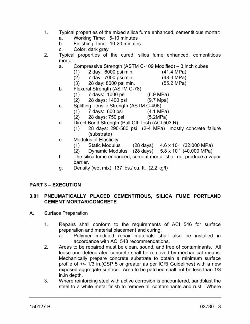
150127.B 03730 - 3
1. Typical properties of the mixed silica fume enhanced, cementitious mortar: a. Working Time: 5-10 minutes b. Finishing Time: 10-20 minutes c. Color: dark gray
2. Typical properties of the cured, silica fume enhanced, cementitious mortar:
a. Compressive Strength (ASTM C-109 Modified) – 3 inch cubes (1) 2 day: 6000 psi min. (41.4 MPa) (2) 7 day: 7000 psi min. (48.3 MPa) (3) 28 day: 8000 psi min. (55.2 MPa)
b. Flexural Strength (ASTM C-78) (1) 7 days: 1000 psi (6.9 MPa) (2) 28 days: 1400 psi (9.7 Mpa) c. Splitting Tensile Strength (ASTM C-496)
(1) 7 days: 600 psi (4.1 MPa) (2) 28 days: 750 psi (5.2MPa)
d. Direct Bond Strength (Pull Off Test) (ACI 503.R) (1) 28 days: 290-580 psi (2-4 MPa) mostly concrete failure
(substrate) e. Modulus of Elasticity
(1) Static Modulus (28 days) 4.6 x 10⁶ (32,000 MPa) (2) Dynamic Modulus (28 days) 5.8 x 10 6 (40,000 MPa)
f. The silica fume enhanced, cement mortar shall not produce a vapor barrier.
g. Density (wet mix): 137 lbs./ cu. ft. (2.2 kg/l)
PART 3 – EXECUTION 3.01 PNEUMATICALLY PLACED CEMENTITIOUS, SILICA FUME PORTLAND
CEMENT MORTAR/CONCRETE
A. Surface Preparation
1. Repairs shall conform to the requirements of ACI 546 for surface preparation and material placement and curing. a. Polymer modified repair materials shall also be installed in
accordance with ACI 548 recommendations. 2. Areas to be repaired must be clean, sound, and free of contaminants. All
loose and deteriorated concrete shall be removed by mechanical means. Mechanically prepare concrete substrate to obtain a minimum surface profile of +/- 1/3 in.(CSP 5 or greater as per ICRI Guidelines) with a new exposed aggregate surface. Area to be patched shall not be less than 1/3 in.in depth.
3. Where reinforcing steel with active corrosion is encountered, sandblast the steel to a white metal finish to remove all contaminants and rust. Where

150127.B 03730 - 4
corrosion has occurred due to the presence of chlorides, the steel shall be high pressure washed after mechanical cleaning. Prime steel with 2 coats of Sika Armatec 110 EpoCem, or approved equal, as per the technical data sheet (See Spec Component SC-201). If exposed steel has lost 20% of its cross-sectional area, add new steel (same size, grade and shape) and tie to existing with wire. New steel dowels/bars must lap a minimum of 48 bar diameters.
4. Prior to the commencement of any repair, the Contractor must consider the effect of the concrete removal on the various elements that comprise the structural frame of the building. If conditions are encountered where significant concrete removal is needed, the structure shall be shored as required to protect the structural integrity if the system before any demolition work is started. Details of shoring and formwork to be used shall be provided by the Contractor, at the Contractor’s cost. Shoring details shall be submitted for approval to the Engineer prior to commencement of work.
5. The areas of concrete to be removed shall be examined to determine if there are embedments in the concrete which may be damaged during demolition. Safe removal of existing surface-mounted items, when required, will be the responsibility of the Contractor. All items shall be reattached to the structure after completion of the repair. The Contractor shall repair damage due to negligent work at no cost to the Owner.
B. Mixing and Application
1. Material is to be applied by conventional dry spray shotcrete or wet spray
equipment. Consult TDS. 2. Placement Procedure Dry Process: At the time of application, the
substrate shall be saturated surface dry with no standing water. Apply the material in accordance with ACI 506R-90 “ Guide to Shotcrete”. Important factors during shotcreting are: the nozzle distance (2-6ft), angle to substrate (90o) and consistency of mortar. Mortar consistency should be plastic (like firm jelly), immediately after application and before set. A natural gun finish may be used. If gun finish is too rough, you may apply special finishes. Slice off excess material with a sharp-edged cutting screed 5 to 10 minutes after initial set. The surface may then be finished to your requirements: 1. Broomed for rough textured, 2. Wood-floated for a granular texture, 3. Steel-troweled for smooth surface finish. When following application with EPOXY MODIFIED CEMENTITIOUS MORTAR, finish with heavy texture for a bonding profile by means of sponge floating, wood floating, or broom finishing.
Placement Procedure Wet Process: At time of application, surface should be saturated surface dry but hold no standing water. Apply material by spraying or troweling for repairing vertical or overhead surfaces. Shoot the material perpendicular to the surface. This minimizes rebound, creates the smoothest pattern (reduces bumps) and properly encases the

150127.B 03730 - 5
rebars. The velocity of the shotcrete is sufficient if, at a distance of 18 to 24 in., the shotcrete pattern flattens out on contact with the surface and the rebars are encased. After applying the material, allow to stiffen for approx. 10 minutes before removing bumpy areas with a trowel. If another layer is desired, allow the material to reach initial set. This will take anywhere from 2-4 hours depending on mix consistency, mix and ambient temperature, wind conditions and humidity. Begin and finish a given patch on the same day.
3. As per ACI recommendations for portland cement concrete, curing is required. Moist cure with wet burlap and polyethylene, a fine mist of water or a water-based* compatible curing compound. Moist curing should commence immediately after finishing. Protect newly applied material from rain, sun, and wind, and frost until compressive strength is 70% of the 28-day compressive strength. To prevent from freezing cover with insulating material. Setting time is dependent on temperature and humidity.
*Pretesting of curing compound is recommended. 4. Adhere to all procedures, limitations and cautions for the silica fume,
polymer-modified portland cement mortar in the manufacturers current printed technical data sheet and literature.
C. For application of all products in ambient temperatures below 45 F, and above 70 F, consult with the manufacturer and comply with the recommendations of ACI 305 or 306. D. Cleaning
1. The uncured silica-fume portland cement mortar can be cleaned from
tools with water. The cured silica fume portland cement mortar can only be removed mechanically.
2. Leave finished work and work area in a neat, clean condition without evidence of spillovers onto adjacent areas.
* END OF SECTION *

This Page Intentionally Left Blank

150127.B 09900 - 1
SECTION 09900
PAINTING – PROCESS EQUIPMENT AND PIPING PART 1 – GENERAL 1.01 DESCRIPTION A. Includes all work to be painted including, but not limited to, interior of tanks, equipment, pumps, piping, valves, conduits, and other related items. B. Related Work Specified Elsewhere:
1. Section 01300: Submittals 1.02 QUALITY ASSURANCE A. Applicator Qualifications: Painting applicator shall show evidence of acceptability as a qualified applicator by the manufacturer of products specified herein. Submit such evidence with Submittals as specified herein. B. Referenced Standards: 1. Steel Structures Painting Council Surface Preparation Specifications: a. SSPC–SP1, Solvent Cleaning. b. SSPC–SP2, Hand Tool Cleaning. c. SSPC–SP6, Commercial Blast Cleaning. d. SSPC–SP7, Brush Blast Cleaning. e. SSPC–SP8, Pickling. f. SSPC–SP10, Near–White Blast Cleaning. 1.03 SUBMITTALS: A. Samples: Submit sample color chips of standard colors and samples of any intermixes required to match colors indicated. B. Schedule and Product Data: Submit paint schedule in same format as the paint schedule herein, and indicate which of the selected manufacturer's products are intended for use. Do not perform painting or coating work without Engineer's approval of submitted paint schedule. C. Certificates: Paint manufacturer's direct factory representative shall certify in writing to the Engineer painting and coating compliance with the following:

150127.B 09900 - 2
1. Factory representative's initial site inspection of conditions pertinent to painting and coating work with Contractor or his authorized painting representative.
2. Factory representative's second site inspection at completion of painting and coating work to check proper application and actual mil thickness compliance with these Specifications.
3. Certification issued to Engineer only following unacceptable painting and coating work being rectified to Engineer's satisfaction.
4. Factory representative shall make his services available to the Engineer for immediate consultation in regard to the painting and coating work, and shall make above stated inspections in the Engineer's presence.
1.04 PRODUCT DELIVERY, STORAGE, AND HANDLING A. Deliver paint materials to job site in their original unopened containers with labels intact and legible at time of use. B. Store approved materials at the job site in a suitable and designated area restricted to storage of paint and coating materials and related equipment. C. Use all means necessary to ensure safe storage and use of paint and coating materials and the prompt and safe disposal of waste. Store paint and coating products protected from weather when such products may be affected by freezing. 1.05 JOB CONDITIONS A. Field and Shop Coat Compatibility: To insure satisfactory paint and coating performance, it is a Contract requirement that products applied in the shop and field be mutually compatible. 1. Contractor shall require fabricators and equipment manufacturers to apply
shop coats that are compatible with field coats specified herein. 2. Above requirement does not apply to full factory–finished items, that is,
items having both primer and final finish coatings, except as specified in the following paragraphs.
B. Painting Factory–Finished Equipment: Equipment, such as motors, pumps and other such items, which when installed become an integral part of a system and which may be delivered fully factory–finished (that is, having finish coatings in addition to the prime coating) shall not require repainting in the field unless specifically noted otherwise, or: 1. Factory finish is unacceptable to the Engineer, that is, not having generic
type of paint or proper mil thickness to withstand corrosive atmosphere of wastewater treatment plants or is not compatible with color schedule.

150127.B 09900 - 3
2. Factory finish is damaged. 3. On factory–finished items requiring repainting, first sand existing paint to a
dull finish and then repaint in scheduled finish system for the installed location of such factory–finished items.
C. Painting Caulking Compound: Do not apply paint over caulking compound until integral solvents have been released from the compound; usually two weeks for butyl–rubber based caulking and one day for acrylic latex caulking. D. Color: 1. As selected by the Engineer or noted herein. 2. Paint equipment not furnished with a factory finish, or not finished with an
acceptable factory finish, and piping and conduits the same color as adjacent surface.
3. Final work shall match Engineer approved samples. Engineer shall select colors where not indicated or specified with no extra compensation allowed the Contractor for such.
E. Placing into Service: Do not place painted items into service until paints and coatings are fully cured (dry–hard). F. Environmental Requirements: 1. Adhere to manufacturer's data on air and surface temperature limits and
relative humidity during application and curing of coatings. 2. Do not spray apply paint when wind velocity is above 15 mph. 3. Schedule coating work to avoid dust and airborne contaminants. 4. Apply exterior finishes during daylight hours only. 5. When painting must be done in confined spaces, or because of
unfavorable ambient conditions, longer drying times will be necessary. 6. Provide supplementary ventilation such as fans and blowers in confined or
enclosed areas to carry off solvents during the evaporation stage. G. Protection: 1. Protect paint materials before, during and after application, and protect
other work and materials with drop cloths or other impervious material. 2. Clean up or otherwise remedy without additional cost, damage by paint
and coatings to public or private property.

150127.B 09900 - 4
PART 2 – PRODUCTS 2.01 ACCEPTABLE MANUFACTURERS A. Paint materials listed in the Paint Schedule are products of Tnemec Company, Inc. Equivalent products of other manufacturers may be used, subject to approval. B. Request for substitution shall include manufacturer’s literature for each product giving the name, generic type, descriptive information, solids by volume, recommended dry film thicknesses and a list of five projects where each product has been used and rendered satisfactory service. No request for substitution shall be considered that would decrease film thickness or offer a change in the generic type of coating specified. Manufacturer’s certified test reports showing that the substitute product(s) equal or exceed the performance of the specified products as outlined shall be submitted. C. Acceptable manufacturers for painting of architectural components of the building are listed in Section 09910: D. Acceptable manufacturers for concrete tank surfaces coating system:
1. Tnemec Company, Inc. 2. Or Equal. 2.02 MATERIALS A. Paints and Coatings – General 1. Acceptable products: Indicated in Schedules at the end of this section. 2. Unless otherwise indicated, provide factory-mixed coatings. When
required, mix coatings to correct consistency in accordance with manufacturer’s instructions before application. Do not dilute or thin coatings, except as instructed.
3. Do not add additives except as instructed or recommended by coating manufacturer.
4. Supply each coating material in quantity required for this section from a single production run.
5. Colors: To be selected from manufacturer’s full range of available coatings.
B. Coating Application Accessories: Specified in this section or in coating manufacturer’s application instructions, including but not limited to thinners, sealers, primers, cleaning agents, etching agents, cleaning cloths, sanding materials, and clean-up materials.

150127.B 09900 - 5
PART 3 – EXECUTION 3.01 SURFACE PREPARATION A. Ferrous Metal:
1. Shop Primed: a. Immediately before paint application, clean sand, dust, mud, dirt,
and other foreign matter from shop coat. b. Touch up damaged or destroyed shop paint. c. Surface preparation of surfaces to be touched up must be as
effective as those specified for shop painting. 2. Not Shop Primed and Submerged or Intermittently Submerged in Liquid: a. Grind smooth to a rounded contour sharp edges and welds, and
remove weld splatter. b. Except for insides of pipes, sandblast in accordance with SSPC
SP–10 or pickle in accordance with SSPC SP–8. c. After sandblasting, remove dust and spent sand from surface by
brushing or vacuum cleaning. d. Apply prime coat before surface starts to rust. e. Do not allow sandblasted surface to stand overnight before coating. 3. Not Shop Primed and Non–Submerged: a. Grind smooth to a rounded contour sharp edges and welds, and
remove weld splatter. b. Sandblast in accordance with SSPC SP–6. c. After sandblasting, remove dust and spent sand from surface by
brushing or vacuum cleaning. d. Apply prime coat before surface starts to rust. e. Do not allow sandblasted surface to stand overnight before coating. B. Galvanized Metal Including Pipes and Conduits: 1. Solvent clean in accordance with SSPC SP–1. 2. Sand clean and spot prime abraded areas 3. Etch metal using Clean N’Etch by Great Lakes Laboratories, Inc. or equal
product. Follow manufacturer’s written procedures. 4. Allow to dry before application of paint. C. Shop Bituminous Coated Pipe: Hand tool clean in accordance with SSPC SP–2. D. Polyvinyl Chloride Pipe: 1. Solvent clean using bio-degradable cleaner such as Extra Muscle by
Great Lakes Laboratories or equal and thoroughly rinse clean.

150127.B 09900 - 6
2. Sand manually or mechanically with 60-80 grit aluminum oxide sandpaper and wipe off dust residue.
3.02 APPLICATION A. General: 1. Strictly follow paint manufacturer's label instructions for mixing, thinning,
proper spreading rate and drying time. In no case shall film thickness be less than manufacturer's recommendations nor shall area coverage per gallon exceed manufacturer's recommendations.
2. If material has thickened or must be diluted for application, the coating shall be built up to the same film thickness achieved with undiluted material. Do not use thinner to extend coverage of the paint.
3. Regardless of the surface, it shall be the painter's responsibility to achieve a protective and decorative finish either by decreasing the coverage rate or by applying additional coats of paint.
B. Method of Application: 1. Workmanship: In general, finished surface regardless of method of paint
application shall show no evidence of improper application according to accepted trade practice. Do not use paint rollers having nap exceeding 3/8 inch.
2. Multi–coat Application: a. Succeeding coats of paint shall show visual difference from
preceding coats. Each coat shall have a uniform appearance and be tinted to the final coat. The final coat shall present solid hiding with edges of paint adjoining other paint or materials made clean with and sharp without overlap. Wipe or otherwise render undercoats dust free just prior to application of succeeding coatings.
b. Do not apply additional coats of paint until the film to be recoated is sufficiently cured to receive the next coat.
c. If the time limit is exceeded for coatings that have a maximum recoat time, consult paint manufacturer before proceeding with next coat.
C. Painting Exposed/Concealed Surfaces: 1. It is a requirement of this specification that all interior surfaces be painted
except as specified herein and elsewhere in the Specifications. 2. Paint exterior surfaces only as scheduled.

150127.B 09900 - 7
3. In interior exposed areas of structures, paint mechanical and electrical systems, including pipe, duct and conduit systems, except for full factory finished items as defined previously.
4. In interior concealed areas no painting is required including mechanical and electrical systems therein, except that pipe identification is required on piping in concealed but accessible areas.
5. Paint above stated exposed mechanical and electrical systems the same color as adjacent wall and/or ceiling color. Paint materials as scheduled herein.
6. Do not paint exposed aluminum surfaces. D. Pipe Line Identification: 1. Pipe Color: Paint exposed piping and valves in accordance with the
following schedule:
Service Wastewater Lower Pressure Air
Pipe Color Light Gray Green, Match Existing
Band Color
Lettering Color Black
2. After finish painting, mark exposed, non–submerged piping with stenciled
name of contents and flow direction arrow at valves and fittings, on piping at both sides of walls and floors where pipes pass through, and on long runs approximately every 30 feet or closer when directed. Specifically mark lines according to their size (diameter) and specific contents as directed by the Engineer or noted in the legend herein. Place legends and flow arrows where they can be easily read from the floor. Where pipes are adjacent to each other, arrange legends neatly in line. Use gothic style lettering with letter size as follows:
Pipe or Covering Letter Outside Diameter Size Under 3/4 inch Do not paint 3/4 inch to 1–1/4 inch 1/2 inch 1–1/2 inch to 2 inch 3/4 inch 2–1/2 inch to 6 inch 1–1/4 inch 8 inch to 10 inch 2–1/2 inch Over 10 inch 3–1/2 inch 3. Identify pipes less than 3/4 inches outside diameter with brass or phenolic
tags. 4. Paint valves and operators same color as connected piping.

150127.B 09900 - 8
3.03 CLEANING A. Upon completion of work, remove paint and coating spots, oil and grease stains from floors, walls, fixtures, hardware and equipment, leaving their finishes in a satisfactory condition. Remove materials and debris from the site of work, and leave in a clean condition so far as this work is concerned. B. Keep site free from accumulation of paint containers, solvents, thinner, and used cleaning cloths, and legally dispose of same off premises daily. 3.04 PAINT SCHEDULE – EQUIPMENT AND PIPING A. General: The paint systems are specified by their application type. The acceptable Tnemec coating systems are included to serve as a standard of quality for comparison. If an alternative paint system is offered, it must meet the same level quality including such items as mil thickness, solids content, VOCs, etc. The following paint systems are intended to include all items to be painted at the job site. Any item not specifically named herein but obviously required to be painted shall be painted in accordance with the system selected by the Engineer or otherwise painted as directed by the Engineer. All proposed items which are provided and/or installed by the Contractor shall be painted as scheduled herein. Stainless steel and in basin aeration piping does not require painting. The only existing items to be painted by the Contractor are those which are specifically called out on the Contract Drawings. B. Schedule: 1. Ferrous Metal Surfaces – Non–Submerged or approved equal: a. Interior exposed, iron or steel (includes pumps, piping and valves). (1) Priming – Shop: One coat of Tnemec Series N69 Hi-Build
Epoxoline II at 3.0 – 5.0 mils dry film thickness. (2) Priming – Field: Touch–up with Series N69 Hi-Build
Epoxoline II or if not shop primed, sandblast and prime with N69 at 3.0 – 5.0 mils dry thickness.
(3) Finishing: One coat of Tnemec Series N69 Hi-Build Epoxoline II at 4.0 – 6.0 mils dry film thickness.
(4) Total Dry Mil Thickness: 7.0 – 11.0 mils dry film thickness. b. Exterior exposed iron or steel (includes pumps, piping and valves) (1) Priming – Shop: Tnemec Series N69 Hi-Build Epoxoline II at
3.0 – 5.0 mils dry film thickness. (2) Priming – Field: Touch–up with Tnemec Series N69 Hi-Build
Epoxoline II or if not shop primed, sandblast and prime with above.
(3) Intermediate: Tnemec Series N69 Hi-Build Epoxoline II at 4.0 – 6.0 mils dry film thickness.

150127.B 09900 - 9
(4) Finish: Tnemec Series 74/75 Endura-Shield at 2.0 – 3.0 mils dry thickness.
(5) Total Dry Mil Thickness: 9.0 – 14.0 mils dry film thickness. 2. Ferrous Metal Surfaces – Submerged or approved equal: a. Interior and exterior submerged or intermittently submerged iron or
steel moving parts where drying coatings cannot obtain effective film thickness because of sharp edges (i.e., chains, sprockets, gears, etc.).
(1) Priming – Shop: One coat of Tnemec Series N69 Hi-Build Epoxoline II at 4.0 – 6.0 mils dry thickness.
(2) Priming – Field: Touch up with above or, if not shop primed, sandblast and prime with N69 Hi-Build Epoxoline II at 4.0 – 6.0 mils dry thickness.
(3) Finishing: Two coats of Series N69 Hi-Build Epoxoline II at 7.0 – 9.0 mils dry thickness.
(4) Dry Mil Thickness: Priming – 14.0 – 18.0 excluding shop prime.
b. Interior and exterior submerged or intermittently submerged iron or steel.
(1) Shop Prime: One coat Tnemec Series N69 Hi-Build Epoxoline II at 3.0 – 5.0 mils dry thickness.
(2) Field Prime: Touch up with Tnemec Series N69 Hi-Build Epoxoline II at 3.0 – 5.0 mils dry thickness. If not shop primed, sandblast near white and apply N69 at 7.0 – 9.0 mils dry thickness.
(3) Finishing: Two coats of Tnemec Series N69 Hi-Build Epoxoline II at 7.0 – 9.0 mils dry film thickness per coat over sandblasted surface. (To achieve recommended dry film thickness, spraying is required.)
(4) Total Dry Mil Thickness excluding shop prime: 14.0 – 18.0 mils dry film thickness
3. Galvanized and Non-Ferrous Metal Surfaces or approved equal: a. Interior Exposed (Includes piping and miscellaneous fabrications). (1) Priming – Tnemec Series N69 Hi-Build Epoxoline II at 2.0 -
3.0 mils dry film thickness. (2) Finish – Tnemec Series N69 Hi-Build Epoxoline II at 2.0 - 3.0
mils dry film thickness. (3) Total Dry Mil Thickness: 4.0 – 6.0 mils dry film thickness. b. Exterior Exposed (Includes piping and miscellaneous fabrications). (1) Priming – Tnemec Series N69 Hi-Build Epoxoline II at 2.0 -
3.0 mils dry film thickness. (2) Finish – Tnemec Series 74/75 Endura-Shield at 2.0 - 3.0
mils dry film thickness. (3) Total Dry Mil Thickness: 4.0 – 6.0 mils dry film thickness.

150127.B 09900 - 10
c. Submerged or intermittently submerged (Includes piping and miscellaneous fabrications.
(1) Priming – Tnemec Series N69 Hi-Build Epoxoline II at 3.0 - 5.0 mils dry film thickness.
(2) Finish – Tnemec Series N69 Hi-Build Epoxoline II at 4.0 - 6.0 mils dry film thickness.
(3) Total Dry Mil Thickness: 7.0 – 11.0 mils dry film thickness. 4. Polyvinyl Chloride Piping or approved equal: a. Interior Exposed (1) Priming – Tnemec Series N69 Hi-Build Epoxoline II at 2.0 -
3.0 mils dry film thickness. (2) Finish – Tnemec Series N69 Hi-Build Epoxoline II at 2.0 - 3.0
mils dry film thickness. (3) Total Dry Mil Thickness: 4.0 – 6.0 mils dry film thickness. b. Exterior Exposed (1) Priming – Tnemec Series N69 Hi-Build Epoxoline II at 2.0 -
3.0 mils dry film thickness. (2) Finish – Tnemec Series 74/75 Endura-Shield at 2.0 - 3.0
mils dry film thickness. (3) Total Dry Mil Thickness: 4.0 – 6.0 mils dry film thickness.
* END OF SECTION *
150127.B 11040 - 1
SECTION 11040
EQUIPMENT GENERAL PROVISIONS PART 1 - GENERAL 1.01 DESCRIPTION A. Related Work Specified Elsewhere. 1. Division 11: Equipment. 1.02 SUBMITTALS A. Shop Drawings: Shop Drawings, Operation and Maintenance Manual, and as-built drawings shall be submitted as specified in Section 01300 - SUBMITTALS and as further stipulated hereinafter. B. Submit shop drawings for the following items within ten (10) days after Notice to Proceed to INSTALLER:
1. Diffused Aeration System 1.03 PRODUCT DELIVERY, STORAGE AND HANDLING A. General: In addition to requirements for materials handling and storage as stated in the General Conditions of the Contract, the following applies: 1. When unloading materials, equipment and machinery provide special
lifting harness or apparatus as may be required by manufacturers. Handle materials, equipment and machinery in accordance with manufacturer's written instructions.
2. Store materials, equipment and machinery, both on and off site, in accordance with manufacturer's written instructions. Additionally, provide manufacturer's certificates of proper materials, equipment or machinery storage. Prior to issuance of such certificates, a manufacturer's representative shall visit the site of storage and examine materials, equipment or machinery in actual storage conditions.
1.04 GENERAL DESIGN OF EQUIPMENT AND MACHINERY A. All equipment and machinery furnished under this contract shall be of the latest and most improved design suitable for the service of which it is to be used. All equipment and machinery shall be designed and constructed to operate efficiently,

150127.B 11040 - 2
continuously and quietly under the specified requirements with a minimum of labor, power, maintenance, renewals and repairs. The design and construction of all equipment and machinery shall be such as to permit operation with minimum noise, wear and vibration (maximum amplitude of 3.0 mils unless otherwise specified) when properly installed. B. Ample room for erecting, repairs, inspecting and adjusting all equipment and machinery shall be provided. The design, construction and installation of all equipment and machinery shall conform to and comply with the latest safety codes and regulations. C. The design and construction of the several units shall be such that they shall present a uniform appearance and the arrangement shall be such that their operation shall be in harmony in every respect. Whenever possible, fittings and fixtures of the same make and model shall be used for the several units and their connections. All equipment of identical type and service shall be the product of the same manufacturer. D. All equipment selected shall be of such size and general arrangement to suit the space in which it is to be installed. E. The various parts of the equipment and machinery shall be of plain shape and good lines, especially designed and constructed for strength and durability. Casting shall be designed and constructed to cool uniformly without shrinking strains and shall have good sized fillets at all re-entrant corners. Sudden change of section shall be avoided. F. Whenever possible, parts of each unit shall be made to gauge and be a duplicate of and interchangeable with the same parts of other machines of the same size and kind. G. The workmanship shall be of the highest class throughout. H. All assemblies shall be completely shop fabricated and structural steel parts shall be shop erected. Assemblies and structural steel parts shall be matchmarked before being disassembled for shipment. Parts shall be shipped assembled in as large unit as possible to minimize field reassembly. All parts shall be amply proportioned for all stresses which may occur during operation, and for any additional stresses which may occur during fabrication and erection. I. Unless otherwise specified, welding shall be in accordance with the latest standard specifications for "Gas Tight Welding" of the American Welding Society. J. Unless otherwise specified, galvanizing shall be hot-dipped, in accordance with the latest standard specifications for "Zinc Coating" of the ASTM, Serial Designation A-123.
150127.B 11040 - 3
PART 2 - PRODUCTS 2.01 FLANGES AND BOLTS A. Flanges, except as otherwise specified, shall be cast solid, and bolt holes shall be drilled and spot-faced on the back. Stud holes shall not be drilled through. Flanges shall be uniform in thickness and shall come fair and, if required, shall be turned or chipped in a net and workmanlike manner. B. Jacking screws shall be provided for covers, etc. were required, and also suitable eye bolts for lifting. Bolts and nuts shall be of the best quality of open hearth, free machining steel. Bolts shall have good, sound well-fitting threats; nuts shall be cold pressed. All heads, nuts and threads shall be of the American Standard regular sizes. All ferrous bolts and nuts shall be galvanized by the hot dipped process. 2.02 COUPLINGS A. Except where otherwise specified for a particular item of equipment, all equipment where flexible couplings are specified or are required for the purpose, a standard self-aligning forged steel coupling with sealed lubrication, as manufactured by Thomas, Koppers, Falk, Sier-Bath, or equal shall be provided between each motor and its driven equipment. One hub of the coupling shall be firmly fixed and keyed to the equipment shaft with the other hub similarly secured to the abutting drive shaft. Couplings shall be placed as close as possible to the driven equipment and the motor bearings to make compactly arranged units. Couplings shall be of all metal construction and shall be moistureproof and dustproof. Arrangements of couplings shall be such that there is sufficient room to place a dial indicator for alignment checking of shafts of the motor driven equipment. Each coupling shall be provided with an easily removable guard meeting all OSHA requirements. B. All equipment and motors/drives shall be field aligned using a dial indicator in accordance with the procedures established by the latest revision of the Hydraulic Institute Standards. Parallel and angular misalignment shall not exceed the limits recommended by both the equipment and the coupling manufacturer. 2.03 ANCHORS A. Stainless Steel Anchor Bolts: ASTM A 320 Grade B8, AISC Type 304. B. Expansion Anchors: Conforming to Federal Specification FF-S-325, Group II, Type 4, Class 1 Stainless Steel Type 304; such as Hilti Kwik-Bolt, Phillips Red Head Wedge-Anchor and Molly Parabolt, or equal.
150127.B 11040 - 4
2.04 SPECIAL TOOLS A. Special tools shall include any type of tool that has been specially made for use on an item of equipment for assembly, disassembly, repair or maintenance. Any special tools that are required to assemble, disassemble, repair or maintain any mechanical equipment shall be furnished with the equipment. PART 3 - EXECUTION 3.01 INSTALLATION A. The general arrangement of pipe and equipment shall be as shown on the Drawings. Detailed drawings of proposed departures due to actual field conditions or other causes shall be submitted to the Engineer for approval. The Contractor shall carefully examine the drawings and shall be responsible for the proper fitting of materials and equipment as indicated, without substantial alteration. Because of the small scale of the drawings, it is not possible to indicate the exact location of piping, all offsets, fittings and accessories which may be required. The Contractor shall carefully investigate the space requirements for proper clearances and the structural and finish conditions affecting his work and shall arrange such work accordingly, furnishing such offsets, fittings, valves and accessories as may be required to meet such conditions. B. Each trade shall determine the location, size, etc. of all chases and openings required for the proper installation of its work, and shall see that such are provided. Where it is necessary to run pipes or ductwork through walls or fittings, the trade performing the work shall notify the Contractor so that proper provisions can be made for same. Each trade shall furnish and set all inserts, sleeves, hanger supports, etc. required for its work and shall be responsible for their proper and permanent location. C. All piping and ductwork exposed to view shall be run generally parallel with the lines of the building and as close to walls and column as may be practical and consistent with proper grade and the maintenance of proper clearances for access to all parts requiring servicing. D. The Contractor, in the prosecution of the work, shall do no cutting of woodwork, masonry, concrete or other materials after same have been installed, without the written permission of the Engineer. No waterproofing shall be cut for any purpose except on written approval of the Engineer. 3.02 FIELD QUALITY CONTROL A. Upon completion of structural work as well as installation and adjustment of equipment in a manner satisfactory to the Engineer, the Contractor with his own forces, including such equipment and other experts as may be necessary (hereinafter collectively referred to as "Contractor's Personnel") shall place equipment in operation.

150127.B 11040 - 5
B. Give the Owner at least seven days written notice prior to placing equipment in operation. C. Operating procedures during said period are subject to Engineer's approval. D. Operation of equipment prior to satisfactory completion of Performance Tests is the Contractor's complete responsibility. 3.03 MANUFACTURERS REPRESENTATIVE SERVICES A. The attached schedule outlines the various items of equipment specified in other sections and lists the responsibilities of the equipment manufacturer for each Section of the specifications.
* END OF SECTION *

This Page Intentionally Left Blank

150127.B 11236 - 1
SECTION 11236 DIFFUSED AERATION SYSTEM
(BY OWNER, PRE-PURCHASED) PART 1 - GENERAL 1.01 DESCRIPTION A. The work to be performed under this Section includes furnishing materials, supervision of installation and testing of the fine bubble and coarse bubble disc diffusers in the aeration and digestion zones of Treatment Unit No. 3, 1.02 SUBMITTALS A. Submit detailed specifications and drawings for use by Owner to be written into the bidding contract documents along with pre-negotiated price for selecting an installing Contractor. B. Provide the following:
1. Marked-up drawings of changes proposed to the current Treatment Unit No. 3 aeration header, drop pipes and diffuser grids with the existing design drawings on electronic CAD files. OWNER will provide a CAD base drawing for the SUPPLIER’S use.
2. Drawing showing the dimensional layout and design of replacement aeration diffuser system.
3. Submit detail drawing showing plans, elevations and appropriate cross sections of the piping, diffusers and anchor locations for each aeration system identified in the bid. These drawings shall show pipe sizes and lengths, distances between air distribution headers, connections to existing piping and the location of all diffusers, supports, and expansion joints.
4. Provide component details including equipment data sheets of the aeration equipment showing diffusers, diffuser holders, retainer rings, floor supports, wall supports, pipe connections, and moisture removal connection.
C. Submit shop drawings and product data and samples per Section 01300 within 10 days after the Notice to Proceed is given to the installing Contractor (INSTALLER). D. Submit operation and maintenance manuals for aeration diffusers per Section 01300 when the materials are delivered onsite to the INSTALLER.
150127.B 11236 - 2
E. Submit manufacturer's certificate for diffuser system per Section 01300 when the aeration system has been installed by the Contractor. F. Testing Plan - Provide a detailed plan for testing the replacement diffusers prior to returning the tank to service. Identify Owner responsibilities and installing Contractor responsibilities. The County shall provide the clean water for testing of aeration systems, Contractor shall be responsible for filling and draining the tank as necessary. G. Provide a follow-up six (6) month inspection after substantial completion of the aeration diffuser system. 1.03 MANUFACTURERS A. SSI Aeration Systems as represented by Kershner Environmental Technologies, LLC PART 2 - PRODUCTS 2.01 GENERAL A. The installing Contractor shall install diffused aeration systems which have been pre-purchased by the OWNER, to replace the existing diffused aeration in Treatment Unit No. 3, under the supervision of the Manufacturer. B. The Proposer shall furnish all in-basin materials including drop pipes, laterals, manifolds, diffusers, supports and appurtenances. C. The following performance requirements shall apply to the diffused air system:
1. The design air supply to the basin shall be as shown on Drawing C-14, Sheet 15, prepared of the RK&K dated June 1992. Aeration piping and diffuser sites shall be designed for all air flows.
2. The diffuser shall exhibit substantially even distribution of air bubbles at the above air flows in actual operation.
3. The diffusers shall be arranged in such a manner that each diffuser shall be easily accessible for manual removal and replacement and for in-place manual cleaning of the diffusers with liquid pressure hosing. The rows shall also provide a clear walking space between the laterals and manifolds.
4. The air distribution for the diffusers at the maximum and minimum air flows shall be substantially uniform, with a maximum variation of 1% between the nearest and farthest diffusers from the air in-basin main.
5. Air supply to Treatment Unit No. 3 for all aeration systems, not to exceed 2300 SCFM at a 7.0 psig.
150127.B 11236 - 3
2.02 DIFFUSER A. Fine Bubble: Diffuser for shall consist of a 9-inch diameter EPDM disc type of the manufacturer’s latest design and best efficiency taking into consideration reliability, operability, replace ability and ease of maintenance. B. Coarse Bubble: Diffuser shall ReliaBallTM type of the manufacturer’s latest design and best efficiency taking into consideration reliability, operability, replace ability and ease of maintenance. 2.03 DROP PIPES A. The drop pipe assembly shall connect the incoming air supply piping within the header piping to the manifold grid systems below and shall be 304L stainless steel flange pipe with flexible couplings, wall supports and thrust anchor. B. The connection to the header shall have a van stone flange adapter. 2.04 MANIFOLDS A. A manifold pipe shall be PVC. B. Expansion joints and pipe supports shall be provided. Pipe supports shall be provided at each end as required to provide a maximum unsupported span of 8 feet - 0 inches. C. A PVC drain line, sump and air lift purge system shall be furnished to drain the entire submerged aeration piping system at each manifold. D. Each aeration manifold shall have an integral drain line terminating at a sump. The bottom elevations of the sump shall be lower than the invert of the air distribution manifold. The drain line shall be connected to a 1 inch airlift eductor line extending from the drain line invert elevation to a point 12 inches above the tank water surface and terminated with PVC ball valve. E. Wall brackets and anchorage components of stainless steel shall be provided to support the airlift eductor. 2.05 LATERALS A. Laterals shall be furnished for mounting of diffusers. The minimum diameter, length, and quantity of the laterals shall be indicated. The laterals shall be SDR 32.5 PVC and glue fittings shall be molded Class 160. The laterals and diffuser mounts shall be located so that the diffusers are 12 inches off the average basin floor.

150127.B 11236 - 4
B. Expansion joints and pipe supports shall be provided. Each lateral shall have at least one expansion joint where it attaches to the manifold and at each subsequent joint in the lateral. 2.06 PIPE SUPPORTS A. Sufficient pipe supports shall be provided to keep the drop, manifold and lateral piping in place, to allow for pipe expansion/contraction and to level the pipe. Pipe supports shall be provided at the end of all pipe lengths. Intermediate supports shall be provided at intervals not to exceed 8 feet. B. The pipe supports shall consist of a support hold-down mechanism and pipe clamp. The pipe clamp shall allow for a vertical and horizontal adjustment of 2". The intermediate supports shall allow for pipe movement caused by the pipe expansion/contraction. All pipe support components shall be fabricated from 304 stainless steel. The supports shall be designed for buoyant forces with 2.0 safety factor. Straps shall be self-limiting if the mechanism is over-tightened. 2.07 EXPANSION JOINTS A. Expansion joints shall be provided on the air piping to allow for expansion and/or contraction of the pipe. The expansion joints shall be air tight and allow for a total range of pipe movement of 2 to 4 inches. B. The in-line expansion joint shall consist of two couplings, one to each section of the lateral or manifold, and an expansion sleeve. The pipe within the joint shall be fabricated from PVC pipe equivalent to Sch. 40 or greater. O-rings shall be provided at each coupling to ensure an air tight connection. Branch expansion joints shall employ one expansion sleeve. 2.08 SPARE PARTS A. The following spare parts shall be furnished:
1. Eight (8) spare complete diffuser assemblies. Assemblies shall include, but not be limited to: a. Diffusers b. Retainer Rings c. Mounts
2. Eight (8) spare support assemblies. Assemblies shall be complete with all rods, straps, nuts and washers.
3. Two (2) of each size connection joint.

150127.B 11236 - 5
PART 3 - EXECUTION 3.01 EQUIPMENT MANUFACTURER'S SERVICE REPRESENTATIVE A. Equipment Manufacturer's service representative shall be furnished in accordance with the following:
1. 1 Trip: The purpose of the trip shall be to provide a review and certification that all required materials and appurtenances are onsite and verbal instruction to the installing Contractor in following the installation instructions prior the start of the installation of the equipment.
2. Trips as requested by the Contractor to verify that installation is proceeding as required.
3. Trips as required by the Equipment Manufacturer to monitor successful installation of the equipment.
4. Trip to perform testing of the aeration diffuser system in accordance with the approved testing plan, prior to start-up.
5. Trip to perform six (6) month follow-up inspection after substantial completion start-up.
B. A written report covering the technician's findings and installation approval shall be submitted to the Owner covering all inspections and outlining in detail any deficiencies noted.
* END OF SECTION *

This Page Intentionally Left Blank

150127.B 11287 - 1
SECTION 11287
WEIR PLATES AND ACCESSORIES PART 1 - GENERAL 1.01 SECTION INCLUDES A. Furnish and install weirs, complete with all necessary accessories and mounting fixtures, as scheduled on the Contract Drawings. B. Furnish and install scum baffles complete with all necessary accessories, and mounting fixtures, as detailed on contract drawings. 1.02 RELATED SECTIONS A. The specifications sections listed below are an integral part of this equipment specification and the Contractor shall be responsible for providing these sections to the equipment suppliers: 1. Section 01300: Submittals 1.03 SUBMITTALS A. Shop drawings in accordance with Section 01300. 1.04 SPARE PARTS A. The Contractor shall furnish the following spare parts in clearly-identified containers: 1. Washers - 2 each type, for each weir 2. Butt plates - 2 each type 3. Neoprene gasket - 30 feet PART 2 – PRODUCTS 2.01 WEIR PLATES A. Weir plates for clarifier shall be fabricated of FRP. Weir plate shall be of the depth, thickness, and overall length to match existing conditions. Minimum nominal thickness shall be 1/4 inch.
150127.B 11287 - 2
B. Each weir plate shall be provided with mounting holes to match existing conditions. C. All weirs attached to troughs or concrete surfaces shall be fastened to minimize leakage under or around the weir plates, while maintaining the vertical adjustability of each weir plate. Maximum fastener spacing shall be 24 inches. D. All FRP weir plates and butt plates shall be fabricated from fiberglass reinforced plastic pressure molded by the matched die method to produce uniform, smooth surfaces. 1. All surfaces shall be smooth; resin rich; free of voids and porosity; without
dry spots, crazes, or unreinforced areas; and shall provide for corrosion resistance and weathering.
2. All FRP components shall contain an ultraviolet light inhibitor to protect the materials from UV light.
2.02 BUTT PLATES A. Butt plates for weir plates shall be 6-inch by plate height for straight weirs and 6-inch by 12-inch for V-notch weirs. B. Butt plates shall be arranged to allow for horizontal expansion. C. Butt plates shall be of the same material type and thickness as their corresponding plates and baffles. 2.03 NEOPRENE GASKETS A. Neoprene gaskets for mounting of weir plates to walls and troughs shall be ¼ inch thick. B. Neoprene gaskets shall be continuous one-piece gaskets running the entire length of walls or troughs and shall have a depth extending from the top of the wall or trough to the bottom of the weir plates. 2.04 FASTENERS A. All bolts, nuts, washers, and other fasteners shall be made of Type 316 stainless steel unless otherwise noted. B. Anchor bolts shall be minimum 5/8-inch diameter, Type 304 stainless steel Hilti-style epoxy anchors. C. Washers shall be minimum 5 inches diameter and minimum 1/8-inch thickness.

150127.B 11287 - 3
PART 3 - EXECUTION 3.01 EQUIPMENT INSTALLATION A. Weirs shall be installed at the elevations to match existing conditions with no more than +/- 1/16 inch variation. 3.02 FIELD TESTING AND INITIAL OPERATION A. All weir plate installations shall be leakage tested for four (4) hours to assure a watertight installation. B. Supply all plugs, pumps, weirs, etc., necessary to conduct the tests. C. Tests shall be witnessed by Engineer. D. The leakage test shall consist of an exfiltration test wherein the particular treatment tank or distribution box upon which the weir plate is installed shall be filled with water to top of weir plate, or bottom of “V” notches where they exist. E. This water level shall be maintained throughout the test period. F. During the test period, any leakage from the treatment tank or distribution box that is associated with the weir plate installation shall be cause for failure of the leakage test. G. In the case of leakage test failure, the Contractor shall make all necessary repairs or replacements and shall repeat the leakage test until a satisfactory test is obtained.
* END OF SECTION *

This Page Intentionally Left Blank

150127.B 15100 - 1
SECTION 15100
PROCESS PIPING, VALVES AND APPURTENANCES PART 1 - GENERAL 1.01 DESCRIPTION A. Description of Work: Contractor shall furnish and install Stainless Steel Air Supply piping systems complete with fittings and valves and other appurtenances as shown on the Drawings and in accordance with this Specification. Contractor clean interior of existing 8-inch and 12-inch air supply headers to remove any existing debris. B. Related Work Specified Elsewhere: 1. Section 11040: Equipment General Provisions C. Piping Schedule: Type of Service Type of Pipe Type of Joints Air Stainless Steel Butt Weld/Flange/Victaulic Wastewater 3” and D.I.P Flanged larger 1.02 QUALITY ASSURANCE A. Qualifications:
1. All shop fabricated stainless steel pipe and fittings shall be furnished by a single manufacturer who is experienced and qualified in the manufacturer and fabrication of the items to be furnished. The pipe and fittings shall be shop-fabricated and field-installed in accordance with common industrywide practices and methods and shall comply with these specifications.
2. Only weld procedures which have been qualified under ASTM Section IX and only welders who have successfully completed performance qualification tests per ASME Section IX on these qualified procedures shall be utilized.

150127.B 15100 - 2
1.03 SUBMITTALS A. Shop Drawings and Product Data. Furnish dimensioned shop drawings, cuts or other data as required to provide a complete description of valves and piping specialties as specified. 1. Contractor will be required to submit complete dimensional layouts of
interior and exterior piping systems for approval. These layouts must be coordinated with equipment and valves to be furnished.
B. Certifications: The Contractor shall submit certifications for pipe, fittings, linings and materials to the Engineer for approval. Certifications shall state that pipe furnished complies with standards specified herein. PART 2 - PRODUCTS 2.01 STAINLESS STEEL PIPE A. Pipe: 1. Unless otherwise specified, stainless steel piping 3 inches and larger shall
be manufactured from ASTM A240 annealed and pickled sheets and plates, Type 304L, in accordance with ASTM A778. Only extra-low carbon (ELC) materials with 0.030 percent maximum carbon shall be used. Pipe shall be manufactured to nominal pipe sizes as listed in ANSI B36.19 and shall have the following nominal wall thickness:
Nominal pipe size, inches
Schedule
3-8 Schedule 5S B. Fittings:
1. Stainless steel fittings, 3-inch and larger, shall be butt-weld type manufactured in accordance with ASTM A774 of the same material and in the same thicknesses as the pipe. Long radius elbows shall be smooth flow. Reducers shall be straight tapered, cone type. Tees, crosses, laterals, and wyes shall be shop-fabricated from pipe.
C. Joints:
1. Stainless steel pipe fabricated into spool pieces shall have shop-welded circumferential butt-weld joints or flanges. Unless otherwise specified, flanged joints shall be Van Stone joints made up of stainless steel slip-on type rolled-angle face rings and ductile iron backup flanges drilled to ANSI
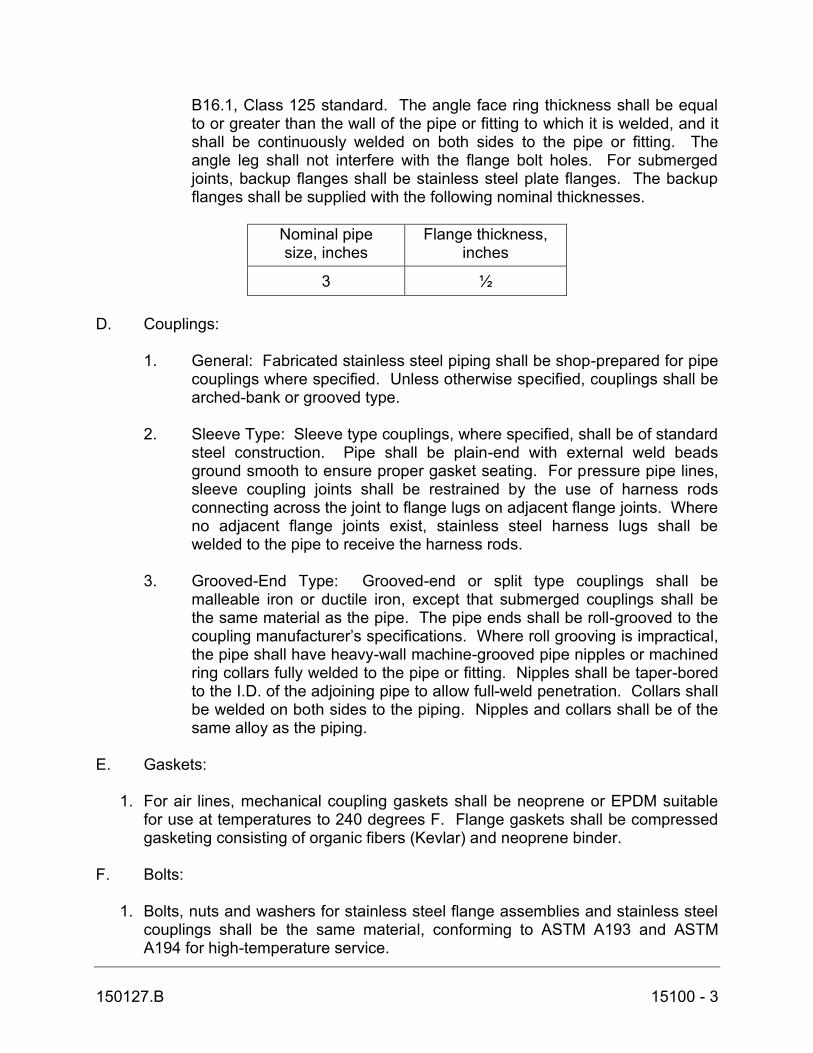
150127.B 15100 - 3
B16.1, Class 125 standard. The angle face ring thickness shall be equal to or greater than the wall of the pipe or fitting to which it is welded, and it shall be continuously welded on both sides to the pipe or fitting. The angle leg shall not interfere with the flange bolt holes. For submerged joints, backup flanges shall be stainless steel plate flanges. The backup flanges shall be supplied with the following nominal thicknesses.
Nominal pipe size, inches
Flange thickness, inches
3 ½ D. Couplings:
1. General: Fabricated stainless steel piping shall be shop-prepared for pipe couplings where specified. Unless otherwise specified, couplings shall be arched-bank or grooved type.
2. Sleeve Type: Sleeve type couplings, where specified, shall be of standard
steel construction. Pipe shall be plain-end with external weld beads ground smooth to ensure proper gasket seating. For pressure pipe lines, sleeve coupling joints shall be restrained by the use of harness rods connecting across the joint to flange lugs on adjacent flange joints. Where no adjacent flange joints exist, stainless steel harness lugs shall be welded to the pipe to receive the harness rods.
3. Grooved-End Type: Grooved-end or split type couplings shall be
malleable iron or ductile iron, except that submerged couplings shall be the same material as the pipe. The pipe ends shall be roll-grooved to the coupling manufacturer’s specifications. Where roll grooving is impractical, the pipe shall have heavy-wall machine-grooved pipe nipples or machined ring collars fully welded to the pipe or fitting. Nipples shall be taper-bored to the I.D. of the adjoining pipe to allow full-weld penetration. Collars shall be welded on both sides to the piping. Nipples and collars shall be of the same alloy as the piping.
E. Gaskets:
1. For air lines, mechanical coupling gaskets shall be neoprene or EPDM suitable for use at temperatures to 240 degrees F. Flange gaskets shall be compressed gasketing consisting of organic fibers (Kevlar) and neoprene binder.
F. Bolts:
1. Bolts, nuts and washers for stainless steel flange assemblies and stainless steel couplings shall be the same material, conforming to ASTM A193 and ASTM A194 for high-temperature service.
150127.B 15100 - 4
2.02 STAINLESS STEEL PIPE APPURTENANCES A. Grooved End Couplings
1. Grooved end flexible-type couplings shall be Gustin-Bacon 100, Victaulic Style 77, or equal. Grooved end rigid-type couplings shall be Gustin-Bacon 120 Rigi-Grip, Victaulic Style 07 Zero-Flex, or equal. Flexible-type couplings shall be used for all piping greater than 12 inches in diameter; for pipe 12 inches in diameter and less in rack-mounted tunnel piping applications; and for grooved joints adjacent to pump or blower suction and discharge where grooved couplings are used for noise and vibration control. All other applications for piping 12 inches in diameter and less shall utilize rigid-type couplings. Grooved end flanged coupling adapters shall be either Gustin-Bacon 154, Victaulic Style 741, or equal. Snap-joint grooved end couplings shall be Gustin-Bacon 115, Victaulic Style 78, or equal. Cut grooves are not permitted on fabricated or light wall pipe.
2. Unless otherwise specified, bolts and nuts shall comply with AWWA C606. Bolts for submerged service shall be Type 316 stainless steel in conformance with ASTM F593, marking F593F. Nuts for submerged service shall be made of copper-silicon alloy bronze conforming to ASTM B98, alloy C65100, designation H04 or alloy C65500, designation H04. Bolts and nuts for buried service shall be made of noncorrosive high-strength, low-alloy steel having the characteristics specified in ANSI/AWWA C111/A21, regardless of any other protective coating. Where washers are required, they shall be of the same material as the associated bolts.
3. Gaskets shall be as specified under paragraph 15100, 2.05. B. Butterfly Valves
1. Valves shall be rated at 175 psig and provide drip tight shutoff up to the full valve rating on dead-end or isolation service. Seat shall be mechanically held in place and shall be field replaceable. Valve ends shall be wafer type. Valve shall have seats that are bonded to a rigid reinforcing ring.
2. Valve shall have the following: stainless steel shaft meeting ASTM A582 Type 316; Cast iron disc meeting ASTM A126 Class B; neoprene or Buna-N seat sealing surface; cast iron body meeting ASTM A126 Class B; and disc edge made of nickel.
3. Valves shall have manual operators designed in accordance with AWWA C504 and shall have a disc position indicator designating the opened and closed position of the valve. Valves shall have latch lock levers and be capable of being locked in at least five intermediate positions between fully open and fully closed.
4. Valve shall be model BOS-US as manufactured by DeZurik, or equal.

150127.B 15100 - 5
2.03 DUCTILE IRON PIPE AND FITTINGS A. Pipe: 1. All wastewater process piping shall be ductile iron pipe and shall have
flanged ends of the sizes shown on the Contract Drawings, or as specified herein. The jointed sections of the piping shall be so placed as to allow maintenance and to permit units and equipment connected to the piping to be removed without disturbance to the main piping systems. All ductile iron pipe shall be cement lined (standard thickness) in accordance with ANSI/AWWA C104/A21.4.
2. All ductile iron pipe shall be manufactured in accordance with the standards of ANSI/AWWA C151/A21.51 and ANSI/AWWA C150/A21.50. Ductile iron pipe shall be not more than 20 feet in length.
3. All above ground ductile iron pipe shall be furnished with flanged joint end design conforming to ANSI/AWWA C115/A21.15 and ANSI B16.1, faced and drilled 125# standard.
5. The nominal thickness of all ductile iron pipe shall not be less than ANSI/AWWA C151/A21.51 Class 50 for mechanical joints and Class 53 flanged joints.
6. Ductile iron pipe/pipe system shall be furnished by Griffin Pipe, American Cast Iron Pipe Company, U.S. Pipe and Foundry, or equal.
B. Fittings: 1. All fittings and specials for ductile iron pipe shall be made of cast iron or
ductile in accordance with ANSI/AWWA C110/A21.10 and/or ANSI/AWWA C153/A21.53.
2. Fittings and specials for underground ductile iron pipe shall be provided with mechanical joint ends or push-on ends, furnished in accordance with ANSI/AWWA C111/A21.11, except where otherwise indicated on the drawings or required by the pipe, valves or other materials being placed or installed.
3. Fittings and specials for exposed ductile iron pipe shall be flanged in accordance with ANSI/AWWA C110/A21.10 and ANSI B16.1 faced and drilled 125# standard, or grooved in accordance with AWWA C606, except where otherwise indicated on the drawings or required by the pipe, valves or other materials being placed or installed.
4. Restrained Joints: Mechanical joint restraints shall be wedge type. Furnish Megalug as manufactured by EBAA Iron, Gripper Gland as manufactured by U.S. Pipe, or equal. Set screw retainer glands will not be permitted.
5. Flange Adapters: Flanges shall be drilled to meet ANSI B16.1 125# standard. Flange material shall be ductile iron meeting ASTM A536

150127.B 15100 - 6
Grade 65-45-12. The Gasket shall be EPDM suitable for wastewater. Set screws shall be AIAI 4140 Steel-tensile 190,000 psi minimum, heat traced to Rockwell C42-50 and zinc plated for corrosion resistance. Flange adapter shall be Uni-Flange Series 400 or equal.
C. Pipe Coatings: 1. The interior of all cement lined ductile iron pipe and fittings shall be sealed
with a bituminous seal coat per ANSI/AWWA C104/A21.4. 2. The exterior surfaces of all ductile iron pipe and fittings for interior
exposed installation shall be shop coated with a universal primer suitable for finish painting after installation in accordance with Section 09900.
2.04 VALVES A. General: 1. Provide valves of the same type and size range by same manufacturer;
suitable for the intended service. 2. Markings shall be factory cast on the bonnet or body of each valve
indicating manufacturer's name or mark, year of valve casting, size of valve, directional flow arrow and designation of working water pressure.
3. Valve pressure temperature ratings of not less than the design criteria applicable to system components.
4. Valves shall open to the left (counterclockwise). Valves shall be operated by nut, hand wheel, lever, floorstand, chainwheel or otherwise as indicated on the Drawings or specified herein. Operating nuts or wheels shall have cast thereon an arrow indicating the direction of opening.
5. Provide chain wheels and chains for operating overhead (5 feet or greater above finished floor) or inaccessible valves.
6. Valves buried (all) or below floor/floor level (when indicated on Contract Drawings) shall be provided with stainless steel extension stem operators. Operating nut shall terminate no more than 6 inches below surface. The unsupported length of extension stems shall not exceed 10 feet. Furnish valve position indicators and debris shield, as manufactured by Trumbull, for all buried or below floor valves.
7. Floor stand operators shall be standard pattern non-rising stem, indicating type and manufactured by Clow, or equal. Provide necessary accessories for mounting and proper operation of floor stand operators where indicated on contract drawings.
8. For wrench operated valves, provide at least one wrench for each type and size valve except where valves are in convenient groups; supply one wrench for each four valves.
9. Valve ends shall be as indicated on the Drawings or specified herein and unless indicated otherwise shall conform to the following:
a. Grooved: AWWA C 606.
150127.B 15100 - 7
b. Flanged: ANSI B16.1 & AWWA C110/A21.10 c. Mechanical: ANSI/AWWA C111/A21.11 10. Valve flanges shall conform to ANSI B16.10, 125# and 250# Class as
applicable. 11. Cast-iron valve material shall meet or exceed the requirements of ASTM
A-126, Class B. C. Swing Check Valves (Rubber Flapper): 1. Swing Check valves 2” in Diameter and Larger: a. Designed for a minimum working water pressure or 150 psi. b. Cast iron body, full opening swing check type with bolted cover and
316 stainless steel hardware. c. Rubber flapper shall be reinforced NBR. d. Acceptable Manufacturers: DeZurik-Apco Model CRF100 or
approved equal.
D. Gate Valves: 1. 2” and larger a. Gate valves shall be iron body, bronze mounted, resilient seated
wedge type in accordance with AWWA C509 and these specifications.
b. Valve bodies and bonnets shall be cast iron. Valve hand wheels, stuffing boxes and wedges shall be ductile iron, ASTM A536. The wedge shall be fully encapsulated with synthetic rubber for the resilient seat. The wedge shall be symmetrical and seal equally well with flow in either direction. There shall be no exposed metal seams, edges or screws within the waterway when the valve in the fully closed position. Tongue and groove guides shall be provided on the sides of the gate and in the body to keep the gate centered between the seats throughout its length of travel.
c. Valve stems shall be bronze in full compliance with Section 4.7 of AWWA C509. Design of the stuffing box shall permit repacking while valve is fully open and under line pressure.
d. Valve interior and exterior shall be fully epoxy coated in compliance with AWWA C550.
e. All gate valves shall be rated for 200 psi working pressure. f. Unless otherwise indicated or required, valves for above ground
ductile iron pipe shall have flanged ends in accordance with ANSI B16.1, Class 125. Provide square operating nut and extension stem.
g. Gate valves with extension stems shall be non-rising stem (NRS) type.
h. Acceptable Manufacturer: Mueller 2360 Series, American Flow Control Series 2500 NRS; or approved equal.
150127.B 15100 - 8
E. Plug Valves - 3" in Diameter and Larger: 1. General: a. Valves shall be of the non-lubricated, eccentric type with resilient
faced plugs and shall be furnished with end connections as shown on the Drawings. Flanged valves shall be faced and drilled in accordance with the ANSI B 16.1 Class 125/150 lb. standard.
b. All plug valves for the entire plant shall be furnished by one manufacturer.
c. The minimum port area thru the valve shall be at least 100% of the full pipe area.
d. Flanged Valves 6 inches and larger and all buried mechanical joint valves shall be gear operated to allow for proper plug orientation.
e. Valve bodies shall be of ASTM A-126 Class B cast iron in compliance with AWWA C507-73 Section 5.1. All exposed nuts, bolts, springs, washers, etc. shall be stainless steel or zinc plated.
f. Valve pressure ratings shall be as follows and shall be established by hydrostatic test as specified by ANSI B16.1.1967. Pressure ratings shall be 175 psi for valves through 12 inches. Valves shall be capable of providing drip-tight shut-off up to the full rating with pressure in either direction.
g. All plug valves shall be provided with a valve position indicator which can be read from the floor level.
h. Unless otherwise indicated or required, underground (buried) plug valves shall have mechanical joint ends or grooved ends. Provide stainless steel extension stem, valve box and cover for each valve. Operating nut shall be extended to within 6 inches of top of valve box. Underground valves shall be given a protective outside coating of coal-tar epoxy, minimum 75 percent solids by volume, to a dry film thickness of 8 mils minimum.
i. When grooved end valves are used for buried valves, a plain end/grooved end spool piece must be provided to transition from mechanical joint pipe to grooved end valve. Grooved couplings shall be furnished with 304 stainless steel nuts and bolts.
j. Plug valves shall be DeZurik, Pratt, or equal. 2. Plug: a. The plug shall be of one piece construction and shall be capable of
withstanding the full pressure rating of the valve in either direction without the use of structural ribs that extend beyond the profile of the plug.
b. The plug shall be covered with a resilient neoprene suitable for use in sewage, and no metal part of the plug shall be exposed to sewage.
150127.B 15100 - 9
3. Seats: a. Valves shall be furnished with corrosion resistant, non-ferrous
metal seats which comply with AWWA C507-73, Section 7, Paragraph 7.2.
b. Seats shall be raised so that the plug does not come in contact with the iron body of the valve when the plug is in the closed position.
4. Bearings: a. Valve plugs shall be furnished with replaceable, sleeve type 300
series stainless steel or bronze bearings on the upper and lower journals.
b. Bearings shall be designed not to exceed a stress of 1/5 of the compressive strength of the material used and the stress shall not exceed 2,000 psi.
5. Shaft Seals: a. The plug shaft seal shall utilize a stuffing box and split pull-down
packing gland, or other means. b. The plug shaft seal shall be adjustable and completely replaceable
without disturbing or removing the operator or actuator from the valve.
c. The plug shaft seal shall be capable of being replaced or repacked while under line pressure with the valve in the open position.
d. Any leakage thru the plug shaft seal shall be allowed to drain away from the valve and shall not be allowed to enter the operator.
6. Operators: a. Manually operated plug valves 6 inches and larger shall have
geared operators and shall be provided with hand wheels or chain wheels. All manually operated valves located higher than 5 feet above the floor, except those provided with extension rods for operating from above shall be chain operated, with the chain extending to within 5 feet of the floor. All hand wheel operated valves shall open with counterclockwise rotation of the wheel. For valves located in horizontal pipes, the valve and operator shall be arranged such that when the valve is open, the plug shall be located above the horizontal centerline of the pipe.
b. Plug valves shall be provided with operators as indicated in the Contract Drawings.
2.05 MISCELLANEOUS APPURTENANCES A. Shear Gates 1. Frame shall be of cast iron to receive the bolt on wedges and shall be of
the flanged type drilled for mounted to an ANSI 125# flange or mounting to a wall.
2. The seating surface shall be bronze machined to a smooth surface. The wedges shall be cast bronze and be securely attached to the frame

150127.B 15100 - 10
utilizing two stainless steel bolts per wedge and shall be adjustable to ensure proper closure.
3. A cast iron lifting lug shall be bolted to the cover in such a manner as to allow a swiveling action. The lug shall be made so that it accepts a pipe type lifting rod which is to be field cut to the desired length. Contractor shall provide supports for securing lifting rod to existing wall as necessary to match configuration of existing installation.
4. Shear gates shall be as manufactured by Waterman Industries, Inc. Model C-16 or approved equal.
PART 3 - EXECUTION 3.01 PREPARATION A. Field Measurement: 1. The Drawings are in general indicative of the work, with symbols and
notations for clarity. However, the drawings are not an exact representation of all conditions involved, therefore, layout piping to suit actual field measurements. No extra compensation will be made for work due to differences between indicated and actual dimensions.
2. Submit details of proposed departures necessitated by field conditions or other causes to the Engineer for approval.
3.02 INSTALLATION (PIPING) A. General: 1. Clean piping prior to installation and following installation to prepare for
painting. Keep open ends of piping and pipe attachment openings on equipment capped or plugged until actual connection.
2. Construct piping from full lengths of pipe using short sections only for runs of less than full pipe length. Make changes in direction of pipe runs with fittings only.
3. Cut pipe accurately to measurements established in the field and assemble in place without springing, forcing, excessive cutting or weakening of the structure.
B. Exposed Piping: 1. Run piping parallel or perpendicular to the lines of the structure. Keep
piping a sufficient distance from other work to permit clearance of not less than one inch between the piping or insulated piping and adjacent work. Install piping as close as possible to walls, overhead construction, columns, and similar to facilitate insulating work and removal of piping later.

150127.B 15100 - 11
2. Run piping to compensate for structural interferences, to preserve headroom, and not to interfere with openings, passageways and equipment.
3. Do not install piping with joints and fittings over motors, switchboards, panels, or similar electrical apparatus.
4. Install unions and flanges in accessible locations and where indicated or not, install union adjacent to all equipment and wherever removal of equipment for repair or replacement is required. Use dielectric unions at points of connection of copper tubing and piping to ferrous metal piping or equipment.
C. Pipe Joining: 1. General: Exercise care when making pipe joints and make joints in
accordance with the pipe material manufacturer's recommendations and the following requirements. In each instance of pipe joining, those portions of pipes involved must be absolutely clean just prior to assembly. If a joint is extremely difficult to assemble or sealing is not affected, disassemble the joint and correct the difficulty if possible. Remake the joint using new materials when necessary.
2. Grooved End Joints: Pipe ends shall be clean and free from indentations, projections and roll marks in the area from pipe end to groove for proper gasket sealing. The gasket style and elastomeric material (grade) shall be verified as suitable for the intended service as specified. Gaskets shall be molded and produced by the coupling manufacturer. See the latest copy of the Victaulic Field Assembly and installation instruction pocket handbook (l-300). All castings used for coupling housings, fittings, valve bodies, etc., shall be date stamped for quality assurance and traceability.
4. Flanged Joints: Make ductile iron and steel pipe joints faced true, fitted with gaskets, and drawn up square and tight to insure full pipe flow and satisfactory seal.
D. Plug Valves: All plug valves shall be installed so that the plug is in the upper quadrant of the valve body in the open position. The plug shall rotate downward to close. E. Stainless Steel Piping – Welding: 1. General: Piping with wall thickness up to 11 gage (0.120inch) shall be
welded with the TIG (GTAW) process. Concavity, undercut, cracks, or crevices shall not be allowed. Butt welds shall have full penetration to the interior surface, and inert gas shielding shall be provided to the interior and exterior of the joint. Excessive weld deposits, slag, spatter, and projections shall be removed by grinding. Welds on gasket surfaces shall be ground smooth.

150127.B 15100 - 12
2. Field Welding: Field Welding shall be minimized to the greatest extent possible by use of couplings and prefabrication of pipe systems at the factory. Pipe butt welds may be performed at the job site, providing the butt welds are performed only with an inert gas shielded process and that other applicable specified welding requirements are rigidly adhered to. Any field welding will require strict adherence to proper preparation, ideal weather conditions, defects found and properly repaired, grounded satisfactorily and thoroughly cleaned and inspected. All residue, oxide, and heat stain are to be removed from any type of field weld and the affected areas adjacent by the use of stainless steel wire brushes, following by cleaning with an agent such as Eutectic Company’s “Eucleen,” or equal, followed by complete removal of the agent.
3. Fabrication/Installation Requirements: The piping supplier during manufacturing, fabricating and handling stages, and the Contractor during handling and installation stages, shall use extreme care to avoid the contact of any ferrous materials with the stainless steel piping. All saws, drills, files, wire brushes, etc. shall be used for stainless steel piping only. Pipe storage and fabrication racks shall be nonferrous or stainless steel or rubber-lined. Nylon slings or straps shall be sued for handling stainless steel piping. Contact with ferrous items may cause rusting of iron particles embedded in the piping surface. All welded joints shall be treated with a pickling solution, brushed with stainless steel wire brushes and rinsed clean. If rusting of embedded iron occurs, the Contractor shall pickle the affected surface with Oakite Deoxidizer SS, or equal, scrub with stainless steel brushes, and rinse clean.
F. Cleaning (Existing 8-inch & 12-inch air supply headers and new piping):
1. Air system piping 6 inches in diameter and smaller shall be blown out, using air or the testing medium specified below. Piping larger than 6 inches shall be cleaned by having a swab or "pig" drawn through the separate reaches of pipe. After connection to the equipment, it shall then be blown out using the equipment. Upon completion of cleaning, the piping shall be drained and dried with an airstream.
G. Testing:
1. The Inspector or Engineer shall be notified in advance of all tests, and all tests shall be conducted to his entire satisfaction.
2. All stainless steel piping shall be tested with air at 3 psi and all joints and fittings shall be covered with soap solution to check for leakage.
3. All ductile iron piping shall be tested with water at 50 psi and shall retain this pressure over a period of 30 minutes without leakage
4. Leaks and defects shall result in the pipe being repaired, replaced or otherwise remedied by the Contractor at no expense to the Owner and to the complete satisfaction of the Engineer. Repair or replacement of pipe

150127.B 15100 - 13
shall be accomplished when leaks become apparent and shall be completed within one month after detection of leak, but prior to Owner’s final acceptance of the project.
3.03 DEFECTS TO BE MADE GOOD A. If, at any time before the expiration of the guarantee period under this contract, any broken pipe, humps, sags, settlements, bellies, or any other defects are found in any of the lines or in any of the appurtenances, the Contractor shall cause the same to be removed and replaced by proper material and workmanship, without extra compensation for the labor and material required, even though such injury or damage may have been due to any act, default, or negligence on the part of the Contractor. All materials shall be carefully examined by the Contractor for defects prior to installation, and any found defective shall be rejected for use.
* END OF SECTION *

This Page Intentionally Left Blank