note and correspondence -...
TRANSCRIPT

NOTE AND CORRESPONDENCE
TAO, Vol 志 , No.1, 109-119, M 缸ch 1994
Ocean Bottom Seismograph:Instrumentation and Experimental Technique
1.2ALLEN T. CH 凹 / YOSIO NAKAMURA"'" and lI-WEI Wu
(Manu 甜 ipt re 個 iv 回 5 January 1994. in final form 22 March 1994)
ABSTRACT
A set of Ocean Bottom Seismographs (OBS) has been constructed re.cenUy at the National Taiwan Ocean University (NTOU) for offshore seismicsurveys and earthquake observations. The instrument is identical in designto the recently upgraded Texas OBS. It is controlled by an 80C88 micropro-C自 sor. Signals from up to four channels of sensors are recorded digitally oneither a cartridge tape or a disk. It was successfully field tested during R/VOcean Researcher I cruise No. 277 in 1991, and has been in use in subsequentcruises.
(Key words: Instrumentation, Offshore measurement, Refraction)
1. INTRODUCTION
R目 ently, we built a set of three ocean bottom seismographs (OBSs) at the NationalT 剖W血 Oce 祖 University. They were successfully tested off southwestern Taiwan duringRjV Ocean Researcher I crui 田 No. 277 in 1991, and have been US 吋 in subsequentcruises Nos. 282 in 1991, 312 in 1992, 祖d 347 in 1993. The instrument can be deployedat depths of up to 60 ∞ meters. Although this was not the fir 到 time an OBS was used nearT 副W祖 (e.g., Hagan ef al., 1988), cruise No. 277 marked the fil'st Dee 晶 ion in which 祖 OBSbuilt and operated by a Chinese institution was used.
、四Ie instrument was built according to 血.e specifications of 出e recently-upgraded Texas
OBS developed by the Institute for Geophysics of the University of Texas at Austin (Naka-mura 血dO 缸many, 1991). It is the latest version of a long series of low-cost, small,easy-to-deploy-and-recover Texas OBS 泡 , starting from the earliest single-channel 血 alog in-stroment (Latham et al., 1978) and developed through the earlier digital units (Nakamura et叫 . 1987). For comparison of various OBS 法 , 也e reader may refer to a report by Sutton et
1 Institute of 0 個問 ography, National Taiwan Ocean University, Keelung, Taiwan, R.O.C.2 Institute for Geophysics, University of Texas at Austin, Austin, Texas 78759, U.S.A.
109

110 TAO, , 句>1.5, No.1, March 1994
aI. (1980) and a recent compilation by Trehu (1992). According 扭曲 is latter report, whichwas based on a survey conducted through the international marine seismological community,there were a total of 232 OBS's in the world, including three units from NTOU-R.O.C. TheTexas OBS's have been extensively used in studies of deep crustal structures in the MiddleAmerica Trench (Ibrahim et al.,1979) 組d in the Gulf of Mexico (e 息 , Ebeniro et 叫 , 1986,
1988), and in studies of micro-earthquakes in the Southwest Pacific (pontoise et al., 1979;Ibrahim et al., 1980; Chen et aL, 1981; Coudert et al., 1981; Frohlich et al., 1990) 組dinthe Aleutian Trench (Frohlich et aI., 1982). In this paper, we briefly describe the in 甜凹nentand 也e operational procedures for seismic refraction surveys. The use of these instrumentsh 個缸ray for offshore earthquake observations is planned for the near future.
2. SYSTEM DESCRIPTION
τ'he system consists of several interacting units, or modules, as shown in Figure 1 anddescribed below.
Recovery AidsFlagsRadio Beacons
Glass Sphere
C-44 Bus
Input
Shot Table Input
Release ModuleReal-Time Clock-
ReleaseBackup Clock-
Release
Turn onrol! TapeLogic/Molar Power
Steel Anchor Frame
Fig. 1. The OBS system block diagram.
2.1 Sensor Unit
The instrument accepts up to four channels of sensor inputs, which nQnnally consistof three orthogonal geophones and an optional hydrophone. 四lfee Mark Pr 吋ucts L-15B4.5-Hz geophones, two horizontals and a vertical, are mounted on gimbals to maintain alevel position even when the instrument housing is tilted by up to 25 degrees on the oceanH∞r. 百le gimbal mechanism is damped wi 血 high-viscosity silicon oil to maintain its levelposlUon.

Chen et al. 111
2.2 Signal Conditioning and Temporary Storage Units
Signals from the sensors are 缸nplified and low�pass filtered to avoid aliasing. A 出ree-stage 伊in-ranging arnpli 且er and a 14-bit analog- 阻 -digital convert 叮 (QADC-3 made by QSI)convert the filtered analog signal to a digital signal, achieving a .total dynamic range of 126dB. 四Ie maximum sample'rate is 1000 samples per second per channel. 官Ie digitized data aretemporarily stored in a random-access memo 可 (RAM) of 512K byte capacity on a memo 可bo 前d (RAM-2M made by 臼1晶。 -2.3 Recording Unit
The acquir 吋 data are 虹ansferred from 曲e temporary memo 可 to a more pe 口nanent
digital-recording device through a SCSI interface at a given interval or when the temporarymemo 可 is filled. Although practically any SCSI storage device will serve for the permanentstorage of data, we used a Tandberg TDC-36 ∞ cartridge tape drive on each of our first uni 阻 ,which gave a maximum of 155 M bytes of storage capacity on a 6O0-ft cartridge tape. Thiscapacity has since been upgraded to 525 M bytes using a lOoo-ft cartridge tape on a TandbergTDC-3820 tape drive. 四Ie system is also capable of recording the data on a hard disk, e.g.,Conner 3200 or Toshiba MK2224FB disk drive, each of which has 203 M byte capacity. Thepower to the recording device is controlled by the CPU through a pair of relays.
2.4 Control Unit
咽Ie system is controlled by an 80C88 micropr ∞essor on a CPU-8088 board manufac-tured by 臼lset. 甘lis bo 缸d also contains a small RAM, a programmable memo 可 (EPROM),in which the control software is stored, serial and parallel ports, and a crystal-controlled real-time clock. 百Ie processor controls the entire data-acquisition sequence 晶 well as the releaseof the instrument from the ocean floor following a pre-set schedule. Optionally, 出e pr' 田 ess-ing software may contain an event-detection algorithm that allows detection of earthquakeevents based on a long-term-short-term signal-level comp 訂1son.
2.5 Release Unit
Two independent release functions are employed to assure release of the instrumentfrom the anchor frame (see below) even when one fails to function properly. The main CPUcontrols one of them and issues a release command when the time for release as given in thepre-set schedule is reached. A backup clock, a pre 阻 t timer, also issues a release commandindependently when the preset time is up. Each release command turns on a separate relayto apply a current through a stainless steel wire (release wire), which then dissolves itself atsome water-exposed sections to relea 田 the instrument housing (see below) from the anchorframe.
2.6 Instrument Housing (pressure vessel)
世Ie whole electronic package is housed in a glass sphere of 43 cm (17 inch) diameter,which acts as a prl 自sure vessel, with the gimbaled geophone package firmly set at the insidebottom of 血e sph 叮e. The sphere is put into a hemispherical plastic pro 能ctive 'hat' and血en is fastened to a steel anchor frame with three pieces of elastic (bungee) cord tied to 血c

112 TAD, , 句1.5, No.1, March 1994
flags
sleet anchor frame
Fig. 2. 四le OBS sphe 時 is �晶 ten 吋 to the steel anchor franle wi 由 elastic cords.The recove 可副血 , including two radio transmitters and flags, are on topof 由.e OBS while a strobe light is installed inside the sphere (not shown).When the relea 品 wire is dissolved, the OBS is released from the 祖chorframe 祖d ascends to the surface of the water.
甘i扭扭 lar release wire mentioned above (Figure 2) for deployment. If a hydrophone is u 時d,it is attached to 血e outside of the sphere wi 曲 a water-tight cable conn 叫ion 血rough one of血.e pene 虹ators through the sphere.
2.7 Communication Connections
A specially designed electronic-switching circuitry, the 'switch box' (Figure 3), servesto establish three-way communication anlong the OBS, a standard clock, and a personalcomputer (PC). We use an Omega navigation-signal receiver 甜 the standard clock. A positionon the switch allows a two-way communication between the OBS and the PC. 前lis switchposition is used to start up the OBS, 個 set the internal real-time clock of the OBS, to performvarious test functio 肘 , to download a data-acquisition schedule, and to monitor the OBS whileit goes through the p 時間 t schedule. Another position allows two�\Vay communication between血e PC and the standard clock 個 set 血e latter for proper ou 甲ut format. Still another positiona副alln 叫』冊ws OBS-clock- 早C three-way communication, providing a means for accurate calibration
C'l the internal clock of the OBS against the standard clock.
2.8 Recovery Aids
臼le or two submersible radio transmitters (beacons) are attached to the sphere to 甘ans-mit radio signals. A pressure-sensitive switch turns on each transmitter as soon as the releasedinstrument reaches the surface. A direction finder is used to locate the instrument if it is out

113Chen et ai.
CJJ口一MACINTOSH
Fig. 3. The switch box serves as a linkage among OBS. PC and standard clock.
of sight. A strobe light, mounted inside the sphere, flashes to reveal the instrument at night.A fluorescent orange flag, attached to the transmitter antenna, serves as an additional aid fordaylight recove 可 ,
2.9 Power Supply
Independent 扭扭 of lithium batteries provide power for 伽 CPU/pre-amplifier -filter/ADC/RAM, 也e tape drive, the main release, the strobe light, and the power-switching relays.τhe required total number of size-D bane 可 cells, in addition to two smaller cells used for therelays, depends primarily on 血.e duration of data acquisition, and generally ranges from 19 to37. When fully loaded, the system can record data continuously for about a week, al 血oughit can stay dormant for several months. The submersible transmitters are each powered byfour size-C alkaline batteries.
3. EXPERIMENTAL PROCEDURES
We describe below the basic steps in conducting a refraction survey using these instru-ments. Details of these procedures 紅'e given in a separate instruction write-up we preparedfor the operators.
3.1 Pre-deployment Operations
Before each OBS deployment, a thorough check out of the instrument is performed tomake certain 曲 at all connections are properly made. We also fill out a check list, the pu 中O臨of which is to maintain proper records (e.g., component serial numbers) and to ascertaincorrect voltage levels at various key test points. We also record low-frequency squ 訂e waves,which provide calibration of the instrument. 明1e shape 個d size of squ 釘e waves recordedand played back in time domain are diagnostic of any malfunction of the signal channel.
114 TAG, , 句1.5, No.1, March 1994
Fourier transfonn of the s旬 -function response multiplied by frequency will give the overallfrequency respon 峙。f the signal channel.
A schedule table for activating, deactivating and releasing the OBS is prepared on aPC. This table al曲 includes all necessary p 缸缸neters for data acquisition, such 祖 number ofchannels and sampling interval.
When everything is ready, we turn on the power to 血e CPU, 品 t and start the internalreal-t 加e clock in synchronization with the standard clock, download the schedule table, andput 血e CPU into the sleep mode to con 配rve power while it is idle. The system consumesabout 3 m W of power in 血 is mode. It wakes up momentarily eve 可 minute to output a timecharacter string through a serial port, which may be used to calibrate the internal real-timeclock against the standard clock.
After the backup timer is set, the entire electronic package is installed inside the glass
叩here 個d sealed. Communication from here on, including clock calibration, 扭曲rough a晶 t of electrical feed-throughs (penetrators) through the sphere wall.
3.2 Deployment and Data Acquisition
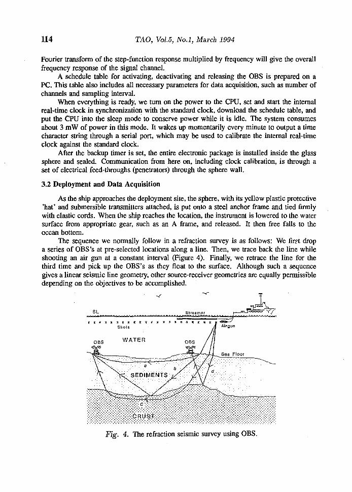
As the ship approaches the deployment site, the sphere, with its yellow plastic protective'hat' and submersible transmitters attached, is put onto a steel anchor frame and tied finnlyWI 血 elastic cords. When the ship reaches the location, the i恤ns風tn祖lsurface from a叩ppro 呻priat 臼eg酹e 缸, such a剖s 叩 A frame, and released. It then free falls to 由C
ocean bottom.The sequence we nonnally follow in a refraction survey is as follows: We 且rf't drop
a 田ries of OBS's at pre-s 巳lected locations along a line. 白1間 , we trace back the line whileshooting an air gun at a constant interval (Figure 4). Finally, we retrace the line for thethird time and pick up 血 e OBS's 扭曲ey float to the surface. Although such a 臨quencegives a linear seismic line geometry, other source-receiver geometries are equally pennissibledepending on the obj 也 tives to be accomplished.
SL Streamer � ι書賀喜賀嵩萬寶寶養費菁簣 , 賢萬寶安曼寶善著養著三E 三7
A" Airgun
吋'
『干,
WATER
Fig. 4. 四Ie refraction seismic survey using OBS.

Chen et al. 115
It is important 血at each shot t加 e be accurately recorded and referenced to the samestandard cl 凹k against which each OBS's internal clock is calibrated. We u 臨 specially builtcircuitry to generate a pulse from the shot-break signal supplied by the shot 甜quencer. Thepulse 扭曲.en sent to 血.e stand 紅d clock to request the current time, which is received by aPC and recorded.
3.3 Post�recovery Operation
Immediately following the recovery of each OBS, its internal clock is re-calibratedagainst the standard clock, and the content of the error log, which is kept 扭曲.e instrument's
memo 旬 , is displayed to reveal if there has been any problem. We also play back selectedportions of 血e recorded data to 品certain 血 at exp 自 ted data are properly recorded. If anyproblem is found, it must be corrected before the unit is re-deployed.
Before we re-deploy the instrument, we replace battery packs, if necessary, and go血rough a 血orough check-out as before. Mter restarting the instrument, we download a newschedule and follow the Donnal proced 叮es as described above. The tum-aroWld time isusually less 血 an two hours for each OBS.
4. TEST RESULTS
We conducted the first OBS field test off southwestern Taiwan during the RjV OceanResearcher I cruise No. 277 in 1991. We re ∞ rded 由ree components of seismic data at 4-mssampling intervals while shooting a small air-gun array of total available volume of to.2 1.
(620 in3) at 30 sec intervals while maintaining a constant cruising speed of 5.1 knots. Therecord 田ctions in Fi 扭扭 5 have been generated by stacking 甘aces into unifonnly spaced offsetbins, band-pass filtering the traces, and 吋Uusting 由e gain. The acquired data clearly showseismic arrivals of excellent quali 句 ; we can easily pick up some first arrivals even though血e source energy was small and multiples are 叫 so present. 百le most impressive featuresinclude the big offset of arrivals near 15 km, which may imply a structural discontinuity, andthe arrivals between distances of 25 個d 30 km, which represent signals from d臼p refraction.
百le OBS program at the National Taiwan Ocean University was started about t趾eeye 缸s ago. Our initial objective w 晶 to build up a capability to conduct research using 由isnew tool in studies of deep crustal structures and seismic activities in the offshore region ofTaiwan. To date, we have acquired data of reasonably good qu�lity eve 可 year since using血e 峙。BS's we built and operated. These data sets mark an important step towards a newresearch te 叮ito 可 in our studies of velocity structure and e 訂出 quake activities in offshoreregIOns.
Acknowledgments This work was supported by National Taiwan Ocean University, Na-tional Science Council grants NSC80-0202-MO19-01 and NSC80-0204-MO19- 肘 , and Min-is 呵。 f Education Tai(80) Wen17717.

116 TAO, Vol. 5, No.1, March 1994
2
VERTICAL
3
5
6
kmRJMhM3
4..
如立,-nMF
d.-
aae-FE--d
民
AVta
4..
3
4
5
(oom)
可通-h
16
Fig. 5. 四Ie raw DBS record sections of Line-277 for bo 血 vertical (a), 組d hori-zontal 駒 , c) components. The DBS is located at the far left of the profile.Water wave and 直 rst refracted arrivals can be easily picked. Noted thelarge offset of arrivals near 15 km and arrivals from deep refraction after25 km in vertical component (a).

117Chen et 叫 ,
RADIAL
km255 10 15
1
11
{uom)
可\
4.FH
(Fig. 5. Continued.)

118 TAD, Vo1.5, No.1, March 1994
TRANSVERSE
Munnvj
3RU
、
1
而4
nuaEE
呵,‘
但u,言,
向U
主
RU
3
4
6
55
7
8
7
9
10
14
11
12
白5
13
{OOω
)
才可-H
(Fig. 5. Continued.)

Chen et al. 119
REFERENCES
Ch 凹 , A. T. 吋巳 FroWich, 祖.d G. La 曲帥 , 1981: Seismicity of the forearc marginal wedge(accretionary prism). J. Geophys. Res., 87, 3679-3690.
Coude: 此 , E., B. L. Isacks, M. B 缸扭曲函 , R. Louat, R. Cardwell, A. Chen, 1. Doubois, G.La! 血缸n, and B. Pontoi 峙 , 1981: Spatial distribution and mechanisms of ear 血.quakes 扭曲esouthern New Hebrides arc from a temporary land-OBS seismic network and worldwideobserv 叫 ions. J. Geophy ﹒ Res., 86, 5905-5925.
Ebe 世間 , J. 缸 , W. P. O'Brien, and F. J. Shaub, 1986: Crustal s 甘uct 山e of the south Roridaplatform, eastern Gulf of Mexico: 曲目ean-bottom seismograph refraction study. Mar.Geophy. Res., 8, 363-382.
Ebeniro, 1. 0., y: Nak 剖nura, D. S. Sawyer, and W. P. O'Bri 冊 , 1988: Sedimentary andcrustal s 甘ucture of the northwestern Gulf of Mexico. J. Geophy. Res., 93, 9075-9092.
Frohlich, C., S. Billingt 咽 , E. R. Engdahl, and S. Mal 曲。宜� 1982: Detection and locationof earthquakes in the central Aleutian subduction zone using land and ocean bottomseismograph stations. J. Geophy. Res., 87, 6853-6864.
Frohlich, 巴 , R. Louat, 祖d Y. Nak 缸nura, 1990: Earthquake activity in the southern Vanuatu缸'c recorded by the Texas digital OBS. Mar. Geophy. Res., 12,253-267.
Hag 間 , R. A, F. K. Duennebier, and V. Hsu, 1988: A seismic refraction study of the crustalS 甘ucture 扭曲e active seismic zone east of T: 剖W間 . J. Geophy. Res., 93, 4785-4796.
品,rahim, A. K 吋 G. Lath 紅n, and J. Ladd, 1979: Seismic refraction and reflection measurements面 the middle America Trench offshore Guatemala. J. Geophy. Res., 酬 , 5643-5649.
Thr 曲恤 , A., B. Pontoise, G. La 血 am, M. Lar 曲 , T. Chen, B. Isacks, J. Recy, and R. Louat,1980: S 甘ucture of the New Hebrides arc-trench system. J. Geophy. Res., 85, 253-266.
La 血缸丸丘 , P. Donoho, K. Gri 扭曲s, A Roberts, and A K. Ibrahim, 1978: The Texas 田 ean-bottom seismograph. Proc. 10th Offshore Technology Conference, paper OTC3223,1467-1476, May 1978, Hostom, Texas.
Nakamura. Y., P. L. Donoho, P. H. Roper, and P. M. McPherson, 1987: Large-offset seis-mic surveying using ocean-bottom seismographs 血d air guns: Instrumentation and fieldtechniques. Geophysics, 缸 , 1601-1611.
N akamu 間 , Y., and 1. G 訂many, 1991: Development of upgraded ocean-bottom seismograph.University of Texas Institute for Geophysics Tech. Rept. No. Ill,45pp.
Pontoi 峙 , 且 , G. 扭曲徊 , J. Daniel, J. Dupont, and A. Ibrahim, 1979: Seismic refractionstudies in the New Hebrides and Tonga area, Proe. Symposium on Petroleum Poten-tial in Island Arcs, Small Ocean Basins, Submerged Margins and Related Area.