(notched tensile test of a compact …bj/meg_795_e_methods/pdf_files/anand ct...(notched tensile...
TRANSCRIPT

(NOTCHED TENSILE TEST III)(NOTCHED TENSILE TEST OF A COMPACT TENSION SPECIMEN)
Anand Venkatesh
MEG 795 Special Topics: Energy Methods II
COMPUTATIONAL SIMULATION OF TENSILE TESTING USING SPECIMENS OF DIFFERENT
CONFIGURATIONS

OBJECTIVE
• The primary goal of this study is to evaluate the mechanical properties of a Compact Tension (CT) specimen by developing a computational model.
• To study the effect of different mesh configurations on the refinement of the generated data.
• To compare the results obtained with the current computation with earlier computation results.

Material Properties to be Evaluated
• Maximum Stress at an initial velocity of 50 inch/sec
• Resultant Displacement
• Effective Plastic Strain

Modeling• The CT specimen was modeled using Solid Works
• ASTM standard E 399 CT dimensions were observed for modeling
• The width (B) of the specimen was maintained at 1 inch and height (H) was 2.40 inches (1.25W) and distance from the crack tip to the to the centre of the hole is 0.55 inches

SolidWorks Model
EP-823 COMPACT TENSION (CT) SPECIMEN

Half-Section Chosen For Analysis

Material Input for the Specimen
Density: 0.283599 lb/in3
Yield Stress:110 *103 Psi
E: 3 *107 Psi
Non-Linear Isotropic3-D Solid 164EP-823
Material PropertiesMaterial ModelElement TypeMaterial

Meshing Technique
• The model was imported in ANSYS to perform different meshing schemes.
• The half-sectioned model is meshed as solid elements
• Two meshing schemes were used as follows:���� Mesh I���� Mesh II (Refined Mesh)
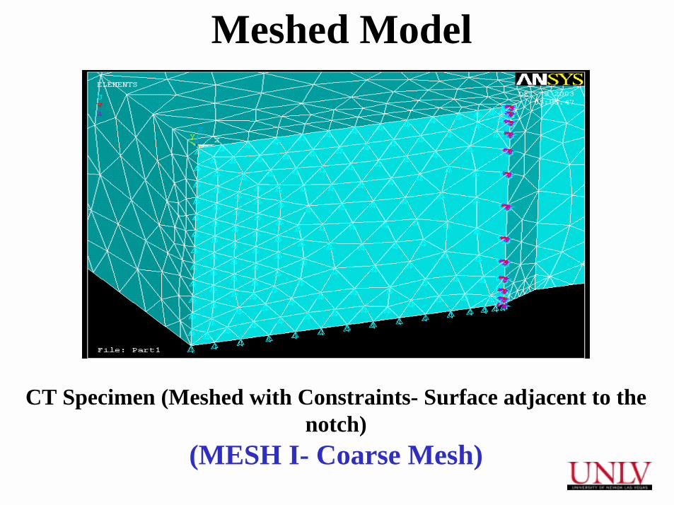
Meshed Model
CT Specimen (Meshed with Constraints- Surface adjacent to the notch)
(MESH I- Coarse Mesh)

CT Specimen (Meshed with Constraints- Surface adjacent to the notch)
(MESH II – Finer Mesh)

Results from LS DYNA Analysis
���� PARAMETERS TO BE EVALUATED
• Maximum Stress at an initial velocity of 50 inch/sec
���� CONTOURS PLOTTED
• Maximum Stress Contour• Effective Stress Vs. Time• Resultant Displacement Vs. Time• Effective Plastic Strain Vs. Time

Maximum Stress Contour (Mesh I)Max. Stress = 110 ksi

Maximum Stress Contour in the notched region from LS DYNA

Effective Stress vs. Time

Resultant Displacement vs. Time

Effective Plastic Strain vs. Time

Maximum Stress Contour (Mesh II)Max. Stress = 110 ksi

Maximum Stress Contour in the notched region from LS DYNA

Effective Stress vs. Time

Resultant Displacement vs. Time

Effective Plastic Strain vs. Time

Computational Results
2742692 II
851662I
CPU TimeNo. of Nodes
EP-823 COMPACT TENSION SPECIMENMesh Configuratio
n
Comparison of No. of nodes and CPU time

110.0 110.0COMPACTTENSILE
EP-823
MESH SCHEME II (ksi)MESH SCHEME I (ksi)CONFIGURATIONMATERIAL
Computational values of stress from LS DYNA
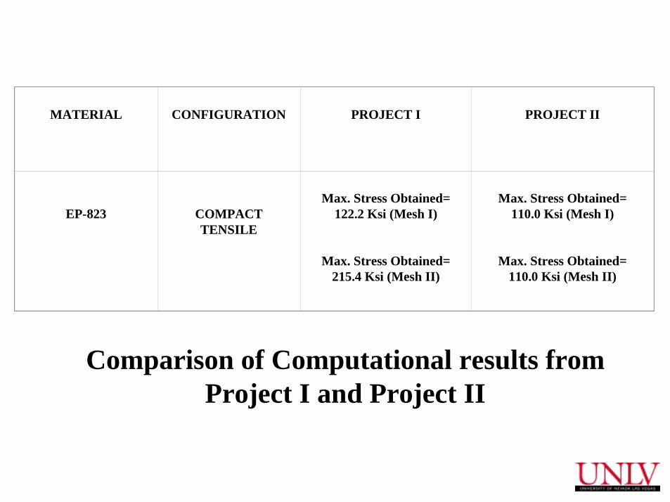
MATERIAL CONFIGURATION PROJECT I PROJECT II
EP-823 COMPACT TENSILE
Max. Stress Obtained= 122.2 Ksi (Mesh I)
Max. Stress Obtained= 215.4 Ksi (Mesh II)
Max. Stress Obtained= 110.0 Ksi (Mesh I)
Max. Stress Obtained= 110.0 Ksi (Mesh II)
Comparison of Computational results from Project I and Project II

Conclusions• The compact tension specimen was studied under
different mesh configurations for the evaluation of various parameters resulting from an application of a chosen initial velocity.
• Comparitive analysis was performed with the results of computation from the two projects .
• Contours were plotted for Effective Stress , Resultant Displacement and Effective Strain.