northeast monitoring, inc. dr180+ digital...
TRANSCRIPT

NorthEast Monitoring, Inc.DR180+ Digital Recorder
Operator’s Manual
Copyright 2006 - NorthEast Monitoring, Inc.May 2006
Part number: NEMM001 revision I


Table of contents
Physical Specifications 2Electrical Specifications 2Power Supply 2Patient Leads 2Operator Interface 2Storage Capacity 2Hooking up the Patient 3Preparing the Recorder 5How Patients use the Event Button 8Erasing a Compact Flashcard 9Other Recorder Settings 10Recording Continuous 12-lead 13Memory Requirements for 12-Lead Recordings 16Processing Data Collected in Continuous 12-lead Modes 17Error Messages 19Appendix A: Maintenance and Care of the DR180+ Digital Recorder 20Appendix B: Batteries for the DR180+ Digital Recorder 21Appendix C: Pacemaker Detection with the DR180+ Digital Recorder 23Appendix D: DR 180+ Accessories 24


HOW TO USE THE DR180+ DIGITAL HOLTER RECORDER
Guide to NorthEast M
WARNING: Federal law restricts this device to sale by or on the order of a physician.
The NorthEast Monitoring, Inc. DR180+ Digital Recorder is a Holter monitor designed to facilitate the ambulatory cardiac monitoring, on order of a physician, of those patients who may benefit from such mon-itoring, including but not limited to those with complaints of palpita-tions, syncope, chest pains, shortness of breath, or those who need to be monitored to judge their current cardiac function, such as patients who have recently received pacemakers. Only a trained Holter technician should do patient hookups.
The data obtained by monitoring is not analyzed at the time of record-ing. After the recording is complete, the data must later be downloaded to a compatible NorthEast Monitoring, Inc. Holter analysis system to be analyzed.
Note: The DR180+ is not intended to replace real-time telemetry monitoring for patients suspected of having life-threatening arrhythmias.
NorthEast Monitoring, Inc. is an FDA Registered Facility (1224919) that follows all FDA CGMP Manufacturing Practices. The DR180+ Digital Recorder has FDA 510K Approved Product Certification (K001288 and K004007) and meets the AAMI EC-11/EC-38 standard for frequency response.
onitoring, Inc.’s DR180+ Digital Holter Recorder
2
Physical Specifications
The DR180+ Digital Recorder meets the fol-lowing physical specifications:
• 12.5 cm (length) x 7.0 cm (width) x 2.5 cm (depth)
• 4-7/8 inches (length) x 2-3/4 inches (width) x 1 inch (depth)
• Weight: 142 g (5.0 oz) without batteries; 200 g (6.9 oz) with batteries
Electrical Specifications• Recording bandwidth: 0.05 to 70 hertz in 3-
channel mode• Prefilter sampling rate: 360 samples/second
in 3-channel mode• Data stored: 180 samples/second. In high
resolution mode, signal processing ensures capture of peaks of narrow QRS com-plexes.
• Pacemaker sensitivity: 2 millivolts• Pacemaker pulse duration: 150 to 2,000
microseconds• The degree of protection against electric
shock is Type BF• The recorder has not been tested for use in
the presence of a Flammable Anaesthetic mixture and, therefore, is not suitable for use in the presence of a Flammable Anaes-thetic mixture with air or with oxygen or nitrous oxide
Power SupplyThe DR180+ is powered by two 1.5 volt AA alkaline batteries (MN1500 or the equivalent), two AA rechargeable NiMH (nickel metal hydride) batteries, or two AA Eveready Lith-ium L91 batteries.
Patient LeadsThe DR180+ is compatible with standard sil-ver/silver-chloride ECG electrodes.The
DR180+ uses patient cables with either seven leads or five leads for a 3-channel Holter recording, or ten leads for a 3-channel Holter plus 12-lead data. The cable connects to the recorder via a 15-pin female connector on the recorder.
An oximetry lead set with an oximetry sensor replacing the channel 3 leads is also available. The oximetry lead set consists of five leads for a 2-channel Holter recording and a detachable Nonin Medical lead with a pulse oximetry sen-sor. The cable connects to the recorder via a 15-pin female connector on the recorder.
Note: Please be sure to not pull on or stretch the patient cables when you clean them or attach them to the recorder or the patient. This can cause premature failure of the cable.
Operator InterfaceThe DR180+ has a 13-key keypad on the face of the recorder around a liquid crystal display (LCD). Use the keypad to interact with and program the recorder. The function of each key on the keypad changes depending on the dis-play.
Storage CapacityThe patient’s Holter data is stored on a remov-able compact flashcard. To store 24 hours at either normal or high resolution, the minimum capacity of the compact flashcard should be 32 megabytes. Although 48 hours of 3-channel Holter signal might fit in 32 megabytes, we recommend that you use 64-megabyte flash-cards instead. Compact flashcards of up to 512 megabytes can be used.
For details about flashcard capacity for record-ing 12-lead data, see the tables on page 16.
Guide to NorthEast Monitoring’s DR180+ Digital Holter Recorder

Guide
Hooking up the Patient
cement
ne
line
Hooking up the PatientThe most important element in Holter monitor-ing is recording a clean long-term ECG signal. Because a clean signal is directly dependent on the hookup procedure, great care should be taken when hooking up the patient. Poor hookup causes poor signal quality and artifact.
To ensure proper hookup, follow these steps:
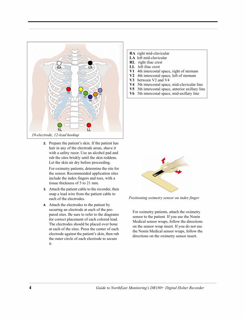
1. Using either the 5-electrode (3-channel) or the 7-electrode (3-channel) diagram shown below or the 10-electrode (3-channel Holter, 12-lead) diagram on the following page, identify sites for the electrodes. For oximetry patients, use only channels 1 and 2 on the 7-electrode hookup; two channels of Holter data will be recorded, and the oximetry lead will use channel 3.
7-electrode pla
Channel 1:
Channel 2:
Channel 3:
Ground:
- White right manubrium + Red 5th rib, left anterior axillary line
+ Brown 2 cm. right of xiphoid process
Channel 1:+ Brown 5th rib, left anterior axillary li
Green centered over rib
5-electrode placement
- Red centered on manubriumChannel 2:+ Black 5th rib, left of mid-clavicular - Red
Channel 3:+ Black- White right manubrium
Ground:Green centered over rib
+ Orange 5th rib, left of mid-clavicular line
- Black left manubrium
- Blue centered on manubrium
to NorthEast Monitoring, Inc.’s DR180+ Digital Holter Recorder 3
4
10-el
2. Prepare the patient’s skin. If the patient has hair in any of the electrode areas, shave it with a safety razor. Use an alcohol pad and rub the sites briskly until the skin reddens. Let the skin air dry before proceeding.For oximetry patients, determine the site for the sensor. Recommended application sites include the index fingers and toes, with a tissue thickness of 5 to 21 mm.
3. Attach the patient cable to the recorder, then snap a lead wire from the patient cable to each of the electrodes.
4. Attach the electrodes to the patient by securing an electrode at each of the pre-pared sites. Be sure to refer to the diagrams for correct placement of each colored lead. The electrodes should be placed over bone at each of the sites. Press the center of each electrode against the patient’s skin, then rub the outer circle of each electrode to secure it.
For oximetry patients, attach the oximetry sensor to the patient. If you use the Nonin Medical sensor wraps, follow the directions on the sensor wrap insert. If you do not use the Nonin Medical sensor wraps, follow the directions on the oximetry sensor insert.
Positioning oximetry sensor on index finger
ectrode, 12-lead hookup
RA right mid-clavicularLA left mid-clavicularRL right iliac crestLL left iliac crestV1 4th intercostal space, right of sternumV2 4th intercostal space, left of sternumV3 between V2 and V4V4 5th intercostal space, mid-clavicular lineV5 5th intercostal space, anterior axillary lineV6 5th intercostal space, mid-axillary line
Guide to NorthEast Monitoring’s DR180+ Digital Holter Recorder

Guide
Preparing the Recorder
5. If you use lead lock or clip lock elec-trodes, be sure to use the lock or clip to relieve stress on each lead wire; refer to the dia-gram at right for proper use. Otherwise, tape each lead wire into a stress loop (see the diagram below) to help prevent move-ment of the electrode.
Preparing the RecorderAfter connecting the patient to the recorder, follow these steps to start the recording:
1. Remove the door from the battery compart-ment of the DR180+, then insert a compact flashcard into the slot inside the compart-ment. Hold the flashcard by the edge with the ridge and orient it so that the opposite edge (with the connector) slides in first. Looking at the bottom of the recorder, you should see the bottom of the flashcard; if the flashcard was supplied by NorthEast Monitoring, Inc., its blue label reads “Cau-tion: This side up for recorder. Other side
up for reader” on the side that should be up as you slide it into the recorder.
Note: The flashcard should slide in easily. Make sure you do not force the flashcard in; if you force the flashcard in upside-down, it can damage the connector inside the recorder.
2. Insert two fresh AA batteries into the bat-tery compartment, being sure to orient them as indicated in the diagram inside the com-partment. Replace the door to the battery compartment. This information appears on the LCD:
The display includes the current date and time-of-day. Verify they are correct. It also displays the percent of battery life remain-ing and the DR180+ software version.
Note: Some new, high-voltage batteries (greater than 3.3 volts) can cause an incorrect reading in the battery life remaining entry. If you get a low (<10%) reading and you know that the batteries are new, please ignore the incorrect value and continue with the hookup procedure.
Note: As you move through the process on the LCD, use the Next key to move to the next step in the procedure and use the Prev(ious) key to display the screen one level up from the cur-rent display.
If, instead of the Start-up display, you see the message, “Previous recording found,” the compact flashcard holds a previous
Using a clip lock electrode
Stress loop
Electrode Tape
Start-up display
to NorthEast Monitoring, Inc.’s DR180+ Digital Holter Recorder 5
6
patient’s recording. To use the card for a new patient, you must erase the previous patient. Press Erase and then Yes to erase the old patient. The Start-up display then appears.
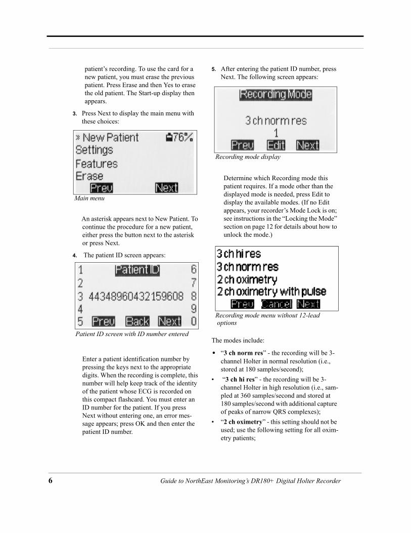
3. Press Next to display the main menu with these choices:
An asterisk appears next to New Patient. To continue the procedure for a new patient, either press the button next to the asterisk or press Next.
4. The patient ID screen appears:
Enter a patient identification number by pressing the keys next to the appropriate digits. When the recording is complete, this number will help keep track of the identity of the patient whose ECG is recorded on this compact flashcard. You must enter an ID number for the patient. If you press Next without entering one, an error mes-sage appears; press OK and then enter the patient ID number.
5. After entering the patient ID number, press Next. The following screen appears:
Determine which Recording mode this patient requires. If a mode other than the displayed mode is needed, press Edit to display the available modes. (If no Edit appears, your recorder’s Mode Lock is on; see instructions in the “Locking the Mode” section on page 12 for details about how to unlock the mode.)
The modes include:
• “3 ch norm res” - the recording will be 3-channel Holter in normal resolution (i.e., stored at 180 samples/second);
• “3 ch hi res” - the recording will be 3-channel Holter in high resolution (i.e., sam-pled at 360 samples/second and stored at 180 samples/second with additional capture of peaks of narrow QRS complexes);
• “2 ch oximetry” - this setting should not be used; use the following setting for all oxim-etry patients;
Main menu
Patient ID screen with ID number entered
Recording mode display
Recording mode menu without 12-lead options
Guide to NorthEast Monitoring’s DR180+ Digital Holter Recorder

Guide
Preparing the Recorder
• “2 ch oximetry with pulse” - the recording will be 2-channel Holter in normal resolu-tion plus oximetry data (saved 3 times per second). Please note that if this setting is used, no pacemaker spikes will appear on the Holter recording and no pacemaker analysis will be done.
If your recorder has the 12-lead option, those choices also appear in the Recording mode menu, on three screen displays.
If you have the 12-lead option and choose the 10-electrode hookup, standard 3-channel
Holter signal is recorded, along with 12-lead data. For the Holter signal, channel 1 uses the V5 (+) and RA (-) electrodes; channel 2 uses V1 (+) and LA (-); channel 3 uses LL (+) and LA (-). The 12-lead options include these set-tings, defined as follows:
• “3 ch hi res 12L 1/3 min” means that the recording will be 3-channel Holter in high resolution plus one sample of 12-lead data every three minutes;
• “3 ch norm res 12L 1/3 min” means that the recording will be 3-channel Holter in normal resolution plus one sample of 12-lead data every three minutes;
• “3 ch norm res 12L 1/min” means that the recording will be 3-channel Holter in nor-mal resolution plus 12-lead data saved once every minute;
• “3 ch norm 12L 2/min” means that the recording will be 3-channel Holter in nor-mal resolution plus 12-lead data saved every 30 seconds;
• “3 ch norm 12L 1/18 sec” means that the recording will be 3-channel Holter in nor-mal resolution plus 12-lead data saved every 18 seconds; and
• “12L continuous” means that the recording will save continuous 12-lead data through-out the monitoring period. This setting is for research purposes only. For details about the settings available in continuous 12-lead, see the section “Recording contin-uous 12-lead” on page 13 of this manual.
Note: The DR180+ records 12-lead data with a sampling rate of 720 samples/second for three seconds per 12-lead strip, except when the recorder is set to the special research mode “12L continuous.”
Select the appropriate mode, then press Next.
Recording mode menu with 12-lead options - 1
Recording mode menu with 12-lead options - 2
Recording mode menu with 12-lead options - 3
to NorthEast Monitoring, Inc.’s DR180+ Digital Holter Recorder 7

8
6. The Lead Quality display appears:
This screen displays the signal quality for each lead, based on the level of impedance detected between the two electrodes for each channel. The best possible reading is 5; that indicates a good electrode-skin con-nection. Reapply the electrodes for any channel that has a reading of less than 4.
For oximetry patients, there may be a delay in the “spo2” display in lead quality.
7. Press Next to review the signal currently being detected in channel 1. Press Next to cycle through the three (or 12) leads. Exam-
ine the signal on each lead for proper ampli-tude, electrode placement, and lack of artifact:
8. Once a satisfactory signal is displayed in all channels, press Start. Recording begins and will continue until the batteries are removed or the compact flashcard is full. During recording, a time-of-day clock appears on the LCD.
9. Instruct the patient how to indicate symp-tomatic events during the recording. Details appear in the following section.
10. When the patient returns, remove the elec-trodes, leads and recorder from the patient. Remove the batteries and compact flashcard from the recorder. The Holter signal is now ready to be analyzed.
How Patients use the Event ButtonIf you choose, the patient can use the Event but-ton on the recorder to mark the Holter signal at times the patient feels symptoms or is perform-ing particular activities.
Lead Quality display for three channels
Lead Quality display for12-lead
Lead Quality display for oximetry
Holter signal in channel 1
DR180+ display during recording
Guide to NorthEast Monitoring’s DR180+ Digital Holter Recorder
Guide
Erasing a Compact Flashcard
When the patient pushes the Event button dur-ing the recording, the signal is marked with an Event marker and, when the recording is ana-lyzed, the strip with the Event marker is saved during Holter analysis. After pressing the Event button, the patient can indicate the symp-tom or activity at that time; when analyzed, that symptom or activity is saved as the strip label.
Pre-programmed symptoms and activities include: Bathroom, Chest Pain, Chest Pressure, Dizzy, Driving, Eating, Event, Exercise, Housework, Lying down, Medications, Palpita-tions, Rapid heart rate, Sex, Short of breath, Sitting down, Skipped beat, Standing, Up/Down stairs, Walking, and Went to bed. These choices appear on two separate LCD displays.
Additional choices can be customized for your recorders using NorthEast’s Configuration pro-gram. See the Configuration chapter in your Holter LX Software operator’s manual for details about changing the Event choices.
To use the Event button:
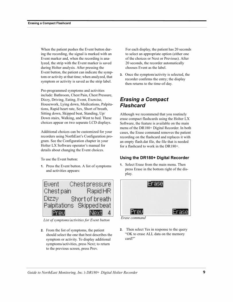
1. Press the Event button. A list of symptoms and activities appears:
2. From the list of symptoms, the patient should select the one that best describes the symptom or activity. To display additional symptoms/activities, press Next; to return to the previous screen, press Prev.
For each display, the patient has 20 seconds to select an appropriate option (either one of the choices or Next or Previous). After 20 seconds, the recorder automatically chooses Event as the label.
3. Once the symptom/activity is selected, the recorder confirms the entry; the display then returns to the time-of-day.
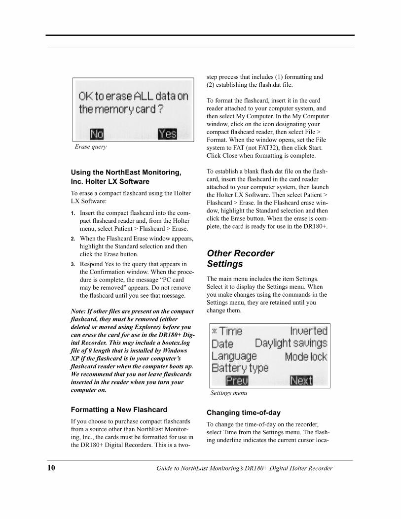
Erasing a Compact FlashcardAlthough we recommend that you routinely erase compact flashcards using the Holter LX Software, the feature is available on the main menu of the DR180+ Digital Recorder. In both cases, the Erase command removes the patient recording on the flashcard and replaces it with an empty flash.dat file, the file that is needed for a flashcard to work in the DR180+.
Using the DR180+ Digital Recorder1. Select Erase from the main menu. Then
press Erase in the bottom right of the dis-play.
2. Then select Yes in response to the query “OK to erase ALL data on the memory card?”
List of symptoms/activities for Event button Erase command
to NorthEast Monitoring, Inc.’s DR180+ Digital Holter Recorder 9
10
Using the NorthEast Monitoring, Inc. Holter LX SoftwareTo erase a compact flashcard using the Holter LX Software:
1. Insert the compact flashcard into the com-pact flashcard reader and, from the Holter menu, select Patient > Flashcard > Erase.
2. When the Flashcard Erase window appears, highlight the Standard selection and then click the Erase button.
3. Respond Yes to the query that appears in the Confirmation window. When the proce-dure is complete, the message “PC card may be removed” appears. Do not remove the flashcard until you see that message.
Note: If other files are present on the compact flashcard, they must be removed (either deleted or moved using Explorer) before you can erase the card for use in the DR180+ Dig-ital Recorder. This may include a bootex.log file of 0 length that is installed by Windows XP if the flashcard is in your computer’s flashcard reader when the computer boots up. We recommend that you not leave flashcards inserted in the reader when you turn your computer on.
Formatting a New FlashcardIf you choose to purchase compact flashcards from a source other than NorthEast Monitor-ing, Inc., the cards must be formatted for use in the DR180+ Digital Recorders. This is a two-
step process that includes (1) formatting and (2) establishing the flash.dat file.
To format the flashcard, insert it in the card reader attached to your computer system, and then select My Computer. In the My Computer window, click on the icon designating your compact flashcard reader, then select File > Format. When the window opens, set the File system to FAT (not FAT32), then click Start. Click Close when formatting is complete.
To establish a blank flash.dat file on the flash-card, insert the flashcard in the card reader attached to your computer system, then launch the Holter LX Software. Then select Patient > Flashcard > Erase. In the Flashcard erase win-dow, highlight the Standard selection and then click the Erase button. When the erase is com-plete, the card is ready for use in the DR180+.
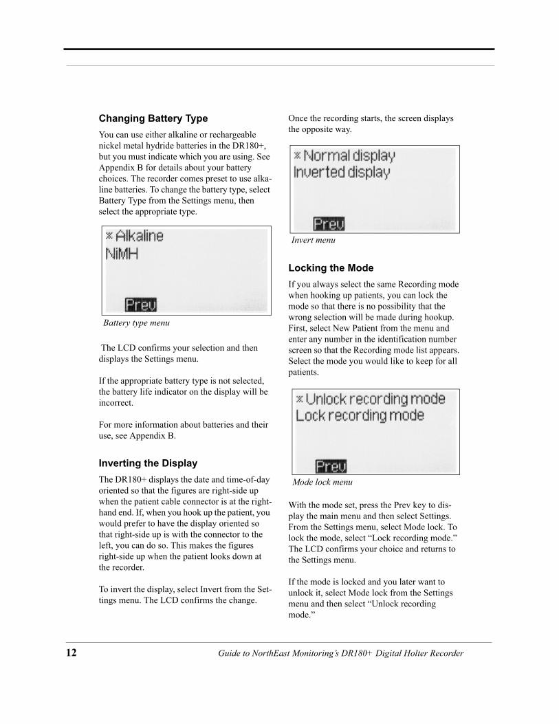
Other Recorder SettingsThe main menu includes the item Settings. Select it to display the Settings menu. When you make changes using the commands in the Settings menu, they are retained until you change them.
Changing time-of-dayTo change the time-of-day on the recorder, select Time from the Settings menu. The flash-ing underline indicates the current cursor loca-
Erase query
Settings menu
Guide to NorthEast Monitoring’s DR180+ Digital Holter Recorder

Guide
Other Recorder Settings
tion. Type over the existing time-of-day, using the 24-hour format of HH:MM.
After you enter the correct time, press Save. The LCD returns to the Settings menu. From there, press Prev to display the Main menu.
The DR180+ can detect the onset and end of Daylight Savings Time so that the time-of-day can change appropriately. To enable the shift to or from Daylight Saving Time, select Daylight Savings from the Settings menu.
The Daylight Savings feature means that the first time you turn on the recorder after the shift to or from Daylight Savings Time, you will be asked whether to “Set clock forward for Day-light Savings” or to “Set clock back from Day-light Saving.” To change the time-of-day appropriately, press Yes. To not change the time-of-day, press No. To turn off the feature, select Disable daylight savings from the Day-light savings menu.
Changing the DateTo change the date on the recorder, select Date from the Settings menu. The flashing underline indicates the current cursor location. Type over the existing date, using the format YYYY-MM-DD, where YYYY is the 4-digit year, MM is the 2-digit month and DD is the 2-digit day. You do not type the hyphens. After you enter the correct date, press Save. The LCD returns to the Settings menu.
Changing LanguageTo change the language used on the recorder, select Language from the Settings menu. The following languages are displayed:
Select the appropriate language from the list by pressing the key next to it. The DR180+ con-firms your selection and then displays the Set-tings menu in that language.
Time-of-day display
Daylight savings menu
Date display
Language selection menu
to NorthEast Monitoring, Inc.’s DR180+ Digital Holter Recorder 11
12
Changing Battery TypeYou can use either alkaline or rechargeable nickel metal hydride batteries in the DR180+, but you must indicate which you are using. See Appendix B for details about your battery choices. The recorder comes preset to use alka-line batteries. To change the battery type, select Battery Type from the Settings menu, then select the appropriate type.
The LCD confirms your selection and then displays the Settings menu.
If the appropriate battery type is not selected, the battery life indicator on the display will be incorrect.
For more information about batteries and their use, see Appendix B.
Inverting the DisplayThe DR180+ displays the date and time-of-day oriented so that the figures are right-side up when the patient cable connector is at the right-hand end. If, when you hook up the patient, you would prefer to have the display oriented so that right-side up is with the connector to the left, you can do so. This makes the figures right-side up when the patient looks down at the recorder.
To invert the display, select Invert from the Set-tings menu. The LCD confirms the change.
Once the recording starts, the screen displays the opposite way.
Locking the ModeIf you always select the same Recording mode when hooking up patients, you can lock the mode so that there is no possibility that the wrong selection will be made during hookup. First, select New Patient from the menu and enter any number in the identification number screen so that the Recording mode list appears. Select the mode you would like to keep for all patients.
With the mode set, press the Prev key to dis-play the main menu and then select Settings. From the Settings menu, select Mode lock. To lock the mode, select “Lock recording mode.” The LCD confirms your choice and returns to the Settings menu.
If the mode is locked and you later want to unlock it, select Mode lock from the Settings menu and then select “Unlock recording mode.”
Battery type menu
Invert menu
Mode lock menu
Guide to NorthEast Monitoring’s DR180+ Digital Holter Recorder
Guide
Recording Continuous 12-lead
Features Menu ItemThe Features item in the menu displays the serial number of your DR180+ and any optional features.
Power Loss Protection FeatureIf anyone removes the batteries during the recording and then re-inserts them, the record-ing will continue as long as the batteries are replaced within one hour of removal. When the batteries are re-inserted, the LCD shows a countdown display starting at 15. Once the countdown is complete, the DR180+ continues to record the patient’s Holter signal.
When the patient’s recording is analyzed, the signal recorded while the batteries were not in place appears as continuous high-frequency artifact in all channels.
If the recorder is no longer attached to a patient and you want to stop the recording, you can interrupt the countdown by pressing the five buttons on the left of the LCD, one after another, from the top to the bottom. Be sure to press each button only once. You may or may not hear a beep when you press the top button; just continue to the next. After you press the bottom one of the five, the message “Previous recording found” appears. Press Erase and then Yes to erase the compact flashcard and then display the Start-up screen.
Recording Continuous 12-leadThe Recording mode selection “12L continu-ous” is for research purposes only. In the con-tinuous 12-lead mode, you have control over additional parameters used during the record-
ing, including sample rate, number of channels sampled, interval between segments, and length of each recorded segment. When that selection is made from the Recording mode menu, the following display appears:
The current settings are indicated to the right of the display. To change a setting, select the appropriate button to the left of the setting to be changed. Details of each setting are explained in the following sections.
Rate This refers to the sampling rate for the 12-lead strips. Sampling rates (samples/second) of 180, 360 or 720 are the choices. Each choice directly affects the highest frequency recorded and the amount of memory used. The 90% points in the frequency response for these three sample rates are 45, 90 and 180 hertz, respec-tively.
Continuous 12-lead Settings menu
Rate display in continuous 12-lead
to NorthEast Monitoring, Inc.’s DR180+ Digital Holter Recorder 13
14
In the Rate display, the blinking underline appears to the right of the current setting and the possible entries appear in the line below. Use the Back key to erase each character of the current setting and then use the numeric keys to enter a new one. When you have typed your entry, press Save.
Chan(nel)s The number of channels continuously recorded can be 2, 3, 4 or 9.
In the Chans display, the blinking underline appears to the right of the current setting and the possible entries appear in the line below. Use the Back key to erase each character of the current setting and then use the numeric keys to enter a new one. When you have typed your entry, press Save.
If you set Chans to 9, all recording is done in the conventional 12-lead configuration using RL as the reference lead and nine signal leads. If you set Chans to 2, 3 or 4, then that number of differential channels are recorded. The lead
configurations in the differential lead modes are:
Note:* indicates a lead not used by the same differential channel. To use the lead quality indicator during hookup, this lead must be either connected to a patient electrode or be connected to the reference lead (RL).
Interval The Interval setting indicates how often contin-uous 12-lead data is saved. One sample is saved after the number of seconds set here; the setting indicates the number of seconds between the beginnings of sequential record-ings.
Chans display in continuous 12-lead
Differential lead configurations
Channel 12-lead cable
3-lead cable
Lead quality column
1 + V5 1 + V5/RA
1 - RA 1 - V5/RA
2 + V1 2 + V1/LA
2 - LA 2 - V1/LA
3 + LL 3 + LL/LA*
3 - V2 3 - V1*/V2
4 + V6 none V5*/V6
4 - V4 none V3*/V4
Interval display in continuous 12-lead
Guide to NorthEast Monitoring’s DR180+ Digital Holter Recorder
Guide
In the Interval display, the blinking underline is to the right of the current entry, with the units (seconds) below the entry. To change the entry, use the Back key to erase the characters in the setting and use the numeric keys to enter a new one. After typing your entry, press Save.
Note: If “Interval” and “Length” are set to zero, the 12-lead recording is continuous with no interruptions.
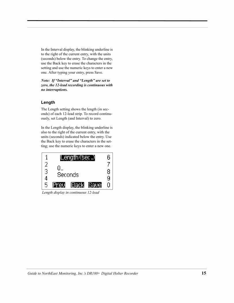
LengthThe Length setting shows the length (in sec-onds) of each 12-lead strip. To record continu-ously, set Length (and Interval) to zero.
In the Length display, the blinking underline is also to the right of the current entry, with the units (seconds) indicated below the entry. Use the Back key to erase the characters in the set-ting; use the numeric keys to enter a new one.
Length display in continuous 12-lead
to NorthEast Monitoring, Inc.’s DR180+ Digital Holter Recorder 15

16
Memory Requirements for 12-Lead Recordings
Recording type
Channels recorded
Sampling rate
MB/hr.
MB/24 hr.
MB/48 hr.
12 lead 9 720 23.99 575.87 1151.74
4 bipolar 4 720 11.03 264.83 529.66
3 bipolar 3 720 8.44 202.62 405.25
2 bipolar 2 720 5.85 140.42 280.83
12 lead 9 360 12.33 295.94 591.87
4 bipolar 4 360 5.85 140.42 280.83
3 bipolar 3 360 4.55 109.31 218.62
2 bipolar 2 360 3.26 78.21 156.42
12 lead 9 180 6.50 155.97 311.94
4 bipolar 4 180 3.26 78.21 156.42
3 bipolar 3 180 2.61 62.66 125.31
2 bipolar 2 180 1.96 47.10 94.21
Recording type
Channels recorded
Sampling rate
MB/hr.
MB/24 hr.
MB/48 hr.
12 lead 9 720 4.55 109.31 218.62
4 bipolar 4 720 2.39 57.47 114.94
3 bipolar 3 720 1.96 47.10 94.21
2 bipolar 2 720 1.53 36.74 73.47
12 lead 9 360 2.61 62.66 125.31
4 bipolar 4 360 1.53 36.74 73.47
3 bipolar 3 360 1.31 31.55 63.10
2 bipolar 2 360 1.10 26.37 52.74
12 lead 9 180 1.64 39.33 78.66
4 bipolar 4 180 1.10 26.37 52.74
3 bipolar 3 180 .99 23.78 47.55
2 bipolar 2 180 .88 21.18 42.37
The amount of compactflashcard memory neededfor a continuous 12-leadrecording is a function ofthe number of channels andthe sample rate. If Lengthand Interval in the 12Lcontinuous mode are set tozero, the memory table at the right applies:
In addition, if the Lengthand Interval settings in the 12L continuous modeare not set to zero (forcontinuous recording), thememory requirement isreduced to approximatelythe fraction of timerecorded. For example, ifthe Length is set to 10and Interval to 60 (that is,a 10-second strip issaved every minute), approximately one-sixthof the memory is needed,when compared to a continuous 12-leadrecording over the sameperiod. The table at leftshows the compact flashcard memory requirements for 12L continuous with Interval set.to 60 and Length set to 10.
Guide to NorthEast Monitoring’s DR180+ Digital Holter Recorder

Guide
Processing Data Collected in Continuous 12-lead Modes
Processing Data Collected in Continuous 12-lead ModesRecording made using any 12-lead continuous mode require additional processing of the data to use it in the Holter LX system. It is also pos-sible to convert the data into a form that can be used for analysis by another application. Doing the conversion uses a number of command-line utilities, so a knowledge of the operating sys-tem directory structures and command-line operations is required.
The options depend on the mode in which the data was recorded.
Recordings in 9-channel ModeIn this mode, the options are (1) to have the Holter LX program convert the data into sepa-rate 3-second strips or (2) to use separate utili-ties to convert the data into files for analysis by other methods.
To convert the continuous data into separate 3-second strips, a setting in the “Research set-tings” window must be accessed. For instruc-tions about accessing the Research settings window, contact the toll-free NorthEast Moni-toring, Inc. support line at 866-346-5837.
In the Research settings window, the Continu-ous Interval field should be set to the time desired between the start of the 3-second strips. Because the system does not allow the strips to overlap, the value entered must be 4 seconds or greater. When analysis is then started, the sys-tem will generate a 3-second strip of a 12-lead presentation at the interval selected.
If the Length and Interval settings in 12L con-tinuous are not set to zero during the recording, then the time at the start of each strip saved will
be measured from the beginning of each recording period. That means that if the record-ing was originally made with a length of 10 seconds every minute, and for analysis you set Continuous Interval to 4, a strip will be saved (1) at the beginning of each 10-second interval, (2) at 4 seconds into the interval, and (3) a par-tial strip starting 8 seconds into the interval. Because of these partial strips, we recommend that the Continuous Interval value be set to an integer factor of the interval length. In this case, that would be 5 seconds.
Recordings made using 180 and 360 samples per second rates will be automatically up-sam-pled for use in the Holter LX 12-lead display. While this generates 720-samples-per-second files, the data is still limited by the bandwidth limitations of the original recording.
Conversion Options for all ModesAll recordings made using one of the 12-lead continuous modes can be converted to binary files for use by other applications. All con-verted files are in the form of 16-bit binary samples or 2 bytes per sample with the least significant byte first. The data are right-justi-fied n the data word, and scaling is such that a count of one least significant bit corresponds to an input value of 6.25 microvolts.
The utilities available for data format conver-sion are “procfl.exe” and “conhires.exe,” usu-ally in the \nm\bin directory of the Holter LX installation. The procfl.exe program converts the data on the compact flashcard to a set of files that can then be used by conhires.exe to generate the final binary files. Both programs display their instructions from the command line in the nm\bin directory. From the com-mand line, type either: procfl ? or conhires and then press the Enter key.
to NorthEast Monitoring, Inc.’s DR180+ Digital Holter Recorder 17

18
Using \nm\bin\procflThe call uses one of two formats:
• profl [options] [base_path] [flash_path] [max_hours] [EGM_sample_offset]
• profl [-ooptions] [-bbase_path] [-fflash_path] [-mmax_hours] [-eEGM_sample_offset] [-l12_lead_interval_period]
Options is the sum of:
1 - convert EMG file to 180 samples per sec-ond format
2 - put markers in the form of the waveforms in markerwv.dat
4 - output debug information
8 - convert all ECG data directly to a datac-ard.dat file (in place of flashcx.dat file); this should not be used with options 1 and 2
16 - output EMG files in 8-bit format; this should not be used with option 1
32 - output add_datacard debug
64 - output recorder debug file
Base_path is the path to be used for all files unless the flash_path is specified.
Flash_path is to be used as the path only for the flash.dat input file. Flash.dat will be copied to base_path if base_path !=flash_path.
Max_hours is the maximum number of hours to be converted (50 is used if this is not speci-fied). Use 0 for cleric file only.
EGM_sample_offset is the number of samples added to the time of the EGM data for time alignment.
12_lead_interval_period is the time in sec-onds between simulated 12-lead records made from continuous 12-lead data (using 12-lead modes only).
Using \nm\bin\conhiresUse the format:
• conhires mode outfiles-path infile-path
Mode choices include:
0 - to generate 9 files of 16-bit binary data cor-responding to the 9 patient leads
1 - to generate 12 files of standard 12-lead for-mat in 16-bit binary format (only valid for modes 13, 16, 19)
2 - to generate 1 file of standard 12-lead format in 16-bit binary records of 12 words per sample
+8 - all modes to output in ASCII format
Conhires converts the hires.dat file from procfl to separate files for further processing. The input is hires.dat and the output is n files each of 16-bit samples reconstructed from the sequential channel in hires.dat. Paced markers are indicated by a data value replaced by 0x8000. Time values are inserted in the data as 32-bit times, starting as 0 at the beginning of the dataset. The time resolution is 1/320 sec-onds. The time value is preceded by the value 0x8001.
Processing ProcedureNormal use of the programs procfl and con-hires would consist of running them in sequence, like this:
• procfl -ff: -btmp• conhires mode tmp
In those commands:
F: is the drive that the compact flashcard is in or is the full path (including “flash.dat”) to the flash.dat file if that file has been copied from the compact flashcard to another location.
Tmp is the path of a temporary directory for the scratch files and the final files. Note that if
Guide to NorthEast Monitoring’s DR180+ Digital Holter Recorder
Guide
Error Messages
processing is being done as a part of the Holter LX system, it is possible to leave these files in the normal patient directories (normally in the form \nm\pat\xx, where xx is the number of the patient directory).
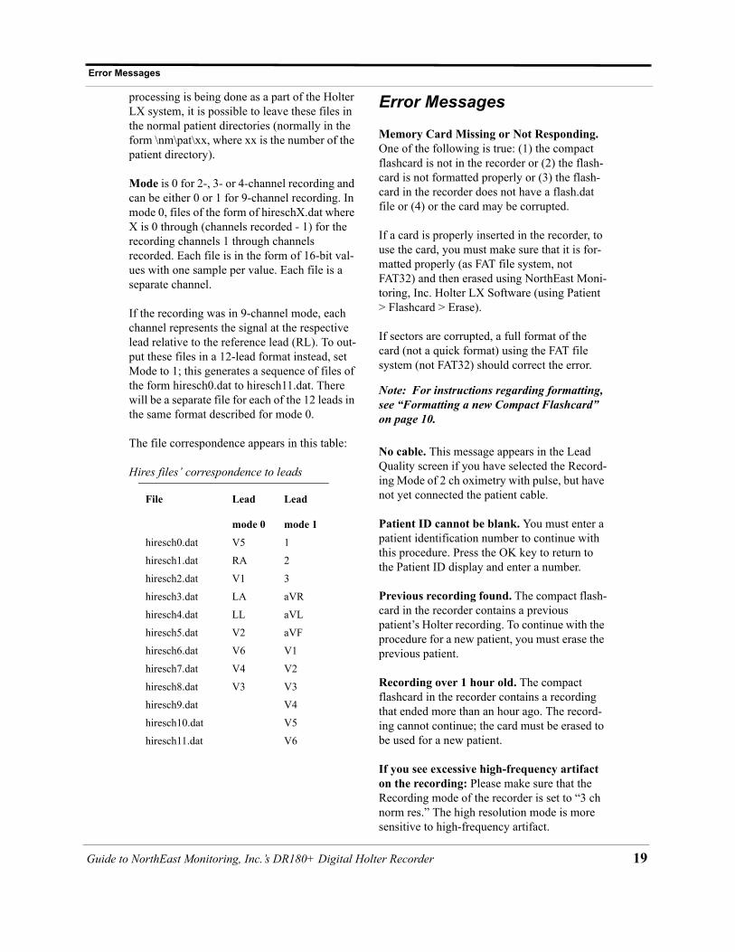
Mode is 0 for 2-, 3- or 4-channel recording and can be either 0 or 1 for 9-channel recording. In mode 0, files of the form of hireschX.dat where X is 0 through (channels recorded - 1) for the recording channels 1 through channels recorded. Each file is in the form of 16-bit val-ues with one sample per value. Each file is a separate channel.
If the recording was in 9-channel mode, each channel represents the signal at the respective lead relative to the reference lead (RL). To out-put these files in a 12-lead format instead, set Mode to 1; this generates a sequence of files of the form hiresch0.dat to hiresch11.dat. There will be a separate file for each of the 12 leads in the same format described for mode 0.
The file correspondence appears in this table:
Error Messages
Memory Card Missing or Not Responding. One of the following is true: (1) the compact flashcard is not in the recorder or (2) the flash-card is not formatted properly or (3) the flash-card in the recorder does not have a flash.dat file or (4) or the card may be corrupted.
If a card is properly inserted in the recorder, to use the card, you must make sure that it is for-matted properly (as FAT file system, not FAT32) and then erased using NorthEast Moni-toring, Inc. Holter LX Software (using Patient > Flashcard > Erase).
If sectors are corrupted, a full format of the card (not a quick format) using the FAT file system (not FAT32) should correct the error.
Note: For instructions regarding formatting, see “Formatting a new Compact Flashcard” on page 10.
No cable. This message appears in the Lead Quality screen if you have selected the Record-ing Mode of 2 ch oximetry with pulse, but have not yet connected the patient cable.
Patient ID cannot be blank. You must enter a patient identification number to continue with this procedure. Press the OK key to return to the Patient ID display and enter a number.
Previous recording found. The compact flash-card in the recorder contains a previous patient’s Holter recording. To continue with the procedure for a new patient, you must erase the previous patient.
Recording over 1 hour old. The compact flashcard in the recorder contains a recording that ended more than an hour ago. The record-ing cannot continue; the card must be erased to be used for a new patient.
If you see excessive high-frequency artifact on the recording: Please make sure that the Recording mode of the recorder is set to “3 ch norm res.” The high resolution mode is more sensitive to high-frequency artifact.
Hires files’ correspondence to leads
File Lead Lead
mode 0 mode 1
hiresch0.dat V5 1
hiresch1.dat RA 2
hiresch2.dat V1 3
hiresch3.dat LA aVR
hiresch4.dat LL aVL
hiresch5.dat V2 aVF
hiresch6.dat V6 V1
hiresch7.dat V4 V2
hiresch8.dat V3 V3
hiresch9.dat V4
hiresch10.dat V5
hiresch11.dat V6
to NorthEast Monitoring, Inc.’s DR180+ Digital Holter Recorder 19
20
Appendix A: Maintenance and Care of the DR180+ Digital RecorderPlease follow these instructions to care for the DR180+:
Clean the outside of the recorder with a damp soft cloth. DO NOT use any abrasive cleaners, such as acetone, on the outside of the recorder.
Do not remove the cable from the recorder after each use.
Do not wrap the lead wires tightly around the recorder after each use.
Do not clean the cable with harsh chemicals, such as acetone.
Do not pull on or stretch the cables when clean-ing them or when hooking up a patient.
Do not submerge the recorder or its cables in water.
Replace the cable on a regular basis or at the first sign of damage.
In cases of infection control, refer to your infection control department. Sani-Cloth ger-micidal surface wipes are recommended.
Do not store the recorder at temperatures below 45 degrees F or above 100 degrees F (between 5 and 45 degrees C).
Warranty Repairs
Please contact your dealer first prior to return-ing a recorder for repair, to determine the war-ranty period, conditions and exclusions. If your dealer is unavailable, contact:
NorthEast Monitoring, Inc.Two Clock Tower Place, Suite 360Maynard MA [email protected]
Prior to returning a recorder, you must obtain a return authorization (RMA) number. This RMA number must be visible on the outside of the packing carton; otherwise, NorthEast will refuse delivery.
The DR180+ contains no user-serviceable parts.
Removing the label or opening the recorder voids the warranty.
Guide to NorthEast Monitoring’s DR180+ Digital Holter Recorder
Guide
Appendix B: Batteries for the DR180+ Digital Recorder
Appendix B: Batteries for the DR180+ Digital Recorder
The DR180+ recorders use two AA size batter-ies. This requirement may be fulfilled in a number of ways. Battery types available on the market are:
• Alkaline (example: Eveready Energizer E91, Duracell NM1500)
• Heavy Duty• Nickel Medal Hydride (example: MAHA
AA 1800 mAh, Rayovac 1600 mAh NiMH)• Nickel Cadmium (NiCd)• Lithium (example: Eveready L91)
Alkaline
The alkaline is the most common type of bat-tery. When a new properly stored battery is used, a recording time of 50-60 hours can be expected. With this type of battery a recording time of 24 or 48 hours can be reliably obtained. While a recording that runs for 24 hours will in theory use slightly less than half the capacity of the battery, using a battery for two 24-hour recordings is not recommended. The risk of the first recording being slightly in excess of 24 hours will lead to frequent "second" recordings that do not reach 24 hours.
The primary limitation of this battery type is that there is only a limited ability to test the battery before it is used. When it is inserted into the recorder, the recorder does an evalua-tion of the capacity of the battery and indicates that on the display. Unfortunately, at times a defective battery will appear to initially have full capacity but will fail well before the expected time. The probability of this type of failure is very small when the batteries are obtained from the primary suppliers.
The best prevention available against defective batteries is to obtain them from suppliers who do not store them for a long time and do store them properly. There are few requirements for storage of alkaline batteries. They should be stored at "room" temperatures (50-90F) and in a dry location. There is no advantage to storing them in a refrigerator. There is actually a sig-nificant problem with low temperature storage. Normal refrigerators have a very high humidity inside; this can cause a much greater reduction of life that is gained by the lower temperatures. In addition, storage at a temperature below freezing will reduce battery life.
Heavy Duty
Batteries that are labeled "Heavy Duty" vary widely in capacity. The use of "Heavy Duty" batteries is not recommended.
Nickel Metal Hydride(NiMH)
This class of batteries is rechargeable and thus can be used in situations where a disposable battery is not desirable. Batteries of this type come in a range of capacities with the labeled capacity ranging from 1100 to 1800 mAh (mil-liamp hours). It is recommended that only bat-teries with a rating of at least 1500 mAh be used. Lower capacity batteries will operate the recorder for 24 hours when they are new but after only a few uses may not be able to operate for the full 24 hours.
Charging these batteries is the most difficult part of their use. Only chargers that are specifi-cally rated for use with NiMH batteries should be used such as the MAHA MH-204F or Ray-ovac 1-Hour charger. Older chargers designed only for NiCd (Nickel Cadmium) will over-charge this type of battery and can significantly shorten battery life. A charger that applies an excessive continuous charge can also shorten the battery life. If in doubt it is best not to leave
to NorthEast Monitoring, Inc.’s DR180+ Digital Holter Recorder 21

22
the batteries on charge for long periods of time after the charger indicates a full charge.
Unlike the older rechargeable battery types, NiMH batteries have no real "memory." Thus they do not need to be completely discharged or "conditioned" to insure that they will fully charge. Doing a complete discharge will reduce the total life of the battery as every time the battery is discharged below about 25% capacity, the life of the battery is shortened more than for a normal discharge cycle.
Most chargers for NiMH batteries depend on a property of these batteries that causes them to heat up when they have reached full charge. This has two consequences. First, if the batter-ies are being charged in pairs, the first battery to be fully charged will heat up and shut down the charge cycle. This can leave one of the bat-teries partially charged. Thus it is best to keep pairs of batteries together so they are both dis-charged and charged together. Secondly, if the battery is too warm for any reason, it may shut down the charge early. For that reason the bat-teries should be charged at normal room tem-peratures and it is often best not to cover the batteries in any way during the charge. Even the charger's own cover may reduce the charge. Leave the cover open during charging.
When the battery is not being charged, it will slowly discharge by itself. This type of battery will lose about one percent of its charge for each day. Most chargers will bring a partially charged battery up to full capacity in under an hour. Batteries that have not been used for over two weeks should be charged before use.
If used properly, these batteries will last for 300 to 1000 recordings of 24 hours each. They will still not last forever. To control battery life, writing the date on the battery that the batteries are first put in service can be helpful.
Nickel Cadmium
This type of battery does not have enough capacity to reliably run the recorder for 24 hours and are not recommended.
Lithium
There is one type of lithium battery that can be used in the DR180+ recorder. It is the Eveready L91. These batteries have somewhat more capacity than an alkaline battery. This will allow a 72-hour recording to be made without changing the battery. The safety mar-gin when doing such a recording is very small and such recordings should be made only if the consequences of losing a small amount of time at the end of the recording period are not sig-nificant.
There is no selection in the battery type set-tings for this battery type. Although you can use the Alkaline setting if you use lithium bat-teries, please note that the battery condition indication is not valid when these batteries are used. In addition, at the end of the recording, the recorder may record a few minutes of data that is corrupted before shutting down. When this type of error occurs, there normally is no clear R-wave present at the end of the record-ing.
Another benefit of this battery type is an extremely long shelf life. These batteries will lose very little capacity after up to five years of storage.
This type of battery is very expensive and there may be some situations where the use of lith-ium batteries is not permitted. Thus they should only be used if absolutely needed.
Guide to NorthEast Monitoring’s DR180+ Digital Holter Recorder
Guide
Appendix C: Pacemaker Detection with the DR180+ Digital Recorder
Appendix C: Pacemaker Detection with the DR180+ Digital Recorder
The DR180+ recorders have a built-in pace-maker detection capability. This was designed to overcome some of the problem inherent with the analysis of Holter recordings from patients with pacemakers.
A pacemaker is designed to initiate cardiac conduction by stimulating a spot on the myo-cardium with a pulse of 1-4 volts and a dura-tion of typically 250 to 2000 microseconds. When this pulse is seen at the surface recording electrodes it is significantly attenuated. For patients with a unipolar electrode configura-tion, the signal at the surface may range from under 50 to over 200 millivolts. When a bipolar lead configuration is used, the signal is typi-cally much lower and is in the range of 3 to 50 millivolts. Especially with the bipolar leads, the signal size is dependent on the positions of the pacemaker lead and the surface electrodes.
The amplitude of the signal being referred to here is not the size of the "spike" commonly seen on an ECG cart or bedside monitor. Since the duration of the pulse is short compared to a QRS complex, normal ECG recorders will greatly attenuate the signal; in some cases it cannot be seen at all. Also, some ECG record-ers have devices which enhance the pace pulse to insure that it will be displayed. Only very wide bandwidth recorders as are sometimes used in an electro-physiology study will show the unmodified full amplitude of the pulse.
The DR180+ recorder has the wide bandwidth ECG amplifiers necessary to pass the pace-maker pulse. Since the pulse would still be too short to be recorded in a reliable manner at any practical sampling rate for Holter recording, the pulse is detected by the recorder. The time of the pulse is then digitally stored along with the Holter ECG data. When the data is ana-
lyzed, the pacemaker pulse is displayed and used for the analysis.
At recording time it is desirable to have the recorder be as sensitive to the pacemaker pulse as possible so pulses will not be missed. A con-flicting requirement is that there should be as few false pacemaker detections as possible.
False pacemaker detections are primarily caused by electrical events. Any external elec-trical signal that is coupled to the patient elec-trodes which looks like a pacemaker pulse will of necessity be stored by the recorder. The most common form of electrical signal that can look like a pacemaker signal is an electrostatic dis-charge (ESD) or "spark." These happen very frequently in dry weather but also occur, at a lower rate, under humid conditions.
Fortunately most ESD spikes as seen at the patient electrodes are of shorter duration or of lower amplitude than the real pacemaker pulses. While there is no absolute limit to the size or duration of the ESD pulses, the recorder ignores all pulses that are less than 150 micro-seconds long or are less than two millivolts in size. This signal is checked for in the four elec-trodes that are most commonly used (red and white, which are channel 1 + and -, respec-tively; and brown and black which are channel 2 + and -).
As pacemakers are normally programed to a pulse width greater than 150 microseconds, this does not cause a loss of detection. The require-ment that the pacemaker pulse be at least two millivolts in size is not a common problem. There are however occasional cases where the size of the pulse is marginal. To insure that the pacemaker is being detected, the detection is shown as a vertical line on the display of the ECG during the recorder setup. If the patient is frequently paced, the recorder's detection can be verified. In the infrequent cases that pace pulses are being missed, moving one of the listed electrodes will usually solve the problem.
to NorthEast Monitoring, Inc.’s DR180+ Digital Holter Recorder 23
24
Appendix D: DR 180+ Accessories
NEMCA126 - 5-Lead Patient cable
NEMCA123 - 7-Lead Patient cable
NEMCA124 - 12-Lead Patient cable
NEMCA130 - 5-Lead Shielded Patient cable
NEMCA131 - 7-Lead Shielded Patient cable
NEMCA132 - 5-Lead Shielded Patient cable (18” pediatric length)
NEMCA120 - Oximetry Cable
NEMP00267 - Nonin Probe
NEMP00269 - Nonin Adult Flex-wrap
NEMP00344 - Nonin Finger Clip
NEMP00345 - Nonin Ear Clip
NEMP00265 - 128 MB Flashcard
NEMH77- Holter Pouch
Guide to NorthEast Monitoring’s DR180+ Digital Holter Recorder

Index
Numerics12_lead_interval_period 1812L continuous 1312-lead 7, 14, 1912-lead continuous 1712-lead option 72 ch oximetry with pulse 73 ch hi res 63 ch hi res 12L 1/3 min 73 ch norm res 69-channel mode 17BBase_path 18Batteries 2, 5, 12, 13, 21Battery life 5Battery type 12
CCare of the DR180+ Digital Recorder 20Chan(nel)s 14Changing battery type 12Changing language 11Changing the date 11Changing time-of-day 10Channels 14Chans display 14Clock 8Compact flash card 2, 5Conhires 17, 18Continuous 12-lead 13, 17Conversion options 17Countdown display 13
DDate 11Daylight Savings Time 11Differential lead 14
EEGM_sample_offset 18Electrical Specifications 2Electrodes 2, 4, 5Erase 6, 9Error messages 19Event button 8, 9
FFAT 10Features 13File system 10Flash.dat 10Flash_path 18Flashcard Erase 10Format 10Formatting 10
HHires file 19
hires.dat 18Hooking up the Patient 3Hookup Procedure 3
IInterval 17Interval setting 14Invert 12Inverting the display 12
LLanguage 11Lead Quality 8Length 17Length setting 15Lock recording mode 12Locking the mode 12
MMain menu 6Maintenance 20Max_hours 18Memory Card Missing or not Responding 19Memory Requirements 16Memory requirements for 12-lead recordings 15Mode 19Mode Lock 6Mode lock 12
NNew Patient 6
OOperator Interface 2Options 18Oximetry 2, 4, 6, 7, 8
PPacemaker 23Patient cable 2,4Patient ID 6Patient ID cannot be blank 19Patient Leads 2Physical specifications 2Power loss protection 13Preparing the recorder 5Previous recording found 13, 19Procfl 17, 18
RRate 13Recording mode 6, 12, 13Recording over 1 hour old 19Repair 20Research settings 17
SSampling rate for the 12-lead strips 13Settings 10Signal quality 8Start-up display 5Storage capacity 2Stress loop 5
TTime-of-day 10Tmp 18
UUnlock recording mode 12
WWarranty Repair 20
YYYYY-MM-DD 11
® MediMark Europe BP 2332F-38033 Grenoble Cedex 2. France