nonlinear control structure of grid connected …icrepq.com/icrepq17/501-17-hajizadeh.pdf ·...
TRANSCRIPT

International Conference on Renewable Energies and Power Quality (ICREPQ’17)
Malaga (Spain), 4th to 6th April, 2017 Renewable Energy and Power Quality Journal (RE&PQJ)
ISSN 2172-038 X, No.15 April 2017
Nonlinear Control Structure of Grid Connected Modular Multilevel Converters
A. Hajizadeh
1, L.E.Norum
2, A.Ahadpour Shal
3
1 Department of Energy Technology, Aalborg University
Campus of Esbjerg – Niels Bohr Vej 8, 6700 (Denmark)
E-mail: [email protected]
2 Department of Electric Power Engineering, Norwegian University of Science and Technology
O. S. Bragstads plass 2, Trondheim, Norway
E-mail: [email protected] 3 Faculty of Electrical Engineering and Information Technology, RWTH-Aachen University, Germany
E-mail: [email protected]
Abstract. This paper implements nonlinear control structure
based on Adaptive Fuzzy Sliding Mode (AFSM) Current Control
and Unscented Kalman Filter (UKF) to estimate the capacitor
voltages from the measurement of arm currents of Modular
Multilevel Converter (MMC). UKF use nonlinear unscented
transforms in the prediction step in order to preserve the
stochastic characteristics of a nonlinear system. In order to
design adaptive robust control strategy and nonlinear observer,
mathematical model of MMC using rotating d-q theory has been
used. Digital time-domain simulation studies are carried out in
the Matlab/Simulink environment to verify the performance of
the overall proposed control structure during different case
studies.
Key words
Nonlinear Control, Kalman Filter, Nonlinear observer, Modular
Multilevel Converter
1. Introduction
Power electronic converters should have a high reliability,
high efficiency, good harmonic performance, low cost,
and a small footprint. Modular Multilevel Converters
(MMC) are promising solutions for high power converters
since they allow the combination of excellent harmonic
performance and low switching frequencies [1-2].
Modular Multilevel Converter (MMC) is a new form of
multilevel converter and it is a big improvement in this
area especially for interconnection of High Voltage DC
(HVDC) transmission system and large wind farms [3].
Regarding to the many control complexities in MMC due
to modularity, high number of sub modules parameters
and limitation of measurements of all voltages and
currents, some control strategies have been present by
literatures which are categorized as control strategies of
MMC for submodule (SM) voltage balancing [4-5],
circulating current suppressing [6-7] and AC side current
control for grid connected application [8]. In most
presented works, the analysis of MMC during unbalanced
grid conditions has not been investigated. Moreover, a
comprehensive dynamic model for MMC that combines
symmetrical positive and negative sequences is needed to
design advanced control structures. Therefore, in
continuing of the proposed control strategies and for
making the MMC performance robust during unbalanced
grid conditions with unknown constant parameters, an
non-linear control structure for grid connected MMC is
proposed. The control structure is composed adaptive
fuzzy sliding mode (AFSM) control and non-linera
observer based on unscented kalman filter (UKF). Due to
high nonlinearities in model of MMC during unbalanced
grid condition, using of fuzzy sliding mode control is
proposed. An adaptive learning method also is added to
this structure to train the parameters of controller real-
time. In this structure, the capacitance value of the cell
capacitors as a uncertain parameter which should be
measured carefully. In order to design the observer, from
the developed nonlinear model of MMC, a nonlinear
observer based on unscented kalman filter (UKF) is
employed to estimate the capacitor voltage of each cell.
The unscented transform is a nonlinear transformation that
propagates the mean and covariance through a nonlinear
function. This method is based on a set of chosen sample
point, known as sigma points, and preserves the nonlinear
nature of the system. One way to handle nonlinear models
and transformations is to combine kalman filter with the
unscented transform to obtain the unscented kalman filter
[10]. This approach is very promising in power electronic
converters because their nonlinear model is known with
sufficient accuracy. The first measurement considered is
the arm currents which are the controlled variables and
makes it possible to estimate the capacitor voltages.
Afterward, it is necessary to know the dc-link voltage
state, because of the capacitors voltages references depend
on it. Finally, some illustrative simulation results of MMC
are demonstrated to confirm the feasibility of the proposed
PWM algorithm as well as the designed observer. This
https://doi.org/10.24084/repqj15.501 876 RE&PQJ, Vol.1, No.15, April 2017

paper is organized as follow. Section II presents the
MMC model. The discrete UKF and observer are
described in section III. In section IV, the control design
is proposed. Section V shows the simulation results.
Conclusion is given in section VI.
2. Modelling of Modular Multilevel
Converter
The typical structure of a MMC is shown in Fig. 1, and
the configuration of a SubModule (SM) is given in Fig.
2. Each SM is a simple chopper cell composed of two
IGBT switches (T1 and T2), two anti-parallel diodes (D1
and D2) and a capacitor C [2-3].
Fig.1 The typical structure of a MMC
Fig.2 Configuration of a SubModule (SM) fo MMC
From Figs.1 and 2, the mathematical equations
describing the dynamic behavior of a N-cells MMC
are expressed as follows:
1
2
1
_
_
1.
2
1.
2
1. 1,....,
1. 1,...., 2
i u
i
i
i
Np dc
i C p a
i
Nn dc
i C l n a
i N
C u
p i
C l
n i
di Vu V Ri V
dt L
di Vu V Ri V
dt L
dVi u i N
dt C
dVi u i N N
dt C
(1)
where ip, in ui, VCi_u VCi_l, and Va are upper/lower are
currents, gating signal of upper gate, upper and lower
capacitor voltages of the i-th cell, and phase a voltage
respectively.
3. Unscented Kalman Filter (UKF) and
Observer Design
The KF was originally developed for linear systems but
later applied to nonlinear systems using the linearized or
extended kalman filter (EKF) and its performance is
acceptable if the system nonlinearity is not severe. Its
simplicity, together with the popularity of the KF, makes
it the most widely applied nonlinear state estimator [10].
The discrete KF uses the first two statistical moments and
updates them with time. This is the key idea when
combining the UT and KF to obtain UKF. The UKF is
basically the discrete KF in which a UT is used to obtain
the mean and covariance updates. The UKF as presented
here is a simplified UKF which is suitable for estimation
of IM states. In general, the observation model can also
be nonlinear, and all parameters and functions can be
time varying. Moreover, the UKF can be extended to the
case of nonadditive noise [10]. The discrete-time
nonlinear system is given as follow:
1 ( , (k)) (k)x k f x k u (2)
and a linear measurement model
y(k)= H.x(k)+v(k) (3)
where x(k) is an n × 1 state vector, y(k) is an m × 1
measurement vector, H is the measurement matrix (m ×
n), and f(x(k),u(k)) is a known nonlinear state transition
vector. We assume that the process noise w(k) is white
and zero mean with covariance matrix Q and the
measurement noise v(k) is also white and zero mean with
covariance matrix R. We also have estimates of the initial
state (0)x
and the initial error covariance matrix (0)P .
The iterations in the classic KF consist of a prediction
step followed by a correction step. For the correction
step, we use the discrete KF equations
- T - T -1
+ - -
+ -
K(k +1)= P (k).H .(H.P (k).H + R)
x (k)= x (k)+ K k .(y(k)- H.x (k))
P (k)= (I - K(k).H).P (k)
(4)
where K(k) is the Kalman gain.
The prediction step in the KF is the projection of the
mean +
x (k) and covariance P (k) in time using the state
equation (recall that the KF estimates are unbiased). For
the nonlinear system of (1), the state equation is a
nonlinear transformation of a stochastic input x(k).
Hence, we can use the UT to obtain the mean x (k 1)
and covariance P (k 1) of its output. To use the discrete
KF, the MMC model is discretized by
solving the system’s state equation to determine the
states at the sampling instants. The resulting system is:
https://doi.org/10.24084/repqj15.501 877 RE&PQJ, Vol.1, No.15, April 2017

_
_
1
2
_
1
_
_ _
(k 1) (k) (k). (k) (k) (k)2
(k 1) (k) (k). (k) (k) (k)2
(k 1) (k) (k). (k) 1,....,
(k 1) (k) (k). (k
i
i
i i u
i i
Ns dc
p p i C u p a
i
Ns dc
n n i C l n a
i N
sC u C p i
sC l C l n i
T Vi i u V Ri V
L
T Vi i u V Ri V
L
TV V i u i N
C
TV V i u
C
) 1,...., 2i N N
(5)
Now, the state space model of MMC is related to the
UKF structure. The state vector is chosen as
_ _i u i lp n C CX i i V V
(6)
The arm currents are the measured output, and the
measurement is
1 0 0 0
0 1 0 0H
(7)
Thus, the measurement model is linear as in (3). Next,
the UKF observer is implemented using (3)-(4) to
accurately estimate the capacitor voltages.
4. Adaptive Fuzzy Sliding Mode Control
Design For the control plant given in (5), the sliding mode
control law can be derived in order to reach a desired
value of the output currents at sampling instants t=kT, the
following condition has to fulfilled.
(k) (k)
(k) (k)
ref
p p p
refn n n
S i i
S i i
(8)
Where ref
pi and ref
ni are the specified current vector
commands and S(k) = S(x(k)) represents the discrete-time
sliding-mode surface control and x(k) represents the
discrete state vector of the converter.
The sliding-mode control theory has been widely
employed to control nonlinear systems, especially the
systems that have model uncertainty and external
disturbance [11]. Robustness is the best advantage of a
sliding-mode control. It employs a noncontiguous control
effort to drive the system toward a sliding surface, and
then switches on that surface. Theoretically, it will
gradually approach the control objective, the origin of a
phase plane. The fuzzy logic controller needs only simple
computation and programming capacity to represent
human control behavior, and, in recent years, has had
widespread use in engineering applications. Since there is
a lack of theoretical modeling and analysis for the FLC
stability and robustness problem, the commercial
industrial application has progressed slowly. The fuzzy
system was used to approximate an optimal controller,
which was adjusted by an adaptive law based on
Lyapunov stability theory. However, this kind of direct
adaptive law is limited to the nonlinear system with
constant control gain. After that, the fuzzy direct control
scheme was proposed [12]. This control architecture
employed a fuzzy system to approximate an optimal
controller that was designed based on the assumption that
all the dynamics in the system were known, and then a
fuzzy sliding controller was added to the adaptive
controller for compensating the uncertainties and
smoothing the control signal.
Define, e is the phase plane variable. Then, the sliding
surface on the phase plane can be defined as:
1 1
2 2
•
ref ref
e ed ds = +l e = +
e edt dt
s = ( X - AX(t)- g(t)u)+ (X - X(t))
(9)
Based on the Lyapunov theorem, the sliding surface
reaching condition is .s s
0. If a control input u can be
chosen to satisfy this reaching condition, the control
system will converge to the origin of the phase plane.
From (5) and (9), it can be concluded that the variable
g(t) is always a positive/negative value for
charging/discharging conditions. It can also be found that
increases as decreases and vice versa in (7). If s 0, then
increasing u will result in decreasing .When the condition
is s 0, will decrease with the decreasing of u. Based on
this qualitative analysis, the control input can be designed
in an attempt to satisfy the inequality. Here, a new
control strategy with an FLC-based direct adaptive
controller is proposed, the control law of which is
generated directly from the output of an FLC. The
control voltage change for each sampling step is derived
from fuzzy inference and defuzzification calculation
instead of the equivalent control law derived from the
nominal model at the sliding surface. It can diminish the
chattering phenomenon of the traditional sliding-mode
control. The controller design does not need a
mathematical model and without constant gain limitation.
The block diagram is shown in Fig. 3. An online
parameters tuning algorithm is developed based on the
steep descent rule. The consequent parameters of the
FLC can be initially set to zero, then, the novel
parameters tuning algorithm is used to adjust the
consequent parameters to monitor the system control
performance. The sliding surface variable is employed as
the one-dimensional fuzzy input variable. The control
law is the output of the FLC which is a function of (A, s,
g(t), e, t) . Here, seven triangular membership functions
are used for the fuzzy input (s) and output (u) variables.
Since the proposed control strategy has on-line tuning
algorithm for fuzzy rules adjustment, the number of rules
is not critical.
Fig.3 Control system block diagram of an Adaptive Fuzzy
Sliding Mode Control
The minimum number of the rules is three for this control
strategy. Here, seven fuzzy rules are employed in this
https://doi.org/10.24084/repqj15.501 878 RE&PQJ, Vol.1, No.15, April 2017
control system to obtain appropriate dynamic response
and control accuracy. The input membership functions
are scaled into the range of -1 and 1 with equal span. The
control law is derived from the fuzzy inference decision
and defuzzification operation.
. .m m
j j j j
l l
m mj j
l l
U C
u
(10)
Where m is the rules number and Cj is the consequent
parameter. Which can be initially set to zero as a zero
fuzzy rule beginning. An adaptive rule is used to adjust
or update it. The adaptive rule is derived from the steep
descent rule to minimize the value of with respect to Cj.
Then, the modification equation of the parameter is
(t). (t)
(t)
j
j
s sC
C
(11)
where is the adaptive rate parameter. Based on the
chain rule, the above equation can be rewritten as
(t). (t) (t)
(t) (t)
(t)(t).s(t)
(t)
(t)(t)
(t)
j
j
j
j
mj
l
s s uC
u C
ug
C
s
(12)
where the adaptive rate parameter and the system input
parameter g(t) are combined as a learning rate parameter
. Then, the central positions of the defuzzification
membership functions can be regulated directly through
the modification of consequent parameter, Cj. Hence, it
achieves the objectives of online learning and fuzzy rules
adjustment. This adaptive rule has two main
contributions to this proposed model-free fuzzy sliding-
mode control. Firstly, it simplifies the implementation of
fuzzy control without trial-and-error process for finding
appropriate fuzzy rules. Secondly, this online adaptive
rule also has the effect of improving the stability property
and increasing the speed of reaching the sliding surface
due to the steep descent rule.
5. Simulation Results In order to evaluate the performance of the proposed
control strategy and nonlinear observer performance,
simulation results are carried out in MATLAB/Simulink
software with the nominal parameters given in Table I.
The set-points for the transferred real and reactive power
at t = 0 are set to 300 kW and 0 kVar , respectively. A
real power flow command is applied at t = 5 s by
changing the reference of real power to Pref = 200kW.
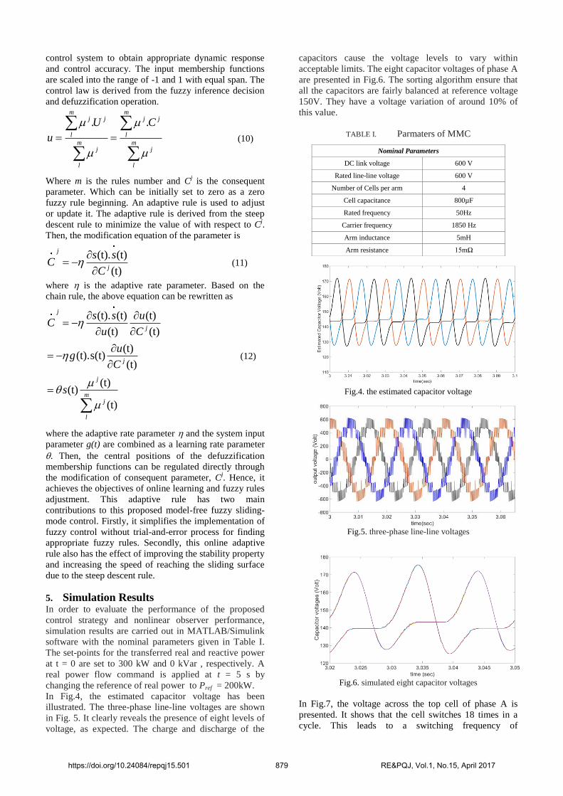
In Fig.4, the estimated capacitor voltage has been
illustrated. The three-phase line-line voltages are shown
in Fig. 5. It clearly reveals the presence of eight levels of
voltage, as expected. The charge and discharge of the
capacitors cause the voltage levels to vary within
acceptable limits. The eight capacitor voltages of phase A
are presented in Fig.6. The sorting algorithm ensure that
all the capacitors are fairly balanced at reference voltage
150V. They have a voltage variation of around 10% of
this value.
TABLE I. Parmaters of MMC
Nominal Parameters
DC link voltage 600 V
Rated line-line voltage 600 V
Number of Cells per arm 4
Cell capacitance 800µF
Rated frequency 50Hz
Carrier frequency 1850 Hz
Arm inductance 5mH
Arm resistance 15mΩ
Fig.4. the estimated capacitor voltage
Fig.5. three-phase line-line voltages
Fig.6. simulated eight capacitor voltages
In Fig.7, the voltage across the top cell of phase A is
presented. It shows that the cell switches 18 times in a
cycle. This leads to a switching frequency of
https://doi.org/10.24084/repqj15.501 879 RE&PQJ, Vol.1, No.15, April 2017

approximately 1 kHz for the IGBT, which is an
acceptable at this rating. The arm currents and load
current for phase A are illustrated in Fig.8 There is a
circulating dc that flows through the arms and the dc bus.
This dc current helps to maintain the power balance in
the capacitors.
Fig.7. Output Voltage of top cell in phase A
Fig.8. Upper/lower arm and load currents
Fig.9 shows the dynamic response of the MMC to the
power flow command. It shows the corresponding
changes in the transferred real and reactive power and
there is an improvement in the steady-state and transient
behavior of active power due to the implementation of
proposed robust controller.
Fig.9. dynamic response of the MMC to the step power
command.
The d and q axis current components are presented in
Fig.10. As shown, the proposed current control strategy
is capable to track the current references properly and it
can overcome the drawback of the traditional decoupling
control easily. Moreover, it is seen that there are no
transient conditions in response of proposed controller.
Fig.10. d and q axis current components
In order to evalautae the dynamic response of the
proposed controller structure, another simulation case has
been performed. In this case, the DC voltage control and
reactive power reference control are presented. The
ability of reactive power control was tested and the
circullating current and voltage balancing control
behavior during reactive power change were evaluated.
At t=0.2s the circullating current strategy control (CCSC)
is enabled and at t=0.4 sec the reactive power has a step
change from 0 p.u. to 0.33 p.u. The results are shown in
Fig.11.
Fig.11. (a) enable signal for CCSC (b) reactive power and
reference value (c) DC voltage (d) circulating current (e) SM
capacitor voltages in upper arm of phase A
6. Conclusion This paper develops the robust Sliding Mode Current
Control and Unscented Kalman Filter (UKF) to estimate
the capacitor voltages from the measurement of arm
https://doi.org/10.24084/repqj15.501 880 RE&PQJ, Vol.1, No.15, April 2017
currents of Modular Multilevel Converter (MMC). UKF
use nonlinear unscented transforms in the prediction step
in order to preserve the stochastic characteristics of a
nonlinear system. In order to design robust control
strategy and nonlinear observer, mathematical model of
MMC using rotating d-q theory has been used. Digital
time-domain simulation studies are carried out in the
Matlab/Simulink environment to verify the performance
of the overall proposed control system. Simulation results
show that the proposed controller is able to track the
references of real and reactive power properly and reduce
significantly overshoot in the output response.
References
[1] J. Rodriguez, L. J. Sheng and Z. P. Fang, "Multilevel
inverters: a survey of topologies, controls, and
applications," Industrial Electronics, IEEE Transactions,
vol.49, pp. 724-738, 2002.
[2] M. Hagiwara, K. Nishimura, and H. Akagi, "A Medium-
Voltage Motor Drive With a Modular Multilevel PWM
Inverter," Power Electronics, IEEE Transaction, vol. 25, pp.
1786-1799, 2010.
[3] Yuanze Zhang, Jayashri Ravishankar, John FletcherRui Li,
Minxiao Han, “Review of modular multilevel converter
based multi-terminal HVDC systems for offshore wind
power transmission”, Review of modular multilevel
converter based multi-terminal HVDC systems for offshore
wind power transmission, Vol.61, pp.572-586, 2016.
[4] M. Hagiwara, I. Hasegawa, and H. Akagi, “Start-up and
low-speed operation of an electric motor driven by a
modular multilevel cascade inverter,”IEEE Trans. Ind.
Appl., vol. 49, no. 4, pp. 1556–1565, Jul./Aug. 2013.
[5] A.Hajizadeh, M.A.Golkar, A.Feliachi, “Voltage Control and
Active Power Management of Hybrid Fuel-Cell/Energy-
Storage Power Conversion System Under Unbalanced
Voltage Sag Conditions”, IEEE Transactions On Energy
Conversion, Vol. 25, No. 4, pp.1195-1208, December 2010.
[6] M. Parker, L. Ran, and S. Finney, “Distributed control of a
faulttolerant modular multilevel inverter for direct-drive
wind turbine grid interfacing,” IEEE Trans. Ind. Electron.,
vol. 60, no. 2, pp. 509–522, Feb. 2013.
[7] F. Filho, L. Tolbert, Y. Cao, and B. Ozpineci, “Real-time
selective harmonic minimization for multilevel inverters
connected to solar panels using artificial neural network
angle generation,” IEEE Trans. Ind. Appl., vol. 47, no. 5,
pp. 2117–2124, Jul. 2011.
[8] G. Mondal , R. Critchley , F. Hassan and W. Crookes
"Design and simulation of amodular multi-level converter
for MVDC application", Proc.2011 IEEE Int. Symp. Ind.
Electron. (ISIE), pp.1 -6, 2011.
[9] M. A Parker, L. Ran, and S. J. Finney, “Distributed control
of a fault tolerant modular multilevel inverter for direct-
drive wind turbine grid interfacing,” IEEE Trans. Ind.
Electron., vol. 60, no. 2, pp. 509–522, Feb. 2013.
[10] S. Sarkka, “On unscented Kalman filtering for state
estimation of continuous-time nonlinear systems,” IEEE
Trans. Autom. Control, vol. 52, no. 9, pp. 1631–1641, Sep.
2007.
[11] A. Jafari Koshkouei, A. S. I. Zinober, “Sliding Mode
Control of Discrete-Time Systems”, Journal of Dynamic
Systems, Measurement, and Control, Vol. 122, pp.793-802,
2000.
[12] T. Orowska-Kowalska, M. Kaminski and K. Szabat,
"Implementation of a sliding-mode controller with an
integral function and fuzzy gain value for the electrical
drive with an elastic joint", IEEE Trans. Ind. Electron.,
vol. 57, no. 4, pp.1309 -1317.2010.
https://doi.org/10.24084/repqj15.501 881 RE&PQJ, Vol.1, No.15, April 2017