nonlinear aerodynamic analysis of grid fin configurations
DESCRIPTION
nice paperTRANSCRIPT
JOURNAL OF AIRCRAFTVol. 32, No. 3, May-June 1995
Nonlinear Aerodynamic Analysis of Grid Fin Configurations
John E. Burkhalter,* Roy J. Hartfield,t and Todd M. LeleuxtAuburn University, Auburn, Alabama 36849
An aerodynamic analysis of generalized grid fin configurations has been completed for subsonic flow. Gridfins are lifting surface devices that may be used as control surfaces for general missile configurations. Apreprocessor code has been developed that designs the grid fin from general geometric input. Designs that arenot practical are rejected and graphical drawings of the configuration under consideration are displayed forreview purposes. The theoretical analysis is fundamentally based on a vortex lattice overlay of the lifting elementsthat produces adequate modeling for small angles of attack. For higher angles of attack, empirical equationsare used for the body and fin aerodynamic coefficients. Good agreement between experimental data and the-oretical predictions are obtained for the grid fins considered up to angles of attack of about 45 deg. For othergrid fin designs, the agreement between the theory and experimental results has not yet been determined.
NomenclatureAh = body cross-sectional areaAp = fin or body planform areaCav = axial force coefficient for the top and bottom
fins, nos. 1 and 2Cax = fin axial force coefficientCax/> = body axial force coefficientCllhfc = friction drag coefficient for the bodyCtthp = body base pressure drag coefficientCtlc = body crossflow drag coefficientCd<>w = fin viscous friction drag coefficientCltp = fin pressure drag coefficientCllxp = fin interference drag coefficientC/JI/Itf = fin hinge moment coefficient about the fin hinge
lineCmle = fin hinge moment coefficient about the fin
leading edgeCmmch = moment coefficient produced by the body about
the moment centerCmmcf = moment coefficient produced by the fin about
the moment centerC/m, = pitching moment coefficient for the top and
bottom fins, nos. 1 and 2CNh = normal force coefficient for the bodyCNJ = body normal force coefficient at an angle of
attack of 77/8, Jorgensen's theoryQvwash = normal force coefficient due to body upwashCN45 = fin normal force coefficient at an angle of attack
of 45 degCNa = normal force coefficient slope, dC^/daQte-off = normal force coefficient slope for body upwash
turned "off"Qva-on = normal force coefficient slope for body upwash
turned "on"Cnf — fin normal force coefficient as computed from
vortex lattice theoryCnff = fin normal force coefficient, totalCm, = normal force coefficient for the top and bottom
fins, nos. 1 and 3
Received Feb. 23, 1994; revision received July 21, 1994; acceptedfor publication Sept. 15, 1994. Copyright © 1994 by the AmericanInstitute of Aeronautics and Astronautics, Inc. All rights reserved.
* Associate Professor, Aerospace Engineering Department. As-sociate Fellow AIAA.
tAssistant Professor, Aerospace Engineering Department. Mem-ber AIAA.
^Graduate Research Assistant, Aerospace Engineering Depart-ment. Member AIAA.
Crchm = fin root chord bending moment coefficientcr = fin chord lengthfr = fineness ratioLh = total length of the bodyLref = reference length for the configurationM — Mach numbernp = number of fin element intersection pointsq.,_ = freestream dynamic pressureRh = radius of the body, maxRe = Reynolds number based on body lengthR, = radius of the body at the aft end5ref = reference area for the configurationSwet/> = body wetted areaSwet.v = fin wetted areat = thickness of an element of a grid finV = body volumeXch = axial distance from the nose to the body neutral
point^hing = axial distance from the nose to the fin hinge lineXmc = axial distance from the nose to the moment
centera = angle of attack8 = fin incidence anglej] = crossflow drag proportionality factor, ratio of
crossflow drag for a finite length cylinder to thatfor an infinite length cylinder
Introduction
E VEN though grid fins have been in use for several yearsas lifting surface control devices on certain missile con-
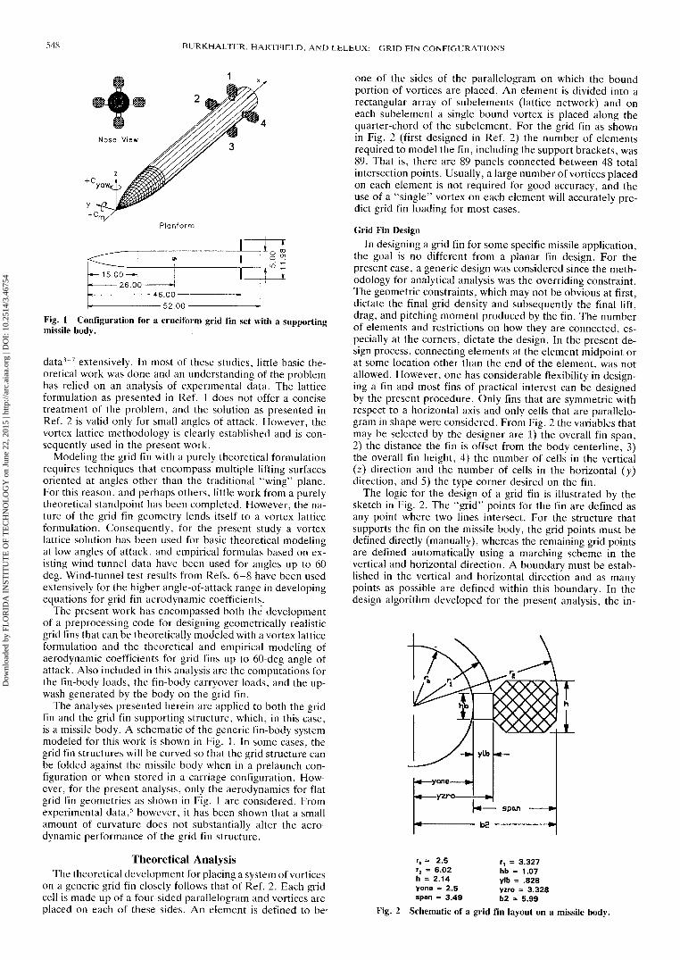
figurations,1 they are still considered an unconventional liftingsurface. Theoretical developments have lagged in the usageof these devices and, to date, much of the internal flowfieldassociated with the grid elements is still unknown. Figure 1provides a three-dimensional view of a typical grid fin appli-cation and pictures the grid elements lattice network inside arigid outer boundary. The attractiveness of a grid fin over aconventional fin is based on the fact that grid fins do not"stall" in the conventional sense, but continue to produce lifteven at very high angles of attack, and the fact that the hingemoments (actuator requirements) are extremely low becauseof the small chord length. The fundamental problem, in thepresent study, was to develop the theoretical methodology topredict the aerodynamic forces and moments produced by thegrid fin lifting surface as it is attached to a missile body asshown in Fig. 1.
For subsonic flow, efforts to model and understand thegrid fin have centered around a vortex lattice formulation1-2
and many published techniques have utilized experimental
547
Dow
nloa
ded
by F
LO
RID
A I
NST
ITU
TE
OF
TE
CH
NO
LO
GY
on
June
22,
201
5 | h
ttp://
arc.
aiaa
.org
| D
OI:
10.
2514
/3.4
6754
548 BURKHALTER, HARTFIELD, AND LELEUX: GRID FIN CONFIGURATIONS
Planform
15.00-*!26.00
-46.00-2.00-
Fig. 1 Configuration for a cruciform grid fin set with a supportingmissile body.
data3"7 extensively. In most of these studies, little basic the-oretical work was done and an understanding of the problemhas relied on an analysis of experimental data. The latticeformulation as presented in Ref. 1 does not offer a concisetreatment of the problem, and the solution as presented inRef. 2 is valid only for small angles of attack. However, thevortex lattice methodology is clearly established and is con-sequently used in the present work.
Modeling the grid fin with a purely theoretical formulationrequires techniques that encompass multiple lifting surfacesoriented at angles other than the traditional "wing" plane.For this reason, and perhaps others, little work from a purelytheoretical standpoint has been completed. However, the na-ture of the grid fin geometry lends itself to a vortex latticeformulation. Consequently, for the present study a vortexlattice solution has been used for basic theoretical modelingat low angles of attack, and empirical formulas based on ex-isting wind-tunnel data have been used for angles up to 60deg. Wind-tunnel test results from Refs. 6-8 have been usedextensively for the higher angle-of-attack range in developingequations for grid fin aerodynamic coefficients.
The present work has encompassed both the developmentof a preprocessing code for designing geometrically realisticgrid fins that can be theoretically modeled with a vortex latticeformulation and the theoretical and empirical modeling ofaerodynamic coefficients for grid fins up to 60-deg angle ofattack. Also included in this analysis are the computations forthe fin-body loads, the fin-body carryover loads, and the up-wash generated by the body on the grid fin.
The analyses presented herein are applied to both the gridfin and the grid fin supporting structure, which, in this case,is a missile body. A schematic of the generic fin-body systemmodeled for this work is shown in Fig. 1. In some cases, thegrid fin structures will be curved so that the grid structure canbe folded against the missile body when in a prelaunch con-figuration or when stored in a carriage configuration. How-ever, for the present analysis, only the aerodynamics for flatgrid fin geometries as shown in Fig. 1 are considered. Fromexperimental data,5 however, it has been shown that a smallamount of curvature does not substantially alter the aero-dynamic performance of the grid fin structure.
Theoretical AnalysisThe theoretical development for placing a system of vortices
on a generic grid fin closely follows that of Ref. 2. Each gridcell is made up of a four-sided parallelogram and vortices areplaced on each of these sides. An element is defined to be'
one of the sides of the parallelogram on which the boundportion of vortices are placed. An element is divided into arectangular array of subelements (lattice network) and oneach subelement a single bound vortex is placed along thequarter-chord of the subelement. For the grid fin as shownin Fig. 2 (first designed in Ref. 2) the number of elementsrequired to model the fin, including the support brackets, was89. That is, there are 89 panels connected between 48 totalintersection points. Usually, a large number of vortices placedon each element is not required for good accuracy, and theuse of a "single" vortex on each element will accurately pre-dict grid fin loading for most cases.
Grid Fin DesignIn designing a grid fin for some specific missile application,
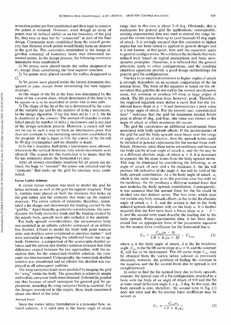
the goal is no different from a planar fin design. For thepresent case, a generic design was considered since the meth-odology for analytical analysis was the overriding constraint.The geometric constraints, which may not be obvious at first,dictate the final grid density and subsequently the final lift,drag, and pitching moment produced by the fin. The numberof elements and restrictions on how they are connected, es-pecially at the corners, dictate the design. In the present de-sign process, connecting elements at the element midpoint orat some location other than the end of the element, was notallowed. However, one has considerable flexibility in design-ing a fin and most fins of practical interest can be designedby the present procedure. Only fins that are symmetric withrespect to a horizontal axis and only cells that are parallelo-gram in shape were considered. From Fig. 2 the variables thatmay be selected by the designer are 1) the overall fin span,2) the distance the fin is offset from the body centerline, 3)the overall fin height, 4) the number of cells in the vertical(z) direction and the number of cells in the horizontal (y)direction, and 5) the type corner desired on the fin.
The logic for the design of a grid fin is illustrated by thesketch in Fig. 2. The "grid" points for the fin are defined asany point where two lines intersect. For the structure thatsupports the fin on the missile body, the grid points must bedefined directly (manually), whereas the remaining grid pointsare defined automatically using a marching scheme in thevertical and horizontal direction. A boundary must be estab-lished in the vertical and horizontal direction and as manypoints as possible are defined within this boundary. In thedesign algorithm developed for the present analysis, the in-
rb = 2.5r2 = 6.02h = 2.14yone = 2.5span = 3.49
r, = 3.327hb = 1.07ylb = .828yzro = 3.328b2 = 5.99
Fig. 2 Schematic of a grid fin layout on a missile body.
Dow
nloa
ded
by F
LO
RID
A I
NST
ITU
TE
OF
TE
CH
NO
LO
GY
on
June
22,
201
5 | h
ttp://
arc.
aiaa
.org
| D
OI:
10.
2514
/3.4
6754
BURKHALTER, HARTFIELD, AND LELEUX: GRID FIN CONFIGURATIONS 549
tersection points are first established and then logic to connectthe points is initiated. However, even though an array ofpoints may be defined within or on the boundary of the gridfin, they may or may not be "connected" as part of the finaldesign. Constraints were established from the overall geom-etry that dictated which points would finally form an elementin the grid fin. The constraints established in the design al-gorithm consisted of boundary limits that eliminated un-wanted points. In the design process, the following constraintlimitations were established:
1) No points were placed inside the radius designated asrl, except those constituting the base support structure.
2) No points were placed outside the radius designated asr2.
3) No points were placed inside the lateral dimension des-ignated as yzro, except those constituting the base supportstructure.
4) The shape of the fin at the base was determined by thevalue of the variable ibase, which determines if the base is tobe square or is to be truncated to cover one or two cells.
5) The shape of the fin at the tip is determined by the valueof the variable itip and by the number of delta y increments.In the design algorithm, if itip has been set to 1 or 2, the finis chamfered at the corners. The amount of chamfer is estab-lished purely by number of delta y increments and is not partof the design selection process. However, a corner cell willnot be cut in such a way to form an intersection point thatdoes not conform to the remaining restrictions established inthe program. If itip is input as 0.0, the corner of the fin willbe 90 deg (rectangular) and no chamfer is made.
6) In the y direction, half-delta y increments were allowed,whereas in the vertical direction, only whole increments wereallowed. The reason for this restriction is to insure that thefin has symmetry about the horizontal (y) axis.
After all correct coordinate locations for all points are de-fined, the logic to "connect" the points was initiated and the"elements" that make up the grid fin structure were estab-lished.Vortex Lattice Solution
A vortex lattice solution was used to model the grid finlattice network as well as the grid fin support structure. Thatis, vortices were placed on both the elements that make upthe grid lattice and the elements that make up the supportstructure. The entire system of elements, therefore, consti-tuted a fin design and determined the loading carried by the"grid fin." Apart from the geometric considerations, the aero-dynamic fin-body carryover loads and the loading created bythe missile body upwash were also included in the analysis.
For body upwash considerations, the axisymmetric bodywas modeled as an infinite cylinder composed of an infiniteline doublet. Efforts to model the body with point sources/sinks and doublets were completed in previous studies2-3 andwere successful in computing the additional loads due to up-wash. However, a comparison of the source/sink-doublet so-lution and the infinite line doublet solution revealed that littledifference existed between the two approaches, with the ex-ception that, for the source/sink-doublet solution, the com-puter run time increased. Consequently, the source/sink-doubletsolution was abandoned and an infinite line doublet was em-ployed in all subsequent analyses.
The wing carryover loads were modeled by imaging the gridfin "wing" inside the body. The procedure is relatively simpleand realistic carryover loads were obtained. It should be pointedout that because of small semispans for general grid fin ap-plications, modeling the wing carryover loads is essential. Forthe designs considered in this report, these loads constitutedabout one-third of the total.Normal Force
Since the vortex lattice formulation is a potential flow, in-viscid solution, it is valid only in the linear angle of attack
range that in this case is about 5-8 deg. Obviously, this isinadequate for general grid fin applications; consequently,existing experimental data was used to extend the range be-yond the vortex lattice limit up to (and beyond) 45 deg angleof attack. It is strongly stressed that this extension to higherangles has not been tested or applied to generic designs andit is not known, at this point, how well the equations applyto general configurations. Nevertheless the methods that wereutilized were based on logical assumptions and basic aero-dynamic principles. Therefore, it is believed that the generalprinciples apply to other configurations, and the resultingempirical equations provide a good design methodology forgeneral grid fin configurations.
The key to an empirical extension to higher angles of attackis strongly dependent on an accurate computation of the finnormal force. The form of the equation is based on the ob-servation that grid fins do not stall in the normal aerodynamicsense, but continue to produce lift even at large angles ofattack. The lift production does, however, peak. Therefore,the required equation must define a curve that has the tra-ditional linear slope at a = 0 and demonstrates a peak valueat a large angle of attack. For the present case, experimentaldata5"7 indicates that the grid fin maximum normal forcespeak at about 45 deg, and thus, this value was chosen as theangle of attack at which maximum lift occurs.
The grid fin experiences an additional aerodynamic forceassociated with body upwash effects. If the aerodynamics ofthe grid fin and the body upwash were linear over the rangeof angles of attack of interest, then the upwash terms couldbe included in general expressions for the normal force coef-ficient. However, since these terms are nonlinear and becausethe body can be at one angle of attack a, and the fin may beat a different absolute angle of attack a + 5, it is necessaryto separate the fin alone terms from the body upwash terms.This may be illustrated by considering the following: at anangle of attack of zero and a fin incidence 8, the fin willproduce lift indicative of the angle 8, but will be void of thebody upwash contribution. At a fin-body angle of attack, a,which is the same value as in the previous case but with nofin incidence, the fin produces a different normal force thatnow includes the body upwash contribution. Consequently,it was assumed that the normal force for the fin could bedivided into two distinct terms. The first term, which doesnot include any body upwash effects, is due to the fin absoluteangle of attack a + 5, and the second is due to the bodyinduced upwash dependent only on the body a. It is furtherrequired that the first term have a linear slope at a + 8 =0, and the second term must describe the loading due to thebody upwash. From experimental data, it has been deter-mined that an appropriate form of the parametric equationfor the normal force coefficient for the horizontal fins is
CN 8)1.0 + + S)2 (1)
where a is the body angle of attack, 8 is the fin incidenceangle, CNa is the fin lift curve slope at a = 0, and the constantK{ still has to be determined. The lift curve slope CNa maybe obtained from the vortex lattice solution as previouslydiscussed, however, the problem of finding the constant inthe equation and the fin normal force due to upwash is notstraightforward.
In order to find the fin normal force due to body upwash,consider the special case of a fin configuration attached to abody with the body at an angle of attack of 0.0 and the finat some small deflection angle 6, e.g., 5 deg. In this case, thebody upwash is zero, therefore, the second term in Eq. (1)does not exist and the fin normal force coefficient may bewritten as
CN = 1.0 + K.a2A
(2)
Dow
nloa
ded
by F
LO
RID
A I
NST
ITU
TE
OF
TE
CH
NO
LO
GY
on
June
22,
201
5 | h
ttp://
arc.
aiaa
.org
| D
OI:
10.
2514
/3.4
6754
550 BURKHALTER, HARTFIELD, AND LELEUX: GRID FIN CONFIGURATIONS
where, in general, aA = a + 5, the absolute angle of attackof the fin. The vortex lattice solution would certainly applyfor this case since it clearly falls within the linear range. Nowconsider a second case, with the body/fin at the same absoluteangle of attack as before, but in this case let 8 be zero and a= 5 deg. At this small angle of attack, the vortex latticesolution still applies and the normal force coefficient may befound that includes the body upwash effects as generated byan infinite line doublet along the centerline of the body.
The difference between these two solutions for the normalforce must be due to the body upwash. Even though this"differencing" approach would be unnecessary for small an-gles of attack, it is necessary for angles above the linear range.For the general case of a body at angle of attack and fin atsome incidence angle, outside the linear range, it is then as-sumed that the body upwash contribution to fin normal forcedoes not change with fin incidence, but is dependent only onthe body a.
In order to evaluate the constant Kl in Eq. (1), the followingobservations were made from experimental data.
1) The fin normal force appears to reach a maximum at anabsolute angle of attack of about 45 deg.
2) At this angle, the fin alone normal force (exclusive ofany body upwash effects) may be determined by assumingthat the fin frontal area appears as a near solid block and thenormal force can be expressed as
sin(45)(2) (3)
Here (fb) is the "flow blockage area" and the (2) is for twofins (right and left). In the above equation, it has also beenassumed that the force coefficient is 1.0, which is quite rea-sonable for a "near" solid block. In coefficient form, Eq. (3)becomes
(4)
If Eq. (4) is substituted into Eq. (2), then K may be deter-mined as
K = - CN45]/(7r2CN45) (5)
Now if the vortex lattice solution is obtained, turning the bodyupwash on, then the constant K in Eq. (2) may be found usingEq. (5) with the resulting normal force coefficient designatedas CN.on. If the process is repeated with the upwash turnedoff, then the normal force coefficient is designated as CN.off.The difference between these two cases, as previously dis-cussed, is the fin normal force due to the upwash created bythe body on the fins and must be equal to the second termin Eq. (1). That is
dif - 1.0 + Ko 1.0 (6)
From experimental data, this method of determining the bodyupwash contribution to the fin normal force in the nonlinearalpha range appears to be adequate at least for body anglesof attack up to 20 deg, but for body angles of attack above20 deg, the method is unproven.
In summary, the computational procedure for determiningthe fin normal force is as follows:
1) Given, a body a, a 5, and the geometry of the fin tocompute//?. The absolute angle of attack for the fin is aA =a + d.
2) Initially set the "angle of attack" to 5.0 deg and use thevortex lattice code alone to determine CNa_on for the casewhere the body is present.
3) Repeat the process, but delete the body from the com-putations and determine a value of CNa.of{.
4) Determine CN45 from Eq. (4).5) Compute Kon from Eq. (5), using the value of CNa.on
found in 1 above.6) Compute K0{{ from Eq. (5), using the value of CNa.off
found in 2 above.7) At each angle of attack and fin deflection angle, deter-
mine the upwash coefficient from Eq. (6). Find the fin normalforce coefficient from Eq. (1) in which K{ is the same as Kof{.
Fin MomentsThe horizontal fins produce moments about the hinge line
that are very small and are computed partially from the vortexlattice solution and partially from empirical factors. The mo-ments about the fin leading edge are computed by integratingsectional properties along the span for an initial angle of attackof 5.0 deg. These moments about the leading edge are thentransferred to the hinge line for evaluation of the fin hingemoments. At higher angles of attack, the value of the momentabout the leading edge is approximated by multiplying thevalue at 5 deg by the ratio of the respective normal forces.Consequently, the hinge moments for the fin become
C,,,hx = C,,,7[C/(2.0Lref)] (7)
where Cnf is the vortex lattice normal force coefficient at 5deg and C,, is the actual nonlinear fin normal force coefficientas computed from Eq. (1). Equation (7) may be derived byassuming that the c.p. on the fin chord does not change athigher angles of attack, and by observing that the fin chordis centered over the hinge line. Actually, the c.p. does shiftaft at higher angles of attack, but the chord is very small andthe chordwise shift is small. The root chord bending momentsare computed in a similar fashion as
Crcbm = Crcbm(y}(CnfflCnf) (&)
and finally, the moment about the configuration moment cen-ter is
(9)
Axial ForceThe axial force on the fin (drag at a = 0.0) is assumed to
be composed of skin friction, pressure drag, and an interfer-ence drag due to fin element intersections. For the skin fric-tion drag, the fin wetted area is computed and converted toan equivalent "flat plate" with an assumed laminar and/orturbulent boundary layer. The skin friction coefficient, as afunction of Reynolds number, is determined and finally afriction axial force coefficient is computed as Cdow. Thesecomputations for viscous axial force follow closely those inRef. 8. It is assumed that the pressure drag takes the formof
pressure dragcv=() = ^.(frontal area) (10)
In coefficient form, this results in
Cdp = (S^j)/(Srefcr) (11)
Finally, the element intersections create a drag that is em-pirically determined from experimental data5"7 as
Ctlxp = 2.0 x 0.000547 x (np + 2) (12)
where (np + 2) is the total number of grid intersection pointsincluding points on the base support structure. The axial forcecoefficient is then the sum of these three components:
ax = Cdow + Cdxp + Cdp (13)
Dow
nloa
ded
by F
LO
RID
A I
NST
ITU
TE
OF
TE
CH
NO
LO
GY
on
June
22,
201
5 | h
ttp://
arc.
aiaa
.org
| D
OI:
10.
2514
/3.4
6754
BURKHALTER, HARTFIELD, AND LELEUX: GRID FIN CONFIGURATIONS 551
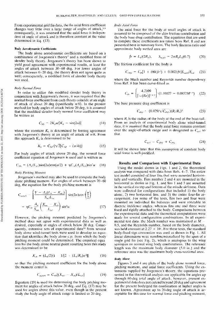
From experimental grid fin data, the fin axial force coefficientchanges very little over a large range of angles of attack,5-6
consequently, it was assumed that the axial force is indepen-dent of angle of attack and is therefore constant at the valuedetermined in Eq. (13).
Body Aerodynamic CoefficientsThe body alone aerodynamic coefficients are based on a
combination of Jorgensen's theory9 and a modified form ofslender body theory. Jorgensen's theory has been shown toyield good agreement with experimental results, at least forangles of attack between 30-60 deg. For lower angles ofattack between 0-20 deg, the theory does not agree quite aswell; consequently, a modified form of slender body theorywas used.
Body Normal ForceIn order to utilize this modified slender body theory in
conjunction with Jorgensen's theory, it was required that thenormal force coefficient from each theory coincide at an angleof attack of about 20 deg (specifically 77/8). In the presentmethod for body angles of attack below 20 deg, it is assumedthat the modified slender body normal force coefficient maybe written as
CNb = 2Khal[Kh - sin(2a)] (14)
where the constant Kb is determined by forcing agreementwith Jorgensen's theory at an angle of attack of 77/8. Fromthis approach Kh is determined to be
J - (rr/4)]} (15)
For body angles of attack above 20 deg, the normal forcecoefficient equation of Jorgensen is used and is written as
CNb = (X6/Sref)sin(2a)cos(o/2) 2a (16)
Body Pitching MomentJorgensen's method may also be used to compute the body
alone pitching moment. For angles of attack between 20-60deg, the equation for the body pitching moment is
[V - Ah(Lb - Xmc)\ . ^ , (aCm,,,*, = ———-^—^————— sm(2a)cos I -
AP (Xmc ~ Xc~ -^ —— sm'a (17)
However, the pitching moment predicted by Jorgensen'smethod does not agree with experimental data as well asdesired, especially at angles of attack below 20 deg. Conse-quently, extensive sets of experimental data10 from severalbody alone wind-tunnel tests were used to develop an equa-tion that identifies the body alone c.p. from which the bodypitching moment could be determined. The empirical equa-tion for the body alone neutral point resulting from this studywas determined to be
Xfh = (18)
so that the pitching moment coefficient for the body aboutthe moment center is
= CNb[(Xme - Xch)/Lrcf] (19)
Equation (19) is used for determining the body pitching mo-ment for angles of attack below 20 deg, and Eq. (17) may beused for angles above this value, even though in the presentstudy the body angle of attack range is limited to 20 deg.
Body Axial ForceThe axial force for the body at small angles of attack is
assumed to be composed of the skin friction contribution andthe body base drag contribution. The equations that are usedto compute these coefficients are taken from Ref. 8 and arepresented here in summary form. The body fineness ratio andapproximate body wetted area are
fr = ZV(2/O, Swtb = 27r/?/7L,(0.7) (20)
The friction coefficient for the body is
Cdhfc = Cfh[l + (60//r3) + 0.0025/r]5wct./5ref (21)
where the Mach number and Reynolds number dependencyfrom Ref. 8 has been curve-fitted as
The base pressure drag coefficient is
Cdbp = (23)
where R, is the radius of the body at the end of the boat-tail.From an analysis of experimental body alone wind-tunneldata, it is assumed that the body axial force remains constantover the angle-of-attack range and is designated as Caxb sothat
C — C + C (?4">^ax/j ~~ ^dbfc ^ ^dbp \^)
It will be shown later that this assumption of constant bodyaxial force is well-justified.
Results and Comparison with Experimental DataUsing the model shown in Figs. 1 and 2, the theoretical
analysis was compared with data from Refs. 4-7. The entiretest model consisted of four fins that were mounted horizon-tally and vertically. Fins number 2 and 4 are mounted in thehorizontal as shown in Fig. 1, and fins 1 and 3 are mountedin the vertical on top and bottom of the missile airframe. Datawere collected for configurations that included 1) the bodyalone, 2) two horizontal fins, and 3) the entire four-fin ar-rangement. For some of the tests, fins two and four weremounted on individual fin balances and were rotatable todiscrete incidence angles, whereas fins one and three werefixed and rigidly attached to the body. Comparisons betweenthe experimental data and the theoretical computations weremade for several configuration combinations. In all experi-mental test data, the Mach number was maintained at M =0.5, and the Reynolds number, based on the body diameter,was held constant at 2.27 x 10⁷. For these tests, the standardbody-fixed sign convention was used as shown in Fig. 1. Alllinear dimensions were nondimensionalized by the span of asingle grid fin (see Fig. 2), which is analogous to the wingsemispan on normal wing body combinations. The referencelength was the maximum body diameter (5.0 in.) and thereference area was the maximum body cross-sectional area.
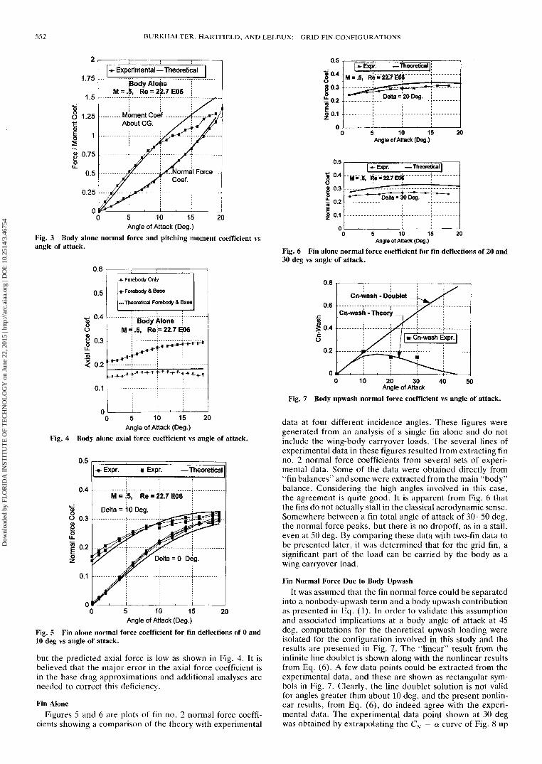
Body AloneFigures 3 and 4 are plots of the body alone normal force,
pitching moment, and axial force coefficients. Using the ex-tensions supplied by Jorgensen's theory, the equations pre-sented in the theoretical analysis are applicable for angles upthrough 60-deg total angle of attack, however, present ex-perimental data does not extend beyond 20 deg and agreementfor the present body/grid fin combination at higher angles isnot known. Agreement up to 20-deg angle of attack is ac-ceptable for this case for normal force and pitching moment,
Dow
nloa
ded
by F
LO
RID
A I
NST
ITU
TE
OF
TE
CH
NO
LO
GY
on
June
22,
201
5 | h
ttp://
arc.
aiaa
.org
| D
OI:
10.
2514
/3.4
6754
552 BURKHALTER, HARTFIELD, AND LELEUX: GRID FIN CONFIGURATIONS
Body Alone= .5, Re = 22.7E06
0 5 10 15 20Angle of Attack (Deg.)
Fig. 3 Body alone normal force and pitching moment coefficient vsangle of attack.
0.6
0.5
0.4
0.3
0.2
0.1
-n
-M
4- Forebody Only
-§- Forebody & Base
—Theoretical Forebody & Base
i Body Alone :M = .5, Re = 22.7 EOS
^*-^^-*~*~^^*-^
, i :
n-i
-M
0 5 10 15 20Angle of Attack (Deg.)
Fig. 4 Body alone axial force coefficient vs angle of attack.
-«- Expr. -»- Expr. — Theoretical
5 10 15Angle of Attack (Deg.)
20
Fig. 5 Fin alone normal force coefficient for fin deflections of 0 and10 deg vs angle of attack.
but the predicted axial force is low as shown in Fig. 4. It isbelieved that the major error in the axial force coefficient isin the base drag approximations and additional analyses areneeded to correct this deficiency.
Fin AloneFigures 5 and 6 are plots of fin no. 2 normal force coeffi-
cients showing a comparison of the theory with experimental
0.4
0.3
0.2
n
l*Exp
M«.5, R
.-=*=
r. — Theoretical |
i-22.7E08
Delta = 20 Deg.
s 10 15Angle of Attack (Deg.)
20
Nor
mal
For
ce C
oef.
0
0
0
0
C0 -
* N>
W
A
, G
I^Expr. — Theoretical |
rii"*"ite-ttyw"""'"___ — „.,.. r ..__„....--- - . . . . . .•~~~~ Delta = 30 Deg.
5 10 15 20Angle of Attack (Deg.)
Fig. 6 Fin alone normal force coefficient for fin deflections of 20 and30 deg vs angle of attack.
0 10 20 30 40 50Angle of Attack
Fig. 7 Body up wash normal force coefficient vs angle of attack.
data at four different incidence angles. These figures weregenerated from an analysis of a single fin alone and do notinclude the wing-body carryover loads. The several lines ofexperimental data in these figures resulted from extracting finno. 2 normal force coefficients from several sets of experi-mental data. Some of the data were obtained directly from"fin balances'1 and some were extracted from the main "body"balance. Considering the high angles involved in this case,the agreement is quite good. It is apparent from Fig. 6 thatthe fins do not actually stall in the classical aerodynamic sense.Somewhere between a fin total angle of attack of 30-50 deg,the normal force peaks, but there is no dropoff, as in a stall,even at 50 deg. By comparing these data with two-fin data tobe presented later, it was determined that for the grid fin, asignificant part of the load can be carried by the body as awing carryover load.
Fin Normal Force Due to Body UpwashIt was assumed that the fin normal force could be separated
into a nonbody-upwash term and a body upwash contributionas presented in Eq. (1). In order to validate this assumptionand associated implications at a body angle of attack at 45deg, computations for the theoretical upwash loading wereisolated for the configuration involved in this study and theresults are presented in Fig. 7. The "linear" result from theinfinite line doublet is shown along with the nonlinear resultsfrom Eq. (6). A few data points could be extracted from theexperimental data, and these are shown as rectangular sym-bols in Fig. 7. Clearly, the line doublet solution is not validfor angles greater than about 10 deg, and the present nonlin-ear results, from Eq. (6), do indeed agree with the experi-mental data. The experimental data point shown at 30 degwas obtained by extrapolating the CN - a curve of Fig. 8 up
Dow
nloa
ded
by F
LO
RID
A I
NST
ITU
TE
OF
TE
CH
NO
LO
GY
on
June
22,
201
5 | h
ttp://
arc.
aiaa
.org
| D
OI:
10.
2514
/3.4
6754
BURKHALTER, HARTFIELD, AND LELEUX: GRID FIN CONFIGURATIONS 553
to 30-deg angle of attack, and consequently, its accuracy issuspect. Clearly, the results agree quite well with the sparseexperimental data, at least up to about 20 deg, but extrapo-lation beyond this range requires further analysis.
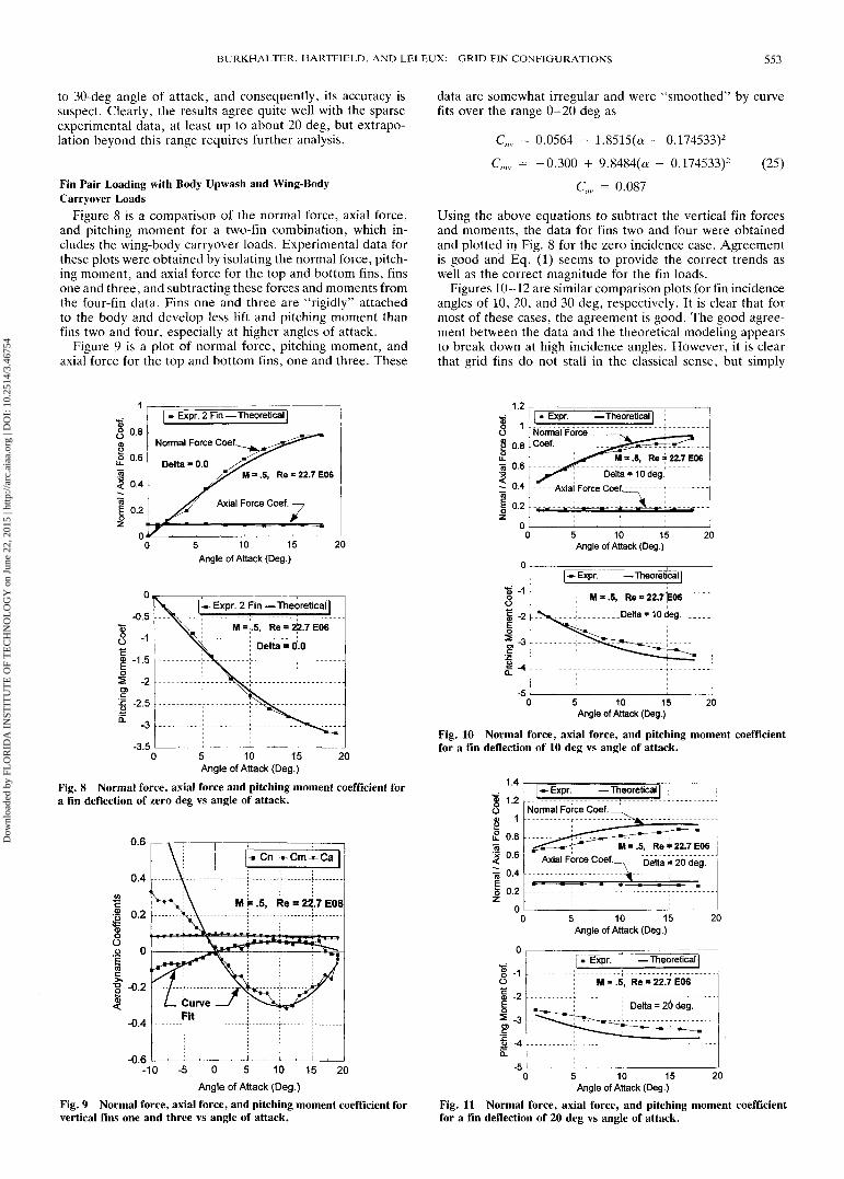
Fin Pair Loading with Body Upwash and Wing-BodyCarryover Loads
Figure 8 is a comparison of the normal force, axial force,and pitching moment for a two-fin combination, which in-cludes the wing-body carryover loads. Experimental data forthese plots were obtained by isolating the normal force, pitch-ing moment, and axial force for the top and bottom fins, finsone and three, and subtracting these forces and moments fromthe four-fin data. Fins one and three are "rigidly" attachedto the body and develop less lift and pitching moment thanfins two and four, especially at higher angles of attack.
Figure 9 is a plot of normal force, pitching moment, andaxial force for the top and bottom fins, one and three. These
data are somewhat irregular and were "smoothed" by curvefits over the range 0-20 deg as
Cnv = 0.0564 - 1.8515O - 0.174533)2
Cmv = -0.300 + 9.8484(a - 0.174533)2 (25)
Cav = 0.087
Using the above equations to subtract the vertical fin forcesand moments, the data for fins two and four were obtainedand plotted in Fig. 8 for the zero incidence case. Agreementis good and Eq. (1) seems to provide the correct trends aswell as the correct magnitude for the fin loads.
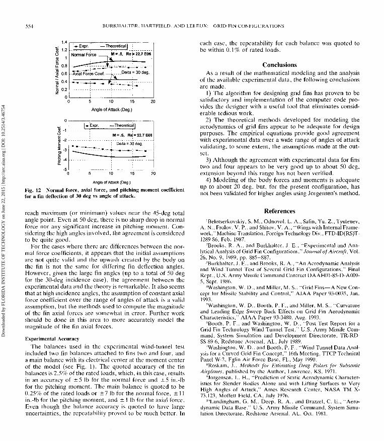
Figures 10-12 are similar comparison plots for fin incidenceangles of 10, 20, and 30 deg, respectively. It is clear that formost of these cases, the agreement is good. The good agree-ment between the data and the theoretical modeling appearsto break down at high incidence angles. However, it is clearthat grid fins do not stall in the classical sense, but simply
0.8
0.6
0.4
0.2
0
* Expr. 2 Fin —Theoretical]
Normal Force Coef.
Delta = 0.05, Re = 22.7E06
Axial Force Coef.75 10 15Angle of Attack (Deg.)
20
5 10 15Angle of Attack (Deg.)
20
Fig. 8 Normal force, axial force and pitching moment coefficient fora fin deflection of zero deg vs angle of attack.
-0.6-10 - 5 0 5 10 15 20
Angle of Attack (Deg.)Fig. 9 Normal force, axial force, and pitching moment coefficient forvertical fins one and three vs angle of attack.
1.2
1
0.8
0.6
0.4
0.2
^-Expr. —Theoretical |
Delta = 10 deg- - - - -Axial Force Coef.
5 10 15Angle of Attack (Deg.)
20
~Expr. -Theoretical |
M"= ~5, "Re = 22.7^66
5 10 15Angle of Attack (Deg.)
20
Fig. 10 Normal force, axial force, and pitching moment coefficientfor a fin deflection of 10 deg vs angle of attack.
1.4
H 1-2
£ 0.8
| 0.6
5 o-4
I 0.2
1-2
-3
I* Expr. -Theoretical |
Normal Force Coef.
" Axial Force Coef. eta 20 deg.
5 10 15Angle of Attack (Deg.)
20
-*- Expr. —Theoretical!
Re = 22.7E06
; Delta = 26 deg.
5 10 15Angle of Attack (Deg.)
20
Fig. 11 Normal force, axial force, and pitching moment coefficientfor a fin deflection of 20 deg vs angle of attack.
Dow
nloa
ded
by F
LO
RID
A I
NST
ITU
TE
OF
TE
CH
NO
LO
GY
on
June
22,
201
5 | h
ttp://
arc.
aiaa
.org
| D
OI:
10.
2514
/3.4
6754
554 BURKHALTER, HARTFIELD, AND LELEUX: GRID FIN CONFIGURATIONS
I 1-2
o
•| 0.6
5 o-4
|0.2
00
*Expr. — Theoretical] ;
Normal Force __ . M * .S, Re 1 22.7 E06
" *=± .-"-- •• r lii il ^ ^ • r '• - - - a- - -
- -A^iaTFc^ceCoef. — 1 - - -Delta = 30 de9-
^-^T*-^^-^— -^
5 10 15 2(
Angle of Attack (Deg.)
-2
-3
-s
* Expr. — Theoretical |
•-- ——— m~
"*•*- —— -.•rrr.— ,
- - -, - -M = .5, Re = 22.7E06
Delta = 30 deg.
10
Angle of Attack (Deg.)
Fig. 12 Normal force, axial force, and pitching moment coefficientfor a fin deflection of 30 deg vs angle of attack.
each case, the repeatability for each balance was quoted tobe within 0.1% of rated loads.
ConclusionsAs a result of the mathematical modeling and the analysis
of the available experimental data, the following conclusionsare made.
1) The algorithm for designing grid fins has proven to besatisfactory and implementation of the computer code pro-vides the designer with a useful tool that eliminates consid-erable tedious work.
2) The theoretical methods developed for modeling theaerodynamics of grid fins appear to be adequate for designpurposes. The empirical equations provide good agreementwith experimental data over a wide range of angles of attackvalidating, to some extent, the assumptions made at the out-set.
3) Although the agreement with experimental data for finstwo and four appears to be very good up to about 50 deg,extension beyond this range has not been verified.
4) Modeling of the body forces and moments is adequateup to about 20 deg, but, for the present configuration, hasnot been validated for higher angles using Jorgensen's method.
reach maximum (or minimum) values near the 45-deg totalangle point. Even at 50 deg, there is no sharp drop in normalforce nor any significant increase in pitching moment. Con-sidering the high angles involved, the agreement is consideredto be quite good.
For the cases where there are differences between the nor-mal force coefficients, it appears that the initial assumptionsare not quite valid and the upwash created by the body onthe fin is not the same for differing fin deflection angles.However, given the large fin angles (up to a total of 50 degfor the 30-deg incidence case), the agreement between theexperimental data and the theory is remarkable. It also seemsthat at high incidence angles, the assumption of constant axialforce coefficient over the range of angles of attack is a validassumption, but the methods used to compute the magnitudeof the fin axial forces are somewhat in error. Further workshould be done in this area to more accurately model themagnitude of the fin axial forces.
Experimental AccuracyThe balances used in the experimental wind-tunnel test
included two fin balances attached to fins two and four, anda main balance with its electrical center at the moment centerof the model (see Fig. 1). The quoted accuracy of the finbalances is 2.5% of the rated loads, which, in this case, resultsin an accuracy of ±5 Ib for the normal force and ±5 in.-lbfor the pitching moment. The main balance is quoted to be0.25% of the rated loads or ±7 Ib for the normal force, ±11in.-lb for the pitching moment, and ± 1 Ib for the axial force.Even though the balance accuracy is quoted to have largeuncertainties, the repeatability proved to be much better. In
References'Belotserkovskiy, S. M., Odnovol, L. A., Safin, Yu. Z., Tyulenev,
A. N., Frolov, V. P., and Shitov, V. A., "Wings with Internal Frame-work," Machine Translation, Foreign Technology Div., FTD-ID(RS)T-1289-86, Feb. 1987.
2Brooks, R. A., and Burkhalter, J. E., "Experimental and Ana-lytical Analysis of Grid Fin Configurations," Journal of Aircraft, Vol.26, No. 9, 1989, pp. 885-887.
3Burkhalter, J. E., and Brooks, R. A., "An Aerodynamic Analysisand Wind Tunnel Test of Several Grid Fin Configurations," FinalRept., U.S. Army Missile Command Contract DAAH01-85-D-A009-5, Sept. 1986.
Washington, W. D., and Miller, M. S., "Grid Fins—A New Con-cept for Missile Stability and Control," AIAA Paper 93-0035, Jan.1993.
'Washington, W. D., Booth, P. F., and Miller, M. S., "Curvatureand Leading Edge Sweep Back Effects on Grid Fin AerodynamicCharacteristics," AIAA Paper 93-3480, Aug. 1993.
6Booth, P. F., and Washington, W. D., "Post Test Report for aGrid Fin Technology Wind Tunnel Test," U.S. Army Missile Com-mand, System Simulation and Development Directorate, TR-RD-SS-89-6, Redstone Arsenal, AL, July 1989.
"Washington, W. D., and Booth, P. F., "Wind Tunnel Data Anal-ysis for a Curved Grid Fin Concept," 16th Meeting, TTCP TechnicalPanel W-2, Eglin Air Force Base, FL, May 1990.
lSRoskam, J., Methods for Estimating Drag Polars for SubsonicAirplanes, published by the Author, Lawrence, KS, 1971.
9Jorgensen, L. H., "Prediction of Static Aerodynamic Character-istics for Slender Bodies Alone and with Lifting Surfaces to VeryHigh Angles of Attack," Ames Research Center, NASA TM X-73,123, Moffett Field, CA, July 1976.
'"Landingham, G. M., Deep, R. A., and Brazzel, C. E., "Aero-dynamic Data Base," U.S. Army Missile Command, System Simu-lation Directorate, Redstone Arsenal, AL, Oct. 1981.
Dow
nloa
ded
by F
LO
RID
A I
NST
ITU
TE
OF
TE
CH
NO
LO
GY
on
June
22,
201
5 | h
ttp://
arc.
aiaa
.org
| D
OI:
10.
2514
/3.4
6754