non invasive, multi-length scale characterization of...
TRANSCRIPT

ICMAT 2007, July 2 to 5, 2007 Singapore
Non Invasive, Multi-length Scale Characterization of Smart Materials, Membranes, Sensors with a novel high resolution and high contrast CT
S H Lau, Andrei Tkachuk, Hauyee Chang, Fred Duewer, Hongtao Cui, Michael Feser, Wenbing Yun
Xradia Inc, 5052 Commercial Circle, Concord, CA, USA Email: [email protected]
Keywords: computed tomography, microXCT, nanoXCT, multilengthscale, non invasive imaging, smart materials, self healing materials, protective textile, protective armor, ballistic testing, FEA, fuel cell membranes, self healing composites, sensors, medical implants. Abstract. We describe a novel lab-based x-ray CT (computed tomography) system for rapid non invasive multi-length scale 3D characterization of internal structures of advanced and smart materials, from composites to sensors, from mm to sub 50 nm spatial resolution and with sample dimensions from several cm to microns. Notwithstanding most smart materials and sensors are in a matrix of low Z polymer or composites (making them challenging for x-ray radiography), the novel CT has excellent contrast. Several materials of interest to the military and home land security such as composites, polymers, micro and nano materials, protective materials against projectiles and blasting, smart self healing materials, fuel cell membranes and sensors and medical implants will be discussed. The key to this technology lies in proprietary x-ray optics, including Fresnel Zone plates and high resolution and high contrast detectors fabricated by Xradia.
Introduction
Smart materials that are able to be responsive to their environment, breathable fabric that can neutralize biological and chemical agents, self healing, light weight body armor, fuel cell membranes for portable power equipment, specialty micro and nanofibers are actively being developed for military, homeland security and industrial applications. While conventional imaging tools such as optical microscopy, electron microscopy and AFM are adequate to visualize surface structures, it has been difficult to accurately characterize their internal 3D arrays and functionalities. Typically, destructive sample preparation through physical, chemical cross section or etching must be performed to obtain full 3D volume information. This approach can be tedious and may introduce defects and artifacts, which may not even be present in the original specimen. Optical and confocal microscopy provide spatial resolution no better than 200 nm, limited by the diffraction limit of the visible light. While electron microscopy can achieve spatial resolution in the nm to A lengthscale, sample thickness requirement may not be always suitable and preparation can be very elaborate, including the need to be compatible with high vacuum and be electrically conductive. Besides, it is difficult to visualize internal 3D arrays and pores of materials based on 2D images alone. In this paper we shall describe a novel multilengthscale micro-nano x-ray computed tomography (CT) system for rapid non invasive 3D imaging of internal structures in a variety of materials, including lightweight and complaint textiles based protective systems, light weight armor, smart materials for self healing and multifunctional composites, fuel cell membranes and sensors, at imaging resolution from mm to sub 50 nm spatial resolution and without the need for elaborate and time consuming sample preparation steps, typical of electron microscopy. The system is also capable of imaging low Z materials such as polymers at high contrast. System supports specimen sizes ranging from several cm to microscopic dimensions
2
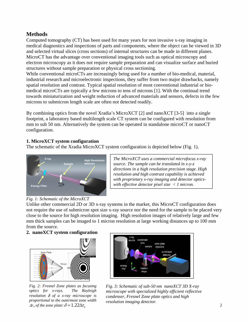
Methods Computed tomography (CT) has been used for many years for non invasive x-ray imaging in medical diagnostics and inspections of parts and components, where the object can be viewed in 3D and selected virtual slices (cross sections) of internal structures can be made in different planes. MicroCT has the advantage over conventional imaging tools such as optical microscopy and electron microscopy as it does not require sample preparation and can visualize surface and buried structures without sample preparation or physical cross sectioning. While conventional microCTs are increasingly being used for a number of bio-medical, material, industrial research and microelectronic inspections, they suffer from two major drawbacks, namely spatial resolution and contrast. Typical spatial resolution of most conventional industrial or bio-medical microCTs are typically a few microns to tens of microns [1]. With the continual trend towards miniaturization and weight reduction of advanced materials and sensors, defects in the few microns to submicron length scale are often not detected readily. By combining optics from the novel Xradia’s MicroXCT [2] and nanoXCT [3-5] into a single footprint, a laboratory based multilength scale CT system can be configured with resolution from mm to sub 50 nm. Alternatively the system can be operated in standalone microCT or nanoCT configuration. 1. MicroXCT system configuration The schematic of the Xradia MicroXCT system configuration is depicted below (Fig. 1).
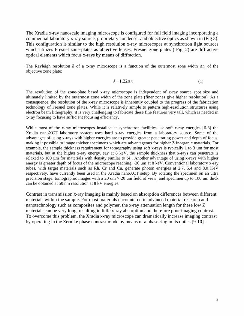
Fig. 1: Schematic of the MicroXCT Unlike other commercial 2D or 3D x-ray systems in the market, this MicroCT configuration does not require the use of submicron spot size x-ray source nor the need for the sample to be placed very close to the source for high resolution imaging. High resolution images of relatively large and few mm thick samples can be imaged to 1 micron resolution at large working distances up to 100 mm from the source. 2. nanoXCT system configuration
X-ray
Energy Filter
Sample High Resolutiondetector
Fig. 3: Schematic of sub-50 nm nanoXCT 3D X-ray microscope with specialized highly efficient reflective condenser, Fresnel Zone plate optics and high resolution imaging detector.
Fig. 2: Fresnel Zone plates as focusing optics for x-rays. The Rayleigh resolution δ of a x-ray microscope is proportional to the outermost zone width ∆rn of the zone plate:δ =1.22∆rn
The MicroXCT uses a commercial microfocus x-ray source. The sample can be translated in x-y-z directions in a high resolution precision stage. High resolution and high contrast capability is achieved with proprietary x-ray imaging and detector optics- with effective detector pixel size < 1 micron.
3
The Xradia x-ray nanoscale imaging microscope is configured for full field imaging incorporating a commercial laboratory x-ray source, proprietary condenser and objective optics as shown in (Fig 3). This configuration is similar to the high resolution x-ray microscopes at synchrotron light sources which utilizes Fresnel zone-plates as objective lenses. Fresnel zone plates ( Fig. 2) are diffractive optical elements which focus x-rays by means of diffraction. The Rayleigh resolution δ of a x-ray microscope is a function of the outermost zone width ∆rn of the objective zone plate: δ =1.22∆rn (1) The resolution of the zone-plate based x-ray microscope is independent of x-ray source spot size and ultimately limited by the outermost zone width of the zone plate (finer zones give higher resolution). As a consequence, the resolution of the x-ray microscope is inherently coupled to the progress of the fabrication technology of Fresnel zone plates. While it is relatively simple to pattern high-resolution structures using electron beam lithography, it is very challenging to fabricate these fine features very tall, which is needed in x-ray focusing to have sufficient focusing efficiency. While most of the x-ray microscopes installed at synchrotron facilities use soft x-ray energies [6-8] the Xradia nanoXCT laboratory system uses hard x-ray energies from a laboratory source. Some of the advantages of using x-rays with higher energies are to provide greater penetrating power and depth of focus, making it possible to image thicker specimens which are advantageous for higher Z inorganic materials. For example, the sample thickness requirement for tomography using soft x-rays is typically 1 to 3 µm for most materials, but at the higher x-ray energy, say at 8 keV, the sample thickness that x-rays can penetrate is relaxed to 100 µm for materials with density similar to Si . Another advantage of using x-rays with higher energy is greater depth of focus of the microscope reaching ~30 um at 8 keV. Conventional laboratory x-ray tubes, with target materials such as Rh, Cr and Cu, generate photon energies at 2.7, 5.4 and 8.0 KeV respectively, have currently been used in the Xradia nanoXCT setup. By rotating the specimen on an ultra precision stage, tomographic images with a 20 um × 20 um field of view, and specimen up to 100 um thick can be obtained at 50 nm resolution at 8 kV energies. Contrast in transmission x-ray imaging is mainly based on absorption differences between different materials within the sample. For most materials encountered in advanced material research and nanotechnology such as composites and polymer, the x-ray attenuation length for these low Z materials can be very long, resulting in little x-ray absorption and therefore poor imaging contrast. To overcome this problem, the Xradia x-ray microscope can dramatically increase imaging contrast by operating in the Zernike phase contrast mode by means of a phase ring in its optics [9-10].

4
Results and Discussion
To demonstrate the capabilities of the novel multilengthscale CT, non invasive structural characterization of several classes of materials and sensors of interest to the military and homeland security will be described.
1. Textile Protection Materials
Compliant textile materials for protection had been used for thousands of years, from layers silk worn by the samurai in medieval Japan to commercial glass fibers and nylon in the recent past. However these materials are no longer effective against modern high velocity firearms. It is not until the late 1960’s when a new class of high stiffness and strength filaments ( based on the aramid material, Kevlar, and other high molecular weight polyethylene), that textile armor began to show promise. Improvements in the performance of these light weight textile based protective materials require innovative reinforcement and hybridization schemes. To date, the majority of ballistic textile development for ballistic vests, hard and soft armor is based on experiments and experience. Ballistic impacts onto textile fabrics present a challenging modeling environment, where contact, complex stress and strain states with severe gradients and frictions between filaments and yarns have to be taken into account. Although a number of analytical and computational models have been developed and yielded useful insight, to date, the ballistic performance of as manufactured textile is not well understood. Textile is fundamentally filaments which are arranged in bundles, called yarn, which are then arranged in some repeating format. Therefore any accurate simulation model must take into account a multiscale approach, from filament to fabric level. Such highly accurate advanced model is currently being pursued by the military with academia that will ultimately relate the constituent material, the filament to its textile architecture, manufacturing process and finally to its ballistic performance prediction. To help achieve this goal, it is imperative that accurate non invasive multilengthscale 3D characterization data of such textiles down to the filament level before and after ballistic testing be available. This requirement of providing experimental validation to the simulation model being developed can be readily met with the described novel CT.
In the feasibility study, we chose the new fabric produced by a hybridation scheme developed by Textech Industries, ME, USA which had showed much promise in ballistic testing with projectiles compared to conventional 2D fabric of the same denier. This hybrid textile is an array of different weave styles and non woven felts are combined along a needling process to create a novel through thickness reinforced 3D hybrid fabric ( Fig. 4 ). Research trying to understand the better performance is still ongoing, but it is believed that the needling and felting inhibit the tows and increases the number of fibers that interact with the projectile

5
Fig. 4. show a schematic of the hybrid material involving traditional weaves(1), felt(2) and needling(3) and corresponding CT slices of the fabric at 1 micron resolution in (a) 3D rendered image (b) CT slice at x-y plane, (c) CT slice at x-z plane and (d) CT slice at y-z plane. Details of its weave down to the individual filament fiber and orientation can be characterized. (Sample courtesy: Stan Farrell, Tex Tech Industries).
Fig. 5 and 6 are CT slices of fabric after ballistic impact at different resolution. By providing non invasively virtual cross sections at different planes at low to high resolution, including the characterization of residual metal fragments of projectile on the fabric, can provide experimental validation for advanced modeling techniques such as Digital Element Analysis (DEA) by Sun and Wang [11]. By taking a multiscale approach, more accurate prediction of new protective clothing designs when they are under projectile impact can be developed.
Fig. 5: CT slices of projectile impact on fabric. Note metal fragments residues are also detected
Fig. 6: CT slices of same fabric at higher resolution, showing details of individual filaments.
6
2. Armor Materials
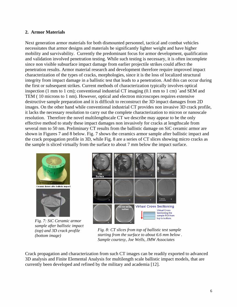
Next generation armor materials for both dismounted personnel, tactical and combat vehicles necessitates that armor designs and materials be significantly lighter weight and have higher mobility and survivability. Currently the predominant focus for armor development, qualification and validation involved penetration testing. While such testing is necessary, it is often incomplete since non visible subsurface impact damage from earlier projectile strikes could affect the penetration results. Armor material research and development therefore require improved impact characterization of the types of cracks, morphologies, since it is the loss of localized structural integrity from impact damage in a ballistic test that leads to a penetration. And this can occur during the first or subsequent strikes. Current methods of characterization typically involves optical inspection (1 mm to 1 cm); conventional industrial CT imaging (0.1 mm to 1 cm) `and SEM and TEM ( 10 microns to 1 nm). However, optical and electron microscopes requires extensive destructive sample preparation and it is difficult to reconstruct the 3D impact damages from 2D images. On the other hand while conventional industrial CT provides non invasive 3D crack profile, it lacks the necessary resolution to carry out the complete characterization to micron or nanoscale resolution. Therefore the novel multilengthscale CT we describe may appear to be the only effective method to study these impact damages non invasively for cracks at lengthscale from several mm to 50 nm. Preliminary CT results from the ballistic damage on SiC ceramic armor are shown in Figures 7 and 8 below. Fig. 7 shows the ceramics armor sample after ballistic impact and the crack propagation profile in 3D, while Fig. 8 are a series of CT slices showing micro cracks as the sample is sliced virtually from the surface to about 7 mm below the impact surface.
Crack propagation and characterization from such CT images can be readily exported to advanced 3D analysis and Finite Elemental Analysis for multilength scale ballistic impact models, that are currently been developed and refined by the military and academia [12].
Fig. 7: SiC Ceramic armor sample after ballistic impact (top) and 3D crack profile (bottom image)
Fig. 8: CT slices from top of ballistic test sample starting from the surface to about 6.6 mm below . Sample courtesy, Joe Wells, JMW Associates

7
3. Smart Materials: Self Healing Composites
While a lot of progress has being made in lighter weight armor utilizing polymer-composite matrix materials, one major limitation which is still looming at large is the logistical requirements with repair and maintenance. Repair is typically carried out by removing and replacing large area of damaged composites affected by the damage. Low or high rate ballistic impacts can induce delamination and cracks that propagate over large regions, often far removed from the point of initial impact. This process of repair is time consuming, costly and often requires a highly skilled technician.
One approach to solve this issue is to make use of self healing and self morphing materials. In a landmark study by White, Sottos and associates at the University of Illinois [13], self healing properties can be engineered into a composite by incorporating urea-formaldehyde micro containing dicyclopentadiene (DCPD) liquid healing agent containing 10% wt% Grubbs’ catalyst, which serves as the polymerizing agent. The schematic on the self healing concept is illustrated in Fig. 9. When damage occurs the capsule ruptures and releases the healing agent and thereby polymerization takes place to repair the crack. This work and the “mendomer” developed by UCLA by Chen et al; [14] where the material can be repaired after repeated damage due to its thermally reversible highly crosslinked ionic polymers provided the basis of the new classes of self healing materials ( Fig. 10). However, all these materials are still in the early stage of research and they have shown tremendous promise to self heal after an impact damage.
Fig. 9: Optical Micrograph (a) and Schematic of Self healing Concept (b)
Fig 10 Schematic of self healing ionomers that are thermally reversible

8
An example of the use of the novel CT for nanoscale imaging for some of the next generation self healing capsules developed by Sottos and her group at the Beckman Institute, University of Illinois, Urbana Champaign is shown below.
4. Soldier worn and Man portable Fuel Cells
The soldier war fighting capabilities have increasingly been reliant on power sources for essential communication support, thermal weapon and night vision systems. For over a decade batteries have been the main power source. In line with the need to reduce the weight that are currently carried by a soldier from the up to 100 lbs to something more manageable, the need for lightweight, long life high density power sources is another area of great interest to the military. Moreover, with recent advances in Digital warfare, the modern soldier war fighting capabilities have exceeded the power requirements of what traditional batteries can provide. Therefore, it is not uncommon for soldiers to carry multiple batteries of various chemistries which also complicate the logistic supply chain. One promising candidate to replace traditional batteries is the use of fuel cell systems for soldier worn and the larger man-portable systems. Some of the advantages of Fuel cells are the much longer lifetime, high efficiency and low acoustic thermal signatures. While fuel cell membranes have made tremendous advances, research is still ongoing to understand the reasons why they fail and the role new materials and catalyst can play in improving efficiencies and lifetime. To help understand why fuel cell membrane fails, the novel non invasive CT can provide useful insights on the structural changes within the membrane at resolution from 1 micron using microCT mode to 50 nm with nanoCT mode (Fig.12 and 13). This analysis can be accomplished at the fraction of the time taken with traditional destructive SEM or TEM imaging, and without potential artifacts to the structures caused by electron microscopy sample preparation and charged particle (e beam) interaction with a non conductive polymeric membrane.
Fig.11. Self healing micro and nano capsules release a healing agent when ruptured, where it mixes with a chemical catalyst, and polymerization takes place which repairs the crack or delamination. Capsules imaged at 50 nm. Sample courtesy: Prof Nancy Sottos, Beckman Inst., Univ. Illinois, Urbana

9
5. Smart Materials, Medical Implants and Sensors
As outlined in the earlier fuel cell membrane example, this ability to examine structural changes in polymeric membranes non invasively at multilengthscale in 3D, can also be applied to a variety of smart materials. This includes membranes which are responsive to their environment, or breathable fabric that can neutralize biological and chemical agents, but are permeable to moisture [ 15] .
Another common denominator in smart materials and sensors is that materials are generally in a low Z matrix ( for example polymer based). Low Z materials pose a big problem to conventional x-ray imaging, because there is little x-ray attenuation for these soft or low density samples. The novel CT solves this problem utilizing Zenike phase contrast mode using phase rings when used in the nanoCT imaging mode or through its proprietary phase enhanced detector optics, when operated under microCT mode.
The next example (Fig. 14), demonstrates the high contrast imaging of an extreme low z material, such as Be disc (Atomic # 4) used as a coating in target spheres in inertial confinement fusion (ICF) and high energy density physics( HEDF) experiments.
Figure 12: Be disc, showing 1 micron size
Fig. 12: CT slices at different planes of unused membrane vs failed membrane and functional membrane at 1 micron resolution, showing distinct structural differences. Sample courtesy: Fernando Gazon, Los Alamos National Labs
Fig. 13: CT slices at 50 nm resolution reveals detailed structural changes across the membrane interface including the degree of redistribution of Pt catalyst.
Fig. 14. Laser drilled hole on Be shell on a laser fusion target sphere can be seen very clearly, despite the inherently poor x-ray contrast for such materials.

10
Sensors, medical implants and electronics are also of great interest to the military. This category of samples can likewise be easily imaged in the multilengthscale CT to determine failure mechanism and reliability issues. Example showing non destructive cross sectioning of a several mm thick pacemaker, a medical implant device is shown (Fig. 15).
Conclusion This paper discussed non invasive 3D structural characterization, failure mechanism and process development for a variety of materials and sensors, from ballistic impact damage assessment of fabric and armor materials to smart materials, functional membranes and sensors . The novel multilengthscale CT promised to be a powerful tool for non invasive characterization tool for a variety of materials and sensors that hold great interest to the military and homeland security. Acknowledgment The authors wish to thank Joanna Cheong and Tak Hong Tan of Xradia’s Application laboratory for their invaluable assistance in imaging the above samples.
References
[1] Diaz, R, et al.,: Assembly Analytical forum, Analytical Tool Roadmap, White Paper, International Sematech, Technology Transfer #04054532A-TR, ISTFA Workshop (2004)
[2] Scott, D, et al.,: High Resolution 3D Tomography for Advanced Package Failure Analysis, ISTFA Proceedings (2003)
[3] S. Wang, et al. “A transmission x-ray microscope (TXM) for nondestructive 3D imaging of IC’s at sub 100-nm Resolution”, ISTFA Proceedings (2002) [4] Tkachuk, A. et al., “ High Resolution x-ray tomography using laboratory sources”, Proc SPIE, Vol 6318, 63181D (2006)
[5] Lau, S.H et al., : ”Non destructive Failure analysis technique with a lab based nanotomography system”, Proceedings LSIT Symposium Osaka, Japan (2006)
[6] Attwood, D, “Nanotomography comes of age”, Nature 442, 642-643 ( 2006)
Fig. 15. Relatively large and thick electronic gadgets, such as a pacemaker, an implantable medical device, can be inspected non invasively for defects at high resolution

11
[7] Weilun Chao, Bruce D, Harteneck J, Alexander Liddle, Erik H, Anderson and David T. Attwood, “ Soft X-ray microscopy at a spatial resolution better than 15 nm”, Nature 435, 1210-1213 ( 2005) [8] K. W. Kim, Y. Kwon, K-Y. Nam, J-H. Lim, K-G. Kim et al., “Compact soft x-ray transmission microscopy with sub-50 nm spatial resolution”, Phys. Mol. Biol., 51, N99-N107 (2006) [9] Visible light Zernike phase contrast introduction: http://www.microscopyu.com/articles/phasecontrast/phasemicroscopy.html [10] F. Zernike. “Das Phasenkontrastverfahren bei der mikroskopischen Beobachtung". Zeitschrift für technische Physik, 36, 848-851 (1935) [11] Wang et al., „ Ballistic Penetration Simulation of Textile Fabrics”, Proceedings of the Fiber Society 2006 Fall Annual Meeting and Tech Conf.(2006) [12] Wells, J.M., “On incorporating XCT into Predictive Ballistic Impact Damage Modeling,” Proceedings of 22nd International Ballistics Symposium, ADPA, Vol 2, pp1223-1230 (2005) [13] White, S.R., et al.,: Autonomic Healing of Polymwer Composites, Nature, 409, 794-797 (2001) [14] Chen, X., et al., : A Thermally Remendable Cross-Linked Ploymeric Materials, Science, 295, 1698-1702 (2002) [15] Crawford, et al., “ Flexible Composite Membranes for Selective Permeability”, Proceedings, 25th Army Science Conference (2006).