non-destructive testing of the historic timber roof … · ods for timber structures include both...
TRANSCRIPT

NON-DESTRUCTIVE TESTING OF THE HISTORIC TIMBER ROOF
Downloaded from: https://research.chalmers.se, 2020-03-23 19:29 UTC
Citation for the original published paper (version of record):ERICSSON, K., KARAWAJCZYK, E., Kliger, R. et al (2018)NON-DESTRUCTIVE TESTING OF THE HISTORIC TIMBER ROOF STRUCTURES OF THE
N.B. When citing this work, cite the original published paper.
research.chalmers.se offers the possibility of retrieving research publications produced at Chalmers University of Technology.It covers all kind of research output: articles, dissertations, conference papers, reports etc. since 2004.research.chalmers.se is administrated and maintained by Chalmers Library
(article starts on next page)
© 2018 WIT Press, www.witpress.comISSN: 2058-8321 (paper format), ISSN: 2058-833X (online), http://www.witpress.com/journalsDOI: 10.2495/HA-V2-N2-218-229
NON-DESTRUCTIVE TESTING OF THE HISTORIC TIMBER ROOF STRUCTURES OF THE NATIONAL MUSEUM IN
STOCKHOLM, SWEDEN
KARIN ERICSSON1, EWA KARAWAJCZYK2, ROBERT KLIGER3, THOMAS LECHNER4,ELZBIETA LUKASZEWSKA5, WITOLD MISZTAL6, TOMASZ NOWAK7*
1SWECO AB, Sweden.2The National Property Board of Sweden, Sweden.
3Faculty of Civil and Environmental Engineering, Chalmers University, Sweden.4NCC Infrastructure, Sweden.
5Byggnadstekniska Byrån, Sweden.6,7Faculty of Civil Engineering, Wroclaw University of Technology, Poland.
ABSTRACTThe National Museum in Stockholm is Sweden’s leading museum of art and design. Behind the now closed doors of the National Museum and its construction coverings a renovation project is taking place, which began in 2014 and will be completed in 2018. The renovation project will create a modern museum, a brighter atmosphere for the arts and for its visitors. Part of the renovation project was to de-sign and upgrade the timber roof structure for new loads according to Eurocode 5. As the roof structure was originally built in 1860, it was important to evaluate the condition and mechanical properties of the original load-bearing timber members. The roof structure, which is of main interest, comprises roof trusses and lantern structures.
The main aim of the project regarding the timber roof structure in the National Museum was a safety verification in both the ultimate state (ULS) and the serviceability limit state (SLS). The preliminary capacity calculations for the roof structure showed that the roof members were under the new load conditions (with increased loads due to security and environmental requirements) utilized above 100%. Therefore, an investigation into the properties of the old timber members and connections was of vital importance. The need for non-destructive testing (NDT) of structural timber is well known under the name of strength grading and the concept has been used for many years to classify timber with respect to mechanical performance. The stress wave technique used in the project was based on commercial instruments such as FAKOPP®. The timber quality investigation for the attic roof structures showed that the material was generally in very good condition. As a result, according to SS-EN 338-2009, the timber strength could be assigned strength class C27–C30. Based on the results of the investigation, further design of strengthening works and refurbishment of the roof structure were being undertaken.Keywords: assessment timber structures, non-destructive test timber structures, renovation timber structures
1 INTRODUCTIONHistoric structures represent a part of the cultural heritage of every nation and societies pay considerable attention to their preservation and maintenance. Recently, cultural heritage has been considered to be an asset rather than a cost. In historic structures, it is important to preserve the original structure to the greatest possible extent. Much of the damage observed in historic timber structures can be attributed to biodegradation. The deterioration of struc-tural members results in changes in geometry and load-bearing capacity. Replacement of deteriorated members may not be an acceptable option for structures of historic significance and redesign may be necessary to sustain functionality of the structure. The preservation of historic structures presents many challenges ranging from social and economic issues to technical methods and solutions for condition assessment and verification. It is therefore of great importance to adopt structural health monitoring techniques to assess the remaining
Karin Ericsson et al., Int. J. of Herit. Archit., Vol. 2, No. 2 (2018) 218–229

Karin Ericsson et al., Int. J. of Herit. Archit., Vol. 2, No. 2 (2018) 219
load-bearing capacity for timber structures. Through reliable and appropriate assessment and monitoring of timber structures, it is possible to detect any weaknesses at an early stage and appropriate actions to extend the structures’ service life can be taken. Nowadays, safety requirements, eco-friendly, economic and cultural issues create an increasing necessity to maintain, preserve and refurbish existing historic timber structures. The structural strength assessment of timber structures uses diverse procedures and tools, which can assist special-ists in the evaluation of the structural condition and safety of timber structures in situations where the longevity is questionable because of visible deterioration, damaging events or change of use. The assessment of timber structures is based on a multidisciplinary approach aimed at providing information about the mechanical properties and actual condition of timber members and the mechanical behaviour of joints. This information is essential for a reliable structural safety analysis, which gives guidance to the conservation, replacement or strengthening work necessary to ensure an adequate safety level.
Part of the National Museum refurbishment project was to design and upgrade the timber roof structure for new loads according to Eurocode 5. As the roof structure was originally built in 1860, it was important to evaluate the condition and mechanical properties of the origi-nal load-bearing timber members and also the condition of the connections. The building is more than 150 years old and was built at Blasieholmen in Stockholm. Since 1935 the National Museum has been a national monument. The building is owned and managed by the National Property Board of Sweden. From the year 2013 to a few years ahead, the museum building will be closed to undergo extensive renovation and refurbishment. The building consists of three storeys with dimensions of length 87 meters, width 57 meters and height 30 meters. The plan is characterized by a central part with two wings enclosing their courtyard. The roof structure, which is of main interest, comprises roof trusses and lantern structures. In architecture, lanterns comprise a round or polygonal tural (turret) with windows, crowning a roof or a dome.
2 TYPOLOGY OF ROOF STRUCTURES IN NATIONAL MUSEUMFor the structural assessment calculations of two lanterns roof structures a numerical 3D model was prepared based on a 3D-CAD model (Figs 1 and 2). The roof structure no. 1 is presented in Fig. 3, while the roof structure no. 3 is presented in Fig. 5. A 2D numerical
NO. 1
NO. 2
NO. 3
Figure 1: The overview of the National Museum roof structures.

220 Karin Ericsson et al., Int. J. of Herit. Archit., Vol. 2, No. 2 (2018)
model for roof structure no. 2 was prepared based on 3D-CAD model (Figs 1, 2 and 4). In this chapter only these three types of roof structures are presented as the non-destructive test-ing of structural timber was performed only for those historical roof structures. Other roof structures (Figs 1 and 2) were strengthened and rebuilt without any further non-destructive testing of structural timber.
NO. 2
NO. 3
NO. 1
Figure 2: The overview of the National Museum roof structures.
Figure 3: The roof structure no. 1.

Karin Ericsson et al., Int. J. of Herit. Archit., Vol. 2, No. 2 (2018) 221
Figure 4: The roof structure no. 2.
Figure 5: The roof structure no. 3.

222 Karin Ericsson et al., Int. J. of Herit. Archit., Vol. 2, No. 2 (2018)
2.1 Roof structure type 1
The roof structure type 1 includes two transversal frames and one longitudinal frame carry-ing these two transversal frame structures (Fig. 3). The investigation campaign included a 3D scanning and detailed geometrical survey. Data collected during the investigation campaign were used for the preliminary analysis of the roof structure.
2.2 Roof structure type 2
The roof structure type 2 is called a king post truss with two principal rafters, a tie beam and a central vertical king post. Two different types of the king post trusses were built in the roof on the National Museum. The first type of trusses included two angled struts connected directly to the king post while the second type of trusses included two angled struts connected to tie beam (Fig. 4).
2.3 Roof structure type 3
The roof structure type 3 is similar in geometry to the roof structure type 1 and includes two transversal frames connected in apex with a ridge beam and two longitudinal rafters (Fig. 5).
The identification of the structural system of each of the roof structures aimed at under-standing the behaviour and the structural role of each component and each connection between elements and components and, eventually, verifying that the structural system works as a whole. Through a suitable assessment the most effective intervention as strengthening or redistribution of loads has been designed.
3 NON-DESTRUCTIVE AND QUASI-NON-DESTRUCTIVE TEST METHODSThe assessment of serviceability and safety of a timber structure and any subsequent inter-vention design requires an estimation of the relevant mechanical properties of the structural materials in use. In general, the so-called reference strength-grading properties (densit y, modulus of elasticity [MOE] and bending strength) have to be estimated for timber. Estimatio n of mechanical properties of wood is the most cumbersome task during on-site inspection of structures, given the imperfect correlation between most parameters estimated non-destructivel y and inferred mechanical properties. Therefore, different approaches are recommended: proof loading, visual strength-grading and non-destructive or semi-destructiv e measurement of properties [1]. Non-destructive and quasi-non-destructiv e test methods used in the project of National Museum are presented in this chapter.
3.1 Non-destructive test method – the stress wave method
The main aim of the project regarding the timber roof structure in the National Museum was a safety verification in both the ultimate state (ULS) and the serviceability limit state (SLS). The preliminary capacity calculations for the roof structure showed that the roof members were under the new load conditions (with increased loads due to security and environmental requirements) utilized above 100%, particularly in SLS design. Therefore, an investigation into the properties of the old timber members and connections was of vital importance. The need for non-destructive testing of structural timber is well known under the name of strength grading and the concept has been used for many years to classify

Karin Ericsson et al., Int. J. of Herit. Archit., Vol. 2, No. 2 (2018) 223
timber with respect to mechanical performance. There are also techniques built on acoustic methods where stress waves are sent through the timber material. The stress wave meth-ods for timber structures include both sonic and ultrasonic techniques. Stress wave and resonance frequency techniques can be applied to establish the general condition of timber structures, such as defects on a global scale, and to compare neighbouring timber beams in terms of density and mechanical properties. The stress wave technique used in the National Museum project was based on commercial instruments such as FAKOPP®. This instrument is based on measuring the time it takes for a stress wave to pass through a piece of timber (known as ‘time of flight’ or ‘transmission timing’). The time of flight is highly correlated with the MOE, which is of great importance for beams, purlins and columns in large roof structures.
3.2 Quasi-non-destructive test method – resistance drilling tests
The resistance drilling device measures wood drilling resistances as a function of penetration depth. A small-diameter (1.5–3.0 mm at the tip) steel drill bit is used for this purpose. The rate at which the wood is penetrated is constant. The torque needed to maintain a constant penetration rate corresponds to the drilling resistance and is graphically recorded versus drill-ing depth. Zones of lower drilling resistance can be identified as the ones with lower density, and so usually with lower strength and elasticity. Moreover, lower drilling resistance may indicate decayed zone, cavities, cracks and crevices.
Peaks in the graph correspond to high resistance and high density. They also indicate the presence of knots in the cross section. Totally decayed wood shows no drilling resistance.
The resistance drilling device enables one to locate defects and structural discontinuities in timber members without affecting their performance, which is particularly important in the case of heritage structures [2]. This method can be regarded as quasi-non-destructive. The diameter of the drilled hole in the member does not exceed 3 mm, being not larger than that of the exit hole made by the insect Anobium punctatum (one of the most common structural timber pests in Europe). The test can also be used to estimate the extent of damage to the wood in the tested members, to assess the condition of timber covered by other materials (plasters, plaster boards) without removing them and to obtain a graphic representation of the annual growth rings.
In addition, attempts are made to correlate resistance drilling results with non-destructive test results. Using test results in the form of relative resistance (RA)-drilling depth (H) dia-grams one can evaluate the parameters of the wood from the correlation between the average resistance measure (RM), density, strength and the modulus of elasticity [3]:
RM
RA h
H
dH
0∫=⋅
(1)
A 5-mm-deep entrance and exit zone, not taken into account in RM calculations, was adopted. The places with relative resistance (RA) values below 10% and not longer than 5 mm were regarded as defective zones. An exemplary graph z with calculated resistance measure (RM) values, with and without taking into account the present defects, is shown in Fig. 6.

224 Karin Ericsson et al., Int. J. of Herit. Archit., Vol. 2, No. 2 (2018)
4 RESULTS
4.1 X-ray investigation
The application of digital imaging processing and increasing resolution has made it possible to use quantitative assessments of components, such as the internal deformation of fasten-ers, the dimensions of hidden elements and strains [4]. Until recently, the opportunities for X-ray investigation have been used for the qualitative assessment of timber structures, but the opportunities to carry out quantitative evaluation are of great importance. A number of applications for using X-ray equipment on site can be useful for the evaluation of structural behaviour.
It is a well-known fact that timber density correlates well with other significant parameters, such as MOE and bending strength (modulus of rupture, MOR), which makes it possible to provide indirect information about these properties using X-ray imaging. In order to obtain correct density data, the X-ray equipment must be calibrated and an example of this is pre-sented by Ref. [5].
The main use was firstly to investigate the quantitative (density) parameters using a calibra-tion procedure described by Ref. [5] and, secondly, as a complement, to inspect qualitative parameters such as the interior condition of critical and/or deteriorated sections and acces-sible structural details; see e.g. Fig. 7.
The average density using X-ray calibration procedure was estimated to 498 kg/m3. This estimation was based on five measurements, which of course should be interpreted as an indication for the density, but it affects the standard deviation. Therefore, the characteristic value (ρ – 1.96σ) of 430 kg/m3 was used for the calculations in ULS. The average value for the density (498 kg/m3) was used for the calculations in SLS.
4.2 Stiffness measurements using stress wave timing
Stress wave measurements are a simple and efficient measurement technique to identify the internal soundness and condition of structural elements, but also to determine stiffness
Figure 6: Exemplary drilling resistance graph with marked RM values (with and without defects) and entrance zone (0.5 cm)

Karin Ericsson et al., Int. J. of Herit. Archit., Vol. 2, No. 2 (2018) 225
parameters for structural analysis. This technique requires an appropriate measurement strat-egy and approach to efficiently determine the structural performance of in situ elements and to successfully detect internal damage, but also the extent of both external and internal damage.
Such a stress-wave-based condition assessment strategy is simply illustrated in Fig. 7, where critical areas from the visual inspection can be measured stepwise in different direc-tions to identify decay and its extent on the structural element at different locations along the beam [7, 8]. The transmission time is highly correlated with the MOE, eqn (2), which is of great importance for evaluation of the structural soundness of beams, purlins and columns in large timber structures [9].
Since the time and distance are known, the velocity of the wave can be calculated and used to determine the ultrasonic MOE with the following formula:
E v .d2 ρ= ⋅ (2)
where v is the velocity and ρ is the density of the specimen. This is a one-dimensional sim-plification that disregards the anisotropic behaviour of wood, although research has found it to be an adequate approximation [10].
The equipment that was used in this study was a FAKOPP® stress wave timer (transmis-sion timer). The average MOE (E
d) using FAKOPP® was measured to 12,000 MPa using the
characteristic value for the density. The MOE was predicted to 13,800 MPa using the average value for the density. Assuming for the critical sections (beams) assigned with the character-istic values and the compressed members (diagonals and columns) assigned with the mean density the dynamic MOE could be predicted to 12,000 MPa and 13,700 MPa, respectively. This estimation was based on 44 measurements at 24 different positions.
Only three members showed an MOE (Ed) lower than 10,000 MPa. The measurement from
the rafter of roof structure type 1, Fig. 8 (left) (Photo no. 1942) at this location, showed deterio-ration, and the MOE was measured to only 7,700 MPa, whereas the measurement of the whole rafter showed 10,200 MPa. The Jack rafter, Fig. 8 (right) (Photo no. 1943), showed 9,800 MPa and the main beam along gable wall, Fig. 8 (right) (Photo no. 1943), showed 9,900 MPa.
Figure 7: (Right) Illustration of a stepwise (1–5) stress-wave-based assessment approach along a structural beam [6] and (left) measurements in different directions to detect the extent of the damage/deterioration [7] (A–B, C–D and E–F).

226 Karin Ericsson et al., Int. J. of Herit. Archit., Vol. 2, No. 2 (2018)
4.3 Prediction of strength properties
Once the non-destructive parameters are recorded, the structural performance regarding the strength of the members can be estimated with the following equations:
f E0.002065 . [11]m = ⋅
(3)
f f0.2 . [12]v m
0.8= ⋅ (4)
As a result, according to Ref. [13], the timber strength has been assigned strength class C27–C30.
4.4 Defects and structural discontinuities
As part of the testing of the condition the timber members’ 15 measurements were carried out in selected places. The IML RESI F-400S resistance drilling device, capable of recording measurements at every 0.1 mm, was used for this purpose. The RM values (with and without defects) obtained from measurements in the radial direction are presented in Table 1.
Using the drilling resistance method in situ allows for localizing flaws and discontinuities internal to the timber elements without affecting their functional properties, assessment of the extent of wood damage in the tested elements, and inspection of wood condition covered by
Figure 8: Photo no. 1942 (left), photo no. 1943 (right).
Table 1: Summary of average resistance drilling value
Calculation of RM with defects without defects
Number of measurements 15Resistance measure (RM) (%) 28.2 28.4Standard deviation (%) 14.9 14.8Coefficient of variation (%) 52.8 52.0Minimum value (%) 8.0 8.4Maximum value (%) 63.5 63.5

Karin Ericsson et al., Int. J. of Herit. Archit., Vol. 2, No. 2 (2018) 227
other materials (plaster, gypsum covers, brick walls etc.) without disassembly [14]. Because of the limited number of performed tests (Table 1), the obtained results should be regarded as an estimation. Furthermore, the coefficient of variation of the obtained RM values, amounting to over 50%, makes it doubtful that the RM values can be correlated with the wood param-eters and that this method can be used to estimate the latter.
Measurements obtained using the resistance drilling device cannot be used to determine the wood class, but only to assess quality in a preliminary way. The investigations had a mainly qualitative character. Their aim was to determine the condition of the material and the extent of possible degradation. No biological corrosion was found in the cross-sections of wooden structural elements in locations where resistance measurements were carried out. The obtained resistance drilling results could be used to estimate the depth of wood decay in order to reduce the cross sections of the beams and assess the condition of the wood in the support zones.
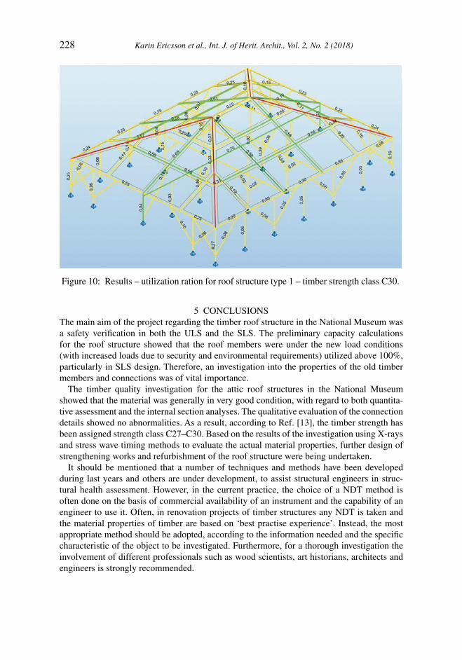
4.5 Structural analysis
For the structural assessment calculations, the geometrical survey data were used to prepare numerical 2D and 3D models. Figures 9 and 10 present the 3D numerical model of roof struc-ture type 1. The structural 3D modelling process did not focus on details (carpentry joints and connections) modelling. The structural analysis of roof types 1–3, with timber strength class assigned to C30, showed satisfactory results both in ULS and SLS designs. Only in roof type 1 four rafters and purlins were removed and exchanged with new glulam beams due to architectural design of new glass roof structure. Purlins in roof type 3 were also removed and exchanged with new glulam beams due to the same architectural design of glass roof structure. Roof structure type 2 was neither strengthened nor rebuilt from original design.
Figure 9: 3D numerical model
228 Karin Ericsson et al., Int. J. of Herit. Archit., Vol. 2, No. 2 (2018)
5 CONCLUSIONSThe main aim of the project regarding the timber roof structure in the National Museum was a safety verification in both the ULS and the SLS. The preliminary capacity calculations for the roof structure showed that the roof members were under the new load conditions (with increased loads due to security and environmental requirements) utilized above 100%, particularly in SLS design. Therefore, an investigation into the properties of the old timber members and connections was of vital importance.
The timber quality investigation for the attic roof structures in the National Museum showed that the material was generally in very good condition, with regard to both quantita-tive assessment and the internal section analyses. The qualitative evaluation of the connection details showed no abnormalities. As a result, according to Ref. [13], the timber strength has been assigned strength class C27–C30. Based on the results of the investigation using X-rays and stress wave timing methods to evaluate the actual material properties, further design of strengthening works and refurbishment of the roof structure were being undertaken.
It should be mentioned that a number of techniques and methods have been developed during last years and others are under development, to assist structural engineers in struc-tural health assessment. However, in the current practice, the choice of a NDT method is often done on the basis of commercial availability of an instrument and the capability of an engineer to use it. Often, in renovation projects of timber structures any NDT is taken and the material properties of timber are based on ‘best practise experience’. Instead, the most appropriate method should be adopted, according to the information needed and the specific characteristic of the object to be investigated. Furthermore, for a thorough investigation the involvement of different professionals such as wood scientists, art historians, architects and engineers is strongly recommended.
Figure 10: Results – utilization ration for roof structure type 1 – timber strength class C30.

Karin Ericsson et al., Int. J. of Herit. Archit., Vol. 2, No. 2 (2018) 229
REFERENCES [1] Riggio, M. & Tannert, T., Structural Assessment: diagnosis, before intervention! CD-
ROM Proceedings of the World Conference on Timber Engineering, 2016. [2] Nowak, T., Jasieńko, J. & Hamrol-Bielecka, K., In situ assessment of structural tim-
ber using the resistance drilling method – Evaluation of usefulness. Construction and Building Materials, 102, pp. 403–415, 2015. DOI: 10.1016/j.conbuildmat.2015.11.004.
[3] Feio, A.O., Machado, J.S. & Lourenço, P.B., Compressive behavior and NDT correla-tions for chestnut wood (Castanea sativa Mill.), Structural Analysis of Historical Con-structions, ed. C. Modena, P.B. Lourenço, P. Roca, Taylor & Francis Group: London, pp. 369–375, 2005.
[4] Kasal, B., Adams, A. & Drdacky, M., Application of digital radiography in evaluation of components of existing structures. RILEM Symposium on Site Assessment of Concrete, Masonry and Timber Structures – SACoMaTiS. Varenna – Lake Como, Italy, 2008.
[5] Lechner, T., Sandin, Y. & Kliger, R., Assessment of density in timber using X-ray equip-ment. International Journal of Architectural Heritage, 7(4), pp. 416–433, 2013. DOI: 10.1080/15583058.2011.642055.
[6] Dackermann, U., Crews, K., Kasal, B., Li, J., Riggio, M., Rinn F., et al. In-situ assess-ment of structural timber using stress-wave measurements. Materials and Structures, pp. 1–17, 2013. DOI: 10.1617/s11527-013-0095-4.
[7] Lechner, T., Nowak, T. & Kliger, R., In situ assessment of the timber floor structure of the Skansen Lejonet fortification, Sweden. Construction and Building Materials, 58, pp. 85–93, 2014. DOI: 10.1016/j.conbuildmat.2013.12.080.
[8] Tiago, I., Lechner. T. & Nowak, T., Assessment of timber floors by means of non-destructiv e testing methods. Construction and Building Materials, 101, pp. 1206–1214, 2015. DOI: 10.1016/j.conbuildmat.2015.05.133.
[9] Wang, X., Divos, F., Pilon, C., Brashaw, B.K., Ross, R.J. & Pellerin, R.F., Assessment of decay in standing timber using stress wave timing nondestructive evaluation tools. United States Department of Agriculture (USDA), General Technical Report FPL-GTR-147, pp. 1–12. 2004.
[10] Ross, R. J. & Pellerin, R. F., Nondestructive testing for assessing wood members in structures. United States Department of Agriculture (USDA), General Technical Report FPL-GTR-70, pp. 1–40, 1994.
[11] Dinwoodie, J., Timber: Its Nature and Behaviour, Taylor & Francis: London, 2000. [12] Glos P., Solid timber-strength classes. Timber Engineering STEP, Vol. 1, Centrum Hout
Almere: Netherlands, p. A7, 1995. [13] EN 338, Structural timber-strength classes. Comité Européen de Normalisation CEN,
2003. EN 338:2016. ICS: 79.040; 91.080.20; 92.300.20 [14] Jasieńko, J., Nowak, T. & Hamrol, K., Selected methods of diagnosis of historical timber
structures – principles and possibilities of assessment. Advanced Materials Research, 778, pp. 225–232, 2013. DOI: 10.4028/www.scientific.net/AMR.778.225.