non-destructive testing and analysis of a xix-century
TRANSCRIPT
NON-DESTRUCTIVE TESTING AND ANALYSIS OF
A XIX-CENTURY BRICK MASONRY BUILDING
A. HOŁA1, Ł. SADOWSKI2, J. SZYMANOWSKI3
The article presents the results of non-destructive testing and analyses carried out for a brick masonry building
from the 19th century, which has many irregularities that involve a lack of inspections and tests of its technical
condition for many years, as well as a failure to carry out necessary repairs. The conducted organoleptic tests
enabled the most significant building damage to be indicated, and its causes were determined on the basis of the
results of non-destructive tests and analyses. These causes include mainly wall cracks, ceiling deflections and
excessive dampness. It also contains the relationships, which were developed using non-destructive dielectric and
resistive methods when testing the moisture content of the brick walls. These results may be useful for other
researchers dealing with brick masonry buildings from a similar period of time. The authors' intention was to
present the existing poor technical condition of the brick masonry building and indicate its causes, as well as to
present that a lack of appropriate maintenance can lead to a situation in which the life or health of residents is
threatened.
Keywords: brick masonry building; wall cracks; ceiling deflections; excessive dampness; non-destructive testing
1 PhD., Eng., Wroclaw University of Science and Technology, Department of Building Engineering, Wybrzeże
Wyspiańskiego 27, 50-370 Wrocław, Poland, e-mail: [email protected] DSc., PhD., Eng., Wroclaw University of Science and Technology, Department of Building Engineering, Wybrzeże
Wyspiańskiego 27, 50-370 Wrocław, Poland, e-mail: [email protected] MSc.., PhD., Eng., Wroclaw University of Science and Technology, Department of Building Engineering, Wybrzeże
Wyspiańskiego 27, 50-370 Wrocław, Poland, e-mail: [email protected]
1. INTRODUCTION
Many countries in Europe are struggling with the problem of an unsatisfactory, or even poor, technical
condition of multi-family residential buildings that were built before World War II [1-3]. These brick
masonry buildings, in many cases, do not meet basic functional and utility requirements, regarding
e.g. mechanical resistance and stability, safety in case of fire, appropriate hygiene and health
conditions, environmental protection, safety in use, protection against noise and vibration, energy
economy and heat retention of partitions as well as sustainable use of natural resources [4-8].
Compliance with all the above-mentioned requirements is important, however, due to the health and
life of residents, it is particularly important to ensure the safety of the structure (it is not maintained
when the ultimate limit states of the basic structural elements are exceeded) and appropriate hygiene
and health conditions. In order to comply with the above-mentioned requirements, buildings should
be kept in an appropriate technical condition. Therefore, systematic periodic inspections and tests are
necessary, which allow interference in the tissue of an object to be significantly reduced [9-12]. Such
inspections therefore minimize the amount of local damage resulting from diagnostic tests [13].
Nowadays different non-destructive testing (NDT) methods are used in the assessment of different
types of masonry. For example ultrasonic testing has been successfully used to evaluate the
mechanical properties of clay masonry units [14] and weathered granites [15]. Also ground-
penetrating radar (GPR) has been applied to measure the moisture in full-scale stone and brick
masonry models after simulated flooding [16]. On the other side GPR, thermography and sonic tests
were applied successfully to evaluate the moisture distribution in the masonry after flooding and
during natural drying [17]. In [18] the infrared radiation has been used for thermal and mycological
active protection of baroque building.
Based on the results of the inspections and tests, it is possible to prepare a correct assessment of the
condition of the entire building and its individual elements, and thus conduct a proper renovation
policy [19-22]. However, it often happens that inspections and tests are not carried out regularly, and
in some cases, these omissions go back many years. It is also not uncommon that the recommended
repairs, based on the conducted inspections and tests, are not carried out.
This may result e.g. from an inefficient property management model, which especially applies to
buildings that have many co-owners, or even from a lack of funds that are needed to finance the
renovation [23-25]. The results of periodic inspections and tests should also be recorded in the
202 A. HO�A, �. SADOWSKI, J. SZYMANOWSKI
building's logbook, which is not always observed, and many buildings - especially those that are
centuries old or older - do not even have a building logbook.
Referring to the above statements, this article presents the case of a 120-year old brick masonry
building, which has irregularities within the basic functional and utility requirements indicated above.
This building, for many years, was not subjected to the necessary periodic inspections, tests and
renovations. The purpose of the paper is to present the existing poor technical condition of the brick
masonry building and to indicate its causes, as well as to highlight that a lack of proper maintenance
can lead to a situation in which the life or health of residents is endangered. The article contains the
results of tests and analyses, including non-destructive tests, on the basis of which the causes of
damage were determined.
2. GENERAL DESCRIPTION OF THE BRICK MASONRY BUILDING
The analysed building is located in the close vicinity of a street and was erected at the end of the 19th
century as a four-storey multi-family brick masonry building with a basement and an attic. It has no
foundation benches - it was founded on rocky ground. The basement walls had a thickness of about
550 mm were partly made of granite elements and partly of solid burnt clay brick. The view of
building location, facade with the main entrance to the building, facade from the yard and gable wall
of the building were presented in Fig. 1.
NON-DESTRUCTIVE TESTING AND ANALYSIS OF A XIX-CENTURY BRICK MASONRY... 203

Fig. 1. View of: a) building location, b) facade with the main entrance to the building, c) gable wall of the
building, d) facade from the yard
In turn, the walls of the over-ground storeys - internal with a thickness of 250 mm and 150 mm and
external with a thickness of 500 mm - were made of solid burnt clay brick and lime mortar. The
ceiling above the basement is segmental, built of brick with a thickness of 120 mm, expanded clay
with a thickness of 150 mm, 60 mm thick layer of concrete and 22 mm thick layer of boards on mud
(Fig. 2a). This ceiling is based on both the external walls and a steel 240 mm height IPN-beam running
through the central part of the basement. Above the other storeys there are wooden beam ceilings
with sound boarding (Fig. 2b). The load-bearing beam of this ceiling had dimensions of 140 x 18
mm. On this beam the wooden joist with a dimensions of 100 x 100 mm are placed.
204 A. HO�A, �. SADOWSKI, J. SZYMANOWSKI

(a)
(b)
Fig. 2. Cross-section of: a) the segmental ceiling above the basement, b) the wooden
ceiling above the first floor
The building is also covered with a roof queen post truss. The building has a staircase, the runs of
which are made of stone up to the first floor, while on the upper floors they are wooden. The building
has no damp insulation of its walls and basement floors, however, there is a perimeter drain that was
executed around it during its construction.
NON-DESTRUCTIVE TESTING AND ANALYSIS OF A XIX-CENTURY BRICK MASONRY... 205

3. RESULTS OF THE CONDUCTED TESTS AND ANALYSES
3.1. ORGANOLEPTIC TESTS
As a result of organoleptic tests (visual inspection), the condition of the brick masonry building was
assessed and the most significant damage was pointed out, namely:
- numerous vertical cracks and bulging towards the outside of one of the gable walls of the
brick masonry building. Deep cracks were also noticed in one longitudinal outer wall. There
was also local deformation and a deep crack along the entire height of the internal transverse
wall, as a result of which the brick lintel that is based on it is distorted above the entrance to
the basement, with the bricks being loose in the zone above the lintel. The locations of the
wall cracks are shown in Figure 1,
- strong corrosion of the I-section steel beam in the sectional ceiling in the basement. Rust
layers of 2 mm thick were easily detached from the bottom flange of this beam, and as a result
of which the cross-section of the beam was reduced by about 40%. In addition, a significant
deflection of the beam and its rotation in the plan were found. Therefore, it was recommended
to support it with a wooden support in order to prevent the ceiling above the basement from
collapsing,
- significant deflections of wooden ceilings over all the above-ground floors,
- a significant deviation regarding the level of the stone stairs that run from the ground floor to
the first floor, and which are based on the deformed and cracked transverse wall,
- strong dampness of the walls at the ground floor level, with salt efflorescence and mould fungi
on their surfaces.
The most important damage - cracked walls, significantly deflected ceilings, deformed stairs, and
also heavily damp ground floor walls covered with efflorescence of mould fungi that are harmful to
human health - clearly indicated the poor condition of the brick masonry building. Therefore, due to
the threat to the life or health of the residents, it was decided to move them out.
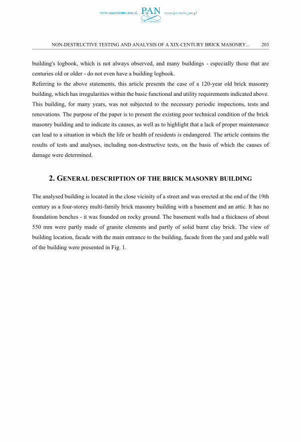
Figure 3 presents the wall cracks and deformed stone stairs, as well as a sketch of the second floor of
the brick masonry building, on which the direction of the support of the wooden ceilings is marked.
In the photo of the stairs, a dashed line shows a significant deviation of the stone treads from the
original level.
206 A. HO�A, �. SADOWSKI, J. SZYMANOWSKI
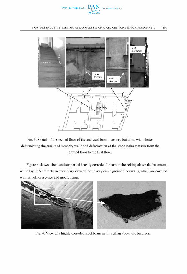
Fig. 3. Sketch of the second floor of the analysed brick masonry building, with photos
documenting the cracks of masonry walls and deformation of the stone stairs that run from the
ground floor to the first floor.
Figure 4 shows a bent and supported heavily corroded I-beam in the ceiling above the basement,
while Figure 5 presents an exemplary view of the heavily damp ground floor walls, which are covered
with salt efflorescence and mould fungi.
Fig. 4. View of a highly corroded steel beam in the ceiling above the basement.
NON-DESTRUCTIVE TESTING AND ANALYSIS OF A XIX-CENTURY BRICK MASONRY... 207
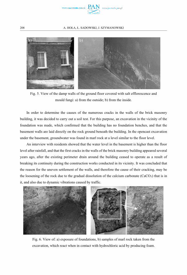
Fig. 5. View of the damp walls of the ground floor covered with salt efflorescence and
mould fungi: a) from the outside; b) from the inside.
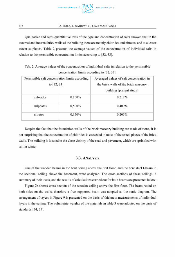
In order to determine the causes of the numerous cracks in the walls of the brick masonry
building, it was decided to carry out a soil test. For this purpose, an excavation in the vicinity of the
foundation was made, which confirmed that the building has no foundation benches, and that the
basement walls are laid directly on the rock ground beneath the building. In the opencast excavation
under the basement, groundwater was found in marl rock at a level similar to the floor level.
An interview with residents showed that the water level in the basement is higher than the floor
level after rainfall, and that the first cracks in the walls of the brick masonry building appeared several
years ago, after the existing perimeter drain around the building ceased to operate as a result of
breaking its continuity during the construction works conducted in its vicinity. It was concluded that
the reason for the uneven settlement of the walls, and therefore the cause of their cracking, may be
the loosening of the rock due to the gradual dissolution of the calcium carbonate (CaCO3) that is in
it, and also due to dynamic vibrations caused by traffic.
Fig. 6. View of: a) exposure of foundations, b) samples of marl rock taken from the
excavation, which react when in contact with hydrochloric acid by producing foam.
208 A. HO�A, �. SADOWSKI, J. SZYMANOWSKI

Laboratory tests showed that the ground under the brick masonry building is mudstone with a
high marl content. This was also confirmed by tests with the use of hydrochloric acid. Figure 6 shows
the foundations that were uncovered in the basement in the corner of the outer walls, a view of the
rock sample taken for laboratory testing, and the reaction of the mudstone to contact with
hydrochloric acid (foam).
3.2. MOISTURE CONTENT AND SALINITY TESTS ON BRICK WALLS
Tests were carried out in order to determine the degree and causes of the strong dampness and
salinity of the building's walls. Due to the poor technical condition of the walls and the lack of
conservation restrictions, it was possible to carry out moisture tests using the destructive gravimetric
method. However, it was decided to also use two non-destructive methods in the research, dielectric
(Gann Hydromette Uni 2 meter) and resistance (Gann Hydromette RTU 600 meter) [26-28] in order
to determine for each of them the exact correlative dependencies between the unitless X indications
of the meters and the mass moisture content Umof the wall, as described in [28]. These dependencies,
which are shown in Figure 7, can be used by other researchers who deal with brick masonry buildings
from a similar period, especially historic ones, in which the interference in the historical tissue is very
limited due to restoration restrictions.
a) b)
Fig. 7. Correlational relationship between the indications X of the meter and the mass
moisture content Um of the masonry wall: a) for the dielectric meter; b) for the resistance
meter.
The brick external and internal walls of the ground floor were subjected to the tests.
Measurements were taken in eight measuring places, in each place at four heights above floor/ground
level, as shown at Figure 8. In total, for each of methods 32 measurements were obtained.
NON-DESTRUCTIVE TESTING AND ANALYSIS OF A XIX-CENTURY BRICK MASONRY... 209

Fig. 8. The location of measuring places of the mass moisture content Um of the masonry walls
The average values of the moisture content in the subsurface zone, determined at heights of 20
cm, 50 cm, 100 cm and 150 cm above the floor level, were equal to 6.40% (SD = 3,50), 4.70% (SD
= 2,38), 3.50% (SD = 0,55) and 2.60% (SD = 1,11) respectively for the internal walls, and for the
external walls they were equal to 10.20% (SD = 3,37), 6.80% (SD = 1,33), 3.80% (SD = 0,64) and
2.35% (SD = 0,59), respectively. This state is illustrated in Figure 9. Table 1 presents the classification
of the moisture content adopted from literature [29-31], and the determined degree of dampness of
particular batches of the tested walls. The measurement results clearly show that the building's walls
are excessively damp up to a height of about 130 cm above floor level.
210 A. HO�A, �. SADOWSKI, J. SZYMANOWSKI

Fig. 9. Averaged mass moisture content distributions Ūm in the masonry walls of the
ground floor: a) at the height of the internal walls, obtained using the dielectric method; b)
at the height of the outer walls, obtained using the resistance method.
Tab. 1. The degree of dampness of particular batches of the tested walls in relation to the
classification of the moisture content in brick walls adopted in literature [29-31].
Classification of the moisture content in brick walls according to [26-28]
Moisture content in the tested brick walls [present study]
Mass moisture content Um [%]
The degree of dampness Internal walls External walls
<3.0 wall with permissible moisture content
more than ~130 cm above the floor level
more than ~130 cm above the floor level
3.0–5.0 wall with increased moisture content
up to ~130 cm above the floor level
up to ~130 cm above the floor level
5.0–8.0 moderately damp wall up to ~45 cm above the floor level
up to ~75 cm above the floor level
8.0–12.0 very damp wall - up to ~40 cm above the floor level
>12.0 wet wall - -
NON-DESTRUCTIVE TESTING AND ANALYSIS OF A XIX-CENTURY BRICK MASONRY... 211
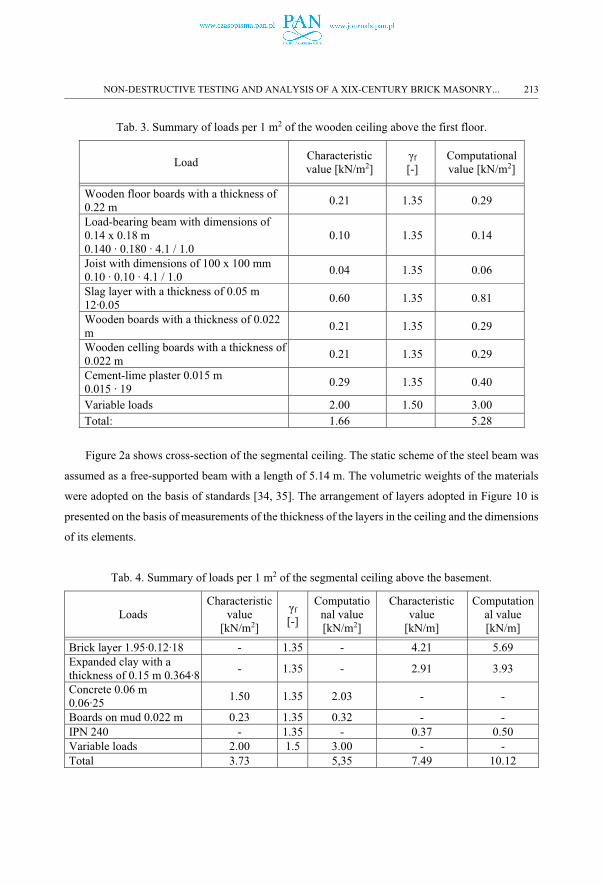
Qualitative and semi-quantitative tests of the type and concentration of salts showed that in the
external and internal brick walls of the building there are mainly chlorides and nitrates, and to a lesser
extent sulphates. Table 2 presents the average values of the concentration of individual salts in
relation to the permissible concentration limits according to [32, 33].
Tab. 2. Average values of the concentration of individual salts in relation to the permissible
concentration limits according to [32, 33].
Permissible salt concentration limits according
to [32, 33]
Averaged values of salt concentration in
the brick walls of the brick masonry
building [present study]
chlorides 0.150% 0.211%
sulphates 0,500% 0,409%
nitrates 0,150% 0,205%
Despite the fact that the foundation walls of the brick masonry building are made of stone, it is
not surprising that the concentration of chlorides is exceeded in most of the tested places of the brick
walls. The building is located in the close vicinity of the road and pavement, which are sprinkled with
salt in winter.
3.3. ANALYSIS
One of the wooden beams in the bent ceiling above the first floor, and the bent steel I-beam in
the sectional ceiling above the basement, were analysed. The cross-sections of these ceilings, a
summary of their loads, and the results of calculations carried out for both beams are presented below.
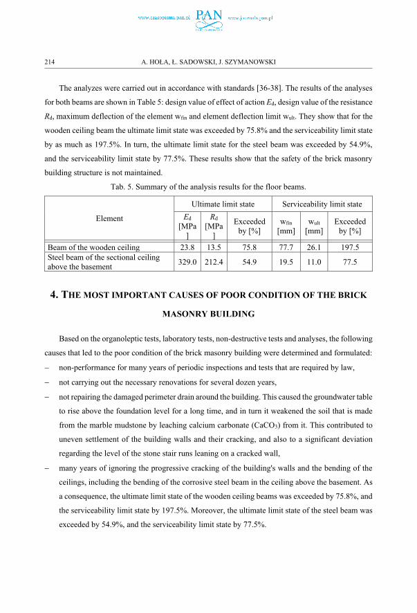
Figure 2b shows cross-section of the wooden ceiling above the first floor. The beam rested on
both sides on the walls, therefore a free-supported beam was adopted as the static diagram. The
arrangement of layers in Figure 9 is presented on the basis of thickness measurements of individual
layers in the ceiling. The volumetric weights of the materials in table 3 were adopted on the basis of
standards [34, 35].
212 A. HO�A, �. SADOWSKI, J. SZYMANOWSKI
Tab. 3. Summary of loads per 1 m2 of the wooden ceiling above the first floor.
LoadCharacteristic value [kN/m2]
γf
[-]Computational value [kN/m2]
Wooden floor boards with a thickness of 0.22 m
0.21 1.35 0.29
Load-bearing beam with dimensions of 0.14 x 0.18 m 0.140 ∙ 0.180 ∙ 4.1 / 1.0
0.10 1.35 0.14
Joist with dimensions of 100 x 100 mm 0.10 ∙ 0.10 ∙ 4.1 / 1.0
0.04 1.35 0.06
Slag layer with a thickness of 0.05 m12∙0.05
0.60 1.35 0.81
Wooden boards with a thickness of 0.022 m
0.21 1.35 0.29
Wooden celling boards with a thickness of 0.022 m
0.21 1.35 0.29
Cement-lime plaster 0.015 m0.015 ∙ 19
0.29 1.35 0.40
Variable loads 2.00 1.50 3.00Total: 1.66 5.28
Figure 2a shows cross-section of the segmental ceiling. The static scheme of the steel beam was
assumed as a free-supported beam with a length of 5.14 m. The volumetric weights of the materials
were adopted on the basis of standards [34, 35]. The arrangement of layers adopted in Figure 10 is
presented on the basis of measurements of the thickness of the layers in the ceiling and the dimensions
of its elements.
Tab. 4. Summary of loads per 1 m2 of the segmental ceiling above the basement.
LoadsCharacteristic
value [kN/m2]
γf
[-]
Computational value [kN/m2]
Characteristic value
[kN/m]
Computational value [kN/m]
Brick layer 1.95∙0.12∙18 - 1.35 - 4.21 5.69Expanded clay with a thickness of 0.15 m 0.364∙8
- 1.35 - 2.91 3.93
Concrete 0.06 m 0.06∙25
1.50 1.35 2.03 - -
Boards on mud 0.022 m 0.23 1.35 0.32 - -IPN 240 - 1.35 - 0.37 0.50Variable loads 2.00 1.5 3.00 - -Total 3.73 5,35 7.49 10.12
NON-DESTRUCTIVE TESTING AND ANALYSIS OF A XIX-CENTURY BRICK MASONRY... 213
The analyzes were carried out in accordance with standards [36-38]. The results of the analyses
for both beams are shown in Table 5: design value of effect of action Ed, design value of the resistance
Rd, maximum deflection of the element wfin and element deflection limit wult. They show that for the
wooden ceiling beam the ultimate limit state was exceeded by 75.8% and the serviceability limit state
by as much as 197.5%. In turn, the ultimate limit state for the steel beam was exceeded by 54.9%,
and the serviceability limit state by 77.5%. These results show that the safety of the brick masonry
building structure is not maintained.
Tab. 5. Summary of the analysis results for the floor beams.
Element
Ultimate limit state Serviceability limit state
Ed
[MPa]
Rd
[MPa]
Exceeded by [%]
wfin
[mm]wult
[mm]Exceeded
by [%]
Beam of the wooden ceiling 23.8 13.5 75.8 77.7 26.1 197.5Steel beam of the sectional ceiling above the basement
329.0 212.4 54.9 19.5 11.0 77.5
4. THE MOST IMPORTANT CAUSES OF POOR CONDITION OF THE BRICK
MASONRY BUILDING
Based on the organoleptic tests, laboratory tests, non-destructive tests and analyses, the following
causes that led to the poor condition of the brick masonry building were determined and formulated:
� non-performance for many years of periodic inspections and tests that are required by law,
� not carrying out the necessary renovations for several dozen years,
� not repairing the damaged perimeter drain around the building. This caused the groundwater table
to rise above the foundation level for a long time, and in turn it weakened the soil that is made
from the marble mudstone by leaching calcium carbonate (CaCO3) from it. This contributed to
uneven settlement of the building walls and their cracking, and also to a significant deviation
regarding the level of the stone stair runs leaning on a cracked wall,
� many years of ignoring the progressive cracking of the building's walls and the bending of the
ceilings, including the bending of the corrosive steel beam in the ceiling above the basement. As
a consequence, the ultimate limit state of the wooden ceiling beams was exceeded by 75.8%, and
the serviceability limit state by 197.5%. Moreover, the ultimate limit state of the steel beam was
exceeded by 54.9%, and the serviceability limit state by 77.5%.
214 A. HO�A, �. SADOWSKI, J. SZYMANOWSKI
5. GENERAL RECOMMENDATIONS TO BRING THE BUILDING INTO
TECHNICAL CONDITION GUARANTEEING SAFE USE
In order to bring the building into technical condition guaranteeing safe use, it is necessary to
undergo general renovation. The scope of renovation should include:
- replacement of all ceilings with new, massive ones. The ceiling on steel beams with reinforced
concrete slab and expanded clay block is recommended in this case. Steel beams at the support points
must be absolutely anchored to the walls and with each other and, moreover, connected with
perpendicular stiffening steel ribs, so that the creation of rigid horizontal discs by individual floors.
The gable walls should be anchored with such ceilings,
- lamping the steel structure of a bulging gable wall with perpendicular external and internal walls, at
the level of the ceiling above the first and second floor,
- re-walling the entire internal wall with a chimney shaft and filling in the basement walls of mortar
losses between stone elements using lime mortar similar to these used originally together with the
replacement of rotten mortar to the depth that will be possible,
- analyse the structural behaviour of masonry walls with the special focus on the presence of in-plane
damage (e. g. cross fracture as discussed in [39-41]), out-of-plane damage (e. g. wall deflection as
discussed in [42-44]) and combined in-plane and out-of-plane damage of walls (for guidance’s see
for example here [45-47]),
- repair (stitching with steel rods placed in the wall joints) cracks occurring in external and internal
walls,
- replacement of internal stairs with new reinforced concrete
- vertical insulation of foundation walls, unblocking the band drainage system that had functioned in
the past, and the horizontal floor in the basement and on the ground floor in the basement,
- insulation of the external partitions in order to improve the thermal insulation of the building. It
should be considered in the context of the requirements in the European standard [48],
- replacement of windows and doors with new wooden ones, windows should be equipped with air
inlets ensuring air supply to the interior of the building
- recreation of all building finishes with the use of materials intended for use in historic buildings,
characterized by, among others, low diffusion resistance.
These works should be preceded by making an inventory of the building for design purposes, and
then by carrying out an appropriate construction design. At the design stage, the heating problem
should be solved.
NON-DESTRUCTIVE TESTING AND ANALYSIS OF A XIX-CENTURY BRICK MASONRY... 215
6. SUMMARY
The article presents the results of non-destructive tests and analyses for a brick masonry building
from the 19th century, which has many irregularities that involve a lack of inspections and tests of its
technical condition for many years, as well as a failure to carry out necessary repairs. This situation
led to the building being in such a bad condition that it was necessary to move out its residents due
to a threat to their life or health. The basic requirements for ensuring the safety of the structure and
appropriate hygiene and health conditions were not met. The conducted organoleptic tests enabled
the most significant building damage to be indicated, and its causes were determined on the basis of
the results of non-destructive tests and analyses. The purpose of the article is to present the existing
poor technical condition of the brick masonry building and to indicate its causes, as well as to
highlight that a lack of appropriate maintenance can lead to a situation where the life or health of
residents is endangered
REFERENCES
1. Klõšeiko, Paul, Agasild, T.; and Kalamees, T. Deterioration of building envelope of wooden apartment buildings built before 1940 based on external survey. Proceedings of 9th Nordic Symposium on Building Physics–NSB 2011. Vol. 2, 917-924.
2. Nowogońska, B. (2019). Diagnoses in the Aging Process of Residential Buildings Constructed Using Traditional Technology. Buildings, 9(5), 126.
3. Balaras, C.A.; Droutsa, K.; Dascalaki, E.; Kontoyiannidis, S. Deterioration of European apartment buildings. Energy and Buildings, 2005, 37, 515-527.
4. Rozporządzenie Ministra Spraw Wewnętrznych i Administracji z dnia 16 sierpnia 1999 r. w sprawie warunków technicznych użytkowania budynków mieszkalnych (Dz. U. z 1999 r. Nr 74 poz. 836).
5. Regulation (EU) No 305/2011 of the European Parliament and of the Council of 9 March 2011 laying down harmonised conditions for the marketing of construction products and repealing Council Directive 89/106/EEC Text with EEA relevance
6. Gorzelańczyk, T., & Hoła, J. (2015). Stress failure of cement concretes under compression–synthesis of knowledge, conclusions. Journal of Civil Engineering and Management, 21(1), 1-10.
7. Glavaš, H., Hadzima-Nyarko, M., Buljan, I. H., & Barić, T. (2019). Locating Hidden Elements in Walls of Cultural Heritage Buildings by Using Infrared Thermography. Buildings, 9(2), 32.
8. Syczewski, M. Eksploatacyjne problemy techniczne w starych budynkach wielorodzinnych po modernizacji dachów. Budownictwo i Inżynieria Środowiska, 2011, 2(4), 677-680.
9. Hoła, J., & Runkiewicz, L. (2018). Methods and diagnostic techniques used to analyse the technical state of reinforced concrete structures. Structure and Environment, 2018, 10 (4), 309-337.
10. Knyziak, P. (2016). The quality and reliability in the structural design, production, execution and maintenanceof the precast residential buildings in Poland in the past and now. In Key Engineering Materials (Vol. 691, pp. 420-431). Trans Tech Publications.
11. Jaskowska-Lemańska, J., Wałach, D., & Sagan, J. (2016). Technical condition assessment of historical buildings-flowchart development. Infrastruktura i Ekologia Terenów Wiejskich, 2016, 4 (4), 1755-1769.
12. Knyziak, P., Krentowski, J. R., & Bieranowski, P. (2017). Risks of the Durability of Large-Panel Buildings Elevations in Reference to the Conclusions from Technical Conditions Audits. In MATEC Web of Conferences (Vol. 117, p. 00080). EDP Sciences.
13. Concu, G., Trulli, N. & Valdés, M. (2018). Knowledge Acquisition of Existing Buildings by Means of Diagnostic Surveying. Case Studies. International Journal of Structural Glass and Advanced Materials Research, 2(1), 22-29
216 A. HO�A, �. SADOWSKI, J. SZYMANOWSKI
14. Noor-E-Khuda, Sarkar; & Albermani, Faris. (2019) Mechanical properties of clay masonry units: destructive and ultrasonic testing. Construction and Building Materials, 219, 111-120.
15. Noor-E-Khuda, Sarkar; Albermani, Faris; & Veidt, Martin. (2017) Flexural strength of weathered granites: influence of freeze and thaw cycles, Construction and Building Materials, 156, 891-901
16. Cardani, G., Cantini, L., Munda, S., Zanzi, L., & Binda, L. (2013). Non invasive measurements of moisture in full-scale stone and brick masonry models after simulated flooding: effectiveness of GPR. In Nondestructive Testing of Materials and Structures (pp. 1143-1149). Springer, Dordrecht
17. Binda, L., Cardani, G., & Zanzi, L. (2010). Nondestructive testing evaluation of drying process in flooded full-scale masonry walls. Journal of Performance of Constructed Facilities, 24(5), 473-483
18. Robert Wójcik & Piotr Kosiński (2019) Thermal and mycological nondestructive active protection of baroque buildings, Science and Technology for the Built Environment, 25:9, 1244-1252, DOI: 10.1080/23744731.2019.1629240.
19. Nowogońska, B. Diagnoza w procesie starzenia budynków mieszkalnych wykonanych w technologii tradycyjnej. Warszawa: Komitet Inżynierii Lądowej i Wodnej PAN, 2017
20. Rodrigues, F., Matos, R., Di Prizio, M., & Costa, A. (2018). Conservation level of residential buildings: Methodology evolution. Construction and Building Materials, 172, 781-786.
21. Sobotka, A., & Radziejowska, A. (2019). Risk analysis in the realization of buildings in revitalized areas. Archives of Civil Engineering, 65(3).
22. Nowogońska, B. (2016). Proposal for determing the scale of renovation needs of residential buildings. Civil andEnvironmental Engineering Reports, 22(3), 137-144.
23. Domański, T., & Matysek, P. (2018). The reliability of masonry structures–evaluation methods for historical buildings. Czasopismo Techniczne, 2018(Volume 9), 91108.
24. Lujanen, M. Legal challenges in ensuring regular maintenance and repairs of owner-occupied apartment blocks. International Journal of Law in the Built Environment, 2010, 2(2), 178-197.
25. Ustawa z dnia 7 lipca 1994 r. Prawo budowlane (tekst jednolity z 2006 r. Dz. U. Nr 156 poz. 1118 z późn. zm.).26. Hoła, A. Measuring of the moisture content in brick walls of historical buildings the overview of methods, 3rd
International Conference on Innovative Materials, Structures and Technologies (IMST 2017) [Dokument elektroniczny]: 27-29 September 2017, Riga, Latvia. [Bristol]: IOP Publishing
27. Goetzke-Pala, A.; Hoła, J. Influence of burnt clay brick salinity on moisture content evaluated by non-destructive electric methods. Archives of Civil and Mechanical Engineering, 2016, 6(1), 101-111.
28. Hoła, J. Degradacja budynków zabytkowych wskutek nadmiernego zawilgocenia – wybrane problemy. Budownictwo i Architektura, 2018, 17(1), 133-148.
29. Adamowski, J.; Hoła, J.; Matkowski, Z. Probleme und Lösungen beim Feuchtigkeitsschutz des Mauerwerks von Baudenkmälern am Beispiel zweier grosser Barockbauten in Wrocław, Bautechnik, 2005, 82(7), 426–433.
30. Rokiel M. Hydroizolacje w budownictwie. Wybrane zagadnienia w praktyce, wyd. II rozszerzone; Dom Wydawniczy MEDIUM, Warszawa, 2009.
31. CSN P 73 0610. Waterproofing of buildings – The rehabilitation of damp masonry and additional protection of buildings against ground moisture and against atmospheric water – The basic provision (2000).
32. WTA 2-6-99-D. Erganzungen zum WTA-Merkblatt 2-2-91-D. Sanierputzsysteme (1991).33. Hoła J.; Matkowski Z. Ocena skuteczności przeciwwilgociowych izolacji wtórnych na przykładzie trzech
zabytkowych obiektów we Wrocławiu. In Trwałość i skuteczność napraw obiektów budowlanych, red. Kamiński M. i in.; Dolnośląskie Wydawnictwo Edukacyjne, Wrocław, 2007, s. 129-138
34. EN 1991-1-1: 2004 – Actions on structures35. PN-82 B-02001 – Permanent loads (in polish)36. EN 1990: Basis of structural design37. EN 1995-1-1: Design of timber structures38. EN 1993-1-1: Design of steel structures39. Vasconcelos, G., & Lourenço, P. B. (2009). In-plane experimental behavior of stone masonry walls under cyclic
loading. Journal of structural engineering, 135(10), 1269-1277. 40. Lourenço, P. B., Oliveira, D. V., Roca, P., & Orduña, A. (2005). Dry joint stone masonry walls subjected to in-
plane combined loading. Journal of Structural Engineering, 131(11), 1665-1673. 41. Dhanasekar, M., Thamboo, J. A., & Nazir, S. (2017). On the in-plane shear response of the high bond strength
concrete masonry walls. Materials and Structures, 50(5), 21442. Noor-E-Khuda, Sarkar; Dhanasekar, Manicka; & Thambiratnam, David P. (2016) Out-of-plane deformation and
failure of masonry walls with various forms of reinforcement. Composite Structures, 140, pp. 262 – 277. 43. Noor-E-Khuda, S., & Dhanasekar, M. (2020). On the out-of-plane flexural design of reinforced masonry walls.
Journal of Building Engineering, 27, 100945. 44. Noor-E-Khuda, S., Dhanasekar, M., & Thambiratnam, D. P. (2016). An explicit finite element modelling method
for masonry walls under out-of-plane loading. Engineering Structures, 113, 103-120
NON-DESTRUCTIVE TESTING AND ANALYSIS OF A XIX-CENTURY BRICK MASONRY... 217
45. Noor-E-Khuda, Sarkar; & Dhanasekar, Manicka. (2018) Three sides supported unreinforced masonry walls under multidirectional loading. Construction and Building Materials, 188, 1207-1220.
46. Najafgholipour, M. A., Maheri, M. R., & Lourenço, P. B. (2013). Capacity interaction in brick masonry under simultaneous in-plane and out-of-plane loads. Construction and building materials, 38, 619-626.
47. Noor-E-Khuda, S., & Dhanasekar, M. (2017). Masonry walls under combined in-plane and out-of-plane loadings. Journal of Structural Engineering, 144(2), 04017186
48. EN 16883 Conservation of cultural heritage - Guidelines for improving the energy performance of historic buildings.
LIST OF FIGURES AND TABLES:
Fig. 1. View of: a) building location, b) facade with the main entrance to the building, c) gable wall of the building, d) facade from the yard
Rys. 1. Widok: a) lokalizacji budynku, b) fasady z głównym wejściem do budynku, c) ściany szczytowej budynku, d) fasady od strony dziedzińca
Fig. 2. Cross-section of: a) the segmental ceiling above the basement, b) the wooden ceiling above the first floor
Rys. 2. Przekrój: a) stropu odcinkowego nad piwnicą, b) stropu drewnianego nad pierwszym piętrem
Fig. 3. Sketch of the second floor of the analysed brick masonry building, with photos documenting the cracks of masonry walls and deformation of the stone stairs that run from the ground floor to the first floor.
Rys. 3. Szkic drugiego piętra analizowanego budynku z cegły murowanej, ze zdjęciami dokumentującymipęknięcia ścian muru i deformację kamiennych schodów biegnących od parteru do pierwszego piętra.
Fig. 4. View of a highly corroded steel beam in the ceiling above the basement.
Rys. 4. Widok mocno skorodowanej stalowej belki w stropie nad piwnicą.
Fig. 5. View of the damp walls of the ground floor covered with salt efflorescence and mould fungi: a) from the outside; b) from the inside.
Rys. 5. Widok wilgotnych ścian parteru pokrytych wykwitami solnymi i grzybami pleśniowymi: a) z zewnątrz; b) od wewnątrz.
Fig. 6. View of: a) exposure of foundations, b) samples of marl rock taken from the excavation, which react when in contact with hydrochloric acid by producing foam.
Rys. 6. Widok: a) ekspozycji fundamentów, b) próbek skały margla pobranej z wyrobiska, które reagują w kontakcie z kwasem chlorowodorowym wytwarzając pianę.
Fig. 7. Correlational relationship between the indications X of the meter and the mass moisture content Um of the masonry wall: a) for the dielectric meter; b) for the resistance meter.
Rys. 7. Zależność korelacyjna między wskazaniami X miernika a masową wilgotnością Um ściany muru: a) dla miernika dielektrycznego; b) dla miernika rezystancji.
Fig. 8. The location of measuring places of the mass moisture content Um of the masonry walls
218 A. HO�A, �. SADOWSKI, J. SZYMANOWSKI

Rys. 8. Lokalizacja miejsc pomiaru masy wilgotności wilgoci Um ścian murowanych
Fig. 9. Averaged mass moisture content distributions Um in the masonry walls of the ground floor: a) at the height of the internal walls, obtained using the dielectric method; b) at the height of the outer walls, obtained using the resistance method.
Ryc. 9. Uśrednione rozkłady zawartości wilgotności Um w ścianach murowanych parteru: a) na wysokości ścian wewnętrznych, uzyskane metodą dielektryczną; b) na wysokości ścian zewnętrznych, uzyskane metodą oporności.
Tab. 1. The degree of dampness of particular batches of the tested walls in relation to the classification of the moisture content in brick walls adopted in literature [27-29].
Tab. 1. Stopień zawilgocenia poszczególnych partii badanych ścian w stosunku do przyjętej w literaturze klasyfikacji wilgotności w murach ceglanych [27–29].
Tab. 2. Average values of the concentration of individual salts in relation to the permissible concentration limits according to [30, 31].
Tab. 2. Średnie wartości stężenia poszczególnych soli w stosunku do dopuszczalnych granic stężenia zgodnie z [30, 31].
Tab. 3. Summary of loads per 1 m2 of the wooden ceiling above the first floor.
Tab. 3. Podsumowanie obciążeń na 1 m2 stropu drewnianego nad pierwszym piętrem.
Tab. 4. Summary of loads per 1 m2 of the segmental ceiling above the basement.
Tab. 4. Podsumowanie obciążeń na 1 m2 stropu odcinkowego nad piwnicą.
Tab. 5. Summary of the analysis results for the floor beams.
Tab. 5. Podsumowanie wyników analizy dla belek stropowych.
Received: 01.03.2020, Revised: 15.09.2020
NON-DESTRUCTIVE TESTING AND ANALYSIS OF A XIX-CENTURY BRICK MASONRY... 219