nominal charge us$ 20 emf report edition 1 values for rf radiation from 30 khz to 300 ghz and also...
TRANSCRIPT

EMF REPORTEd
ition 1
Nomina
l cha
rge U
S$ 20
IMPRINT
Authors :
Hans-Joachim Förster, EMF Section Leader,Wandel & Goltermann GmbH & Co.D-72800 Eningen, GermanyFax: +49-7121-86-1480
Professors Y. Grigoriev, O. Grigoriev, A. MerkulovCentre of Electromagnetic SafetyMoscow, Zhivopisnaya st. 46Russia, 123 182Fax: +7-095-190-3590
Ing. HTL Matthias SchwendimannEMF problems, electrotechnical experiments and measurements,Construction Dept., Swiss Federal Railways SSBMittelstr. 43, CH-3030 Bern, SwitzerlandFax: +41-51-220-3922
Dr.-Ing. Klaus SchüringOtto Junker GmbHD-52074 Aachen, GermanyFax: +49-241-76 917
Prof. Dr. med. Wolfgang MangoldD-72800 Eningen, Germany
Hans-Peter SteimelPrecision Engineers and Electrotechnical Trade AcsociationGustav-Heinemann-Ufer 130D-50968 Köln, GermanyFax: +49-221-3778-723
Dave Brian, Manager Antenna Systems Group, NTLWinchester, Hants SO21 2QA, United KingdomFax: +44-1962-822-569
James B. Hatfield, P.E.Hatfield & DawsonConsulting Electrical Engineers4226 Sixth Ave. N.W.Seattle, Washington 98107, USAFax: +1-206-789-9834
Doc. Dr. Dina SimunicUniversity of ZagrebFaculty of Electrical Engineering and ComputingDept. of Radiocommunications and MicrowavesUnska 3, HR-10000 Zagreb, CroatiaFax: +385-1-6129-606
Angelika JetterFreelance JournalistReutlingen, GermanyFax: +49-7121-260197
Concept and Layout :Werbeagentur WaiblingerReutlingen
Production :Bernd Schepper
Photographs :Weber & Gnamm StudiosNTL (p. 19) Das Fotoarchiv (p. 18)AUVA (p. 14)Wandel & Goltermann archives
Repro : Gänßlen GmbH, Grafisches SystemhausBaindt-Schachen
Printers :Oertel + Spörer GmbH+Co.,ReutlingenPrinted on chlorine-free bleached paper
Published by :Wandel & GoltermannElektronische Meßtechnik GmbHSafety Test SolutionsMühleweg 5D-72800 Eningen u.A., Germanyemail: [email protected]://www.wg.com
Order no :E 10/12.97/WG1/210/5
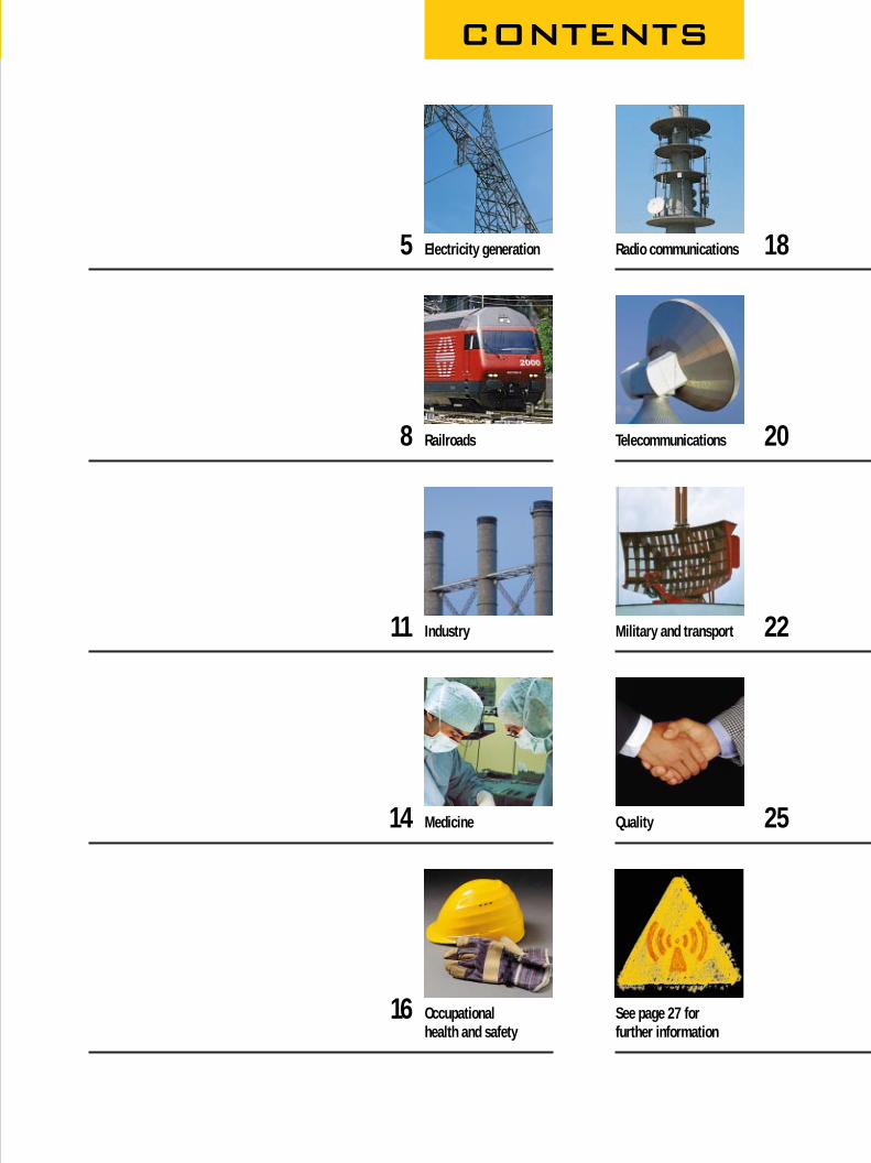
5 Electricity generation Radio communications 18
8 Railroads Telecommunications 20
11 Industry Military and transport 22
14 Medicine Quality 25
16 Occupational See page 27 forhealth and safety further information
CONTENTS
FOREWORD FOREWORD FOREWORD
4
Growing environmental awareness
and repeated reports on the potential
negative effects of electromagnetic
fields, commonly known as electro-
smog, on the human organism are
increasingly giving rise to public
debate on this subject.
GUIDELINES
Even though scientific proof of the
harmfulness or indeed harmlessness
of electrosmog has yet to be estab-
lished, the desire for precautionary
measures means that the call for
political and legal regulations has
continued unabated. The determina-
tion of exposure limits was set in
motion at the beginning of the 90’s:
The IRPA (International Radiation Pro-
tection Association) has issued new
guidelines, Germany has promulgated
a law on exposure levels for the
general public, Switzerland has an-
nounced a regulation governing field
concentrations in the workplace,
Australia is working on a new standard
and revised limit values, and in the
USA this year, the new FCC Standard
for the telecommunications branch
was brought into force.
MEASURING TECHNOLOGY
Such guidelines bring about the need
to monitor workplaces or areas of
exposure accessible to the public for
compliance with the applicable stan-
dards; members of the public who
spend time in these areas must be
protected and warned if necessary.
The challenge facing the measuring
technology required for this task is,
above all, to provide users with
simple, reliable and practical systems.
After all, people’s safety – and therefore
your safety – is at stake.
INNOVATIONS
Wandel & Goltermann are facing this
challenge and designing user-friendly
“technology for the protection of
health”. Here, as always, you can
count on decisively innovative steps :
Radiation meters with 60 dB dynamic
range, personal monitors capable
of simultaneously measuring electric
and magnetic fields, analyzers with
selective frequency display, long cali-
bration intervals of at least two years,
and three-dimensional measurement
of low-frequency electric fields.
IN PRACTICE
This report is a response to the
frequent questions asked by our
customers regarding the use of these
instruments in practice and inter-
national experience. The background
is world-wide endeavour in standard-
izing regulations on limit values and
harmonizing measurement procedures.
REPORTS
In the extracts of reports that follow,
users of Wandel & Goltermann systems
speak out on the basis of their
personal specialist knowledge, organ-
izational background and national
environment.
CURIOUS?
You may rightly be eager to find out
what is in the following reports of
people’s experiences. It only remains
for me to thank all those involved.
I am convinced that we are thereby
contributing to the recognition of
“electrosmog” as a valid object of
scientific study. The first step is the
reproducible measurement of fields.
A possible second step would be your
own personal experiences – surely a
valuable contribution to this inter-
national exchange of information. The
editors would therefore be glad to
hear from you by post, fax or email.
Dear Reader,

ELECTRICITY GENERATION·E
5
T he experts at the Centre for Electro-
magnetic Safety periodically conduct
measurements of the strength of power
supply frequency (50 Hz) electric and magnetic
fields in living quarters located in the immediate
proximity of power distribution system units,
such as transformer substa-
tions, switchboards, etc. We
successfully use the EFA-3
electromagnetic field analyzer
with precision H-field sensor
(A = 100 cm2).
Unfortunately, in Russia there
are currently no national stan-
dards regulating limit values
for electromagnetic radiation
levels in a given situation.
Therefore, we are usually
guided by the limit values
which are specified in the
Swedish MPR-II standard, and
by the recommendations of
the Swedish Radiation Pro-
tection Institute and National
Board of Occupational Safety
and Health. We accept an
electric field strength limit
value of 25 V/m and a
magnetic flux density limit
value of 200 µT.
The measurement method we use is quite simple
and, in our view, effective. The surface of the
room to be measured is divided into square
elemental cells so that a grid pattern is formed,
and measurements are taken at the nodes. As
the electromagnetic field structure is inhomo-
geneous, the measurements at each point are
made at heights of 0.5, 1.0 and 1.7 m above floor
level. The highest of the three values is con-
sidered as the defining value.
Results stored in the internal memory of the EFA-3
are transmitted to a PC using the Transfer Set via
a optical interface. Here, data recording and
consequent processing are carried out with the
help of programs such as Microsoft® Excel™.
Investigation of Electro-magnetic Exposure in Living QuartersLocated close to power distribution system objects, using the EFA-3 field analyzer system
Prof. Yuri Grigoriev,radiobiologist, scientificcoordinator of theRussian researchprogram investigatingthe biological effects ofnon-ionizing radiationand General Director of the Centre forElectromagnetic Safety(photo) ;Oleg Grigoriev,physicist, Director of the Centre forElectromagneticSafety ;Dr. Anton Merkulov,Specialist forelectromagnetic safety ;Moscow, Russia
When measuring electric field strength, as here in a 50 Hztransformer substation, a tripod should be used as the human body affects the field
P

ELECTRICITY GENERATION · ELECTRIC
6
The results of the processed data are
represented in Figures 1 and 2. Safe
areas, where electromagnetic field
levels do not exceed the limit values,
are marked in white.
Analysis of the results obtained shows
that in approximately 90 % of the
cases investigated, power distribution
system objects are sources of signifi-
cant levels of power supply frequency
electromagnetic radiation (its mag-
netic component, in particular).
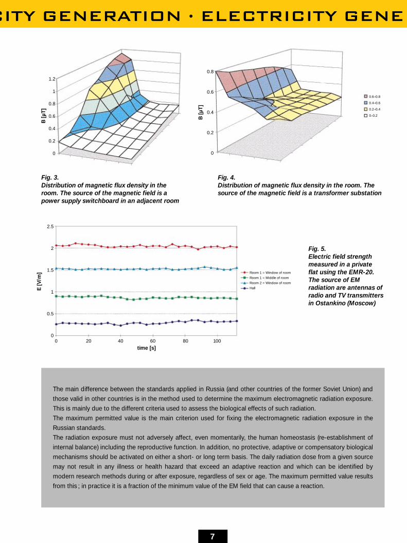
Tests with the EMR-20 in the vicinity
of radio and TV transmitters
We measured the electromagnetic
radiation in the vicinity of the Moscow
TV and FM broadcasting centre in
Ostankino. Using a spectrum analyzer,
we determined that the major RF
sources were in the VHF range (30 to
300 MHz). We therefore performed the
measurements using the EMR-20 with
a calibration factor k = 1, because only
a low radiation level was expected
(below 10 V/m).
The standard we used for this high-
frequency range is “The sanitary
regulations and norms for protection
of the population of Moscow City from
electromagnetic fields generated by
transmitting radio engineering objects”
(1996). This official document defines
limit values for RF radiation from
30 kHz to 300 GHz and also specifies
a measurement method. It provides for
the following frequency ranges: 0.03
to 3 MHz, 3 to 30 MHz, 30 to 300 MHz
and 0.3 to 300 GHz. The limit values
are shown in the table.
The limit value for the case named
above (VHF range) is 2 V/m, this was
slightly exceeded at some places
within the dwelling that we investi-
gated. O
Limit values for frequency ranges
0.03 to 3 MHz 3 to 30 MHz 30 to 300 MHz 0.3 to 300 GHz
V/m V/m V/m µW/cm2
1. Urban 15.0 10.0 3.0 3.0area
2. Work- 15.0 10.0 3.0 3.0place
3. Public 10.0 7.0 2.0 2.0areas
Fig. 1. Electric field strength distribution in a roomsituated close to a transformer substation
Fig. 2. Distribution of magnetic flux density ina room situated close to a transformersubstation
E [V
/m]
B [µ
T]
150
125
100
75
50
25
0
1
0.8
0.6
0.4
0.2
0
CITY GENERATION · ELECTRICITY GENE
7
The main difference between the standards applied in Russia (and other countries of the former Soviet Union) and
those valid in other countries is in the method used to determine the maximum electromagnetic radiation exposure.
This is mainly due to the different criteria used to assess the biological effects of such radiation.
The maximum permitted value is the main criterion used for fixing the electromagnetic radiation exposure in the
Russian standards.
The radiation exposure must not adversely affect, even momentarily, the human homeostasis (re-establishment of
internal balance) including the reproductive function. In addition, no protective, adaptive or compensatory biological
mechanisms should be activated on either a short- or long term basis. The daily radiation dose from a given source
may not result in any illness or health hazard that exceed an adaptive reaction and which can be identified by
modern research methods during or after exposure, regardless of sex or age. The maximum permitted value results
from this ; in practice it is a fraction of the minimum value of the EM field that can cause a reaction.
Fig. 3. Distribution of magnetic flux density in theroom. The source of the magnetic field is apower supply switchboard in an adjacent room
Fig. 4. Distribution of magnetic flux density in the room. Thesource of the magnetic field is a transformer substation
Fig. 5. Electric field strengthmeasured in a private flat using the EMR-20. The source of EM radiation are antennas ofradio and TV transmittersin Ostankino (Moscow)
B [µ
T]
B [µ
T]
E [V
/m] Room 1 = Window of room
Room 1 = Middle of room
Room 2 = Window of room
Hall
0.6–0.8
0.4–0.6
0.2–0.4
0–0.2
time [s]
1.2
1
0.8
0.6
0.4
0.2
0
0.8
0.6
0.4
0.2
0
2.5
2
1.5
1
0.5
00 20 40 60 80 100

RAILROADS RAILROADS RAILR
8
H-field Measurementsin the IC-2000H-field influences in double-decker coaches and in the track area
Increasingly in modern trains, more and more
appliances are being installed to bring about
greater performance and comfort. The grow-
ing need for such devices compels designers to
locate strong magnetic field sources, such
as transformers, interphase transformers and
high-voltage power cables in areas which are
susceptible to interference. Sensitive areas are
electronic cubicles in the trains or safety devices
along the track. Another peculiarity typical of
railways is the single-phase power supply system
(outgoing and return conductors situated far
apart from one another) which allows the
generation of uncompensated fields. The
passenger coaches of modern passenger trains,
likewise, are increasingly exposed to strong
magnetic fields. These require particular atten-
tion, as the conditions for people with pace-
makers, at the least, must be complied with.
Measurements in the passenger compartment
The measurements were intended to provide in-
formation about potential magnetic field sources,
the characteristic of the magnetic field over time
and the intensity of the exposure. As extremely
influential magnetic field sources, the bus bar of
the train in the floor of the lower deck (electric
power supply for the entire train) and the contact
line were in the foreground. The requirements for
the measuring instruments were as follows:
• Automatic measurement with accurate
recording of measured values
• Evaluation of field axes and frequencies
• Frequency sampling rate at least every 5
seconds, in certain cases up to 3 values per sec.
• Transferability of measured data to PC in
common data formats; simultaneous evaluation
of the results from several instruments must be
possible with the PC.
Ing. HTL MatthiasSchwendimann,responsible formatters relating toEMC and EDPmeasuring technologywithin the groupElectrotechnical Testsand Measurements of the ConstructionManagement of theSwiss Railways, Bern, Switzerland.

OADS RAILROADS RAILROADS RAILR
9
The above conditions led us to
use three EM field analyzers type
EFA-3 and EFA-2 from Wandel &
Goltermann.
The evaluations of the measurements
produced the following results:
Value while setting up the train: 22 µT
Value during operation: 9 µT. In the top
deck, the influence of the contact line
is dominant, in the lower deck the in-
fluence of the train bus bar.
Precautionary value: 100 µT (values
are far below this).
As expected, the magnetic field char-
acteristic was discontinuous. The
graph shows a typical characteristic of
the magnetic field with the associated
current values.
Measurements taken around the track
were intended to provide information
concerning the strength of the mag-
netic field generated by the train bus
bar. Conditions in the area of the rails
are extremely complex. The fields of
the rails carrying reverse current
overlap the fields of passing trains.
For measuring the electrical inter-
Positioning the instruments in the coach
Location of the Field source Targetmeasuring instrument
Lower deck, centre of Influence of Field exposure incoach with “reference train bus bar the seating area instrument” and (mathematical)
estimation ofexposure in thearea of the track
Top deck, coach centre Influence of Field exposure in of instrument positions train bus bar and the seating area
contact line
Section through the double-decker
coach and position ofmeasuring instruments
Evaluation of measurement results stored in the EFA-3 by PC shortly aftermeasurement
Test point 2Various locations
Test point 1,fixed unit
BUS
Magnetic field measurementsIC-2000Journey 14.5. 45346, BUS ON/OFF testsTest instrument location : Coach centre, 0.5 m from floor,Location : 1st A coach, 1st coach after locomotive
Lower deck seat 36
Upper deck seat 111
I_bus
I_primary
TP_rails
Adjacent frame
Indu
ctio
n B
[µT]
I[A
]
25
20
15
10
5
0
800
700
600
500
400
300
200
100
0
09:0
3
09:0
5
09:0
7
09:0
9
09:1
1
09:1
2
09:1
4
09:1
6
09:1
8
09:2
0
09:2
1
09:2
3
Test probe : Wandel & Goltermann EFA-2 / C-0054 Pass through rail-side measuring pointP

RAILROADS RAILROADS RAILROADS
10
ference of apparatus, the sum total
field is the decisive factor. For a
precise assessment, the signals have
to be recorded in a transparent
manner and evaluated with the aid of
plotters or oscilloscopes.
A parallel measurement using the EM
analyzers of Wandel & Goltermann
with an external probe in the area of
the rails raised the following ques-
tions:
Is remote control via PC worthwhile
for hard use in the field?
The evaluation produced the following
results:
Up to train speeds of 40 km/h, a
simple rail current including H-field
train profile can be measured using
one instrument.
At higher speeds, the instrument at
least permits conclusions to be drawn
(with exact recording of measure-
ments) with regard to rail currents. O
Attachment of the magnetic fieldprobe inside the tracks
Non-contact measurement of rail currents
Magnetic field measurementsIC-2000Test 46362, rapid braking with magnetic rail brakesMeasurement at rail base
Indu
ctio
n B
[µT]
140
120
100
80
60
40
20
0
15:2
8:52
15:2
8:57
15:2
9:02
15:2
9:07
15:2
9:12
15:2
9:17
15:2
9:22
15:2
9:27
15:2
9:32
15:2
9:37
15:2
9:42
15:2
9:48
15:2
9:53
15:2
9:58
15:3
0:03
15:3
0:08
15:3
0:13
Test probe : Wandel & Goltermann EFA-3 / D-0024 Time interval (3 seconds)
First axle
Can the rail currents be measured
simply using the WG probe, without
contact and with no need for compli-
cated apparatus?
Can this simple measuring system be
used to produce standard H-field
characteristics for the rolling stock?
Is a sampling rate of 3 measured
values per second sufficient?
*
* Locomotive

INDUSTRY INDUSTRY INDUS
11
In the Work Environ-ment of modernInduction FurnacesMeasurements of electromagnetic fields in industrial plants
Dr. Ing. Klaus SchüringOtto Junker GmbH,Germany
T he potential harmful effects of electro-
magnetic fields on the human organism
are now subject to regulations and
standards which define the requirements for
personal health and safety at home and at work.
Whereas numerous limit values have been deter-
mined for the actual fields, applicable definitions
for measuring procedures and radiation exposure
are still lacking, particularly where occupational
safety is concerned. This report puts forward
proposals for ways to approach this problem. It
provides examples of measurements of flux
density in alternating magnetic fields, which were
conducted in the work environment of industrial
induction furnaces. The results of the measure-
ments are confirmed by calculations which also
help to illustrate the typical magnetic fields of
these induction furnaces. The influence of
specific furnace designs on the stray magnetic
field is demonstrated by means of two furnaces
of almost identical size. Finally, there follows a
description of the measuring systems employed :
a simple 100 cm2 standard coil connected to an
RMS voltmeter for anisotropic measurements,
and a digital field analyzer with an isotropic 3D
probe.
The stray magnetic fields outside these induction
furnaces are extremely inhomogeneous, but are
generally sinusoidal on a single-frequency, in line
with the induction currents. Their values
decrease considerably the greater the distance
from the source.
Measurements of the magnetic field
on the platform of a medium-sized induction
furnace MFTGe 3t / 1.6 MW / 250 Hz
Field experts of the Institute for Electrical
Machines at the Technical University of Aachen
[2] have conducted a systematic study of the
magnetic field on the platform of a medium-sized
induction furnace type MFTGe 3t / 1.6 MW /
250 Hz (Figure 1). The measurements were
carried out at three different heights: at 0.9 m,
1.25 m and 1.55 m above the reference points
marked on the platform of the furnace (Figure 1).
The values determined at a height of 0.9 m are
represented as iso-induction curves. Their course
is not coaxial to the coil due to the influence on
the platform of metallic objects in the proximity of
the furnace and due to the strong currents
feeding the coil (Figure 1). The values M
measured at 0.9 m between reference points A
and A´ in Figure 1 were entered in a graph with
values which were calculated with the aid of 2D
and 3D simulation (Figure 2). The 3D calculations
clearly match the test results, whereas the 2D
calculations produce somewhat higher values.
The graph also shows that induction diminishes
with the distance from the coil. It must be noted
at this point that only the values in the accessible
area are relevant for measuring the possible
radiation exposure of personnel, and that this
zone commences at point A. In order to clarify
the relationship to existing or proposed limit
values, the following limit-value curves for the
operating frequency of 250 Hz were incorporated
in the graph: Blim = 320 µT according to Standard
ENV 50166 and EU Proposal [3]P
INDUSTRY INDUSTRY INDUSTRY INDU
12
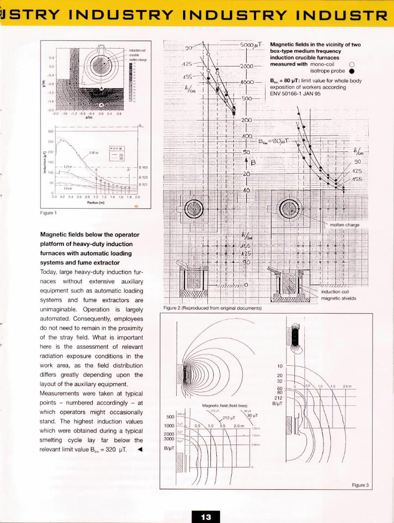
BAL1 = 40 µT (action level 1)
BAL2 = 80 µT (action level 2)
BAL3 = 128 µT (action level 3)
The induction values in the work area
lie far below Blim, sufficiently below
action levels 2 and 3 and, at a dis-
tance from the furnace cover of 0.5 m
or more, even below action level 1.
Magnetic fields from two
box-shaped furnaces of similar
size but different design
Measurements carried out on two
box-shaped 1000 Hz furnaces of al-
most identical size (1.0 t and 1.2 t
loading capacity) for aluminium bronze
revealed the enormous influence of
design features on the shape and size
of the stray field (see Figure 2). Both
furnaces project beyond the operator
platform by approx. 50% of the size of
an operator. The stray magnetic field
in the operating area of furnace A),
with a nominal capacity of 450 kW
and without a magnetic screen,
reaches values of between 300 µT and
3300 µT, which considerably exceed
the relevant limit value Blim = 80 µT to
ENV 50166, not to mention BAL3 = 32 µT,
action level 3 of the EU Proposal [1].
On the other hand, the corresponding
values for furnace B), with a nominal
capacity of 500 kW, lie far below these
limit values at 10 µT and 63 µT.
The measurements were conducted
using two different measuring sys-
tems, for which 100 cm2 coils were
employed in each case :
One of the systems used of an an-
isotropic measuring probe, a simple
100 cm2 flat coil connected to an RMS
voltmeter. This permitted the measure-
ment of a single axis. The probe had
to be rotated until the position where
the maximum reading was obtained
was found. At a frequency of 50 Hz,
1 VRMS on the voltmeter corresponds to
an average field density of 1 mT in the
coil. At other frequencies, the value
obtained must be multiplied by the
factor 50/f/Hz.
The other system used an isotropic
probe with an analyzer [2] featuring a
digital readout and storage capa-
bilities for the date, time, frequency
and all three measured values. The
savings in time and improved reliability
justify the expense of the system after
just a few test series. However, the
operating range of the EFA-2 system
from Wandel & Goltermann was insuf-
ficient with regard to the field values
in the furnace without a magnetic
screen, which exceeded the relevant
limit values. Fortunately, the simple
anisotropic system was available to
complete the measurement. The
results portrayed in Figure 2 confirm
the extent to which the results from
the two measurement systems
matched up.
The measured conditions are repre-
sented by the calculated magnetic
fields (field curves) and the ISO-induc-
tion curves (see Figure 2) in a convinc-
ing manner. It is evident that the lack
of magnetic screens gives rise to a
much larger stray field than is the case
with a screened furnace.
Bibliographical referencesExtract from the discourse “Electromagnetic fields in the working area of modern induction crucible furnaces” held at the “Electromagnetic Processing of Materials” CFE International Conference, Paris, May 26–29, 1997[1] Berufsgenossenschaft der Feinmechanik und Elektrotechnik, “Regeln für Sicherheit und Gesundheitsschutz an Arbeitsplätzen mit Exposition durch elektrische, magnetische oder elektromagnetische Felder”
(“Rules for safety and health protection at working posts exposed to electric, magnetic and electromagnetic fields” (Edition 10/95 Gustav-Heinemann-Ufer 130 – 50968 Cologne, Germany).[2] T.BAUER, S.DAPPEN, G.HENNEBERGER und R. JORDAN (Institut für Elektrische Maschinen RWTH Aachen). “Reduction of Electromagnetic Field Emission of Inductive Devices” 3rd International Workshop on Electric
and Magnetic Fields - from Numerical Models to Industrial Applications, Liège, 6th to 9th May 1996.
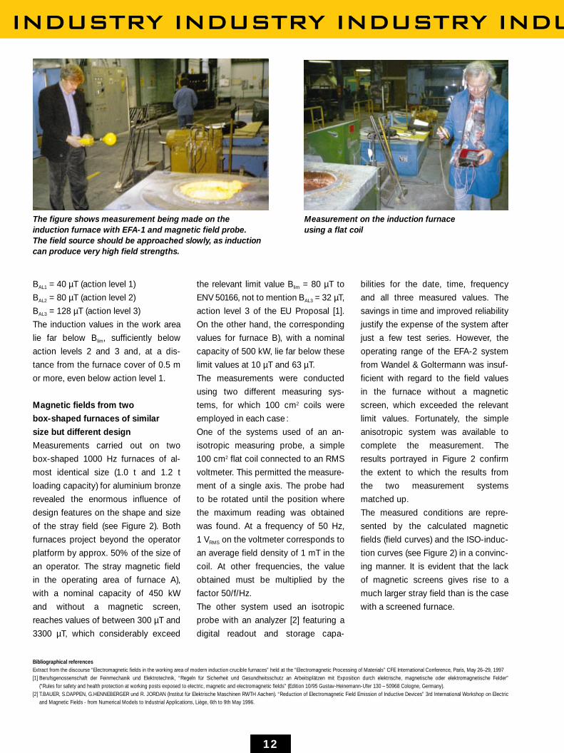
The figure shows measurement being made on the induction furnace with EFA-1 and magnetic field probe. The field source should be approached slowly, as inductioncan produce very high field strengths.
Measurement on the induction furnace using a flat coil
MEDICINE MEDICINE MEDICIN
14
Prof. Dr. med. Wolfgang MangoldGeneral Practitioner,Head for many years of the Faculty ofGeneral Medicine at the University of Tübingen ; Eningen u.A.,Germany
Electrosmog inHospitals and DoctorsSurgeries ?Potential sources of danger are often unknown
E quipment in hospitals and surgeries is
intended for the benefit of people’s
health. However, one often overlooks
the fact that the electrosmog generated by some
appliances represents an unnecessary health
hazard for their operators.
Effects on health
Patients and health service personnel are thus
exposed to considerable magnetic fields, in NMR
tomography, for example. These direct-current
magnetic fields, which are a feature of the tech-
nology in use, may lead to feelings of ill health
once they reach a certain strength. The influence
of strong magnetic fields upon human ECG
curves is also medically proven. The extensive
consequences of these non-thermal effects are
being discussed in medical scientific circles.
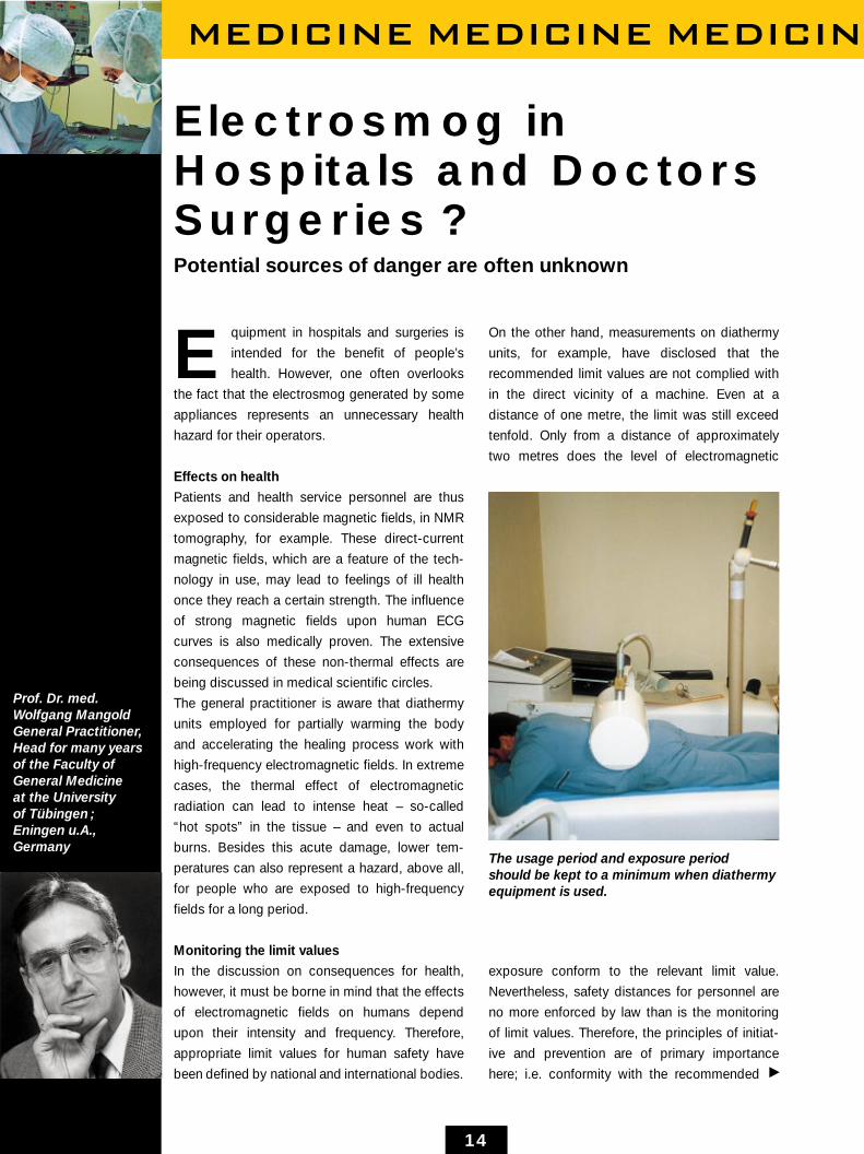
The general practitioner is aware that diathermy
units employed for partially warming the body
and accelerating the healing process work with
high-frequency electromagnetic fields. In extreme
cases, the thermal effect of electromagnetic
radiation can lead to intense heat – so-called
“hot spots” in the tissue – and even to actual
burns. Besides this acute damage, lower tem-
peratures can also represent a hazard, above all,
for people who are exposed to high-frequency
fields for a long period.
Monitoring the limit values
In the discussion on consequences for health,
however, it must be borne in mind that the effects
of electromagnetic fields on humans depend
upon their intensity and frequency. Therefore,
appropriate limit values for human safety have
been defined by national and international bodies.
On the other hand, measurements on diathermy
units, for example, have disclosed that the
recommended limit values are not complied with
in the direct vicinity of a machine. Even at a
distance of one metre, the limit was still exceed
tenfold. Only from a distance of approximately
two metres does the level of electromagnetic
exposure conform to the relevant limit value.
Nevertheless, safety distances for personnel are
no more enforced by law than is the monitoring
of limit values. Therefore, the principles of initiat-
ive and prevention are of primary importance
here; i.e. conformity with the recommended
The usage period and exposure period should be kept to a minimum when diathermyequipment is used.
P
E MEDICINE MEDICINE MEDICINE MED
15
limit values should be monitored even
without legal obligation to do so.
Wherever possible, sources of hazard-
ous electromagnetic fields should be
avoided or minimised. This also
applies in particular to hospitals and
doctors surgeries, which occupy a
special position in the alternating field
between sickness and health.
Interference to sensitive equipment
In addition to the direct risk to health
posed by electromagnetic fields,
people are also exposed to an indirect
risk: Equipment such as an ECG or an
electronically controlled drip may
malfunction as a result of electro-
magnetic fields, thereby giving rise to
situations which may at times be
lifethreatening. Furthermore, patients
with pacemakers, for example, are
also endangered by electromagnetic
radiation which, in the worst case,
may cause these devices to fail.
The ban on mobile phones in hospitals
clearly demonstrates how sensitive
this area is. The electromagnetic
waves emitted whilst telephoning can
impair sensitive equipment in the
hospital as well as the pacemaker of
a patient. However, if one compares
the mobile phone, which functions at
2 watts, with diathermy units, which
have an output of 500 watts, it
becomes clear which sources of
danger are being completely ignored.
Since magnetic fields penetrate
virtually all materials, even reinforced
concrete walls and ceilings, the
selection of the best location for an
NMR tomograph, or a hyperthermy or
diathermy unit, is a matter of con-
siderable importance. The machines
should be erected in a place where
there are no patients in direct proxim-
ity, including in neighbouring rooms or
on adjacent floors. Only in this way
can electromagnetic exposure of the
body be kept to a minimum. Moreover,
when selecting locations for such
equipment, care must be taken to
ensure that no sensitive devices are
nearby. In this case, too, measuring
instruments should be used to
examine how high electromagnetic
exposure levels are and how this
could give rise to interference.
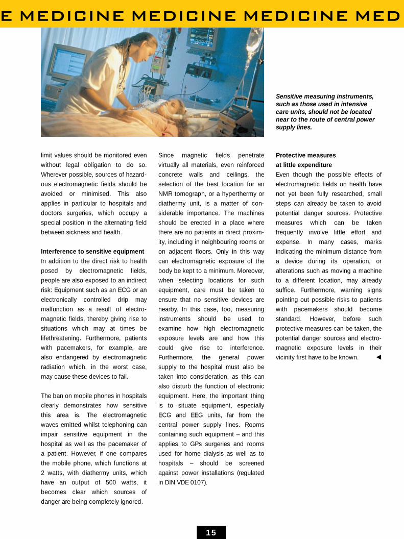
Furthermore, the general power
supply to the hospital must also be
taken into consideration, as this can
also disturb the function of electronic
equipment. Here, the important thing
is to situate equipment, especially
ECG and EEG units, far from the
central power supply lines. Rooms
containing such equipment – and this
applies to GPs surgeries and rooms
used for home dialysis as well as to
hospitals – should be screened
against power installations (regulated
in DIN VDE 0107).
Protective measures
at little expenditure
Even though the possible effects of
electromagnetic fields on health have
not yet been fully researched, small
steps can already be taken to avoid
potential danger sources. Protective
measures which can be taken
frequently involve little effort and
expense. In many cases, marks
indicating the minimum distance from
a device during its operation, or
alterations such as moving a machine
to a different location, may already
suffice. Furthermore, warning signs
pointing out possible risks to patients
with pacemakers should become
standard. However, before such
protective measures can be taken, the
potential danger sources and electro-
magnetic exposure levels in their
vicinity first have to be known. O
Sensitive measuring instruments,such as those used in intensivecare units, should not be locatednear to the route of central powersupply lines.

OCCUPATIONAL HEALTH AND S
16
Safety at WorkThe EMF measuring service of the employers’ liability insurance association for precision mechanics and electrical engineering
Hans-Peter Steimel,Employers’ liabilityinsurance associationfor precisionmechanics andelectrical engineering,Cologne, Germany
“Cologne. Recently, in addition to the already
established measuring services for deter-
mining noise conditions and exposure to
pollution at the workplace, the employers’
liability insurance association began providing
a further highly topical and urgently needed
measuring service: the determination of
exposure to electric, magnetic and electro-
magnetic fields.”
T his, or something similar, was what
appeared in the newspapers over the
last few months. But what is actually
behind this new measuring service?
Its objective, above all, is to offer a qualified
measuring service in the area of field measure-
ments to those insured by the employers’ liability
insurance association for precision mechanics
and electrical engineering, as well as to those
insured by other such associations and those
with personal accident insurance. This new
service is also available to all interested parties,
however.
The need for such a measuring service has
evolved due to the fact that the generation, trans-
mission, distribution and consumption of
electrical energy and its use in the transmission
of signals in telecommunications is closely
associated with electric, magnetic and electro-
magnetic fields. The resulting exposure, par-
ticularly at the affected workplaces, must be
considered as an environmental factor in the
issue of occupational safety.
Areas of application which give rise to fields
are present in industry in the most varied
situations. For example, static fields occur during
electrolysis and in electroplating. Medicine makes
use of high static fields in magnetic resonance
(MR) tomography and spectroscopy.
The low-frequency range from 1 Hz to 30 kHz
is the range used by broad sections of industry,
e.g. metallurgy, induction heating, welding or
even demagnetisation. Of course, all electrical
energy supply and distribution (50 Hz) also lies in
this frequency range, as does the supply and
distribution of power for railways (162/3 Hz).
However, the high-frequency range – above
30 kHz – is also often employed in industry.
Whereas inductive processes tend to use the
low-frequency range, capacitive applications
such as wood drying and veneer processing or
the welding of plastics also generate high
frequencies.
One extensively used process is induction
hardening, with both low and high-frequency
fields. Lastly, a further industrial application is the
microwave (2.45 GHz), which is used for drying
and curing in the manufacture of rubber.
This brief list of applications demonstrates how
widespread the use of fields is in our working
environment. All the more reason why we should
ensure safety at workplaces with exposure to
electric, magnetic or electromagnetic fields.
In the interests of occupational health and
safety, the committee of experts for electrical
engineering determined rules for workplaces as
early as 1982, and these are set out in the
electrical engineering rules of Standard DIN VDE
0848, which apply to Germany. In 1995, these
were revised and brought into force as the “Rules
for the protection of health and safety at work-
places with exposure to electric, magnetic or
electromagnetic fields (MBL 16)”.
In addition to limit values, these rules also
contain instructions on measurement and the

SAFETY · OCCUPATIONAL HEALTH AND
17
assessment of measured values. An
accident prevention regulation dealing
with fields is currently in preparation.
This confirms the need, both of
employees with accident insurance
and employers, for the creation of a
legal basis for occupational safety.
The “EMF measuring service”
sees its primary task as
• The measurement of workplace-
related field strengths
• The assessment of measured
values in accordance with
currently applicable standards
• Advising businesses.
A large variety of modern measuring
instruments is available for measuring
the very wide band of frequencies
from 0 Hz to 40 GHz. One of these
instruments, which covers the
frequency band from 5 Hz to 30 kHz,
is the field analyzer system EFA-3
from Wandel & Goltermann. This very
robustly designed measuring system
features excellent characteristics for
measuring exposure at the workplace.
During our search for a suitable
measuring system, the following
properties formed the most important
criterion for our decision:
• The precision of isotropic
measuring probes for magnetic
and electric fields
• The compact design – vital with
regard to transport and ease of
carrying
• User-definable filter
• Simple operation
• and the possibility of storing
technical data so that it can
subsequently be used on a PC.
The filters, in particular, which are set
for certain frequencies but can be
freely defined by the user, enable
the correct assessment of fields in
industrial applications. A few weeks
ago, for example, measurements were
carried out to determine exposure at
different points in the vicinity of an
extremely powerful converter plant
(nominal output 100 MW, frequency
162/3 Hz / 50 Hz). This measurement
showed that not only did the
fundamental frequencies 162/3 Hz and
50 Hz contribute considerably to
exposure levels, but also the harmonic
waves at 331/3 and 100 Hz. Thus, near
the transformers a magnetic flux
density of 3.3 mT was measured at a
frequency of 331/3 Hz. The permitted
value in exposure zone 1, at 2.04 mT,
is greatly exceeded. This area there-
fore suffers from increased exposure,
and as such, the permitted value of
3.82 mT must be applied and the time
spent in this area restricted to two
hours a day.
If we had only measured the funda-
mental frequencies in this case, we
would have come to fully the wrong
conclusion, since these exposure
levels were by far within the permitted
range and even clearly below the
lower values of exposure zone 2. With
field measuring instruments which
only measure the broadband, do not
indicate the dominant frequency and
are unable to filter different fre-
quencies individually, correct assess-
ment would not have been possible. In
contrast, however, the EFA-3 field
analyzer from Wandel & Goltermann
proved to be a well-equipped, user-
friendly and reliable instrument for
field measurements. O
Mangnetic field measurementof an EDM machine
Permitted values of magnetic flux density in exposure ranges 1 and 2
Stimuli Heating
Peak limit value
VDE exposure range 1
VDE exposure range 2
VDE K1h VDE E1VDE K2h VDE E2
10’ 10’ 10’ 10’ 10’ 10’ 10’ 10’
<10’ 10’ 10’ 10’ 10’
•• [Hz]
10’
[V/m]
10’
10’
10’
10’
10’

RADIO COMMUNICATIONS · RA
18
NTL, Winchester, Great BritainDave Brian, Manager Antenna Systems Group
Safety inTransmitting Stations Training and check measurements as the first step
O ne of NTL’s roles in the UK is
the responsibilty for operating the
independent UHF TV broadcast
transmitter network for Channels 3, 4 & 5, plus
most of the independent broadcast radio
systems, both MF and VHF. Our many hilltop
sites also carry other systems (NTL & non-NTL)
on their masts and towers, covering the whole
range of powers and frequencies.
As a result of the RF
concentration on our sites,
we have had to develop
methods of ensuring staff
safety, particularly for climb-
ing staff. This includes our
customers and suppliers
staff who need access to
our structures, as well as
our own engineers, techni-
cians and riggers.
Good working practice,
staff training & awareness,
and careful control
procedures are the primary
means for ensuring this
safety. However RF
instrumentation is also an
important element. Over
the past two years we have
introduced the widespread
use of personal RF
monitors to support our
methods.
We realised that they are not a “magic” solution
and should only be used with care by trained
staff. We normally work in the “near field”
RF environment and unless staff have at
least a basic understanding of the physics of
RF and the meters, then the benefit of using
them can, in our view, be lost. We have therefore
developed an internal training scheme for all our
climbers.
As a back up to the
personal monitors we
have recently equipped
several teams with EMR
meters from Wandel &
Goltermann. These pre-
cision RF meters are
intended for use by fully
trained engineers to survey
areas where experience or
personal monitors indicate
a potential safety problem.
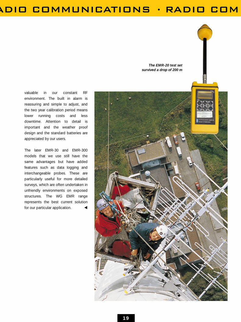
We managed to carry out
an “unplanned test” of
an early EMR-20 by
accidentally dropping it
from about 200 m from our
Black Hill mast in Scotland.
The strong design ensured
that only a minor repair
was needed ! The
instruments are compact,
easy to use and robust.
The auto zero is especially
It is important for maintenance personnelworking on RF antennas to carry awarning and measuring device with largefrequency and dynamic ranges
ADIO COMMUNICATIONS · RADIO COM
19
valuable in our constant RF
environment. The built in alarm is
reassuring and simple to adjust, and
the two year calibration period means
lower running costs and less
downtime. Attention to detail is
important and the weather proof
design and the standard batteries are
appreciated by our users.
The later EMR-30 and EMR-300
models that we use still have the
same advantages but have added
features such as data logging and
interchangeable probes. These are
particularly useful for more detailed
surveys, which are often undertaken in
unfriendly environments on exposed
structures. The WG EMR range
represents the best current solution
for our particular application. O
The EMR-20 test setsurvived a drop of 200 m
TELECOMMUNICATIONS TELEC
20
The Facts must be knownInterview on real EMF dangers and limit values
James B. Hatfield,Partner of Hatfield &Dawson ConsultingEngineers, Inc. ; Seattle, U.S.A.
James B. Hatfield, P.E. is a partner in the firm of
Hatfield & Dawson Consulting Engineers Inc.
which is established worldwide in the design,
analysis, adjustment and measurement of MW,
VHF, UHF and microwave antenna systems. They
have been involved in projects in Poland, Armenia,
United Kingdom, Taiwan, etc. Determining
compliance with federal and local RF safety
guidelines are a major activity of Hatfield and
Dawson. J. Hatfield has written several papers
and articles on the subject and delivered a
series of papers at meetings of the NAB, IEEE
Broadcast Technology Symposia, American
Society of Civil Engineers and at Wireless
Buildout Conferences, etc. A description of RF
compliance issues from a consulting engineers
perspective follows.
Why is EMF so important for you?
There is a perception of hazard on the part
of some members of the general public from
exposure to RF fields from antennas that have
brought to their attention at locations of high
visibility. We have been called upon by federal
and local governmental agencies and private
companies to provide expert testimony at various
land use hearings and other public forums. There
is a general misunderstanding of the
science behind RF safety standard setting on the
part of the public that can only be addressed by
education of those concerned. I am a member of
IEEE SCC28 and its five subcommittees and, as
such, am actively engaged in the standard
setting process. We provide consultation to
public agencies and private companies to help
them grapple with the issues of compliance with
new ANSI, FCC and local EMF regulations.
Can it be said that there are certain critical
situations in which possible danger exists?
RF safety standards are set between 10 and 50
times lower than demonstrable biological effects.
The issues of standards compliance and danger
are separate and distinct. The greatest hazard
that we normally deal with is that of RF shock
and burns from induced RF energy from MW
antennas in large cranes. Actual hazards may
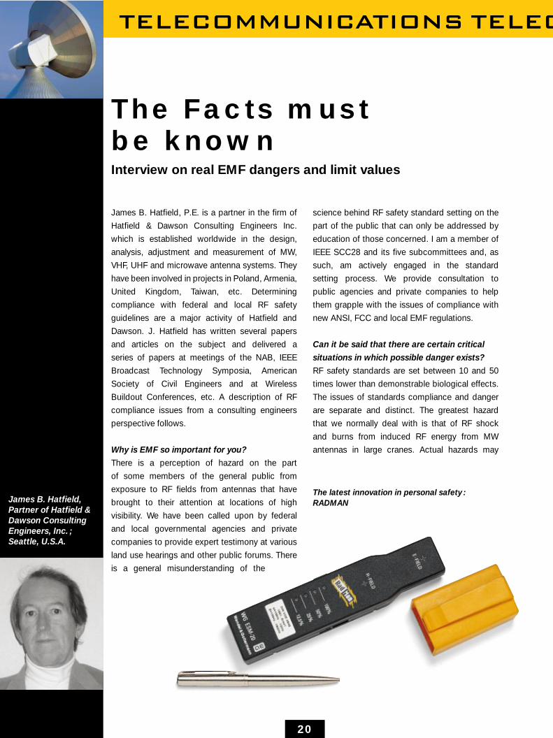
The latest innovation in personal safety :RADMAN

COMMUNICATIONS TELECOMMUNICATI
21
Transmitter tower with various broadcast services
exist in close proximity to broadcast FM and TV
antennas, high power, base insulated LF & MW
towers, RF heat sealers and in the main beam of
high power microwave and radar antennas.
What recommendations would you give
to companies where EMF exposure is a
problem?
The FCC requires licensees of facilities at
antenna farms and other multiple emitter sites to
cooperatively resolve situations where the human
exposure to RF fields exceeds FCC maximum
permissible exposure (MPE) standards. In
complicated situations measurements are
advised. At simpler installations computations
may suffice for the determination of compliance
with the MPE.
What demands do you make of measuring
equipment used for stage 2, pre-qualification?
In an multiple emitter situation where many
different frequencies are radiated a conformal
probe is the only practical solution. The meter
must also respond properly to multiple frequency
fields without exaggerating or minimizing the
measured values. The probe should not have
spurious responses at out of range frequencies. It
is also desirable to have the meter automatically
apply the calibration factor to the readings.
How do you handle situations where regular
over-exposure is likely?
Areas of exceedance must be appropriately
marked and signed. Power may have to be
reduced when towers and other antenna support
structures are climbed. RF protective suits are a
good solution in some situations.
How does Wandel & Goltermann fit into this
environment?
The meter is compact and easy to carry on a trip
in a brief case. The response at MF is the best in
the industry in terms of accurate electric field
readings for AM stations. The magnetic field
meter has a nice dynamic range for determining
compliance with the FCC magnetic field MPE.
The WG meters are well built, light weight, and
easy to operate. O

MILITARY AND TRANSPORT · M
22
Measurement of the Electric Field of a Scanning RadarAntennaUsing the EMR 300 and Probes 8 and 9
Doc. Dr. Dina SimunicUniversity of Zagreb,Faculty of ElectricalEngineering andComputing, Dept. for RadioCommunications and MicrowaveEngineering ;Zagreb, Croatia
F or a long time now, the measurement of
high-frequency pulsed electromagnetic
fields, such as those generated by scan-
ning radar antennas, has been an unresolved
problem. Since radar transmitters predominantly
generate very high peak microwave power, this
type of measurement is of special interest due to
the possible biological effects of such pulses on
humans.
The Dept. for Radio Communications and Micro-
wave Engineering at the University of Zagreb,
Faculty of Electrical Engineering and Computing,
received a request to conduct measurements on
a radar transmitter at Zagreb Airport. The radar in
question is an L-band type (operating frequency
1.3 GHz) used for air-traffic control. Usually,
measurements are carried out when the radar
antenna is stationary (“static case”), which is
advantageous in that it permits the use of
thermocouple detectors, which show a true
rootmean-square (RMS) value. Unfortunately, this
was not possible in this case, as the operation of
the radar could not be interrupted. We decided
not to attempt measurements using detectors
containing thermocouples because of their
sensitivity to temperature fluctuations and to
Field measurements on marine radar

ILITARY AND TRANSPORT · MILITARY A
23
short-term or minor overload.
Moreover, these detectors are too
slow (typical response time 1 s) and
too insensitive to measure rotating
radar pulsed fields at distant
locations. Therefore, our principal task
was to find measuring equipment
capable of performing these measure-
ments.
As the first step, we tried to
characterise the ideal device for
performing such measurements.
The first requirement is certainly an
immediate response (~1 µs or less).
The second prerequisite is that the
peak values of electric fields should
be indicated for dosimetric purposes.
The instruments should therefore have
a high dynamic range (40 dB or a ratio
of 1:100, because the peak electric
field in our case, for example, could
be 33.5 times greater than the RMS
value). The peak values were required
for the purpose of comparison
with standards and guidelines (ENV-
50166-2, IRPA/ICNIRP). The new
European preliminary standard ENV
50166-2: “Human exposure to electro-
magnetic fields – High frequency
(10 kHz to 300 GHz)” (CENELEC,
1995) sets the limit value for pulsed
fields as a peak value of an electric
field strength (V/m). Chapter 5 of the
IRPA/INIRC guidelines, “Guidelines on
limits of exposure to radio-frequency
electromagnetic fields in the frequency
range from 100 kHz to 300 GHz”
(1991) determines the value for a peak
electric field as an equivalent plane
wave field strength averaged over the
pulse width which should not exceed
32 times the field strength limits for
the continuous wave case.
The third characteristic is that of
ensuring a field isotropic response, i.e.
the antenna system should consist of
three dipoles (if measuring an electric
field).
The final property is optional, as it
depends upon the distance from the
source. If the measuring point is in the
near field then both fields – electric
and magnetic – should be measured
isotropically. In this case, the simple
relationship between the electric field,
power density and free space
impedance no longer holds true. Here,
both sensors (for the electric and
magnetic fields) must be small
compared to the wavelength (~λ /10).
Nowadays, most EMF measuring
equipment uses either diodes or
thermocouple detectors. To the best
of our knowledge, diode detectors,
showing the peak value of an electric
field, have not yet been used for
measuring high-peak short pulses.
This is due to the fact that the diode
detector acts as a linear detector at
higher levels: the output voltage is
proportional to the input voltage. This
property, in combination with the
integrated circuits of an instrument,
indicates a value other than the true
RMS and must be corrected using
sensor data.
Finally, measurements could always
be performed using a spectrum
analyzer and a broadband antenna.
Airfield control towerwith radio andradar antennas
P

MILITARY AND TRANSPORT · MILITARY
24
However, this solution is rather incon-
venient.
The solution offered by W&G certainly
represents one of the best on the
market. The EMR-300 with two
electric field probes (types 8 and 9)
has already established itself in the
measurement of continuous-wave
high-frequency fields. Both probes are
based on a diode detector with
integrated circuits. Therefore, in order
to measure the peak values of pulsed
fields, the values displayed by the
instrument have to be compensated.
This is achieved with the aid of
corrective curves. The basis for the
curves is a knowledge of the four
parameters of a radar transmitter:
pulse width, pulse repetition
frequency, aerial rotation speed and
antenna beam width. If these par-
ameters are known, the value
displayed by the instrument can be
scaled to the actual irradiated peak
value of an electric field pulse.
The curves provided by WG have
an abscissa Edisplay and an ordinate
(Epeak/32) / Edisplay (the “beam factor”).
Probe E-display [V/m] Epeak/Edisp Epeak/32 [V/m] Epeak [V/m]
8 0.72 3.37 2.43 77.76
9 0.92 2.65 2.44 78.08
Electric fields measured at a distance of 150 m from the scanning radar antenna in Zagreb, Croatia
Corrective curve of probe type 9 for the radarin Zagreb
Radar Zagreb rotating – probe type 9
0.1 1 10 100
100
10
1
(E-p
eak/
32) /
E-d
isp
lay
E-display
One has to read the value displayed
by the instrument and multiply it by
this “beam factor”. Unfortunately (or
rather, fortunately for me), W&G was
not in possession of such a curve for a
radar with characteristics like ours in
Zagreb (the parameters: PD = 3.3 µs,
PRF = 340 Hz, aerial rotation speed
= 5 rpm and antenna beam width
= 1.2°). Therefore, I accepted a kind
invitation by Mr. Hans Förster, without
whom the EMF group in WG would
9 for the radar in Zagreb (Fig. 1).
Of course, the first thing I did upon my
return to Zagreb was to conduct
measurements on the radar. I
measured the field at a distance of
150 metres from the radar transmitter
station. For the measurements, I used
probe types 8 and 9. The results were
fascinating: even though the displayed
values differed by approximately
28 %, the compensated peak field
values of both probes, with a
not exist, to produce the necessary
curves myself. There, in Eningen,
surrounded by beautiful, peaceful
countryside, I met the whole team
composed of engineering and
marketing geniuses. So, the result of
my enjoyable stay are corrective
curves of the probe types 8 and
difference of approx. 0.4 %, were
almost identical (Table 1).
In conclusion, it appears that the
previously unsolved and complex
problem of measuring electric fields
generated by a scanning radar antenna
has been solved by W&G, who have
provided an almost ideal solution. O
QUALITY QUALITY QUALITY Q
25
Precision for anyPlace in the WorldThe built-in quality of EMF measuring instruments from Wandel & Goltermann
T he measuring instruments from Wandel
& Goltermann for electromagnetic fields
measure with precision, even under
extreme environmental conditions and over long
periods. In this way, they offer a high degree of
measuring accuracy – an indispensable criterion
where the protection of people is concerned.
In order to ensure this high level of quality, the
instruments must undergo stringent tests during
their design and production. Every single circuit
element is tested in-circuit to ensure correct
component insertion, soldering and faultless
operation. Only then is the printed circuit board
released for assembly in the instrument.
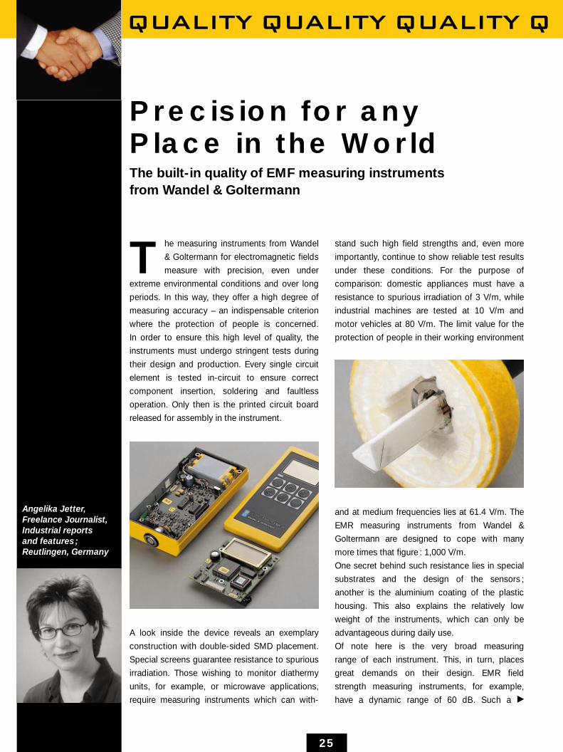
A look inside the device reveals an exemplary
construction with double-sided SMD placement.
Special screens guarantee resistance to spurious
irradiation. Those wishing to monitor diathermy
units, for example, or microwave applications,
require measuring instruments which can with-
stand such high field strengths and, even more
importantly, continue to show reliable test results
under these conditions. For the purpose of
comparison: domestic appliances must have a
resistance to spurious irradiation of 3 V/m, while
industrial machines are tested at 10 V/m and
motor vehicles at 80 V/m. The limit value for the
protection of people in their working environment
and at medium frequencies lies at 61.4 V/m. The
EMR measuring instruments from Wandel &
Goltermann are designed to cope with many
more times that figure : 1,000 V/m.
One secret behind such resistance lies in special
substrates and the design of the sensors ;
another is the aluminium coating of the plastic
housing. This also explains the relatively low
weight of the instruments, which can only be
advantageous during daily use.
Of note here is the very broad measuring
range of each instrument. This, in turn, places
great demands on their design. EMR field
strength measuring instruments, for example,
have a dynamic range of 60 dB. Such a
Angelika Jetter,Freelance Journalist,Industrial reports and features ;Reutlingen, Germany
P
QUALITY QUALITY QUALITY QUALITY
26
scope is currently unmatched (Burn-in
diagram).
The burn-in process to which every
instrument must be subjected has a
passive and an active phase. During
the passive phase, an increased
outside temperature is simulated. In
the active phase, this is joined by
the heating up of the switched-on
unit with raised temperatures in the
interior.
The device remains in the burn-in
chamber for several days, and is
exposed in cycles to different ambient
temperatures: 20 hours at + 50 °C and
4 hours at + 23 °C.
The above process pre-empts the
failure rate of the first year and is
equivalent to running in an engine.
After burn-in, the test results are more
constant. And the instrument must
only be calibrated after the relatively
long period of two years. For the user,
the instrument therefore has the
advantage of high availability coupled
with low running costs.
In order to ensure quality, the
measuring instruments are not only
exposed to heat. Environmental tests
anticipate extreme situations such as
those which occur after changing from
warm rooms to a cold outdoor
environment. The devices are stored
at temperatures of –40°C and +70°C
and then undergo a function test.
During operation, they must withstand
temperatures ranging from 0 °C to
+ 50 °C, which means that they must
display accurate results under these
conditions. The humidity test entails
96 hours of exposure to + 40 °C and
95 % air humidity, which is equivalent
to the climate in a tropical rain forest.
Only then is a measuring instrument
from Wandel & Goltermann sent on its
way to the customer. It is fully
equipped to cope with the stresses of
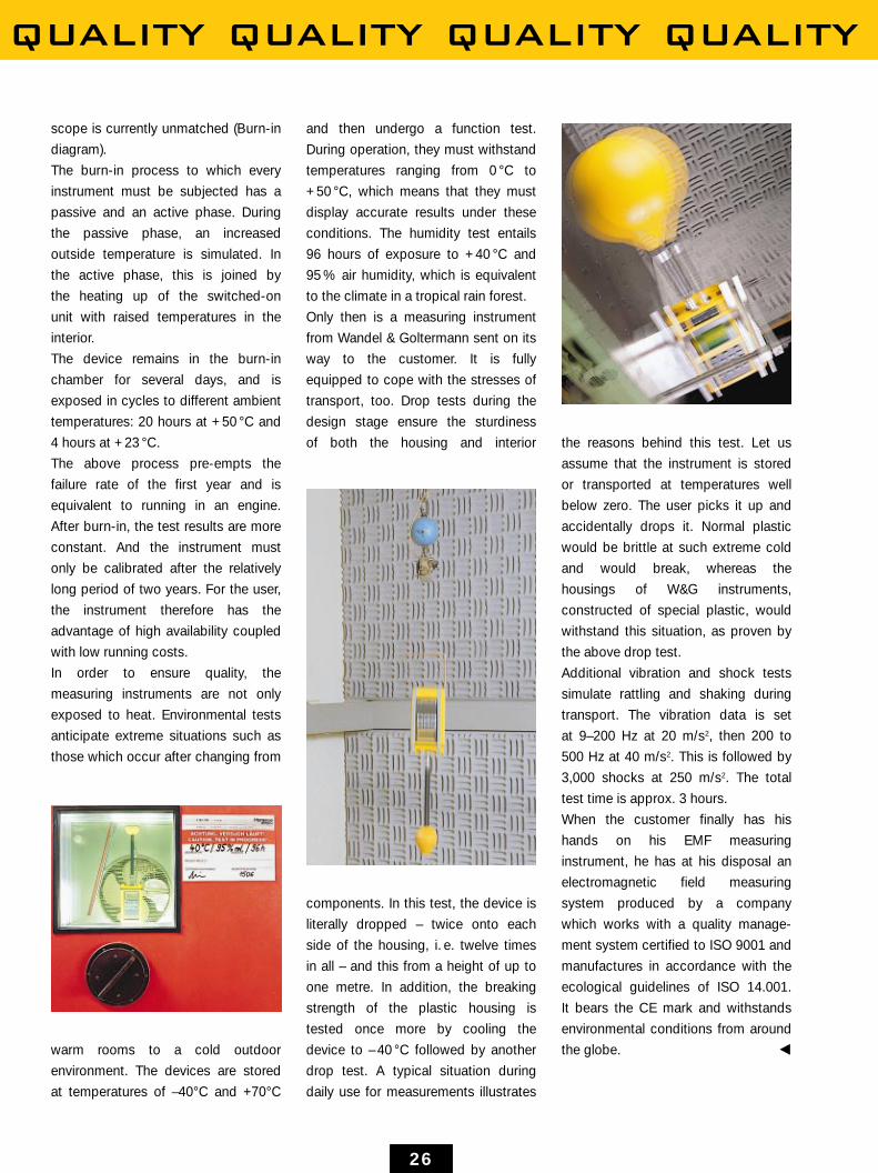
transport, too. Drop tests during the
design stage ensure the sturdiness
of both the housing and interior
components. In this test, the device is
literally dropped – twice onto each
side of the housing, i. e. twelve times
in all – and this from a height of up to
one metre. In addition, the breaking
strength of the plastic housing is
tested once more by cooling the
device to – 40 °C followed by another
drop test. A typical situation during
daily use for measurements illustrates
the reasons behind this test. Let us
assume that the instrument is stored
or transported at temperatures well
below zero. The user picks it up and
accidentally drops it. Normal plastic
would be brittle at such extreme cold
and would break, whereas the
housings of W&G instruments,
constructed of special plastic, would
withstand this situation, as proven by
the above drop test.
Additional vibration and shock tests
simulate rattling and shaking during
transport. The vibration data is set
at 9–200 Hz at 20 m/s2, then 200 to
500 Hz at 40 m/s2. This is followed by
3,000 shocks at 250 m/s2. The total
test time is approx. 3 hours.
When the customer finally has his
hands on his EMF measuring
instrument, he has at his disposal an
electromagnetic field measuring
system produced by a company
which works with a quality manage-
ment system certified to ISO 9001 and
manufactures in accordance with the
ecological guidelines of ISO 14.001.
It bears the CE mark and withstands
environmental conditions from around
the globe. O

Wandel & Goltermann GmbH&Co.Elektronische MeßtechnikMühleweg 5D-72800 Eningen u.A.Tel.: +49 71 21 / 86-1616Fax: +49 71 21 / 86-1332email: [email protected]://www.wg.comOrder no. 12.97/WG1/210/5Subject to change