noise-induced dephasing in neutron interferometry
TRANSCRIPT

PHYSICAL REVIEW A 81, 053609 (2010)
Noise-induced dephasing in neutron interferometry
G. Sulyok,1 Y. Hasegawa,1 J. Klepp,2 H. Lemmel,1,3 and H. Rauch1
1Atominstitut, Technische Universitat Wien, 1020 Vienna, Austria2Faculty of Physics, University of Vienna, 1090 Vienna, Austria
3Institut Laue-Langevin, F-38042 Grenoble, France(Received 26 February 2010; published 11 May 2010)
Decoherence phenomenona in a neutron interferometer are analyzed by simulation of the effects of anenvironment with magnetic noise fields. Basic calculations and experiments show the validity and limitationsof this model system. In particular, loss and recovery of the interference pattern with controllable noise sourcesin both interferometer arms are discussed in detail. In addition, the decoherence behavior at high interferenceorder, where Schrodinger-cat-like states exist in the interferometer, is investigated. While at low interferenceorder a smearing of the interference pattern is observed, at high interference order a smearing of the modulatedmomentum distribution occurs.
DOI: 10.1103/PhysRevA.81.053609 PACS number(s): 03.75.Dg, 03.65.Yz, 42.50.−p
I. INTRODUCTION
Interferometers of different types have become standardtools for the demonstration of wave properties of massiveparticles, underlining the validity of quantum mechanicsfor particles like electrons [1,2] or neutrons [3], and evenfor atoms and molecules with high mass numbers [4,5].Apart from imperfections of the whole interferometer setup,observation of interference properties is complicated becauseof decoherence effects caused by the environment. The theoryof open quantum systems [6–9] provides explanations forthe associated loss of coherence. The interaction between theobserved system and the environment causes their entangle-ment and destroys the unitary evolution of the system and itsquantum behavior. Experimental observations of decoherenceprocesses have been reported, for example, with electronscoupling to an electron gas inside a semiconducting plate [10],with molecules colliding with background gases [11], and withmolecules decohering by thermal emission of radiation [12].A profound understanding of these decoherence phenomenaalso leads to a deeper understanding of the transition betweenthe quantum regime and the classical world. In this context,Stern et al. [13] have proved that the loss of coherence can alsobe described by statistically distributed phase accumulationsof the interfering waves.
In the case of neutrons, these phases can be causedby the magnetic dipole interaction described by theZeeman-Hamiltonian H = −µ�σ · �B. During their flightthrough the field region, the neutrons accumulate a phase givenby φ = (µ/h)�σ · ∫ �Bdt . In our experiments, the phase derivesfrom a classical noise field that is time dependent and causesenergy exchange in the form of photon absorption or emission,as calculated and measured by Summhammer and co-workers[14,15]. Since the states of the magnetic field do not change inthe photon exchange process, there is no entanglement betweenthe neutron and the field, but the effects of the statisticallydistributed phase shifts on the observed interference patternare equivalent to the effects of a quantum-mechanicalenvironment [13]. For a more detailed description ofthe connection between noise fields and decoherenceeffects in the framework of Lindblad master equations,see [16].
We investigate the dephasing effect as a function of thestrength of the Gaussian noise field, which shows the responseto the dynamical quantum phase. The geometrical phaseremains unchanged since the field acts along the same directionand no area is enclosed owing to the excursion in parameterspace. A study of the stability of the geometrical phase andits contribution to the dephasing process has been publishedrecently [17].
Another prediction of decoherence theory concerns macro-scopically distinguishable states (so-called Schrodinger-cat-like states) whose sensitivity to external fluctuations increaseswhen their spatial separation increases [8,18]. In the neutroninterferometer, these states can be produced by thick phaseshifters, when the phase shifts become larger than the coher-ence lengths [19,20].
The work presented is organized as follows. In Sec. II,basic formulas are developed for calculating the interfer-ometer contrast when magnetic noise fields are applied inthe interferometer. Section III A focuses on the experimentalresults for the standard interferometric setup (phase contrastmeasurements). Contrast behavior for a noise field withdifferent frequency bandwidths is investigated. Further, fornoise fields applied in each interferometer arm, both thecases of correlated and uncorrelated signals are discussed.In Sec. III B, the preparation of Schrodinger-cat-like states inthe neutron interferometer and their properties are explained.These states are then exposed to magnetic noise and the effecton the arising momentum modulation is examined.
II. THEORY
Before addressing the actual experiments, we briefly reviewthe connection between the measured interferometer contrastand the neutron state. Following the density-matrix approach[21], we write the incoming state as
ρin = |0〉〈0| ⊗ ρspin =(
1 0
0 0
)⊗ ρspin. (1)
For the path degree of freedom, there are only two possiblestates, namely, |0〉 (denoting the direction of the incomingO beam) and |1〉 (denoting the direction of the reflected
1050-2947/2010/81(5)/053609(8) 053609-1 ©2010 The American Physical Society
SULYOK, HASEGAWA, KLEPP, LEMMEL, AND RAUCH PHYSICAL REVIEW A 81, 053609 (2010)
PSBS M BS
U1 O-Beam
H-Beam
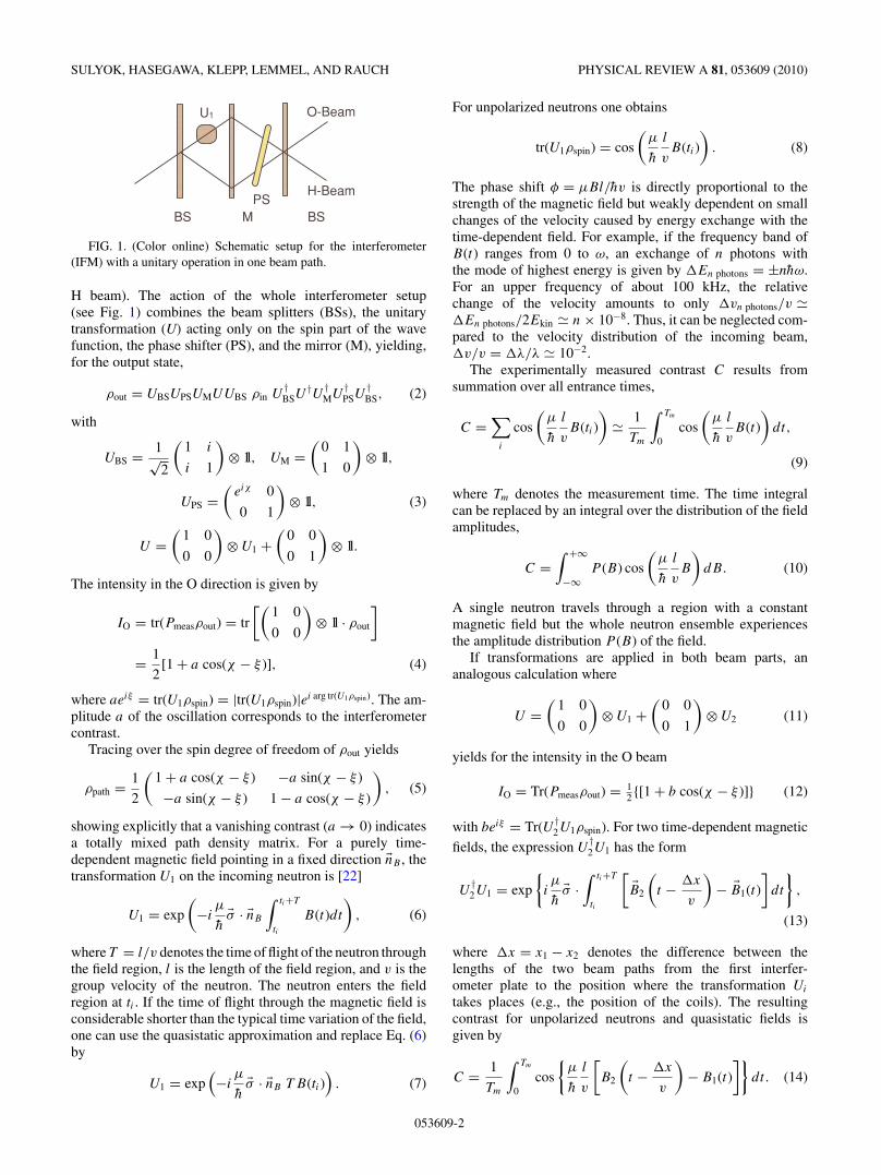
FIG. 1. (Color online) Schematic setup for the interferometer(IFM) with a unitary operation in one beam path.
H beam). The action of the whole interferometer setup(see Fig. 1) combines the beam splitters (BSs), the unitarytransformation (U) acting only on the spin part of the wavefunction, the phase shifter (PS), and the mirror (M), yielding,for the output state,
ρout = UBSUPSUMUUBS ρin U†BSU
†U †MU
†PSU
†BS, (2)
with
UBS = 1√2
(1 i
i 1
)⊗ 1l, UM =
(0 1
1 0
)⊗ 1l,
UPS =(
eiχ 0
0 1
)⊗ 1l, (3)
U =(
1 0
0 0
)⊗ U1 +
(0 0
0 1
)⊗ 1l.
The intensity in the O direction is given by
IO = tr(Pmeasρout) = tr
[(1 0
0 0
)⊗ 1l · ρout
]
= 1
2[1 + a cos(χ − ξ )], (4)
where aeiξ = tr(U1ρspin) = |tr(U1ρspin)|ei arg tr(U1ρspin). The am-plitude a of the oscillation corresponds to the interferometercontrast.
Tracing over the spin degree of freedom of ρout yields
ρpath = 1
2
(1 + a cos(χ − ξ ) −a sin(χ − ξ )
−a sin(χ − ξ ) 1 − a cos(χ − ξ )
), (5)
showing explicitly that a vanishing contrast (a → 0) indicatesa totally mixed path density matrix. For a purely time-dependent magnetic field pointing in a fixed direction �nB , thetransformation U1 on the incoming neutron is [22]
U1 = exp
(−i
µ
h�σ · �nB
∫ ti+T
ti
B(t)dt
), (6)
where T = l/v denotes the time of flight of the neutron throughthe field region, l is the length of the field region, and v is thegroup velocity of the neutron. The neutron enters the fieldregion at ti . If the time of flight through the magnetic field isconsiderable shorter than the typical time variation of the field,one can use the quasistatic approximation and replace Eq. (6)by
U1 = exp(−i
µ
h�σ · �nB T B(ti)
). (7)
For unpolarized neutrons one obtains
tr(U1ρspin) = cos
(µ
h
l
vB(ti)
). (8)
The phase shift φ = µBl/hv is directly proportional to thestrength of the magnetic field but weakly dependent on smallchanges of the velocity caused by energy exchange with thetime-dependent field. For example, if the frequency band ofB(t) ranges from 0 to ω, an exchange of n photons withthe mode of highest energy is given by �En photons = ±nhω.For an upper frequency of about 100 kHz, the relativechange of the velocity amounts to only �vn photons/v ��En photons/2Ekin � n × 10−8. Thus, it can be neglected com-pared to the velocity distribution of the incoming beam,�v/v = �λ/λ � 10−2.
The experimentally measured contrast C results fromsummation over all entrance times,
C =∑
i
cos
(µ
h
l
vB(ti)
)� 1
Tm
∫ Tm
0cos
(µ
h
l
vB(t)
)dt,
(9)
where Tm denotes the measurement time. The time integralcan be replaced by an integral over the distribution of the fieldamplitudes,
C =∫ +∞
−∞P (B) cos
(µ
h
l
vB
)dB. (10)
A single neutron travels through a region with a constantmagnetic field but the whole neutron ensemble experiencesthe amplitude distribution P (B) of the field.
If transformations are applied in both beam parts, ananalogous calculation where
U =(
1 0
0 0
)⊗ U1 +
(0 0
0 1
)⊗ U2 (11)
yields for the intensity in the O beam
IO = Tr(Pmeasρout) = 12 {[1 + b cos(χ − ξ )]} (12)
with beiξ = Tr(U †2U1ρspin). For two time-dependent magnetic
fields, the expression U†2U1 has the form
U†2U1 = exp
{iµ
h�σ ·
∫ ti+T
ti
[�B2
(t − �x
v
)− �B1(t)
]dt
},
(13)
where �x = x1 − x2 denotes the difference between thelengths of the two beam paths from the first interfer-ometer plate to the position where the transformation Ui
takes places (e.g., the position of the coils). The resultingcontrast for unpolarized neutrons and quasistatic fields isgiven by
C = 1
Tm
∫ Tm
0cos
{µ
h
l
v
[B2
(t − �x
v
)− B1(t)
]}dt. (14)
053609-2
NOISE-INDUCED DEPHASING IN NEUTRON INTERFEROMETRY PHYSICAL REVIEW A 81, 053609 (2010)
noise coil
phase shifter
O-Detector
H-Detector
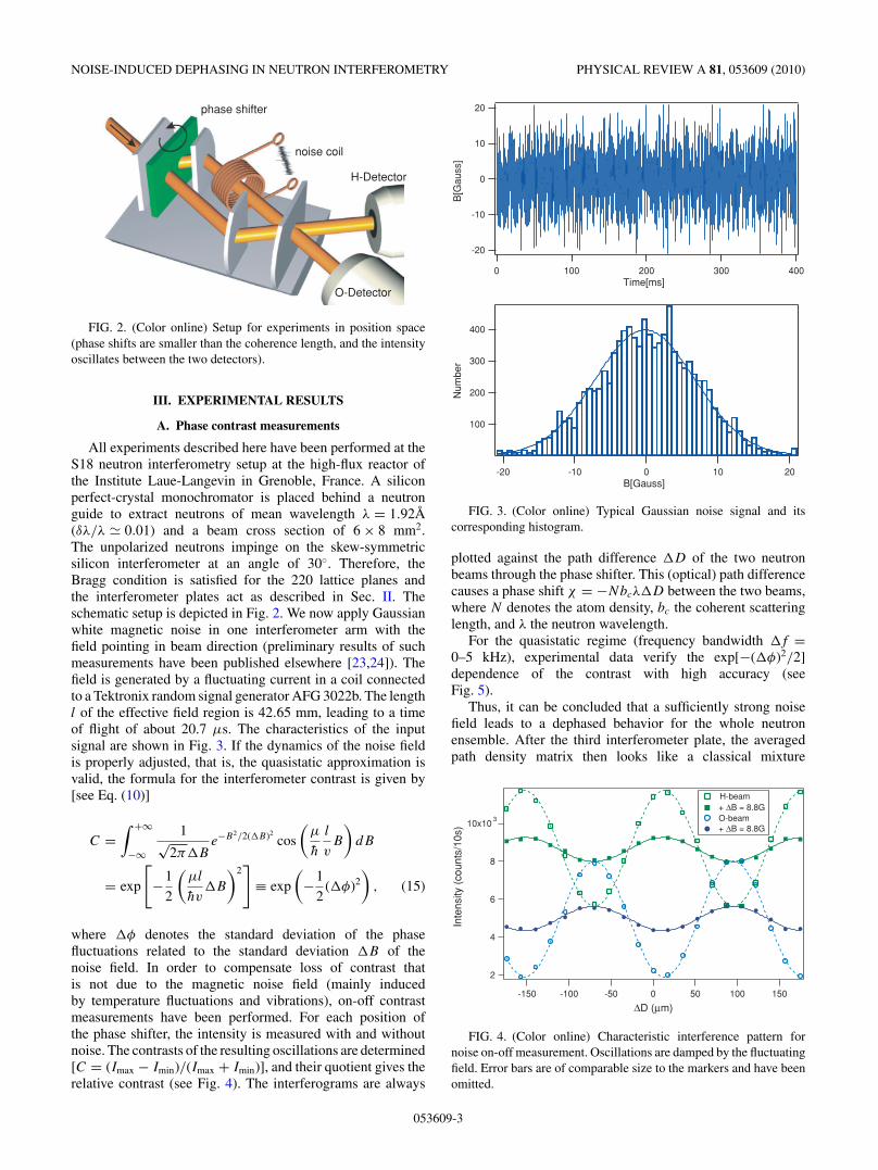
FIG. 2. (Color online) Setup for experiments in position space(phase shifts are smaller than the coherence length, and the intensityoscillates between the two detectors).
III. EXPERIMENTAL RESULTS
A. Phase contrast measurements
All experiments described here have been performed at theS18 neutron interferometry setup at the high-flux reactor ofthe Institute Laue-Langevin in Grenoble, France. A siliconperfect-crystal monochromator is placed behind a neutronguide to extract neutrons of mean wavelength λ = 1.92A(δλ/λ � 0.01) and a beam cross section of 6 × 8 mm2.The unpolarized neutrons impinge on the skew-symmetricsilicon interferometer at an angle of 30◦. Therefore, theBragg condition is satisfied for the 220 lattice planes andthe interferometer plates act as described in Sec. II. Theschematic setup is depicted in Fig. 2. We now apply Gaussianwhite magnetic noise in one interferometer arm with thefield pointing in beam direction (preliminary results of suchmeasurements have been published elsewhere [23,24]). Thefield is generated by a fluctuating current in a coil connectedto a Tektronix random signal generator AFG 3022b. The lengthl of the effective field region is 42.65 mm, leading to a timeof flight of about 20.7 µs. The characteristics of the inputsignal are shown in Fig. 3. If the dynamics of the noise fieldis properly adjusted, that is, the quasistatic approximation isvalid, the formula for the interferometer contrast is given by[see Eq. (10)]
C =∫ +∞
−∞
1√2π�B
e−B2/2(�B)2cos
(µ
h
l
vB
)dB
= exp
[−1
2
(µl
hv�B
)2]
≡ exp
(−1
2(�φ)2
), (15)
where �φ denotes the standard deviation of the phasefluctuations related to the standard deviation �B of thenoise field. In order to compensate loss of contrast thatis not due to the magnetic noise field (mainly inducedby temperature fluctuations and vibrations), on-off contrastmeasurements have been performed. For each position ofthe phase shifter, the intensity is measured with and withoutnoise. The contrasts of the resulting oscillations are determined[C = (Imax − Imin)/(Imax + Imin)], and their quotient gives therelative contrast (see Fig. 4). The interferograms are always
-20
-10
0
10
20
B[G
auss
]
4003002001000Time[ms]
400
300
200
100
Num
ber
20100-10-20B[Gauss]
FIG. 3. (Color online) Typical Gaussian noise signal and itscorresponding histogram.
plotted against the path difference �D of the two neutronbeams through the phase shifter. This (optical) path differencecauses a phase shift χ = −Nbcλ�D between the two beams,where N denotes the atom density, bc the coherent scatteringlength, and λ the neutron wavelength.
For the quasistatic regime (frequency bandwidth �f =0–5 kHz), experimental data verify the exp[−(�φ)2/2]dependence of the contrast with high accuracy (seeFig. 5).
Thus, it can be concluded that a sufficiently strong noisefield leads to a dephased behavior for the whole neutronensemble. After the third interferometer plate, the averagedpath density matrix then looks like a classical mixture
10x103
8
6
4
2
Inte
nsity
(co
unts
/10s
)
150100500-50-100-150
∆D (µm)
H-beam + ∆B = 8.8G O-beam + ∆B = 8.8G
FIG. 4. (Color online) Characteristic interference pattern fornoise on-off measurement. Oscillations are damped by the fluctuatingfield. Error bars are of comparable size to the markers and have beenomitted.
053609-3

SULYOK, HASEGAWA, KLEPP, LEMMEL, AND RAUCH PHYSICAL REVIEW A 81, 053609 (2010)
1.0
0.8
0.6
0.4
0.2
Rel
ativ
e C
ontr
ast
20151050∆ B [G]
0-5kHz
0-20kHz
0-40kHz
20-40kHz
40-60kHz
FIG. 5. (Color online) Loss of contrast as a function ofthe standard deviation of the Gaussian-distributed field ampli-tudes caused by magnetic noise with different frequency band-widths �f . The dashed lines are exponential fits whereasthe solid line represents the theory curve in the quasistaticregime. Error bars of comparable size to the markers have beenomitted.
since the intensity no longer oscillates between the O andH detectors:
ρpath = 1
2
(1 + e−(�φ)2/2 cos χ −e−(�φ)2/2 sin χ
−e−(�φ)2/2 sin χ 1 − e−(�φ)2/2 cos χ
)
→ 1
2
(1 0
0 1
). (16)
Note that this (nonunitary) evolution of the neutron path stateis an effective realization of a Lindblad master equation [25]with a single dissipator term �,
ρ = − i
h[H,ρ] + �†ρ� − 1
2(�†�ρ + ρ�†�). (17)
Now we choose the Hamiltonian to be H = (α/2)σy and theLindblad operator to be � = √
λ/2σy acting on the system fora time τ . For the initial state ρ(0) = |0〉〈0|, one obtains in the(|0〉,|1〉) basis (the eigenstates of σz)
ρ(τ ) = 1
2
(1 + e−λτ cos ατ −e−λτ sin ατ
−e−λτ sin ατ 1 − e−λτ cos ατ
). (18)
If we identify the rotation angle ατ with the angle χ andthe damping factor λτ with (�φ)2/2, the correspondence ofEqs. (16) and (17) is clearly visible. A similar approach canbe found in [16].
If the frequency bandwidth of the noise signal is enlarged,the quasistatic approximation is no longer valid, and the expo-nential decay is weakened, C = exp[−γ (�φ)2/2], describedby a fit parameter γ < 1 (see Fig. 5). A detailed analysis ofthe frequency dependence of γ = γ (�f ) will be treated in aforthcoming presentation.
It should be kept in mind that, in a time-resolved measure-ment, the interference pattern could, in principle, be restored.The loss of contrast can also be reversed when the same noisesignal is applied in the second beam path. This can be achievedwith an identical second coil driven by the same current (see
noise coil 1
noise coil 2
phase shifter
O-Detector
H-Detector
FIG. 6. (Color online) Experimental setup with two coils.
Fig. 6). If the positions of the two coils in the interferometerare not symmetric, an additional time delay �t has to beimplemented to compensate for the position difference �x.Equation (14) then becomes [φi = (µ/h)(l/v)Bi]
C = 1
Tm
∫ Tm
0cos
[φ2
(t + �t − �x
v
)− φ1(t)
]dt. (19)
For identical, synchronized noise signals (φ1 = φ2 =φ and �t = �x/v), recovery of full contrast can beachieved (C = 1) and has been experimentally verified (seeFig. 7).
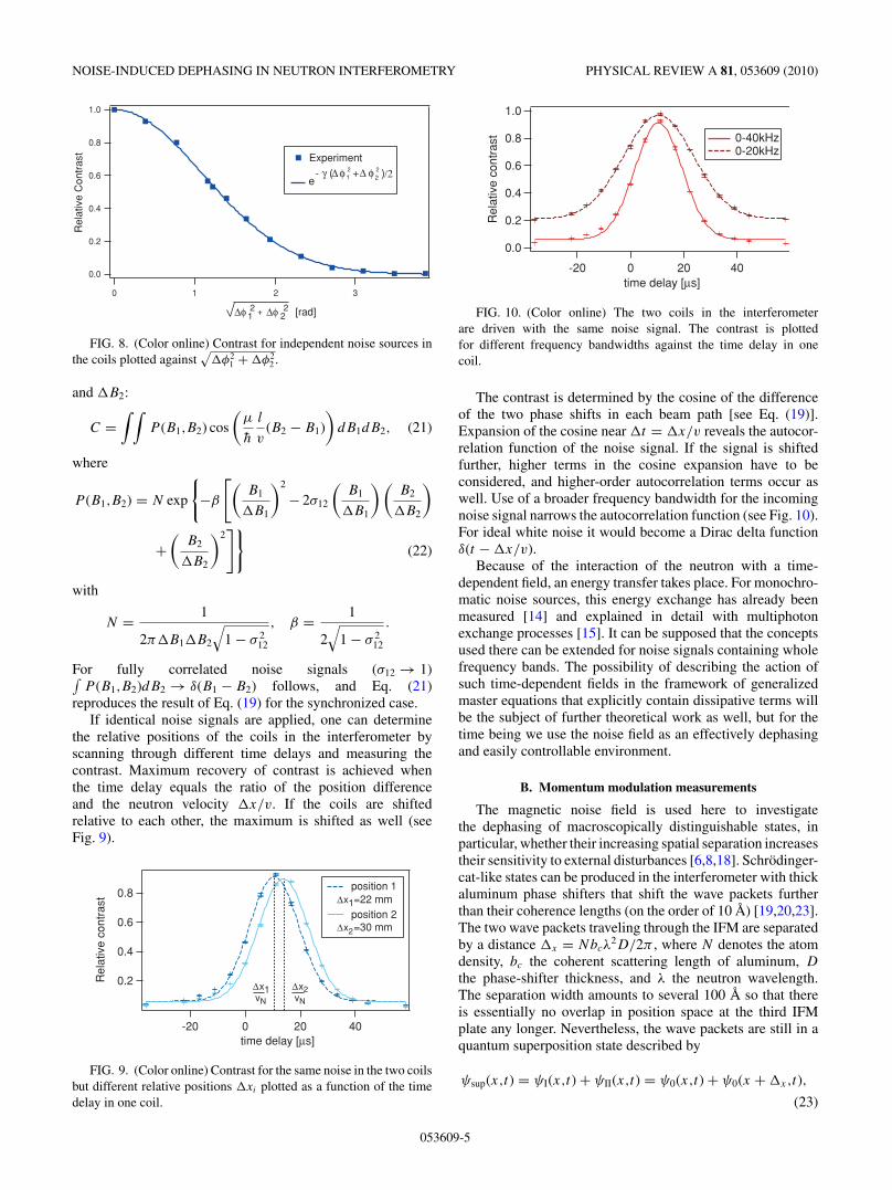
For identical, unsynchronized noise, or two completelydifferent noise signals, the dephasing process is enforced.For different signals with the same frequency band-width �f , the e−γ (�φi )2/2 factors of the two Gaussiannoise fields contribute multiplicatively to the contrast (seeFig. 8),
C = exp(− 1
2γ [(�φ1)2 + (�φ2)2]). (20)
In the quasistatic case (γ = 1), this formula results fromaveraging over an uncorrelated two-dimensional Gaussiandistribution for B1 and B2 with mean values B0
1 = B02 = 0,
correlation coefficient σ12 = 0, and standard deviations �B1
12x103
10
8
6
4
2
Inte
nsity
(co
unts
/10s
ec)
150100500-50-100-150 ∆D[µm]
H-beam + ∆B = 7G O-beam + ∆B = 7G
FIG. 7. (Color online) Interferogram for identical synchro-nized noise in both arms. Contrast remains when noise isturned on.
053609-4
NOISE-INDUCED DEPHASING IN NEUTRON INTERFEROMETRY PHYSICAL REVIEW A 81, 053609 (2010)
1.0
0.8
0.6
0.4
0.2
0.0
Rel
ativ
e C
ontr
ast
3210
∆φ
Experiment
∆φ12
22+ [rad]
eφ ∆ 1
2 + ∆ φ 22- γ ( )/2
FIG. 8. (Color online) Contrast for independent noise sources inthe coils plotted against
√�φ2
1 + �φ22 .
and �B2:
C =∫ ∫
P (B1,B2) cos
(µ
h
l
v(B2 − B1)
)dB1dB2, (21)
where
P (B1,B2) = N exp
{−β
[(B1
�B1
)2
− 2σ12
(B1
�B1
)(B2
�B2
)
+(
B2
�B2
)2]}
(22)
with
N = 1
2π�B1�B2
√1 − σ 2
12
, β = 1
2√
1 − σ 212
.
For fully correlated noise signals (σ12 → 1)∫P (B1,B2)dB2 → δ(B1 − B2) follows, and Eq. (21)
reproduces the result of Eq. (19) for the synchronized case.If identical noise signals are applied, one can determine
the relative positions of the coils in the interferometer byscanning through different time delays and measuring thecontrast. Maximum recovery of contrast is achieved whenthe time delay equals the ratio of the position differenceand the neutron velocity �x/v. If the coils are shiftedrelative to each other, the maximum is shifted as well (seeFig. 9).
0.8
0.6
0.4
0.2Rel
ativ
e co
ntra
st
40200-20 time delay [µs]
position 1
position 2
x1∆vN
x∆vN
2
x1∆ =22 mm
x∆ =30 mm2
FIG. 9. (Color online) Contrast for the same noise in the two coilsbut different relative positions �xi plotted as a function of the timedelay in one coil.
1.0
0.8
0.6
0.4
0.2
0.0
Rel
ativ
e co
ntra
st
40200-20 time delay [µs]
0-40kHz 0-20kHz
FIG. 10. (Color online) The two coils in the interferometerare driven with the same noise signal. The contrast is plottedfor different frequency bandwidths against the time delay in onecoil.
The contrast is determined by the cosine of the differenceof the two phase shifts in each beam path [see Eq. (19)].Expansion of the cosine near �t = �x/v reveals the autocor-relation function of the noise signal. If the signal is shiftedfurther, higher terms in the cosine expansion have to beconsidered, and higher-order autocorrelation terms occur aswell. Use of a broader frequency bandwidth for the incomingnoise signal narrows the autocorrelation function (see Fig. 10).For ideal white noise it would become a Dirac delta functionδ(t − �x/v).
Because of the interaction of the neutron with a time-dependent field, an energy transfer takes place. For monochro-matic noise sources, this energy exchange has already beenmeasured [14] and explained in detail with multiphotonexchange processes [15]. It can be supposed that the conceptsused there can be extended for noise signals containing wholefrequency bands. The possibility of describing the action ofsuch time-dependent fields in the framework of generalizedmaster equations that explicitly contain dissipative terms willbe the subject of further theoretical work as well, but for thetime being we use the noise field as an effectively dephasingand easily controllable environment.
B. Momentum modulation measurements
The magnetic noise field is used here to investigatethe dephasing of macroscopically distinguishable states, inparticular, whether their increasing spatial separation increasestheir sensitivity to external disturbances [6,8,18]. Schrodinger-cat-like states can be produced in the interferometer with thickaluminum phase shifters that shift the wave packets furtherthan their coherence lengths (on the order of 10 A) [19,20,23].The two wave packets traveling through the IFM are separatedby a distance �x = Nbcλ
2D/2π , where N denotes the atomdensity, bc the coherent scattering length of aluminum, D
the phase-shifter thickness, and λ the neutron wavelength.The separation width amounts to several 100 A so that thereis essentially no overlap in position space at the third IFMplate any longer. Nevertheless, the wave packets are still in aquantum superposition state described by
ψsup(x,t) = ψI(x,t) + ψII(x,t) = ψ0(x,t) + ψ0(x + �x,t),
(23)
053609-5
SULYOK, HASEGAWA, KLEPP, LEMMEL, AND RAUCH PHYSICAL REVIEW A 81, 053609 (2010)
x∆
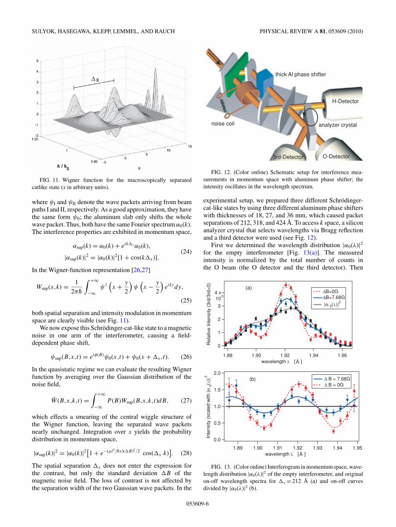
FIG. 11. Wigner function for the macroscopically separatedcatlike state (x in arbitrary units).
where ψI and ψII denote the wave packets arriving from beampaths I and II, respectively. As a good approximation, they havethe same form ψ0; the aluminum slab only shifts the wholewave packet. Thus, both have the same Fourier spectrum α0(k).The interference properties are exhibited in momentum space,
αsup(k) = α0(k) + eik�x α0(k),(24)
|αsup(k)|2 = |α0(k)|2[1 + cos(k�x)].
In the Wigner-function representation [26,27]
Wsup(x,k) = 1
2πh
∫ +∞
−∞ψ†
(x + y
2
)ψ
(x − y
2
)eikydy,
(25)
both spatial separation and intensity modulation in momentumspace are clearly visible (see Fig. 11).
We now expose this Schrodinger-cat-like state to a magneticnoise in one arm of the interferometer, causing a field-dependent phase shift,
ψsup(B,x,t) = eiφ(B)ψ0(x,t) + ψ0(x + �x,t). (26)
In the quasistatic regime we can evaluate the resulting Wignerfunction by averaging over the Gaussian distribution of thenoise field,
W (B,x,k,t) =∫ +∞
−∞P (B)Wsup(B,x,k,t)dB, (27)
which effects a smearing of the central wiggle structure ofthe Wigner function, leaving the separated wave packetsnearly unchanged. Integration over x yields the probabilitydistribution in momentum space,
|αsup(k)|2 = |α0(k)|2[1 + e−(µl2/hv)(�B)2/2 cos(�x k)]. (28)
The spatial separation �x does not enter the expression forthe contrast, but only the standard deviation �B of themagnetic noise field. The loss of contrast is not affected bythe separation width of the two Gaussian wave packets. In the
thick Al phase shifter
H-Detector
O-Detector3rd-Detector
noise coil analyzer crystal
FIG. 12. (Color online) Schematic setup for interference mea-surements in momentum space with aluminum phase shifter; theintensity oscillates in the wavelength spectrum.
experimental setup, we prepared three different Schrodinger-cat-like states by using three different aluminum phase shifterswith thicknesses of 18, 27, and 36 mm, which caused packetseparations of 212, 318, and 424 A. To access k space, a siliconanalyzer crystal that selects wavelengths via Bragg reflectionand a third detector were used (see Fig. 12).
First we determined the wavelength distribution |α0(λ)|2for the empty interferometer [Fig. 13(a)]. The measuredintensity is normalized by the total number of counts inthe O beam (the O detector and the third detector). Then
4 x-3
3
2
1
0 Rel
ativ
e In
tens
ity (
3rd/
3rd+
0)
1.961.941.921.901.88wavelength λ [ ]
∆B=0G∆B=7.68G |α 0(λ)|
2 10
(a)
Å
2.0
1.5
1.0
0.5
0.0
Inte
nsity
(sc
aled
with
|α 0(
λ)|2
1.951.941.931.921.911.901.89wavelength λ [ ]
∆ B = 7.68G ∆ B = 0G
(b)
Å
FIG. 13. (Color online) Interferogram in momentum space, wave-length distribution |α0(λ)|2 of the empty interferometer, and originalon-off wavelength spectra for �x = 212 A (a) and on-off curvesdivided by |α0(λ)|2 (b).
053609-6
NOISE-INDUCED DEPHASING IN NEUTRON INTERFEROMETRY PHYSICAL REVIEW A 81, 053609 (2010)
1.0
0.8
0.6
0.4
0.2
0.0
Rel
ativ
e C
ontr
ast
121086420 ∆B[Gauss]
∆x = 212 Å
∆x = 318 Å
∆x = 424 Å
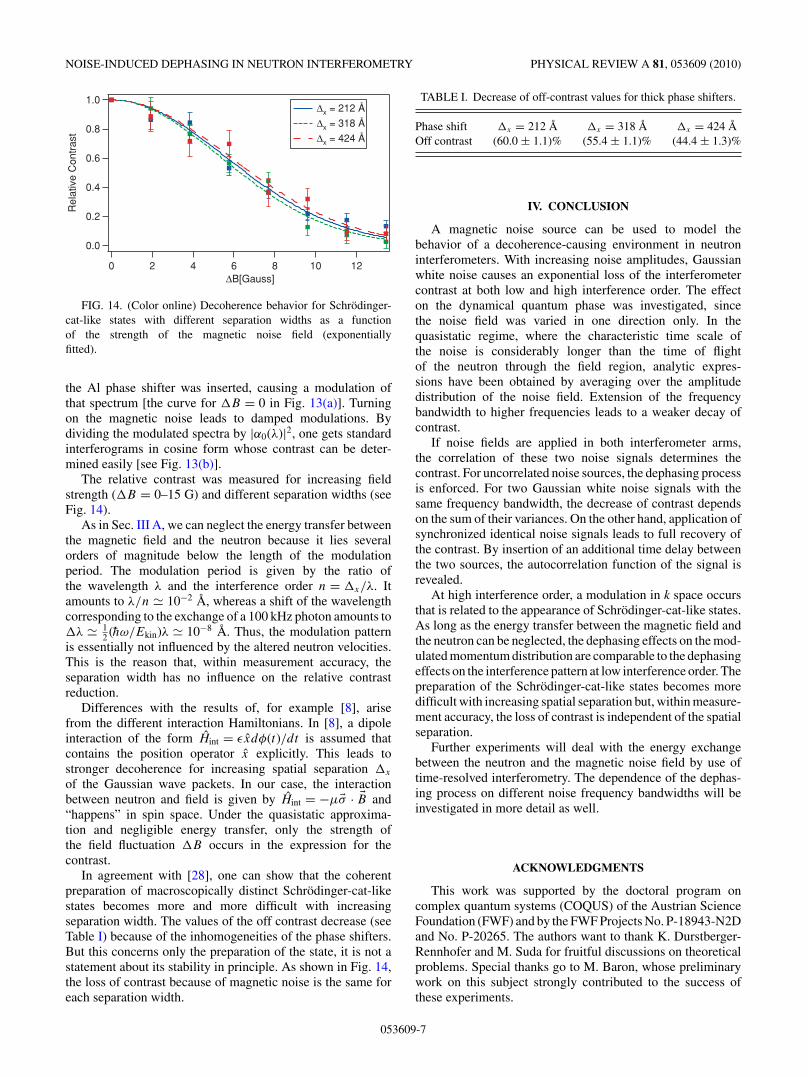
FIG. 14. (Color online) Decoherence behavior for Schrodinger-cat-like states with different separation widths as a functionof the strength of the magnetic noise field (exponentiallyfitted).
the Al phase shifter was inserted, causing a modulation ofthat spectrum [the curve for �B = 0 in Fig. 13(a)]. Turningon the magnetic noise leads to damped modulations. Bydividing the modulated spectra by |α0(λ)|2, one gets standardinterferograms in cosine form whose contrast can be deter-mined easily [see Fig. 13(b)].
The relative contrast was measured for increasing fieldstrength (�B = 0–15 G) and different separation widths (seeFig. 14).
As in Sec. III A, we can neglect the energy transfer betweenthe magnetic field and the neutron because it lies severalorders of magnitude below the length of the modulationperiod. The modulation period is given by the ratio ofthe wavelength λ and the interference order n = �x/λ. Itamounts to λ/n � 10−2 A, whereas a shift of the wavelengthcorresponding to the exchange of a 100 kHz photon amounts to�λ � 1
2 (hω/Ekin)λ � 10−8 A. Thus, the modulation patternis essentially not influenced by the altered neutron velocities.This is the reason that, within measurement accuracy, theseparation width has no influence on the relative contrastreduction.
Differences with the results of, for example [8], arisefrom the different interaction Hamiltonians. In [8], a dipoleinteraction of the form Hint = εxdφ(t)/dt is assumed thatcontains the position operator x explicitly. This leads tostronger decoherence for increasing spatial separation �x
of the Gaussian wave packets. In our case, the interactionbetween neutron and field is given by Hint = −µ�σ · �B and“happens” in spin space. Under the quasistatic approxima-tion and negligible energy transfer, only the strength ofthe field fluctuation �B occurs in the expression for thecontrast.
In agreement with [28], one can show that the coherentpreparation of macroscopically distinct Schrodinger-cat-likestates becomes more and more difficult with increasingseparation width. The values of the off contrast decrease (seeTable I) because of the inhomogeneities of the phase shifters.But this concerns only the preparation of the state, it is not astatement about its stability in principle. As shown in Fig. 14,the loss of contrast because of magnetic noise is the same foreach separation width.
TABLE I. Decrease of off-contrast values for thick phase shifters.
Phase shift �x = 212 A �x = 318 A �x = 424 AOff contrast (60.0 ± 1.1)% (55.4 ± 1.1)% (44.4 ± 1.3)%
IV. CONCLUSION
A magnetic noise source can be used to model thebehavior of a decoherence-causing environment in neutroninterferometers. With increasing noise amplitudes, Gaussianwhite noise causes an exponential loss of the interferometercontrast at both low and high interference order. The effecton the dynamical quantum phase was investigated, sincethe noise field was varied in one direction only. In thequasistatic regime, where the characteristic time scale ofthe noise is considerably longer than the time of flightof the neutron through the field region, analytic expres-sions have been obtained by averaging over the amplitudedistribution of the noise field. Extension of the frequencybandwidth to higher frequencies leads to a weaker decay ofcontrast.
If noise fields are applied in both interferometer arms,the correlation of these two noise signals determines thecontrast. For uncorrelated noise sources, the dephasing processis enforced. For two Gaussian white noise signals with thesame frequency bandwidth, the decrease of contrast dependson the sum of their variances. On the other hand, application ofsynchronized identical noise signals leads to full recovery ofthe contrast. By insertion of an additional time delay betweenthe two sources, the autocorrelation function of the signal isrevealed.
At high interference order, a modulation in k space occursthat is related to the appearance of Schrodinger-cat-like states.As long as the energy transfer between the magnetic field andthe neutron can be neglected, the dephasing effects on the mod-ulated momentum distribution are comparable to the dephasingeffects on the interference pattern at low interference order. Thepreparation of the Schrodinger-cat-like states becomes moredifficult with increasing spatial separation but, within measure-ment accuracy, the loss of contrast is independent of the spatialseparation.
Further experiments will deal with the energy exchangebetween the neutron and the magnetic noise field by use oftime-resolved interferometry. The dependence of the dephas-ing process on different noise frequency bandwidths will beinvestigated in more detail as well.
ACKNOWLEDGMENTS
This work was supported by the doctoral program oncomplex quantum systems (COQUS) of the Austrian ScienceFoundation (FWF) and by the FWF Projects No. P-18943-N2Dand No. P-20265. The authors want to thank K. Durstberger-Rennhofer and M. Suda for fruitful discussions on theoreticalproblems. Special thanks go to M. Baron, whose preliminarywork on this subject strongly contributed to the success ofthese experiments.
053609-7

SULYOK, HASEGAWA, KLEPP, LEMMEL, AND RAUCH PHYSICAL REVIEW A 81, 053609 (2010)
[1] C. Davisson and L. H. Germer, Phys. Rev. 30, 705 (1927).[2] C. J. G. Mollenstedt, Z. Phys. 155, 472 (1959).[3] H. Rauch, W. Treimer, and U. Bonse, Phys. Lett. A 47, 369
(1974).[4] Atom Interferometry, edited by P. Berman (Academic Press,
New York, 1997).[5] M. Arndt, O. Nairz, J. Voss-Andreae, C. Keller, G. van der Zouw,
and A. Zeilinger, Nature (London) 401, 680 (1999).[6] H.-P. Breuer and F. Petruccione, The Theory of Open Quantum
Systems (Oxford University Press, Oxford, 2002).[7] E. Joos, H. D. Zeh, C. Kiefer, D. Giulini, J. Kupsch, and I.-O.
Stamatescu, Decoherence and the Appearance of a ClassicalWorld in Quantum Theory (Springer, Berlin, 2003).
[8] W. H. Zurek, Phys. Today 44(10), 36 (1991).[9] Decoherence: Theoretical, Experimental, and Conceptual Prob-
lems, edited by P. Blanchard, D. Giulini, E. Joos, C. Kiefer,and I.-O. Stamatescu, Lecture Notes in Physics 538 (Springer,Berlin, 2000).
[10] P. Sonnentag and F. Hasselbach, Phys. Rev. Lett. 98, 200402(2007).
[11] K. Hornberger, S. Uttenthaler, B. Brezger, L. Hackermuller,M. Arndt, and A. Zeilinger, Phys. Rev. Lett. 90, 160401 (2003).
[12] L. Hackermuller, K. Hornberger, B. Brezger, A. Zeilinger, andM. Arndt, Nature (London) 427, 711 (2004).
[13] A. Stern, Y. Aharonov, and Y. Imry, Phys. Rev. A 41, 3436(1990).
[14] J. Summhammer, K. A. Hamacher, H. Kaiser, H. Weinfurter,D. L. Jacobson, and S. A. Werner, Phys. Rev. Lett. 75, 3206(1995).
[15] J. Summhammer, Phys. Rev. A 47, 556 (1993).[16] R. A. Bertlmann, K. Durstberger, and Y. Hasegawa, Phys. Rev.
A 73, 022111 (2006).[17] S. Filipp, J. Klepp, Y. Hasegawa, C. Plonka-Spehr, U. Schmidt,
P. Geltenbort, and H. Rauch, Phys. Rev. Lett. 102, 030404(2009).
[18] D. F. Walls and G. J. Milburn, Phys. Rev. A 31, 2403(1985).
[19] D. L. Jacobson, S. A. Werner, and H. Rauch, Phys. Rev. A 49,3196 (1994).
[20] H. Rauch, Physica B 213-214, 830 (1995).[21] E. Sjoqvist, A. K. Pati, A. Ekert, J. S. Anandan, M. Ericsson,
D. K. L. Oi, and V. Vedral, Phys. Rev. Lett. 85, 2845 (2000).[22] H. Rauch and S. Werner, Neutron Interferometry (Oxford
University Press, Oxford, 2000).[23] M. Baron, H. Rauch, and M. Suda, J. Opt. B: Quantum
Semiclass. Opt. 5, S241 (2003).[24] M. Baron, Ph.D. thesis, TU Wien, Vienna, 2005.[25] G. Lindblad, Commun. Math. Phys. 48, 119 (1976).[26] E. Wigner, Phys. Rev. 40, 749 (1932).[27] M. Suda, Quantum Interferometry in Phase Space (Springer,
Berlin, 2006).[28] H. Rauch, M. Suda, and S. Pascazio, Physica B 267, 277 (1999).
053609-8