no:bm 70 issue: 4 quik gt 450 - bmaa.org · civil aviation authority microlight type approval data...
TRANSCRIPT

CIVIL AVIATION AUTHORITY
MICROLIGHT TYPE APPROVAL DATA SHEET (TADS)
NO:BM 70 ISSUE: 4
TADS BM70 issue 4 Page 1 of 17
TYPE: QUIK GT 450
(1) MANUFACTURER:
P&M Aviation Ltd, Unit B, Crawford St, Rochdale, Lancashire, OL16 5NU
(2) UK IMPORTER: N/A
(3) CERTIFICATION:
BCAR section S issue 3
(4) DEFINITION OF BASIC STANDARD:
Airworthiness Submission QUIK GT450, GA drawing YQD-000 as amended.
(5) COMPLIANCE WITH THE MICROLIGHT DEFINITION
(a) MTOW 450 kg (b) No. Seats 2 (c) Maximum Wing Loading 34.6kg/m² (d) Vso 38mph CAS (e) Permitted range of pilot weights
Total Maximum crew weight
55-110 kg front seat. 0-110 kg rear seat. 220kg
(f) Typical Empty Weight (ZFW)
217Kg (912) 205kg (582)
(g) ZFW + 172 kg crew + 1 hr fuel (18litres /13 kg) ZFW + 172 kg crew + 1 hr fuel (25litres /18 kg)
402Kg (912) 385kg (582)
(h) ZFW + 86 kg pilot + full fuel ( 65litres /47 kg) ZFW + 86 kg pilot + full fuel ( 65litres /47 kg)
(i) Max ZFW at initial permit issue
350kg (912) 338kg (582) 265Kg (912)
Max ZFW at initial permit issue 260Kg (582)

CIVIL AVIATION AUTHORITY
MICROLIGHT TYPE APPROVAL DATA SHEET (TADS)
NO:BM 70 ISSUE: 4
TADS BM70 issue 4 Page 2 of 17
(6) POWER PLANTS Designation
Quik GT450 Quik GT450 Quik GT450 Quik GT450 Quik GT450 Lite
Engine Type Rotax 912 ULS 4 cylinder 4 stroke
Rotax 912 UL 4 cylinder 4 stroke
Rotax 912 ULS 4 cylinder 4 stroke
Rotax 912 UL 4 cylinder 4 stroke
Rotax 582/48 2 cylinder 2 stroke
Reduction Gear
2.43:1 gearbox 2.27:1 gearbox 2.43:1 gearbox 2.27:1 gearbox 3.47:1 gearbox
Exhaust System
Rotax side mounted
Rotax side mounted
CKT Twin Exhaust
CKT Twin Exhaust
Rotax side mounted with after muffler
Intake System K&N intake filter With Cyclone hot coil intake heater or Skydrive carb
body heater
K&N intake filter With Cyclone hot coil intake heater or Skydrive carb
body heater
K&N intake filter With Cyclone hot coil intake heater or Skydrive carb
body heater
K&N intake filter With Cyclone hot coil intake heater or Skydrive carb
body heater
K&N intake filter and P&M intake silencer With Optional Skydrive carb body heaters
Propeller Type Warp Drive Warp Drive Warp Drive Warp Drive Warp Drive
Propeller Dia x Pitch
172cm,16 o at tip
172cm,11 o at tip
172cm,16 o at tip
172cm,11 o at tip
177cm,18 o at tip
Noise Type Cert No.
187M issue 1 187M issue 1 187M issue 3 187M issue 3 187M issue 5
AAN approving configuration
BMAA AAN 1014 BMAA AAN 1014 BMAA AAN 1019 BMAA AAN 1019 BMAA AAN 1075

CIVIL AVIATION AUTHORITY
MICROLIGHT TYPE APPROVAL DATA SHEET (TADS)
NO:BM 70 ISSUE: 4
TADS BM70 issue 4 Page 3 of 17
(7) MANDATORY LIMITATIONS:
(A) Max Take-Off Weight
450kg
(B) CG Limits N/A not critical Flexwing with defined hang point position on keel
(C) CG datum
Nosewheel axle
(D) Cockpit Loadings (solo front seat only)
Min
Max
Front 55kg 110kg
Rear 0 110kg
Total 55kg 220kg
(E) Never Exceed Speed
110mph IAS
(F) Manoeuvring Speed
80mph IAS
(G) Permitted Manoeuvres
45° Nose up / 45° nose down Non Aerobatic, max bank 60o
Normal acceleration limits, +4 / -0g (H) Fuel Contents (Max Useable) 65L
CIVIL AVIATION AUTHORITY
MICROLIGHT TYPE APPROVAL DATA SHEET (TADS)
NO:BM 70 ISSUE: 4
TADS BM70 issue 4 Page 4 of 17
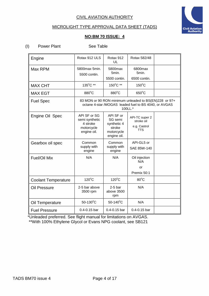
(I) Power Plant See Table
Engine Rotax 912 ULS Rotax 912 UL
Rotax 582/48
Max RPM 5800max 5min. 5500 contin.
5800max 5min.
5500 contin.
6800max 5min.
6500 contin.
MAX CHT 135oC ** 150oC ** 150oC
MAX EGT 880oC 880oC 650oC
Fuel Spec 83 MON or 90 RON minimum unleaded to BS(EN)228 or 97+ octane 4-star /MOGAS leaded fuel to BS 4040, or AVGAS
100LL.*
Engine Oil Spec API SF or SG semi synthetic
4 stroke motorcycle engine oil.
API SF or SG semi
synthetic 4 stroke
motorcycle engine oil.
API-TC super 2
stroke oil e.g. Castrol
TTS
Gearbox oil spec Common supply with
engine
Common supply with
engine
API-GL5 or SAE 85W-140
Fuel/Oil Mix N/A N/A Oil injection N/A or
Premix 50:1
Coolant Temperature 120oC 120oC 80oC
Oil Pressure 2-5 bar above 3500 rpm
2-5 bar above 3500
rpm
N/A
Oil Temperature 50-130oC 50-140oC N/A
Fuel Pressure 0.4-0.15 bar 0.4-0.15 bar 0.4-0.15 bar
*Unleaded preferred. See flight manual for limitations on AVGAS. **With 100% Ethylene Glycol or Evans NPG coolant, see SB121

CIVIL AVIATION AUTHORITY
MICROLIGHT TYPE APPROVAL DATA SHEET (TADS)
NO:BM 70 ISSUE: 4
TADS BM70 issue 4 Page 5 of 17
(8) INSTRUMENTS REQUIRED: 912 series engines
ASI
Altimeter RPM EGT Compass
CHT or Coolant
temp
Fuel Pressure
VSI Oil Temp
Oil Pressure
Slip ball
Required
(0-150mp
h.)
Required 0-20,000
ft
0-6000 Optional
50-150oC 375-
925oC
Optional
50-150oC 375-
925oC
Optional Optional 50-150 oC
0-8bar N/A 2 axis control
582 engine
ASI
Altimeter RPM EGT Compass Coolant temp
CHT Optional
Fuel Pressure
VSI
Required (0-
150mph.)
Required 0-20,000
ft
0-7000 0-800oC
Optional 80oC 0-300oC Optional Optional
(9) CONTROL DEFLECTIONS:
N/A weight shift control limits defined by structure geometry. Control bar move right = roll left Control bar push out = pitch up Trim switch up = slow trim Push left pedal = taxi steering right Push left toe = brakes on Push right toe = throttle open Hand throttle forward = throttle open Ignition switches up = switch on Choke forward = choke on Tap aligned with body = fuel on

CIVIL AVIATION AUTHORITY
MICROLIGHT TYPE APPROVAL DATA SHEET (TADS)
NO:BM 70 ISSUE: 4
TADS BM70 issue 4 Page 6 of 17
(10) PILOT'S NOTES, MAINTENANCE MANUALS REFERENCES:
10.1 Manuals approved for use with this aircraft. (a) GT 450 Operator’s manual, as amended. (b) Rotax 912 and 912-S Operator’s manual (c) Rotax 912 and 912-S Maintenance Manual. (d) Rotax 582 Operator’s manual. (e) Rotax 582 Maintenance Manual.
10.2 The following placards are to be fitted:- (a) Flight Limitations Placard (to be visible to pilot)
See Annex D.
(b) Engine Limitations Placard (to be located near to engine instruments) N/A limitations are programmed into electronic Rotax FLYDAT instrument or marked as red lines on the instrument faces
(c) Fuel Limitations Placard (to be located near to filler cap) See Annex D.
(d) Switches See Annex D.

CIVIL AVIATION AUTHORITY
MICROLIGHT TYPE APPROVAL DATA SHEET (TADS)
NO:BM 70 ISSUE: 4
TADS BM70 issue 4 Page 7 of 17
(11) MANDATORY MODIFICATIONS / SERVICE BULLETINS / AIRWORTHINESS DIRECTIVES ETC:
SB127 CKT Twin Exhausts
Check for cracking 08/09/09
SB132 Issue 4 Sail Reinforcement Test
Brooks testing 18/06/13
Annual Bettsometer test with a 1.2mm diameter needle, with wing sails fitted and tensioned enough to prevent puckering of sailcloth at the needle, is to be carried out to in accordance with Service Bulletin 133 issue 3. Applied loads: Upper & lower surface: 1360 grammes, for wings with Yellow Aramid Reinforcement. Or Upper & lower surface: 1000 grammes, for wings with Black Technora reinforcement. Loads to be applied spanwise and chordwise.
Stitches: 1360 grammes using a 1.2mm diameter hook, pull at 90degs to surface of tensioned sail.
Annual Brooksmeter test after first 2 years, using Brooksmeter, on untensioned wing trailing edge is to be carried out in accordance with Service Bulletin 132 issue 4. Applied loads: Aramid X-05 Yellow sail reinforcement: 9kgf or Technora Black sail reinforcement: 8kgf
(12) MINIMUM ISA PERFORMANCE AT MAX TAKE-OFF WEIGHT Rate of Climb: 1000 fpm at 55mph IAS (912 engine) 1200fpm at 55mph IAS (912-S engine) 550fpm at 55mph IAS (582/48 engine) Stall or Minimum Flying Speed: 38mph IAS at MTOW / idle.

CIVIL AVIATION AUTHORITY
MICROLIGHT TYPE APPROVAL DATA SHEET (TADS)
NO:BM 70 ISSUE: 4
TADS BM70 issue 4 Page 8 of 17
Issue History
Issue No. Reason and signatory 1 14/12/05 Initial Issue
A C LOVE 2 18/04/07 Update to include additional modifications
J C BARRATT 3 18/03/15 Betts & Brooks Test Limits Amended & General Update
A C LOVE 4 03/06/15 Introduction of Rotax 582 engine option, vented
undersurface wing with tip fins now optional.
A C LOVE

CIVIL AVIATION AUTHORITY
MICROLIGHT TYPE APPROVAL DATA SHEET (TADS)
NO:BM 70 ISSUE: 4
TADS BM70 issue 4 Page 9 of 17
Illustration of Aircraft - 3 View

CIVIL AVIATION AUTHORITY
MICROLIGHT TYPE APPROVAL DATA SHEET (TADS)
NO:BM 70 ISSUE: 4
TADS BM70 issue 4 Page 10 of 17
ANNEX A – MANDATORY MODIFICATIONS CAA Mandatory modifications: Nil P&M Aviation compulsory modifications: Nil

CIVIL AVIATION AUTHORITY
MICROLIGHT TYPE APPROVAL DATA SHEET (TADS)
NO:BM 70 ISSUE: 4
TADS BM70 issue 4 Page 11 of 17
ANNEX B - APPROVED OPTIONAL MODIFICATIONS The installation of all optional modifications is to be inspected by a BMAA inspector and an entry made in the appropriate logbook(s). Note that other approved modifications may exist which are not listed here.
Mod Ref Description Notes Issued
PG371 Instructor bars Optional 03/10/02
M135 BRS parachute Optional 04/02/05
M137 Low drag panniers Optional 06/04/05
M140 Keel nose holes bush Optional, std. repair 06/04/05
M141 Cross boom end hole bush
Optional, std. repair 06/04/05
M142 Leading edge front bush Optional, std. repair 06/04/05
M147 Quik Bush tube sleeve for basetube
Optional 12/05/05
M152 Cranked Brake Pedal Quik Hydraulic Brakes
Optional 28/07/05
M153 Landing light Optional 31/08/05
M156 Engine Cover & Large Radiator type ELR-003. Optional 12/02/06
M157 Standard GPS & Power socket
Optional 12/01/06
M160 New trim system pulley assy
Optional 19/01/06
M162
CKT exhaust and cooling pack QUIK and GT450, Rotax 912 and 912-S
Optional 15/11/06
M164 Move Cooling Pack Lower Rearwards
Optional 26/06/07
M165 Lower Pylon Face Bearing
Optional 28/06/07
M166 Mylar Cover On Sail Protection Patch
Optional 25/10/06
M168 New coolant overflow bottle mounted on gearbox
Optional 14/03/06

CIVIL AVIATION AUTHORITY
MICROLIGHT TYPE APPROVAL DATA SHEET (TADS)
NO:BM 70 ISSUE: 4
TADS BM70 issue 4 Page 12 of 17
Mod Ref Description Notes Issued
M176 Oil Hose Fastened to Gearbox
Optional 27/07/06
M180 Larger Instrument Panel Optional 19/03/07
M204 Webs on Subframe Optional 11/03/08
M217 Stoneguard Optional 10/01/11
M218 Enigma Instrument Optional 30/09/08
M220 PX10T Leading Edge Material
Optional 03/09/08
M224 Aveo LED Postion & Strobe Light
Optional 15/10/08
M225 Trim Pot Optional 20/02/09
M231 Radio/Transponder/ELT Optional 24/07/09
M232 Seat Belt Protection Sleeve
Optional 20/08/09
M234 Hand Controls Optional 12/02/10
M235 YTZ-14 Battery Optional 11/12/09
M236 Technoral Strips Optional 30/06/10
M238 GT450 Tug Optional 04/10/10
M242 Rear Axle Aerial Mnt Optional 31/01/11
M244 Oil & Coolant Thermostats
Optional 27/10/11
M249 Super B Battery Optional 09/11/11
M250 UV (TNF215 or CB) Sailcloth
Optional 27/05/11
M251 Screen Washer Optional 15/06/11
M256 Explorer Large Wheels and Brakes
Optional 21/03/12
M270 Sail TE Reinforcement Optional 07/12/12
M282 Fournales Shocks Optional 25/07/14
M286 Spinner Optional 12/12/14
M289 Rotax 582/48 engine Optional 15/03/15
M290 Vented undersurface Optional 15/03/15

CIVIL AVIATION AUTHORITY
MICROLIGHT TYPE APPROVAL DATA SHEET (TADS)
NO:BM 70 ISSUE: 4
TADS BM70 issue 4 Page 13 of 17
ANNEX C WEIGHING INFORMATION
The table below is a guide only. Empty weights include unusable fuel, full oil, electrolyte and prepared ready for flight.
ITEM WEIGHT kg
Quik -912 Trike 167 Quik – 582 Trike
GT 450 wing only 154 51.5
OPTIONAL ITEMS MAP BOX-FABRIC 0.76
50mm FRONT SEAT BOOSTER PAD 0.27 50mm FRONT S/BACK BOOSTER PAD ET 0.25
50mm REAR BOOSTER PAD 0.27 100mm REAR BOOSTER PAD 0.42
CONTROL BAR PROTECTION (2) 0.05 FRONT STRUT PROTECTION 0.04
LYNX ANTENNA 0.19 LYNX FILTER, POWER INT, PTT 0.81
INSTRUCTOR BARS 2.4 ICOM HAND HELD RADIO 0.3

CIVIL AVIATION AUTHORITY
MICROLIGHT TYPE APPROVAL DATA SHEET (TADS)
NO:BM 70 ISSUE: 4
TADS BM70 issue 4 Page 14 of 17
ANNEXE D
EXAMPLE PLACARDS
Title Location Flight Limitations: On LH wing upright Engine Limitations: On panel Aircraft Weights: On basetube Baggage Limitations: On baggage container Fuel Type, Capacity and Mix Ratio: On rear suspension leg Fuel Cock On/Off Positions: On seat Ignition Switch On/Off Positions: On ignition switch bracket Propeller Pitch Setting: On airbox or radiator Hand Throttle: On throttle unit Wiring Loom Disconnection Warning: On airbox or carb covers Trimmer Setting: On trim switch ( electric trim) On trim display (electric trim) Tip Turn Adjusters: On leading edge tube tips Latch Locking: On seat next to latch Oil Type and Quantity: On oil cap Propeller Pitch: On oil cooler Fuel Load Limitations: In the cockpit
TRIM INDICATOR AND TRIM SWITCH PLACARDS
TRIM
SLOW / UP
FAST / DOWN

CIVIL AVIATION AUTHORITY
MICROLIGHT TYPE APPROVAL DATA SHEET (TADS)
NO:BM 70 ISSUE: 4
TADS BM70 issue 4 Page 15 of 17
MAIN PLACARD (912 series engines)
P&M AVIATION
QUIK GT450
FLIGHT LIMITATIONS MANOEUVRING SPD 80MPH NEVER EXCEED Vne 110MPH MAX CROSS WIND 12MPH ENGINE LIMITATIONS MAX OIL PRESSURE 7 BAR MIN OIL PRESSURE 1.5 BAR MAX OIL TEMP (912) 140 DegC (912S) 130 DegC MIN OIL TEMP 50 DegC MAX CHT (912) 150 DegC (912S) 135 DegC MAX CONT RPM 5500 MAX RPM 5800 PAYLOAD LIMITATIONS MAX. TAKE OFF WEIGHT 450KG MAX. COCKPIT LOAD 220KG MAX. P1 LOAD 110KG MAX PASSENGER LOAD 110KG MIN P1 LOAD 55KG DO NOT EXCEED MAX. LOAD
www.pmaviation.co.uk
WARNING
MINIMUM FULL POWER CLIMB SPEED 40 MPH
DO NOT EXCEED 60 DEGREES ANGLE OF BANK
THIS AIRCRAFT IS NON-AEROBATIC NO WHIPSTALLS, WINGOVERS, TAILSLIDES, LOOPS, ROLLS OR
SPINS

CIVIL AVIATION AUTHORITY
MICROLIGHT TYPE APPROVAL DATA SHEET (TADS)
NO:BM 70 ISSUE: 4
TADS BM70 issue 4 Page 16 of 17
MAIN PLACARD (582 ENGINE)
P&M AVIATION
QUIK GT450 LITE 582
FLIGHT LIMITATIONS MANOEUVRING SPD 80MPH NEVER EXCEED Vne 110MPH MAX CROSS WIND 12MPH
ENGINE LIMITATIONS
MAX EGT 650oC MAX CHT 150oC MAX COOLANT 80oC MAX CONT RPM 6500 MAXRPM (5 min) 6800
PAYLOAD LIMITATIONS MAX. TAKE OFF WEIGHT 450KG MAX. COCKPIT LOAD 220KG MAX. P1 LOAD 110KG MAX PASSENGER LOAD 110KG MIN P1 LOAD 55KG MAX. TAKE OFF WEIGHT 450KG MAX. COCKPIT LOAD 220KG DO NOT EXCEED MAX. LOAD WARNING MINIMUM FULL POWER CLIMB SPEED 40 MPH DO NOT EXCEED 60 DEGREES ANGLE OF BANK THIS AIRCRAFT IS NON-AEROBATIC NO WHIPSTALLS, WINGOVERS, TAILSLIDES, LOOPS, ROLLS OR SPINS NO NEGATIVE G MAINTAIN POITIVE ‘G’ LOADING AT ALL TIMES FLY SOLO FROM FRONT SEAT ONLY
www.pmaviation.co.uk

CIVIL AVIATION AUTHORITY
MICROLIGHT TYPE APPROVAL DATA SHEET (TADS)
NO:BM 70 ISSUE: 4
TADS BM70 issue 4 Page 17 of 17
MISCELLANEOUS PLACARDS. IGNITION SWITCH PLACARD IS SPLIT AND USED FOR BOTH MAG SWITCHES.

��������������� ���������������������������������������� � !"�#$%"&�'�()%*+",�'--.��/�$))*,0$/)"�12%3�4,%2)5"�667897$9�*:�%3"�42,�;$<2=$%2*/�(,0",�'-->�$ �$?"/0"0�%3"�:*55*12/=�$)%2*/�,"@!2,"0�+A�%32 �B$/0$%*,A�C",?2%�#2,")%2<"�7BC#9�2 �?$/0$%*,A�:*,�$DD52)$+5"�$2,),$:%�,"=2 %","0�2/�%3"�E/2%"0�F2/=0*?�*D",$%2/=�*/�$�EF�G44�C",?2%�%*�H5AI��������������J���KL�MLN��C"=$ ! �GFO�"P3$! %�Q�RS�T��� 455�C"=$ ! �U!2V�W",2" �42,),$:%�X�U!2VY�U!2V�ZO[>-�$/0�U!2V�\�$2,),$:%�:2%%"0�12%3�GFO� %$2/5" � %""5�%12/�"P3$! % �132)3�3$<"� ",2$5�/!?+", �]'-�%*�][-I��__��T�R���������a���� 4/�!/ $:"�)*/02%2*/�3$ �+""/�20"/%2:2"0�13","�:$%2=!"�:$25!,"�*:�$/� 25"/)",�"/0�)$D�)*!50�," !5%�2/�%3"�+$::5"�%!+"�+"2/=�"b")%"0�:,*?�%3"� 25"/)",I��:�%32 �*))!,,"0�0!,2/=�:52=3%�%3"�%!+"�)*!50�"/%",�%3"�D,*D"55",�02 )�)$! 2/=�D,*D"55",�:$25!,"Y�%32 �)*!50�+"�3$c$,0*! I����_����T��� 6I��d":*,"�:!,%3",�:52=3%Y�:,*?�%3"�"::")%2<"�0$%"�*:�%32 �BC#Y�)$,,A�*!%�%3"�2/ D")%2*/�20"/%2:2"0�2/�4GO�(;e�/ D")%2*/�=2<"/�2/�CfB�4<2$%2*/�W",<2)"�d!55"%2/�/!?+",�6'g�2 !"�'�*,�5$%",�$DD,*<"0�,"<2 2*/I��'I��:�/*�),$)V �$,"�:*!/0�%3"�$2,),$:%�?$A�+"�,"%!,/"0�%*� ",<2)"�+!%�CfB�?*02:2)$%2*/�'']�?! %�+"�0*/"�+":*,"�%3"�$2,),$:%h �/"P%�D",?2%�,"/"1$5I��� G",%2:A�%3"�1*,V�)$,,2"0�*!%�$ � D")2:2"0�2/�%3"�#*)!?"/%$%2*/� ")%2*/�*:�CfB�4<2$%2*/�W",<2)"�d!55"%2/�/!?+",�6'g�2 !"�'�*,�5$%",�$DD,*<"0�,"<2 2*/I���I��:�),$)V �$,"�:*!/0Y�,"?*<"�$/0�2/%",/$55A�2/ D")%�%3"� 25"/)", �2/�$))*,0$/)"�12%3�4GO�(;e�\"?*<$5�=2<"/�2/�CfB�4<2$%2*/�W",<2)"�d!55"%2/�/!?+",�6'g�2 !"�'�*,�5$%",�$DD,*<"0�,"<2 2*/I��[I��:�$�,"D5$)"?"/%�*,�,"D$2,"0� 25"/)",�2 �%*�+"�,"X2/ %$55"0�2%�?! %�"2%3",&�� 7$9�i$<"�?*02:2)$%2*/�'']�$5,"$0A�2/ %$55"0Y�*,�� 7+9�d"�*:�$�5$%",�?*02:2)$%2*/� %$/0$,0�20"/%2:2"0�+A�%3"� 25"/)",�"/0�)$D Y�132)3�$,"����������������� ?**%3�12%3�/*�+$::5"�%!+"�)*//")%2*/Y�"P3$! %� ",2$5�/!?+",�6-.[-]-.�*/1$,0 I�� G",%2:A�%3"�1*,V�)$,,2"0�*!%�$ � D")2:2"0�2/�%3"�#*)!?"/%$%2*/� ")%2*/�*:�CfB�4<2$%2*/�W",<2)"�d!55"%2/�/!?+",�6'g�2 !"�'�*,�5$%",�$DD,*<"0�,"<2 2*/I��������� !"�'�*:�%3"�W",<2)"�d!55"%2/� !D", "0" �%3"�D,"<2*! 5A�2 !"0�<", 2*/I�j�a����T��_����T��k�������a������a���T����������������T��l�����R��mn�jll�T����������� 8�()%*+",�'--.�6I�O32 �BC#�1$ �/*%�D!+52 3"0�:*,�)*/ !5%$%2*/�+")$! "�*:�%3"�!,="/)A�*:�%3"�,"@!2,"?"/%I�'I�o/@!2,2" �,"=$,02/=�%32 �BC#� 3*!50�+"�,":",,"0�%*�42,),$:%�G",%2:2)$%2*/�#"D$,%?"/%Y�G2<25�4<2$%2*/�4!%3*,2%AY��W$:"%A�\"=!5$%2*/�Z,*!DY�4<2$%2*/�i*! "Y�Z$%12)V�42,D*,%�W*!%3Y�p" %�W! "PY�\i8�-q\Y�E/2%"0�F2/=0*?I����O"5&�r[[�7-96'.�>g'-g���H$P&�r[[�7-96'.�>g.g8��o?$25&�0"D$,%?"/%I)",%2:2)$%2*/s)$$I)*I!V���

������������ �� ���� ������������ �������
����������� !�"�# $��%&�'(�)*+,-.+&/)(/+.�)/0.'"123$456778669+7:;;<�����=��><������ /!�?? $@�!?3A��#55B7C D��$'���E��� !*$@3$566F�G�13!@3@�#3D �� A�!E�?�� !$3H"�$3@2%�#�G&�!@�� $%-3$1��(�$3?���3B&-(C�G1�!@�� $%D $�II��?�2�3��$?$�D�$3E�G�3$3@�!�#3J!��3@K�!E@ 1 I3$���!E !�JK���-3$1��� L�%MN�O�POO����QR�Q���S;T���=-U&������ ! N�O�V����Q��; ���� ��W;X=-3E�G"GY"�Z[Y"�Z\)]96[Y"�Z+)���34 ���$3�!D $?313!�@3E$�@��� !_�@@��� !���3G�&�!"D�?�"$3$4 �P� �� ��a��b�II��?�2����%4 ���;<;c< dec< dfNg��ec< d�h �ij�����N��i������� ����������k���;b+3�G !4 P� �� ����h �i�g����V����i�<�;�Q �i�� ��hi ��������;� Q�� �k���i�;;i�h��i���i�;�������l���;��������;�<;����O��� ���������� ��������k�<;��bNi ;�� ;<O���������� ; ������Q�� ���i���i�� �������<;����k��Q�h� ��i�k���;�� Q�i���;�b.DD3?���3(��34 ��><������Ni ; ;�i�;��������� �������;�i��� � ��Q��b� 1I���!?3m�?�� !4 n��� �����������i�������;�Q��������i�����i�<�;�Q �i�� ��ehi �i��������;� �;�eO�������i���;��;��;�� k�� � �P� �� ��a��o��� ��l<QQ�� �T<�k���p�h �i ��i���q���i�<�;�����i������� ���������i ;��e�<� ��hi �iO�� ��i �if�����<���;�<;�k���� ���bn���QQ� ������O�������i���;��;��;�� k�� � �P� �� ��a��o��� ��l<QQ�� �T<�k���p������i���<�Q �;O��� ��:��i���������i��� ����������k���;�� Q ���i���;���;�� k�� �ol�p�������� �P� �� ��a � �������i�� �������<;����k��Q�h�<�� Q;�� ;���������;�Q<� �� ;���� ������� �P� �� ��a � ���bT���=�XP��O���o��� ��l<QQ�� �T<�k���p����k��k�� �������=�P� �� ��r� �ls��h����o��������i��Q�a����;i ��ta�u�TrN�Q=��v�uu���pgw�� Q=�Q� ��xO��� �� ��b��b<d

����������������� ��������� ���� ������ ������������������������������������������������������������������������������������� � �����������������
������ ���� ������ ������������������� �� ����!���
"#$%&"�'()*+,-#'"�.,/0�/0,$�)*1�,$�&"'(&1"1�,#�/0"�-,&'&-2/�+(34((5�&676869:6�*;<=>:?@>A9BC� ��D����������E����� �����F�������G��H� ��I��&6J?8KBC� L�MN�O��� � ����������!��������������������P�Q�������N��L�MN�RS�� ���� � � �� ����������������H�� �!� ����T��� � �������R������������� �����������U� ����V������������������ ���V���!������ ������� �UV��������W���V�������X��� U ������V�Y���������Z��W[��\�N�O��T�] �_���PI��aII�I� b�ZT�] �_���PI��aIPa[�R�����T���U� ����N�� ��!�����c���N�N�X���

Mandatory Permit Directive 2012-005-E Page 1 of 2
Civil Aviation Authority EMERGENCY MANDATORY PERMIT DIRECTIVE Number: 2012-005-E Issue date: 21 November 2012
In accordance with 22(1) of Air Navigation Order 2009 as amended the following action required by this Mandatory Permit Directive (MPD) is mandatory for applicable aircraft registered in the United Kingdom operating on a UK CAA Permit to Fly.
Type Approval Holder’s Name: P&M Aviation
Type/Model Designation(s): Pegasus Quik, Quik GT 450, QuikR and Quik GTR
Title: Sail Reinforcement Degradation – Additional Test
Manufacturer: P&M Aviation Ltd.
Applicability: Pegasus Quik, Quik GT450, QuikR and Quik GTR with X-05 or Technora reinforcement bands.
Reason: An incident in 2011 with a 4 year/1500 Hours flight time sail showed that the standard Bettsometer test used to predict sail strength degradation could not be used. This issue was addressed by the application of MPD No. 2011-005 Revision 1. A subsequent incident in September 2012, with a 6 year/1000 Hours flight time sail, has necessitated a revision to the previously defined test limits and compliance periods. Additionally, the applicability has been revised to incorporate the Quik GTR, which was not in production at the time of the original MPD. As such, P&M Aviation has revised Service Bulletin (SB) 132 to Issue 2 in order to reflect the revised criteria. This MPD 2012-005 supersedes MPD No. 2011-005 R1.
Effective Date: 21 November 2012
Civil Aviation Authority Mandatory Permit Directive SRG Airworthiness Division
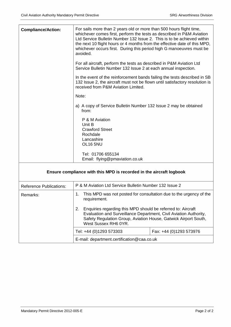
Mandatory Permit Directive 2012-005-E Page 2 of 2
Compliance/Action: For sails more than 2 years old or more than 500 hours flight time, whichever comes first, perform the tests as described in P&M Aviation Ltd Service Bulletin Number 132 Issue 2. This is to be achieved within the next 10 flight hours or 4 months from the effective date of this MPD, whichever occurs first. During this period high G manoeuvres must be avoided. For all aircraft, perform the tests as described in P&M Aviation Ltd Service Bulletin Number 132 Issue 2 at each annual inspection. In the event of the reinforcement bands failing the tests described in SB 132 Issue 2, the aircraft must not be flown until satisfactory resolution is received from P&M Aviation Limited. Note: a) A copy of Service Bulletin Number 132 Issue 2 may be obtained
from:
P & M Aviation Unit B Crawford Street Rochdale Lancashire OL16 5NU Tel: 01706 655134 Email: [email protected]
Ensure compliance with this MPD is recorded in the aircraft logbook
Reference Publications: P & M Aviation Ltd Service Bulletin Number 132 Issue 2
Remarks: 1. This MPD was not posted for consultation due to the urgency of the requirement.
2. Enquiries regarding this MPD should be referred to: Aircraft
Evaluation and Surveillance Department, Civil Aviation Authority, Safety Regulation Group, Aviation House, Gatwick Airport South, West Sussex RH6 0YR.
Tel: +44 (0)1293 573303 Fax: +44 (0)1293 573976
E-mail: [email protected]

Mandatory Permit Directive 2016-008-E Page 1 of 2
Civil Aviation Authority
EMERGENCY MANDATORY PERMIT DIRECTIVE Number: 2016-008-E Issue date: 3 October 2016
In accordance with Article 41(1) of The Air Navigation Order 2016, as amended, the following action required by this Mandatory Permit Directive (MPD) is mandatory for applicable aircraft registered in the United Kingdom operating on a UK CAA Permit to Fly.
Type Approval Holder’s Name: P&M Aviation Ltd
Type/Model Designation(s): Pegasus XL-Q variants, Pegasus Quasar variants, Pegasus Quantum variants, Pegasus Quik, Quik, Quik GT450, Quik Lite, Gemini Flash IIA, Mainair Blade variants
Title: Wing – Luff Line Attachment Webbing – Inspection
Manufacturer: P&M Aviation Ltd
Applicability: Pegasus XL-Q variants, Pegasus Quasar variants, Pegasus Quantum variants, Pegasus Quik, Quik, Quik GT450, Quik Lite, Gemini Flash IIA, Mainair Blade variants.
Reason: The port inner luff line attachment webbing failed on a GT450 wing with 620 hours airtime during taxiing.
The polyester webbing loop had chafed against the chrome plated brass eyelet. The webbing wear was visible from the top side, but not from the underside of the sail.
A detached luff line is hazardous as it may go into the propeller. Pitch stability in a steep dive or in turbulence would also be compromised.
It appears that the eyeleting process has been forming a ridge inside it capable of damaging the webbing. New tooling has been introduced at the Factory to prevent recurrence of the problem.
Effective Date: 3 October 2016
Compliance/Action: Compliance is required as follows, unless previously accomplished:
1. Before further flight, inspect the luff line attachment webbings in accordance with paragraph 2.1 of P & M Aviation Ltd Service Bulletin 142. If there is no sign of damage to the webbing, the aircraft may continue in service.
2. Before further flight, inspect the luff line attachment webbings in accordance with paragraph 2.1 of P & M Aviation Ltd Service Bulletin 142. If there is no sign of damage to the webbing, the aircraft may continue in service.
Civil Aviation Authority Mandatory Permit Directive SARG Airworthiness
Mandatory Permit Directive 2016-008-E Page 2 of 2
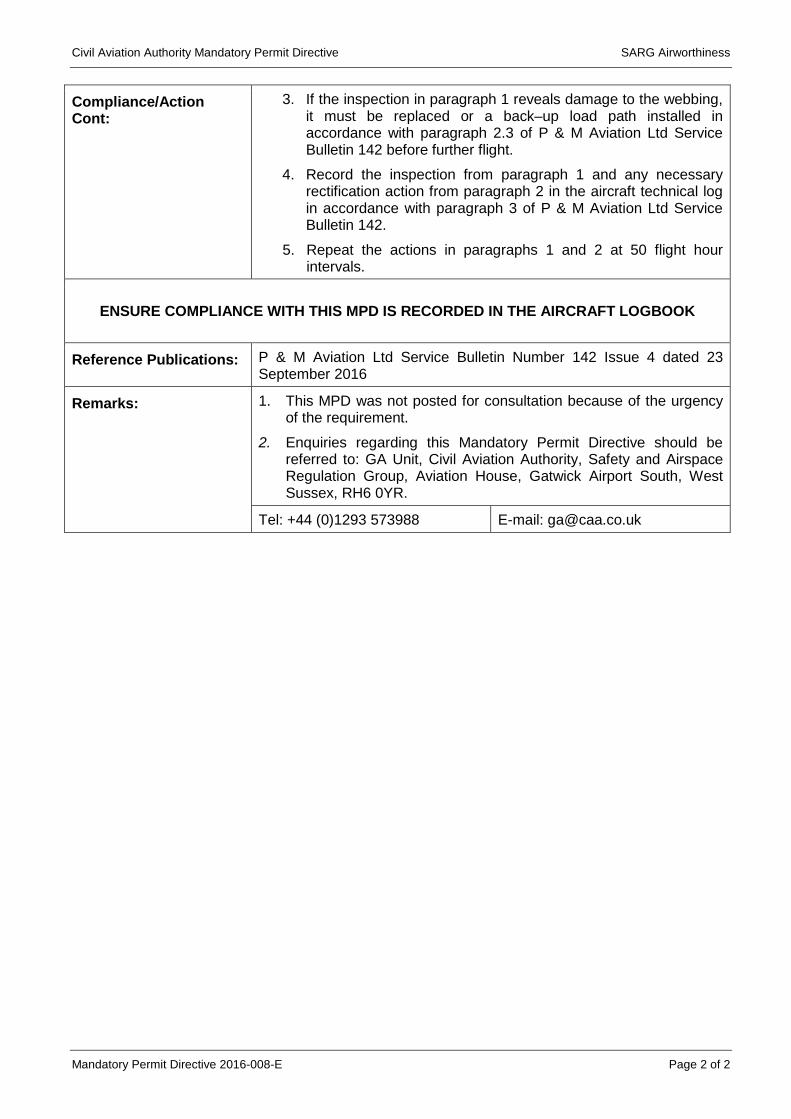
Compliance/Action Cont:
3. If the inspection in paragraph 1 reveals damage to the webbing, it must be replaced or a back–up load path installed in accordance with paragraph 2.3 of P & M Aviation Ltd Service Bulletin 142 before further flight.
4. Record the inspection from paragraph 1 and any necessary rectification action from paragraph 2 in the aircraft technical log in accordance with paragraph 3 of P & M Aviation Ltd Service Bulletin 142.
5. Repeat the actions in paragraphs 1 and 2 at 50 flight hour intervals.
ENSURE COMPLIANCE WITH THIS MPD IS RECORDED IN THE AIRCRAFT LOGBOOK
Reference Publications: P & M Aviation Ltd Service Bulletin Number 142 Issue 4 dated 23 September 2016
Remarks: 1. This MPD was not posted for consultation because of the urgency of the requirement.
2. Enquiries regarding this Mandatory Permit Directive should be referred to: GA Unit, Civil Aviation Authority, Safety and Airspace Regulation Group, Aviation House, Gatwick Airport South, West Sussex, RH6 0YR.
Tel: +44 (0)1293 573988 E-mail: [email protected]

Mandatory Permit Directive 2016-011 Page 1 of 2
Civil Aviation Authority
EMERGENCY MANDATORY PERMIT DIRECTIVE Number: 2016-011-E Issue date: 23 November 2016
In accordance with Article 41(1) of The Air Navigation Order 2016, as amended, the following action required by this Mandatory Permit Directive (MPD) is mandatory for applicable aircraft registered in the United Kingdom operating on a UK CAA Permit to Fly.
Type Approval Holder’s Name: P&M Aviation Ltd
Type/Model Designation(s): Various, see below
Title: Clevis Pin / Split Ring Installations – Inspection / Replacement
Manufacturer: P&M Aviation Ltd
Applicability: All Microlights where P & M Aviation Ltd is the Type Approval Holder: TADS No. Aircraft Type TADS No. Aircraft Type BM2 Gemini Sprint BM43 Mainair Mercury BM3 Tri-Flyer Sprint BM44 Pegasus Quasar 2 TC BM4 Gemini Flash BM45 Cyclone AX3//503 BM5
Panther XL-S BM46 Pegasus Quantum 15 (Rotax 2-stroke engines)
BM9 Pegasus XL-R BM47 Mainair Blade BM10 Pegasus Flash BM50 Pegasus Quantum 15-912 BM17 Pegasus Flash 2 BM51 Mainair Blade 912 BM14 Gemini Flash 2 BM53 Cyclone AX2000 BM16 Scorcher BM54 Mainair Rapier BM17 Pegasus Flash 2 BM56 Pegasus Quantum 15-HKS BM23 Gemini Flash 2 Alpha BM60 Mainair Blade 912S BM25 Pegasus XL-Q
BM65 Flight Design CT2K
(rudder control) BM27 Chaser S BM66 Pegasus Quik BM28 Pegasus Photon BM70 Quik GT450 BM31 Chaser S 1000
BM72 Flight Design CTSW
(rudder control) BM33 Chaser S 508 BM77 QuikR BM37 Chaser S 447 BM80 Quik GTR BM38 Pegasus Quasar BM81 PulsR BM42 Pegasus Quasar – TC
BM83 Flight Design CTSL
(rudder control)

Civil Aviation Authority Mandatory Permit Directive SARG
Mandatory Permit Directive 2016-011 Page 2 of 2
Reason: Following maintenance, a clevis pin came out of the RP-4 roll trim system pulley on a QuikR causing a left turn. The split ring securing the clevis pin had come out. It is not known if the ring was disturbed during the maintenance. The split ring which came out was the same “spiral start” pattern as that which has caused trouble before (see Service Bulletin 139). This pattern of ring has no positive stop, so that simple rotation of the ring (e.g. caused by it getting caught on something) will cause it to disengage. Disengagement of the split ring and subsequent clevis pin departure could affect the control of the aircraft.
Effective Date: 24 November 2016
Compliance/Action: Compliance is required as follows, unless previously accomplished:
1. Before further flight, from the effective date of this MPD, inspect all clevis pin / split ring installations on the aircraft in accordance with paragraph 2 of P & M Aviation Ltd Service Bulletin 144.
2. If the inspection in paragraph 1 reveals any spiral start pattern split rings they must be replaced in accordance with paragraph 2 of P & M Aviation Ltd Service Bulletin 144 before further flight.
3. Record the inspection from paragraph 1 and any necessary rectification action from paragraph 2 in the aircraft technical log in accordance with paragraph 3 of P & M Aviation Ltd Service Bulletin 144.
4. Repeat the actions in paragraphs 1, 2 and 3 at each Permit to Fly revalidation.
ENSURE COMPLIANCE WITH THIS MPD IS RECORDED IN THE AIRCRAFT LOGBOOK
Reference Publications:
P & M Aviation Ltd Service Bulletin Number 144, Issue 3, dated 27 October 2016.
Remarks: 1. This MPD was not posted for consultation because of the urgency of the requirement.
2. Enquiries regarding this Mandatory Permit Directive should be referred
to: GA Unit, Civil Aviation Authority, Safety and Airspace Regulation Group, Aviation House, Gatwick Airport South, West Sussex, RH6 0YR.
Tel: +44 (0)1293 573988 E-mail: [email protected]

Mandatory Permit Directive 2017-003-E Page 1 of 2
Civil Aviation Authority
EMERGENCY MANDATORY PERMIT DIRECTIVE Number: 2017-003-E Issue date: 21 February 2017
In accordance with Article 41(1) of The Air Navigation Order 2016, as amended, the following action required by this Mandatory Permit Directive (MPD) is mandatory for applicable aircraft registered in the United Kingdom operating on a UK CAA Permit to Fly.
Type Approval Holder’s Name:
P&M Aviation Ltd Type/Model Designation(s):
Various, see below
Title: Hang Bolt plus Lanyard – Inspection / Replacement
Manufacturer: P&M Aviation Ltd
Applicability: All Microlights of the following types where P & M Aviation Ltd are the Type Approval Holder: TADS No. Aircraft Type BM44 Pegasus Quasar 2 TC BM46 Pegasus Quantum 15
(Rotax 2-stroke engines) BM50 Pegasus Quantum 15-912 BM56 Pegasus Quantum 15-HKS BM66 Pegasus Quik BM70 Quik GT450 BM77 QuikR BM80 Quik GTR BM81 PulsR
Reason: The lanyard on a hang bolt plus lanyard component was found to be under swaged which allowed it to detach at a low load. The lanyard is essential to stop the hang bolt pinch nut from slackening off. Should the pinch nut fall off there would not be anything to prevent the hang bolt from potentially migrating out of its housing and the wing would then detach. This problem was identified as a manufacturing deficiency of part number YQB-31302 and affected three batches of the component: A9835, A9868 and A9880.
Effective Date: 21 February 2017

Civil Aviation Authority Mandatory Permit Directive Safety and Airspace Regulation Group
Mandatory Permit Directive 2017-003-E Page 2 of 2
Compliance/Action: Compliance is required as follows, unless previously accomplished:
1. Before further flight, inspect the hang bolt plus lanyard, part number YQB-31302. If the lanyard is from batch number A9835, A9868 or A9880, before further flight, remove the hang bolt plus lanyard from the aircraft and return to P & M Aviation Ltd for replacement. Note: The hang bolt plus lanyard part number and batch number are marked on the sleeve shrunk on to the lanyard.
2. Record the inspection from paragraph 1 and any necessary
rectification action in the aircraft technical log in accordance with paragraph 3 of P & M Aviation Ltd Service Bulletin 146.
3. Repeat the actions in paragraphs 1 and 2 at each Permit to Fly
revalidation.
ENSURE COMPLIANCE WITH THIS MPD IS RECORDED IN THE AIRCRAFT LOGBOOK
Reference Publications:
P & M Aviation Ltd Service Bulletin Number 146 Issue 1 dated 6 January 2017
Remarks: 1. This MPD was not posted for consultation because of the urgency of the requirement.
2. Enquiries regarding this Mandatory Permit Directive should be referred
to: GA Unit, Civil Aviation Authority, Safety and Airspace Regulation Group, Aviation House, Gatwick Airport South, West Sussex, RH6 0YR.
Tel: +44 (0)1293 573988 E-mail: [email protected]
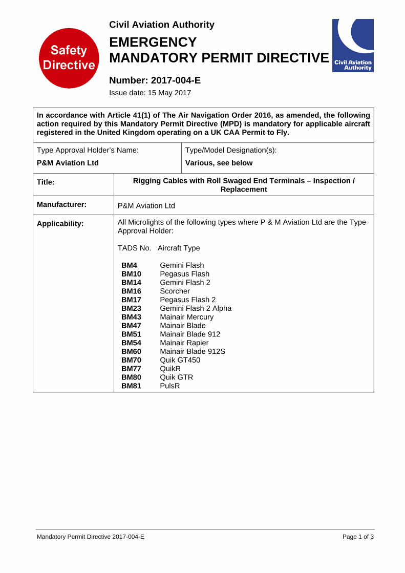
Mandatory Permit Directive 2017-004-E Page 1 of 3
Civil Aviation Authority
EMERGENCY MANDATORY PERMIT DIRECTIVE Number: 2017-004-E Issue date: 15 May 2017
In accordance with Article 41(1) of The Air Navigation Order 2016, as amended, the following action required by this Mandatory Permit Directive (MPD) is mandatory for applicable aircraft registered in the United Kingdom operating on a UK CAA Permit to Fly.
Type Approval Holder’s Name:
P&M Aviation Ltd Type/Model Designation(s):
Various, see below
Title: Rigging Cables with Roll Swaged End Terminals – Inspection / Replacement
Manufacturer: P&M Aviation Ltd
Applicability: All Microlights of the following types where P & M Aviation Ltd are the Type Approval Holder: TADS No. Aircraft Type BM4 BM10 BM14 BM16 BM17 BM23 BM43
Gemini Flash Pegasus Flash Gemini Flash 2 Scorcher Pegasus Flash 2 Gemini Flash 2 Alpha Mainair Mercury
BM47 Mainair Blade BM51 Mainair Blade 912 BM54 Mainair Rapier BM60 Mainair Blade 912S BM70 Quik GT450 BM77 QuikR BM80 Quik GTR BM81 PulsR

Civil Aviation Authority Mandatory Permit Directive Safety and Airspace Regulation Group
Mandatory Permit Directive 2017-004-E Page 2 of 3
Reason: A P&M Quik GT450 in a flying school had a partial failure of a lower side rigging cable (Part No. YQD-045) when recovering from a spiral manoeuvre, within the limits of the flight envelope. These cables are arranged in pairs, to give a backup load path. The second cable carried the load and the aircraft landed safely. This is the only recorded lower side cable failure since 1984. The partial failure was at the edge of the roll swaged terminal end. The alternative cable terminations using Nicopress sleeves and thimbles allow more progressive flexing of the cable. The incident Quik GT450 lower side rigging cables had been in use for 1050 hours and 9 years. The aircraft had been subject to an accident and rebuilt once in its life. It was also operated quite near the coast where it is probable that sea air chlorides could have affected the material. There were corrosion pits in the S316 stainless steel material which accelerate fatigue failures. CLSCC (Chloride Stress Corrosion Cracking) is known to affect stainless steel. The cable fitting was at the bottom end of the cable, where solutions can wick down it and collect. The strand failures were caused by bending and tensile fatigue because of cracks propagating from scratches and corrosion pits on the surface. All the remaining cables had broken strands at the edge of the roll swaged terminals. Some of these strands had been failed for some time, as shown by discolouration of the failure surfaces. The cable is 7 cores of 7 strands construction. Failure of a lower rigging cable would potentially reduce the integrity of the wing and hazard the aircraft.
Effective Date: 15 May 2017

Civil Aviation Authority Mandatory Permit Directive Safety and Airspace Regulation Group
Mandatory Permit Directive 2017-004-E Page 3 of 3
Compliance/Action: Compliance is required as follows, unless previously accomplished:
1. Before further flight, for lower side, front and rear rigging cables with roll swaged terminal ends with more than 750 flying hours or 7 years of service, whichever comes first, visually inspect at the edge of the roll-swaged terminal(s) using a magnifying glass with a power of at least 3x. Inspect closely for damage i.e. broken strands, corrosion, mechanical damage or slippage. If any damage is found, replace the affected cable before further flight. If no damage is found, replace the cable within 25 flying hours. See paragraphs 1 and 2 of P & M Aviation Ltd Service Bulletin 147 including the warning in paragraph 2.
2. Within 25 flying hours, for lower side, front and rear rigging cables
with roll swaged terminal ends with less than 750 flying hours and less than 7 years of service, visually inspect at the edge of the roll-swaged terminal(s) using a magnifying glass with a power of at least 3x. Inspect closely for damage i.e. broken strands, corrosion, mechanical damage or slippage. If any damage is found, replace the affected cable before further flight. If no damage is found, replace the cable at 750 flying hours or 7 years of service, whichever comes first. See paragraphs 1 and 2 of P & M Aviation Ltd Service Bulletin 147 including the warning in paragraph 2.
3. Removal and replacement of any airframe structural cable requires a duplicate inspection - see paragraph 3 of P & M Aviation Ltd Service Bulletin 147.
4. Record the inspection from paragraph 1 or paragraph 2 and any necessary rectification action in the aircraft technical log in accordance with paragraph 3 of P & M Aviation Ltd Service Bulletin 147.
5. Repeat the inspection in paragraph 2 at each Permit to Fly
revalidation and replace damaged cables as necessary. Replace the cables at 750 flying hours or 7 years of service, whichever comes first.
ENSURE COMPLIANCE WITH THIS MPD IS RECORDED IN THE AIRCRAFT LOGBOOK
Reference Publications:
P & M Aviation Ltd Service Bulletin Number 147 Issue 1 dated 10 May 2017
Remarks: 1. This MPD was not posted for consultation because of the urgency of the requirement.
2. Enquiries regarding this Mandatory Permit Directive should be referred
to: GA Unit, Civil Aviation Authority, Safety and Airspace Regulation Group, Aviation House, Gatwick Airport South, West Sussex, RH6 0YR.
Tel: +44 (0)1293 573988 E-mail: [email protected]