nixie-transistor clock assembly manual · kabtronics soldering nixie transistor clock kit ... 12...
TRANSCRIPT

Nixie-Transistor Clock Assembly Manual

K A B T R O N I C S I N T R O D U C T I O N
Nixie Transistor Clock Kit Page 2
Manual Version Date PCB version Change Details 1.2 6/6/2011 Version 3 Initial shipments 1.3 1/10/2012 Version 4 Updates from first builders 1.4 7/4/2013 Version 5 PS drive circuit mod, 24 Hour shutoff mod,
update schematic and BOM 1.5 6/29/2014 Version 5 Add text for oscillator frequency selection 1.6 4/2/2015 Version 5 Update BOM 1.7 10/8/2016 Version 5 Add SENSE resistor selection text
Document 1.7 for PCB version 5 Copyright © October 8, 2016 by KABtronics

K A B T R O N I C S I N T R O D U C T I O N
Nixie Transistor Clock Kit Page 3
Table of Contents
INTRODUCTION ........................................................................................................................................ 5
UNPACKING/PARTS LIST .......................................................................................................................... 6
SOLDERING .............................................................................................................................................. 7
UNSOLDERING ................................................................................................................................................. 8
OPTIONAL CLEAN-UP ........................................................................................................................................ 8
BUILD ORDER ........................................................................................................................................... 9
12 VOLT SUPPLY ............................................................................................................................................ 13
SECONDS COUNTER, DECODE, DRIVE ................................................................................................................. 22
THE REST OF THE COUNTERS ............................................................................................................................. 24
HOURS DECODE AND DRIVE ............................................................................................................................. 26
HIGH VOLTAGE POWER SUPPLY ........................................................................................................................ 29
HIGH VOLTAGE SWITCHER ............................................................................................................................... 30
NIXIE AND NEON DISPLAYS .............................................................................................................................. 34
FINAL ASSEMBLY AND TEST .............................................................................................................................. 36
PARTS IDENTIFICATION .......................................................................................................................... 38
RESISTORS .................................................................................................................................................... 38
CERAMIC CAPACITORS ..................................................................................................................................... 38
INDUCTORS ................................................................................................................................................... 39
DIODES ........................................................................................................................................................ 39
TRANSISTORS................................................................................................................................................. 40
TRANSISTORS – TO-220 POWER ....................................................................................................................... 40
LEDS ........................................................................................................................................................... 40
NEON BULB .................................................................................................................................................. 41
NIXIE TUBES AND SOCKETS ............................................................................................................................... 41
THEORY OF OPERATION ......................................................................................................................... 42
LOW LEVEL LOGIC ........................................................................................................................................... 43
COUNTER ..................................................................................................................................................... 44
CIRCUIT DESCRIPTION ............................................................................................................................ 47
IN CASE OF DIFFICULTY .......................................................................................................................... 54
GENERAL TROUBLESHOOTING ........................................................................................................................... 54
POWER SUPPLY DEBUGGING ............................................................................................................................ 55
DEBUGGING FLIP-FLOPS .................................................................................................................................. 56
DEBUGGING DECODERS ................................................................................................................................... 58
SPECIFICATIONS ..................................................................................................................................... 59
CIRCUIT BOARD VIEWS .......................................................................................................................... 60
SCHEMATIC ............................................................................................................................................ 63
COMPONENT SILK SCREEN SYMBOL ....................................................................................................... 86
K A B T R O N I C S I N T R O D U C T I O N
Nixie Transistor Clock Kit Page 4

K A B T R O N I C S I N T R O D U C T I O N
Nixie Transistor Clock Kit Page 5
Introduction
Thanks for buying this kit. After about 20 hours of assembly, and with a clock to show for your efforts, I hope you will thank me for offering this kit.
This is a complex kit meant for experienced electronic hobbyists. The High Voltage supply in this kit will produce over 160 Volts storing about 2 Joules of energy in the circuit. Touching the wrong thing, placing yourself in the electrical circuit will be very painful, and could possible kill you. You must keep your wits about you and maintain common sense protocols while working on this kit. I just have to make this obvious, so bear with me.
This kit can KILL you if you come in contact with the 160 Volts.
Here is the high voltage protocol – it applies after you build the High Voltage supply.
• Build the HV supply last, after the rest of the circuit is done, tested, and working.
• The 180 Volts will still be present even after removing power.
o You must wait for the 180 Volts to bleed off after removing power. You can use a volt meter to check for a safe voltage.
• If you are working on the board with the power applied, use the one-hand protocol
o Use only one hand to move test leads and whatever else you are doing to the board, the other hand is in your pocket, this is to prevent you completing a circuit with your body. The worst you could do is short out one hand, very painfully I will add.
Since you are an experienced kit builder the soldering section may be superfluous, you be the judge, but keep in mind;
You need to make 2917 good solder joints to have the clock work.
Also, a bad solder joint in the High Voltage supply can destroy components, perhaps in a spectacular fashion, if the voltage regulator isn’t working properly.

K A B T R O N I C S U N P A C K I N G / P A R T S L I S T
Nixie Transistor Clock Kit Page 6
Unpacking/Parts List
Present Qty Item
X 1 Assembly Manual
1 Resistor, 0.47ohm
1 Resistor, 10 ohm
1 Resistor, 100 ohm
75 Resistor, 1K ohm
180 Resistor, 10K ohm
180 Resistor, 100K
3 Resistor, 1Mohm
2 Resistor, 22 ohm
50 Resistor, 22K ohm
5 Resistor, 220Kohm
1 set Resistors, 348K, 357K, 390Kohm
1 Resistor, 47K ohm
1 Capacitor, 120uF
2 Capacitor, 6,800uF
1 Capacitor, 10uF,16V Tantalum
2 Capacitor, 0.001uF Ceramic
3 Capacitor, 0.01uF, Ceramic
13 Capacitor, 0.1uF, Ceramic
90 Capacitor, 220pF, Ceramic
2 Capacitor, 470, Ceramic
1 Inductor, 220uH, Toroid
1 Transformer, wall, 12VAC
150 Transistor, NPN, 2N3904
30 Transistor, PNP, 2N3906
1 Transistor, NPN Power, TO-220
50 Transistor, STX13003G,400V 1A
1 Transistor, PNP, MPSA56
16 LED, red 3mm
500 Diode, Signal, 1N4148
4 Diode,1N5818
1 Diode,3A, 400V
2 Zener, 4.7V, 0.5W
5 Neon Lamp
6 IN12A Nixie Display
1 Heatsink, Dual TO-220
13 Nut, 4-40
13 Screw, 4-40, 0.5in
13 Hardware, washer, 4-40
10 Nylon Tie Wraps
1 TermBlock, 2 Pos
6 Socket, Nixie, IN12A
3 Switch,
1 Fuse, 3A, Fast, pico
1 PCB, Nixie Version 3
22 feet Hookup wire
6 feet 2 conductor cable for power cord

K A B T R O N I C S S O L D E R I N G
Nixie Transistor Clock Kit Page 7
Soldering
This manual can’t teach the art of soldering, but here are the basics. Remember, you need to make about 2917 GOOD solder joints; each bad joint will be an adventure in troubleshooting.
Wet the tip of the iron with a bit of solder and wipe off the excess solder on the wet sponge occasionally, or when you notice the joint is not heating properly. The small amount of solder left on the tip helps conduct heat to the lead and the pad.
Insert the component leads and press the component flat against the PC Board. Slightly spread the leads to hold it in place when you flip the board over to expose the back side with the component lead facing up.
• Make good contact between the iron, the lead, and the pad on the board so the lead and the pad both heat up enough to melt the solder.
• It should take from 0.5 to 1 second for the joint to become hot enough to melt the solder.
• Don’t overheat the joint, as soon as the solder melts and wicks into the joint remove the iron and hold still for a few seconds until the joint freezes.
• Be careful not to press too hard while soldering; the trace can break at the copper ring and that broken trace will be hard to find.

K A B T R O N I C S S O L D E R I N G
Nixie Transistor Clock Kit Page 8
A good solder joint will form a shiny curved surface bonding the lead and the pad on the PC board. If the lead wasn’t heated enough to melt the solder, the solder will wick in to the pad, but will not adhere to the lead. You may notice a dark line around the lead where the solder dives down through the hole.
A similar bad joint forms when the pad wasn’t heated enough to melt the solder. A cold solder joint can often be fixed by reheating the joint; sometime a little more solder will be needed.
More detailed instructions can be found on the internet with a little searching on the topic of soldering.
After inspecting the solder joint, clip off the excess lead using the diagonal cutter. Cut at the top of the solder joint; don’t dig into the solder joint.
Unsoldering
A supply of de-soldering braid is supplied with the kit. If you find the need to remove a component, use the de-solder braid by pulling out a few inches and pressing the braid against the lead and the pad using the iron. You will see the solder melt and spread into the wick leaving very little solder left in the pad.
Sometimes it helps to clip the lead off the component so you can deal with each lead separately.
Optional Clean-up
The clear sticky rosin left around the solder site can be cleaned up with alcohol (not “rubbing alcohol”) and a toothbrush, but be sure to let the board dry before expecting the board to operate properly. You won’t hurt the circuit by powering it up, but it won’t count right until the board has completely dried. As for me, I don’t bother to clean up the board unless the counters are not working right, then I do clean off the rosin.
If you do clean the board, be sure to really clean it, not just redeposit the gunk over the board in an even layer; that will cause unreliable operation as these counters are very sensitive to leakage currents that will pass through the gunk layer.

K A B T R O N I C S B U I L D O R D E R
Nixie Transistor Clock Kit Page 9
Build Order
OK, so here you are staring at about 1335 components with over 2900 solder joints to make. Please build it in the order shown in this diagram.

K A B T R O N I C S B U I L D O R D E R
Nixie Transistor Clock Kit Page 10
The list of clock sections and also the build order is;
1. 12 Volt supply 2. Prescaler 3. Seconds Counter 4. Seconds Decode and Drive 5. Tens Second Decode 6. Tens Decode and Drive 7. Minutes Counter 8. Minutes Decode and Drive 9. Tens Minutes Counter 10. Tens Minutes Decode and Drive 11. Hours Counter 12. AM/PM Counter 13. Hours Decode 14. Hours Drive 15. High Voltage Control 16. High Voltage Switcher 17. Nixie and Neon Displays
There is a reason to build in this order; the NIXIE displays will not turn on until the 180 Volt switching power supply is built and working. The 180 Volt supply is the last item that should be built for safety reasons. So the question is; how do you test the time counters before the Nixies are displaying?
The answer is to use LEDs at the right stage of building - when the decoders are half built.
These LEDs replace the base junction and indicate when the decoder would turn on the transistor.
These LEDs should not be soldered in, just pressed in the transistor holes. The short lead goes in the right hole in this view.

K A B T R O N I C S B U I L D O R D E R
Nixie Transistor Clock Kit Page 11
You will need the following tools to build your clock.
• Soldering Iron meant for electrical work
• Small Diagonal Cutter
• Very small flat-blade screwdriver to tighten the wire terminals
• A multimeter to check for shorts and power supply operation
• An oscilloscope will be needed during the bring-up of the high voltage switching supply
Silk Screen symbols Notice the silk screened symbols are only on one side, this side is called the “component” side, and this is the side where the components are placed. The side without the silk-screening is the “circuit” side. It is on the circuit side where the soldering of each component will take place.
Most of the parts on the board can be located by the white silk screen symbol on the PC board. Here is an example of the power supply section of the board.
Note how the component outlines have different line and blocks within the symbol outline. See how this power supply section within the marked area has four different values of resistors – the sharp cornered rectangles.
NOTE: The symbols on the board trump, or override, any information in this manual, schematic, or BOM. Load the PCB according to the symbols on the printed circuit board.

K A B T R O N I C S B U I L D O R D E R
Nixie Transistor Clock Kit Page 12

K A B T R O N I C S B U I L D O R D E R
Nixie Transistor Clock Kit Page 13
12 Volt supply
Let’s start. Locate the low voltage power supply section marked #1 on the diagram above.
Check the PC board for a manufacturing defect that would short the power traces together. Use an ohm meter and check for an open circuit on the two pads for the 6800uF capacitor as marked above. If you find a short, check that there are no leads or pieces of metal on the front or back of the board, and that the table top you are using does not conduct.
If your board shows a short, contact KABtronics for a replacement board swap-out.
Here is a table of the parts you will load in the power supply section. This table only shows the parts in the power supply section

K A B T R O N I C S B U I L D O R D E R
Nixie Transistor Clock Kit Page 14
Find these parts in the kit and prepare to load them.
Here are step-by-step assemble instructions for the power supply section. The other sections will not be as detailed.
Place the PC board on the table in front of you and identify the power supply section of the board.
QTY Item Symbol 11 100K resistor
4 10K resistor
2 1 Meg resistor
1 1K resistor
4 large diode
1 small diode
4 PNP transistor
5 NPN transistor
3 0.1 capacitor
1 0.001 capacitor
1 0.01 capacitor
1 6800 uF capacitor
1 terminal connector

K A B T R O N I C S B U I L D O R D E R
Nixie Transistor Clock Kit Page 15
Mount the 6800uF cap by inserting the leads in the proper pads, be sure to place the positive (+) lead in the square pad (nearest the board edge) and the minus (-) lead in the round pad. Before soldering, use a nylon tie wrap to hold the capacitor to the board as shown in the pictures.
Solder and clip the leads close to the board, just above the solder meniscus. Also, clip off the nylon end piece. This is the last time clipping the leads will be mentioned, so you need to clip the leads without being reminded.
Look at the terminal connector. You will see two small plastic “nubs” on the bottom of the connector that interfere with mounting this part. Use your diagonal clippers to remove these “nubs”. Mount the wire terminal to the board; be sure to face the wire openings to the outside of the board. Be sure the terminal is snugly against the PC board before soldering. You will have to hold it against the board while soldering, don’t get burned.
Mount the four large diodes in the four locations below the large capacitor. Diodes have to be mounted to match the symbol; the white line on the part has to go the same way as the white line in the symbol on the silk screen symbol. Try not to overheat the part while soldering, this part is
more sensitive to heat than resistors and capacitors are.
Mount the 100K resistors matching the proper symbol.
Mount the 10K resistors matching the proper symbol.
Mount the 1K resistor matching the proper symbol.
Mount the 1M resistors matching the proper symbol.

K A B T R O N I C S B U I L D O R D E R
Nixie Transistor Clock Kit Page 16
The small diodes may come packaged one of two ways. They may be loose in a bag, or they may be in a paper strip. If you have the strip, just clip the leads on both sides near the paper to remove the diode, don’t try to pull it out of the paper, you may damage the glass package. Mount the one small diode in this section. Be quick about soldering it, heat it just enough to get the solder to flow.
The transistors also may come in one of two ways, loose or the paper strip. Once again clip the leads near the paper all at the same time to free the transistor from the paper.
Mount the NPN transistors in the same direction as the symbol on the PC board. You will need to spread out the leads if you have the loose transistors, the paper transistors have the leads already formed. After inserting the transistor and locating it about ¼ inch form the board, spread out the two outer leads on the back side slightly to hold it in place while you solder it.
Mount the 4 – PNP transistors in the same way as the NPN transistors.
Mount the 2 – .001 capacitors, they should be snug against the PC board, spread out the legs slightly to hold them in place while you solder them.
Mount the 3 – .1 capacitors exactly as the .001 capacitors.
The power supply section is now done. Check for a short across the large capacitor using your ohm meter. You will see the charging of the cap with your leads in one direction, and you may see leakage current if your meter reverse polarizes the large capacitor. What you are looking to see is that you don’t have fewer than 10 ohms displayed continuously; you should see an initial low reading that climbs beyond hundreds of ohms.
Next you need to wire the wall transformer. Follow the pictures on the next two pages.

K A B T R O N I C S B U I L D O R D E R
Nixie Transistor Clock Kit Page 17
Now wire up the PC Board. Here is a way to make a strain relief using a nylon tie.

K A B T R O N I C S B U I L D O R D E R
Nixie Transistor Clock Kit Page 18
Before you plug in the wall transformer, here is what might happen if you have made a mistake.
If you:
• Installed some of the large diodes backwards – you may be shorting out the wall transformer, which will overheat and be damaged and perhaps be a fire hazard.
• Installed the large capacitor backwards – you may cause the capacitor to overheat, be damaged, and possible vent hot electrolyte liquid on you and other things which would rather not be vented upon.
• Installed some smaller part wrong – you may find parts that overheat and possible smoke. Since you have extras, this is not the end of the world.
Set your voltmeter to DC volts; prepare to check the voltage across the large capacitor remembering that the lead with the square pad, nearest the plus sign, nearest the outside of the board is the positive lead. Plug in the wall transformer and check for about 18 volts appearing on the capacitor. A few volts either way is OK. At this point, with very few components on the board, nothing should be getting warm. The voltage on this board at this point is low, so you can safely use your finger to test the temperature of the components (that will not be true after you build the High Voltage supply). Nothing should be getting hot. If one of the transistors or diodes is getting hot, you have made a mistake – you need to unplug, go back and double check your placement of the components.

K A B T R O N I C S B U I L D O R D E R
Nixie Transistor Clock Kit Page 19
If you have an oscilloscope, you could check to see if there is a 60Hz square wave appearing at the input of the prescaler. (Lower left resistor in the seconds counter, see flip-flop debugging)
(Note: your switches are not loaded yet)

K A B T R O N I C S B U I L D O R D E R
Nixie Transistor Clock Kit Page 20
Prescaler
Load the left half of section 2, the divide by 10 portion of the prescaler. There is not much to say here. I find it easiest to load about 10 components at a time before soldering.
I load in this order;
• Diodes
• 1Ks
• 10Ks
• 100Ks
• NPN transistors
• PNPs
• Capacitors
Your board should look like this,

K A B T R O N I C S B U I L D O R D E R
Nixie Transistor Clock Kit Page 21
The right half of the prescaler has jumpers to choose 50 or 60 Hz mains. For 60Hz place a jumper wire in the three 60Hz locations. For 50Hz, jumper the two 50Hz jumpers.
Load the components and add the jumpers. Your board should look like this;
60Hz
50Hz
60Hz
50Hz
60Hz 1 HZ signal going to seconds when completed

K A B T R O N I C S B U I L D O R D E R
Nixie Transistor Clock Kit Page 22
Seconds Counter, Decode, Drive
Load the seconds counter, section #3
Notice that there is a pattern to each flip-flop.
Load only the three 220pf caps for each flip-flop, shown above
Do not the other 220pF caps scattered about the board with a dot in the outline.
For example, don’t load these three caps.

K A B T R O N I C S B U I L D O R D E R
Nixie Transistor Clock Kit Page 23
Your board should look like the picture above. The low voltage power supply, the prescaler, and the seconds counter are done.
Next, partially load the decoder as shown below, stop before loading the high voltage transistors.
Insert the LEDs without soldering them. The short lead goes in the right hole. When you plug in the supply, one and only one LED should light up, and each second the next LED should light up. The pattern will go top to bottom and repeat.

K A B T R O N I C S B U I L D O R D E R
Nixie Transistor Clock Kit Page 24
The rest of the counters
Load sections
• #5 – Tens of Seconds
• #7 – Minutes counter
• #9 – Tens of Hours
• #11 – Hours
• #12 – AM/PM
And then partially load
• #6, #8, #10 decoders
Now use the LEDs to test the counters. Use the time setting switches to advance the counters.

K A B T R O N I C S B U I L D O R D E R
Nixie Transistor Clock Kit Page 25
Now let’s discuss the other 220pF capacitors with the large white dot in the outline strewn about the board that are not part of the flip-flops. These are edge rate control capacitors and there are two for each flip-flop on the lines going to the decoders. They are not normally needed unless the edge reflections are causing issues with a flip flop. I have found, with a build sample of three clocks, that you should load the edge rate caps only for the hour counter and the AM/PM flip-flop. That is a total of 10 - 220pF caps on the left of the board. If a counter is not counting correctly, first check all the components and solder joints. Watch and write down the count sequence. Think about what the sequence is telling you. It reveals which flip-flops are working, which are stuck, and which logic may be acting oddly. You can check if the input to a stuck flip-flop is changing, check the signal on the 1K input resistor (see the flop-flop details on page 56).
You can place the 220 edge caps without soldering for a troublesome flip-flop and see if that fixes the problem.
Remember: you must have all counters, seconds to hours running properly before proceeding with the building of the high voltage supply.

K A B T R O N I C S B U I L D O R D E R
Nixie Transistor Clock Kit Page 26
Hours Decode and Drive
You must decide between 24 hour or 12 hour operation.
Load all of these
For 12 hour operation, load these
For 24 hour operation, load these
Don’t load these yet.
The 12 or 24 hour decode logic can be tested by placing the LEDs in the diode position for the “turn off at hour X” diodes along with a 1K resistor placed in the position shown in the pictures.
Load for 24 hour display
Don’t load these yet, these turn off the display for each hour
This is an always load diode, not a 12 hour diode. The circle is a trace VIA, look carefully
Load for 12 hour display

K A B T R O N I C S B U I L D O R D E R
Nixie Transistor Clock Kit Page 27
To test the grid logic, push the LEDs into the HV transistor locations with the short lead in the lower holes.
The hole are labeled on the back 0-9 and T-0, T-1, T-2 so you can check if the decode logic is working.

K A B T R O N I C S B U I L D O R D E R
Nixie Transistor Clock Kit Page 28
This is a test of the 24 hour decode logic. Pressing the HR advance button causes the lit LED to walk down the rows. (you get 16 LEDs, so move them about)
Below is a test of the hours decode for a 24 hour version showing hour 21 (21:00) Note that the 10K base drive resistors for the HV transistors are loaded in the picture below.
Don’t continue until after you have all counters advancing properly. Use the Minutes and Hour advance switches to advance the counters while you watch the LEDs. You get 16 LEDs so you need to move them around as you test each counter.
AM/PM display: There is a fifth Neon bulb display to the left of the Nixie Displays. You may want to load this only for the 12 hour version. The 24 hour version doesn’t need an AM/PM indicator, but you certainly can load it if you want.

K A B T R O N I C S B U I L D O R D E R
Nixie Transistor Clock Kit Page 29
High Voltage Power Supply
Load the parts shown below; these build the oscillator and logic for the High Voltage supply.
Load the OSC locations with 10K resistors.
The silk screen symbols take precedence over the schematic, if you happen to notice any differences.
Using an oscilloscope, check that the oscillator is running about 22 kHz and that the pulser is working.
NOTE: the markings on your PCB tell you to load one 0.001uF and one 470pF cap. If your oscillator is not running near 22KHz, adjust the frequency by modifying the circuit. Replace the 470pF with a 0.001uF to slow it down, or replace the 0.001pf with a 470pF to speed it up. The spare 220pF caps can also be placed in parallel to with caps to slow it down.
Pulser output shown.
Horizontal 10uS/div
Vertical: 5 Volts/div

K A B T R O N I C S B U I L D O R D E R
Nixie Transistor Clock Kit Page 30
High Voltage Switcher
Load the power transistor (actually a Darlington) in the TO-220 package.
Solder the three leads AFTER you have the heatsink, transistor, bolt, and nut in place and tightened to prevent stress on the leads. If you have some thermal grease, you can use a small amount, but it is not necessary. NOTE: your heatsink may look different (bigger).

K A B T R O N I C S B U I L D O R D E R
Nixie Transistor Clock Kit Page 31
Load the rest of the High Voltage power supply components BUT NOT; the FUSE, PWR resistor, or the SNS (Sense) resistor.
Be sure to orient the long electrolytic properly, with the positive terminal connected to the + hole. Use the nylon tie to hold it in place. The inductor will need some creative lead shaping to fit the outline, you can do it.
Your board should look like this;
At this point, just loading the final three components and turning it on is too dangerous. If the logic section is not functioning, the power transistor could easily be destroyed when it shorts out the 12 volt supply. Another failure could be the voltage building up way beyond 180 volts and blowing up the electrolytic capacitor or the transistor.
Here is the plan of action to safely “bring up” the HV supply.
• Load the Sense resistor for a 25.5 volt setting.
Put a 47K resistor in the SNS location. You will be removing it in a few steps, so you may want to not push it all the way down against the board.
• Set inductor current limit to 70 milliAmps
Load a 10 ohm resistor in the PWR location.
• Protect the transistor in case of fault
Load a 22 Ohm resistor in the FUSE location.
• Test the general logic loop and the voltage limit logic

K A B T R O N I C S B U I L D O R D E R
Nixie Transistor Clock Kit Page 32
Connect your voltmeter to measure the capacitor voltage.
See the meter leads in the following picture (the red and black grabber leads - not the scope leads.)
Plug in the 12 volt transformer for just a fraction of a second. You only want it plugged in for less than a second. If all is working, you should see about 25.5 volts on the HV capacitor (not the 181.5 volts shown here)
The 12 volt supply is actually putting out about 18 volts in this unloaded situation, but the point here is that the only way you will see a voltage above that level is with a functioning switcher circuit – so look for a voltage step up. If the switching is working, and the voltage limit is working, you should see the 25.5 volts. If you see over 30 volts, be glad you unplugged it quickly; be careful, don’t get a shock. Wait for it to drop before continuing.
If you see about 25 volts, plug it back in and marvel at it. You have tested these items;
• Oscillator, & pulser
• Switcher Set-Reset logic
• Voltage regulator
• Current regulator

K A B T R O N I C S B U I L D O R D E R
Nixie Transistor Clock Kit Page 33
Don’t continue if you didn’t achieve the previous results. You need to go back and debug the problems before continuing, or you risk destroying components. Continuing the bring up steps;
• Set the inductor current limit to 2.5 Amps, remove current protection
Remove the 10 ohm in the PWR location and solder in the 0.47 ohm resistor. This will be the permanent component. Remove the 22 ohm and resistor and solder in the FUSE. Apply power again and once again you should see 25.5 volts. Use you oscilloscope to view the collector of the switcher transistor, see the picture above to see where to connect the scope lead to the free-wheeling diode. The second lead can be connected to the PWR resistor to view the transistor (and inductor) current. The scope shot below shows the current building to 2.5 amps, the transistor turning off, the collector swinging high to charge the capacitor, and the collector dropping when the inductor discharges (dis-currents?)

K A B T R O N I C S B U I L D O R D E R
Nixie Transistor Clock Kit Page 34
!!!After the next step, the voltage on the board will be very dangerous!!!
165 VOLTS CAN KILL
• Set the voltage limit to 165 volts.
Remove the 47K in the SNS location. Solder in the 357K resistor.
Once again your fear should be that the voltage regulator will malfunction and generate greater than 180 volts. Test by quickly powering the unit while the voltmeter is measuring across the High Voltage capacitor. I just bump the 120 volt mains plugs into the mains until I am sure the regulation is firm.
If you see about 160 volts, give or take 20 volts, and your voltage is stable - your High Voltage supply is working. You want close to 165 volts. The higher the voltage, the more power spent in the NIXIE displays, so, over 165 volts, your transformer may overheat. You are given three values for the SENSE resistor; 348K, 357K and 390K. A higher value raises the voltage.
So if you have over 167 volts, try the 348K SENSE resistor. If you see under 160 volts, try the 390K.
Whenever you have powered the board, you must wait for the 165 volts to decay below 20 volts before touching the board, and that can take minutes. Don’t get impatient and skip the voltage decay step, unless you like receiving painful and dangerous electrical shocks.
Nixie and Neon Displays
The NIXIE sockets present solder lugs for wiring. Do not solder these lugs to the PC board. These lugs need to remain free floating even after the wires are soldered to them.

K A B T R O N I C S B U I L D O R D E R
Nixie Transistor Clock Kit Page 35
.
Next - load the forty five 22K NIXIE driver resistors (on the front of the board, like the other components, but you knew that).
Each NIXIE location has a corresponding set of wiring holes. Each hole has a digit identifying the grid being controlled. Each NIXIE lug also has a grid number. There is also a COM lug to identify the 180 volt common lug that needs to be wired to the 180 volt hole near each COM lug.
Wire the NIXIE in bundles as shown in the picture. Be careful not to nick the wire when you strip the end, you don’t want the wire to be weakened and break. Clip off the wire on the front to ensure it doesn’t bend and touch anything on the front.
This is a picture of the lower three NIXIE wiring bundles. (Ignore the capacitor on the backside; this is a pre-production version of the board)

K A B T R O N I C S B U I L D O R D E R
Nixie Transistor Clock Kit Page 36
Final Assembly and Test
Carefully push the NIXIE displays into the sockets. These displays are made of glass so be careful and don’t over stress the pins or you will crack the glass. Pin 1 is white inside the glass. Pin 1 is in the lower right position on the board.
Plug in the clock and cycle thru the time settings to see all the digits display. You may want to check the voltage of the High Voltage supply now that the full load is present. It should not be too far below 180 volts. As long as your displays are all lighting up, you are fine. You have the option of loading some of the hour shut-off diodes if you want to turn off the display for some hours.
There is one diode location with the diagonal line for each of the 24 hours. Loading a diode will turn off the high voltage supply for that hour.

K A B T R O N I C S B U I L D O R D E R
Nixie Transistor Clock Kit Page 37
You are done!
Enjoy your clock, show it off to your friends, and be proud of your work.
(And display this clock in a safe way, up high, behind glass, be safe!)

K A B T R O N I C S P A R T S I D E N T I F I C A T I O N
Nixie Transistor Clock Kit Page 38
Parts Identification
Resistors
Resistors can be identified by the color bands as shown in the adjacent chart (if this has been printed on a color printer). These parts can be placed in either direction on the board, they are not polarized.
Ceramic Capacitors
Ceramic capacitors are not polarized; place them either way on the board. You may receive these parts loose in bulk, or mounted on a section of tape.

K A B T R O N I C S P A R T S I D E N T I F I C A T I O N
Nixie Transistor Clock Kit Page 39
Electrolytic capacitors
Electrolytic capacitors have the value printed on them. These are polarized parts; you must place them in the proper position on the board. There three of these on the board. Follow the instructions carefully when mounting this part.
Inductors
These are inductors. As a non-polar device, it can be loaded in either direction.
Diodes
The diodes come loose in a bag or on paper strips shown above. There are two sizes, small and large. The large diodes are used in the Power Supply section only. Diodes are polarized; the line on the component needs to match the line on the PC board symbol. Diodes can be damaged by overheating them during soldering, so be quick about it, but do heat the joint enough to make a good solder joint.

K A B T R O N I C S P A R T S I D E N T I F I C A T I O N
Nixie Transistor Clock Kit Page 40
Transistors
Transistors come in two types NPN and PNP. There is a number on the package - 3904 is an NPN type and 3906 is a PNP type. You have a lot more NPN than PNP in this kit. Transistors come either loose in a bag or on paper strips.
The paper strips are handy since after you clip out the transistor, the leads are space perfectly for mounting, with the loose transistors, you have to spread the leads.
Transistors are also sensitive to overheating during soldering so be quick when soldering them.
Transistors – TO-220 power
This is a power transistor and it is used in the high voltage power supply.
LEDs
On the left is the single LED. It has a flat on the body and/or a short lead that marks the cathode, the negative lead.
On the right is the 7 segment LED. There aren’t any of these in this kit.

K A B T R O N I C S P A R T S I D E N T I F I C A T I O N
Nixie Transistor Clock Kit Page 41
Neon Bulb
These are Neon bulbs. They operate with about 70 volts and ½ milliamp. This part is non-polarized.
Nixie Tubes and sockets
These are Nixie tubes. There are 10 grids shaped 0 through 9 in a tube. The neon gas around the grid glows orange to indicate a number.
These glass tubes are fragile, be careful when pressing them into the sockets.
These are floating pin sockets, and that float allows for small position imperfections in the tubes. If the pins were soldered, excess stress could crack the glass. You will be using wires to connect to the sockets.
K A B T R O N I C S P A R T S I D E N T I F I C A T I O N
Nixie Transistor Clock Kit Page 42
Theory of Operation
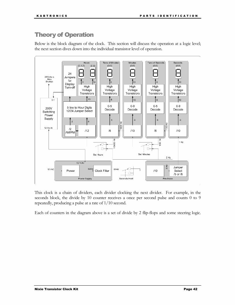
Below is the block diagram of the clock. This section will discuss the operation at a logic level; the next section dives down into the individual transistor level of operation.
This clock is a chain of dividers, each divider clocking the next divider. For example, in the seconds block, the divide by 10 counter receives a once per second pulse and counts 0 to 9 repeatedly, producing a pulse at a rate of 1/10 second.
Each of counters in the diagram above is a set of divide by 2 flip-flops and some steering logic.

K A B T R O N I C S P A R T S I D E N T I F I C A T I O N
Nixie Transistor Clock Kit Page 43
Low level logic
A single flip-flop counts to two (0, 1). Two flip-flops chained by connecting a Q output to the clock input of the next would count to four (0,1,2,3). Three flip-flops count to eight and four flip-flops count to 16. So how do we count to 10? The clocks must be controlled by logic gates as shown below.
Two kinds of logic gates will be needed to drive these counter chains; And gates and Or gates.
The And gate is high when both inputs are high and low otherwise.
The Or gate is high when either input is high and low when both are low.
These gates can be combined to form more complex logic functions as you will see on the next page.
The next figure is the logic chart for a divide by ten counter, or decade counter.

K A B T R O N I C S P A R T S I D E N T I F I C A T I O N
Nixie Transistor Clock Kit Page 44
Counter
Looking at the logic chart, you can see that the clock for the Q0 flip-flop can be a direct connection to the input clock to the decade counter. Also, the clock for the Q2 flip-flop can be a direct connection to Q1.
The clock for the Q1 flip-flop is very similar to the Q0 output, but one pulse at the 9 count needs to be removed, or masked, at the count of 9. Using an And gate with Q0 and the inverse of Q3 does the trick.
The clock for the Q3 flip-flop, which is the bottom line of the figure above, looks like Q2 for the first 8 counts (0-7) and Q0 for counts 8 and 9. A selector driven by Q3 does this.
The 4 to 10 line decoder uses Q0 to Q3, and their inverses, to select one of the ten output lines.

K A B T R O N I C S P A R T S I D E N T I F I C A T I O N
Nixie Transistor Clock Kit Page 45
The low voltage power supply section, in addition to rectifying the 12 volts AC power, also extracts the 60 Hz signal that is fed into the prescaler.
One side of the bridge rectifier is compared with 6 volts resulting in a pulse train repeating at 60 Hz. The pulse train edge detected and drives a switch that discharges a capacitor at a 60 Hz rate. The capacitor charges at a rate just fast enough to trip the last comparator to form a square wave at 60 Hz.
The whole reason to go through this complicated path is so that if noise enters the system from the power line and triggers the first comparator faster than 60 Hz, the result is the capacitor is discharged before it has charged up to trip the final comparator. Therefore instead of the noise causing the clock count extra and advance beyond the correct time, the output stays low. Noise is usually a short term set of pulses, far shorter than a cycle of 60 Hz, so often the noise pulse will only shorten one pulse, causing no error. This is in effect a brick wall low pass filter with about a 120 Hz cutoff.

K A B T R O N I C S P A R T S I D E N T I F I C A T I O N
Nixie Transistor Clock Kit Page 46
High Voltage Power Supply
The oscillator sets the latch, turning on the inductor charge switch. When the current reaches 2 amps, the latch is reset, turning off the switch. The inductor current then charges the capacitor raising the voltage slightly. When many of these cycles have raised the voltage of the capacitor to 180 Volts, the 180 volt detector holds the latch in reset preventing further operation until the capacitor voltage falls to under 180 volts.
The details will be explained in the component level descriptions.

K A B T R O N I C S P A R T S I D E N T I F I C A T I O N
Nixie Transistor Clock Kit Page 47
Circuit Description
The previous section described the clock functionality at the logic level; this section will descend to the transistor level.
First some basics:
A voltage potential placed across a resistance will cause a current to flow.
When a voltage is placed across an R C circuit with a discharged capacitor, the full voltage is across the resistor, but as the capacitor charges, the voltage across the resistor decreases to zero, at which point the capacitor has the full voltage across it. The time it takes is a function of the value of R and C.
Diodes will allow a current to pass in one direction with a small voltage drop when conducting.

K A B T R O N I C S P A R T S I D E N T I F I C A T I O N
Nixie Transistor Clock Kit Page 48
Current will not flow through a diode in the reverse direction. In this case the full 12 volts is across the reverse biased diode and the resistor has 0 volts across it.
Transistors look like a pair of diodes with a trick – when current flows through the emitter diode, current will flow through the reversed biased collector diode, up to β times the current in emitter diode. The β factor is about 50 for the transistors in this kit.
In this circuit, if the input is above 0.7 volts, a current will flow into the base and out the emitter. The output will be pulled down by the current flowing into the collector (β times the base current). That collector current will cause a voltage to be developed across the collector resistor. For example 1.7 volts would cause 0.1 milliamp in the base, and cause the collector to pull down with up to 5 milliamps of drive. In this case, 1.2 milliamp will pull the 10K down to ground.
In this bi-stable circuit, if Output A has a voltage on it, current flows into the base of Q2, which holds Output B low, keeping Q1 off and Output A at about 6 volts. This circuit is also stable with B at 6 volts and A at 0 volts. This circuit forms the basis of the flip-flop.

K A B T R O N I C S P A R T S I D E N T I F I C A T I O N
Nixie Transistor Clock Kit Page 49
This is a bi-stable circuit with a trigger input. Assume Q1 is on, A is low, and B is high. If the trigger is pulsed slightly below zero, the base current Q1 is removed for a moment. at which point the collector of Q1 (Output A) starts to rise. That rising voltage causes a current to flow into the base of Q2 causing output B to fall. A falling B also removes the current from the base of Q1, so the pulse can be removed, and the circuit toggles to the other state.
This circuit produces pulses on the falling edge. These pulses can be used to toggle the flip-flops above.
Here is an And gate, both inputs need to be high to make the output go high.

K A B T R O N I C S P A R T S I D E N T I F I C A T I O N
Nixie Transistor Clock Kit Page 50
This is an And-Or gate. The output is;
(A and B) or (C and D)
This is used to build the selector in the counter sections.
This is a differential amplifier. Assume A is at 5 volts and B is at 6 volts. The emitters are at 5.6 volts, transistor A is on, all the current from the resistor (0.64 mA) flows through collector A and none flows through collector B.
Assume A is at 5 volts. B is at 6 volts, the emitter current flows through Q1 and Q3. Q2 and Q4 are off. As input A rises, when it reaches 6 volts, the emitter current switches to Q2, turning on Q4, which slightly lowers point B. This feedback snaps the comparator into the new state. Q3 turns off providing the output.

K A B T R O N I C S P A R T S I D E N T I F I C A T I O N
Nixie Transistor Clock Kit Page 51
This is an inductor. The voltage across an inductor is proportional to the change of the current passing through it. That works both ways, forcing a voltage across an inductor causes the current to change proportional to the voltage and the inductance.
For this 220 uHenry part, 12 volts causes the current to increase by 54 thousand amps per second. (12/0.00022) or 54 mAmps per uSecond. Note it takes about 18 uSeconds to reach 2 amps.
When the switch closes, the current builds, reaching 2 amps in 18 uSeconds. The switch opens, the voltage across the inductor rises to 180 volts, the diode turns on, the current runs into the capacitor, decaying at a new faster rate, 180V/220uH= 910mA per uSecond, so in 2.2 uSeconds the current is back to 0.
Each pulse of current places a small amount of energy into the capacitor. Energy in an inductor (really the magnetic field about it) is E=1/2 L I2
In this example of 2 amps and 200uH the energy per pulse is 440 uJoules.
The energy in a capacitor is E = 1/2 C V2 . At 180V, the 120uF capacitor holds 2.4 Joules It takes 5454 inductor pulses to charge the capacitor to 180V. At 180V, a single cycle of the switch, 440 uJoules, increases the voltage by about 18 mV

K A B T R O N I C S P A R T S I D E N T I F I C A T I O N
Nixie Transistor Clock Kit Page 52
Th
e A
C v
olt
age
is
rect
ifie
d in
th
is
bri
dge
. O
ne
leg
is
tap
ped
off
to
a
com
par
ato
r.
Th
is c
om
par
ato
r is
co
mp
arin
g th
e 6
volt
s o
n t
he
righ
t to
th
e b
rid
ge le
g vo
ltag
e.
Th
is c
ircu
it c
reat
es a
puls
e o
n
the
neg
ativ
e go
ing
edge
of
the
com
par
ato
r o
utp
ut a
nd
d
isch
arge
s th
e ca
pac
ito
r
Th
is s
eco
nd
com
par
ato
r is
co
mp
arin
g th
e vo
ltag
e of
the
cap
acit
or
and 6
vo
lts.
Th
ese
are
byp
ass
cap
acit
ors
sp
read
ab
out
the
bo
ard
Th
is is
th
e 68
00 u
F
elec
tro
lyti
c ca
pac
ito
r

K A B T R O N I C S P A R T S I D E N T I F I C A T I O N
Nixie Transistor Clock Kit Page 53
Th
is is
th
e 1s
t to
ggle
flip
-fl
ip, i
t is
clo
cked
fro
m t
he
pre
vio
us
pag
e.
Th
is is
an
An
d g
ate
that
is
con
nec
t to
th
e in
vert
ed o
up
ut
of
the
4th f
lip-f
lop
. W
hen
th
e co
un
t re
ach
es 8
, th
e N
QC
_3
line
goes
low
mas
kin
g o
ff t
he
puls
e at
coun
t 9.
Th
is is
th
e 2n
d f
lip-f
lop
. It
is c
lock
ed b
y th
e A
nd
gat
e.
Th
is is
th
e 3r
d f
lip-f
lop
.
It is
clo
cked
dir
ectl
y fr
om
th
e 2n
d f
lip-f
lop
.
Th
is is
an
An
d-O
r ga
te u
sed
to
add
a
puls
e at
th
e 9t
h
coun
t as
sh
ow
n in
th
e th
eory
of
op
erat
ion
sec
tio
n
Th
is is
th
e fo
urt
h
flip
-flo
p.
It is
cl
ock
ed b
y fr
om
the
An
d-O
r ga
te

K A B T R O N I C S I N C A S E O F D I F F I C U L T Y
Nixie Transistor Clock Kit Page 54
In Case of Difficulty
General Troubleshooting
The most useful tool you have when troubleshooting is your brain.
Start with the data showing the problem. If one of the displays is not counting properly, stop and think about it.
How is it counting?
• Is it changing at all? (this will tell you if the input clock is present)
• Is it changing at the right rate? (this will tell you if the clock to the counter is at the right frequency)
• Is it going through the proper number of states, even if the numbers displayed are wrong? (this will hint if the problem is in the decode/display area or the counter)
• Is it displaying only proper numbers, or are there odd characters and blanks showing? (this will hint at problems in 1-of-n decode or 7-segment decode)
A problem in the logic section will cause the counter to cycle in the wrong number of states. A problem in the decode section can feed back to the counter and cause the counter to skip states. A problem in the 7-segment decode should only affect the displayed digits, not the counter. Make a most likely guess at the problem, then gather more data to either support or refute your guess. Repeat until you find the problem. This list is my guess at the cause of any problem in decreasing order of probability;
• Wrong component loaded
• Component loaded backwards
• Bad solder joint causing open or short to adjacent pad
• A clipped-off lead has stuck to the back of the board and is shorting out the circuit
• The board is resting on something conductive shorting out the circuit
• A component is bad because;
o it was over heated when soldered (medium chance)
o came that way with the kit (low chance)
o was damaged by static electricity when handled (unlikely)
• The PC board is damaged or was fabricated incorrectly (very unlikely) So take a close look at the back of the board looking for bad solder joints and clipped leads in the area of the problem. Check for proper components and orientations. If you haven’t found the problem, continue onto the specific trouble shooting section below, which will walk you through troubleshooting a section.
K A B T R O N I C S I N C A S E O F D I F F I C U L T Y
Nixie Transistor Clock Kit Page 55
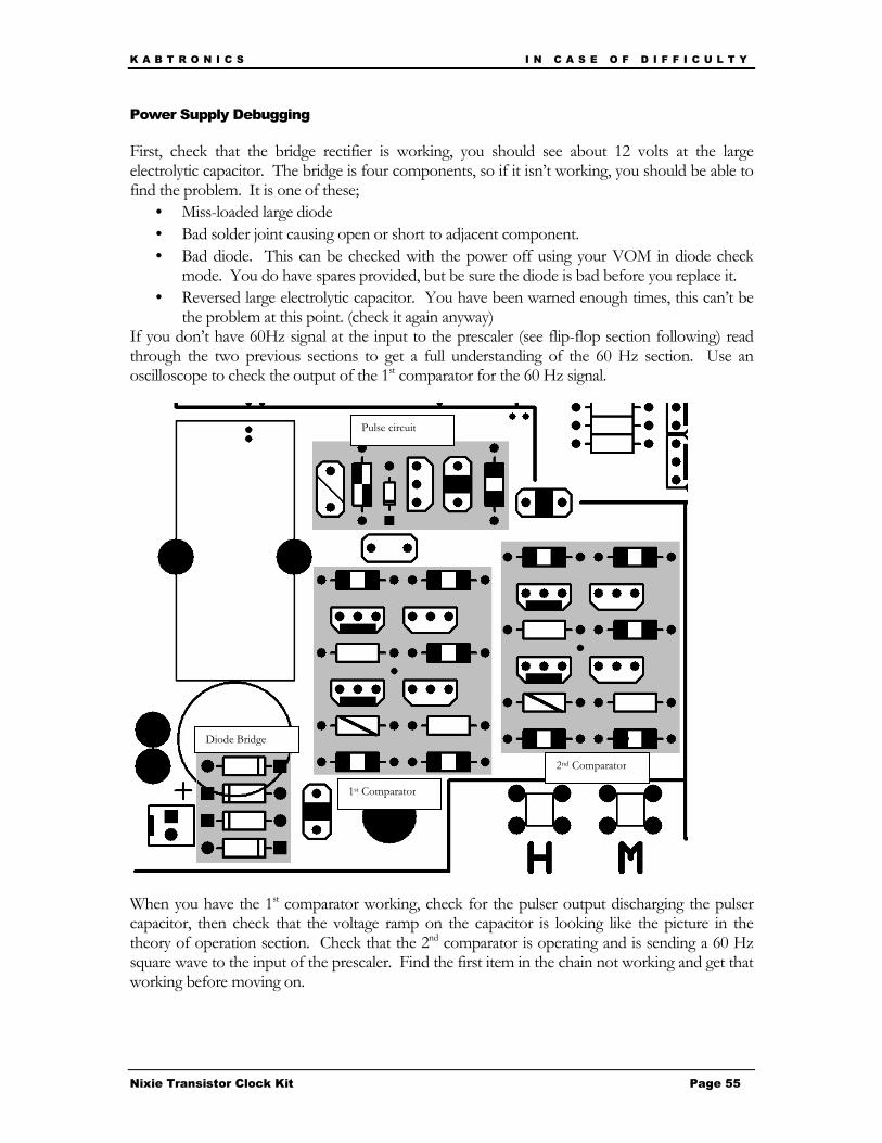
Power Supply Debugging
First, check that the bridge rectifier is working, you should see about 12 volts at the large electrolytic capacitor. The bridge is four components, so if it isn’t working, you should be able to find the problem. It is one of these;
• Miss-loaded large diode
• Bad solder joint causing open or short to adjacent component.
• Bad diode. This can be checked with the power off using your VOM in diode check mode. You do have spares provided, but be sure the diode is bad before you replace it.
• Reversed large electrolytic capacitor. You have been warned enough times, this can’t be the problem at this point. (check it again anyway)
If you don’t have 60Hz signal at the input to the prescaler (see flip-flop section following) read through the two previous sections to get a full understanding of the 60 Hz section. Use an oscilloscope to check the output of the 1st comparator for the 60 Hz signal.
When you have the 1st comparator working, check for the pulser output discharging the pulser capacitor, then check that the voltage ramp on the capacitor is looking like the picture in the theory of operation section. Check that the 2nd comparator is operating and is sending a 60 Hz square wave to the input of the prescaler. Find the first item in the chain not working and get that working before moving on.
Diode Bridge
1st Comparator
2nd Comparator
Pulse circuit
K A B T R O N I C S I N C A S E O F D I F F I C U L T Y
Nixie Transistor Clock Kit Page 56
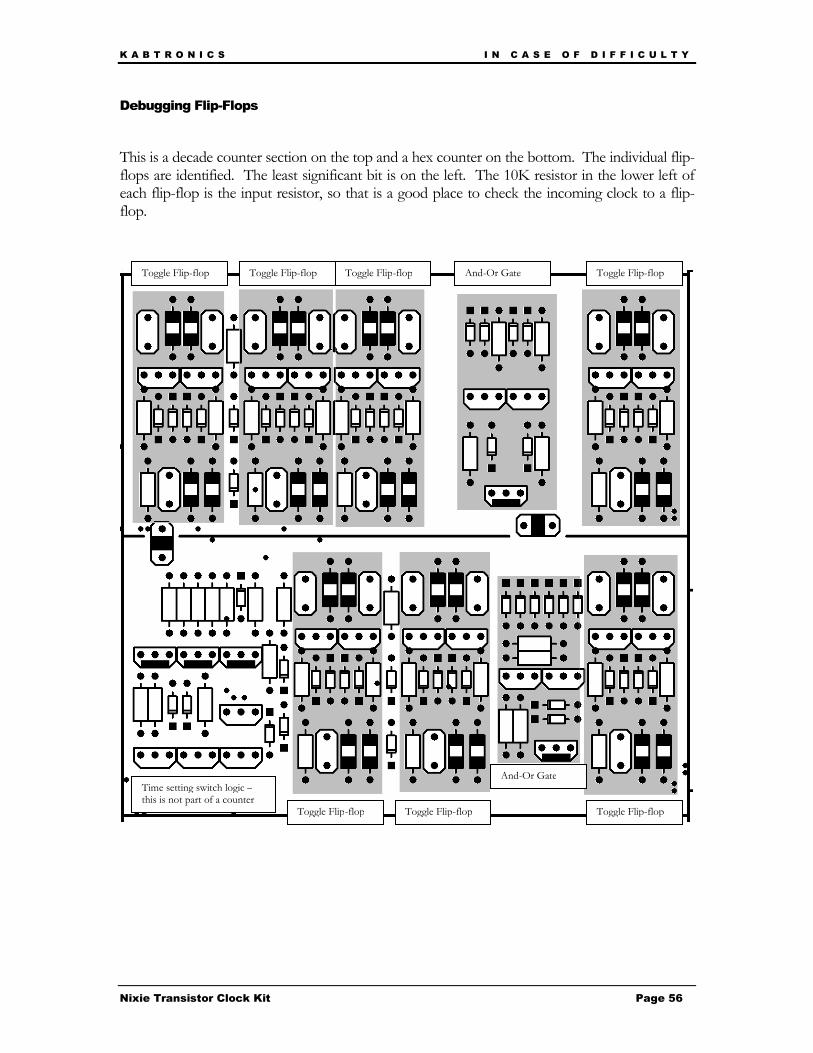
Debugging Flip-Flops
This is a decade counter section on the top and a hex counter on the bottom. The individual flip-flops are identified. The least significant bit is on the left. The 10K resistor in the lower left of each flip-flop is the input resistor, so that is a good place to check the incoming clock to a flip-flop.
add trouble shooting guide
Toggle Flip-flop Toggle Flip-flop Toggle Flip-flop Toggle Flip-flop
Toggle Flip-flop Toggle Flip-flop Toggle Flip-flop
And-Or Gate
And-Or Gate Time setting switch logic – this is not part of a counter

K A B T R O N I C S I N C A S E O F D I F F I C U L T Y
Nixie Transistor Clock Kit Page 57
The basics of flip-flop troubleshooting are;
• Find the last working flip-flop in the chain.
• Check if the input to the bad flip-flop is toggling. The input to each flip-flop on the 10K resistor on the lower left of a flip-flop.
• Check if the components are correctly placed and oriented.
• Check if the solder joints are good and that there isn’t excess solder or leads shorting out the circuit on the bottom.
• Check if the decoder circuit being driven by this flip-flop is correct, a problem in the decoder can affect the flip-flop. Really check this out, if it isn’t one of the above problems, you are running out of possibilities.
If you haven’t found the problem by this point, you will need to use your oscilloscope to compare a working flip-flop with the bad flip flop. Look at the base of each transistor to see if the voltage is looking normal. (You can see normal from the working flip-flop). There aren’t many other nodes in a flip-flop, the outputs, the bases, and the output of the pulser feeding the toggle diodes.
You will find that the flip-flops are very sensitive, touching an output with your scope lead can trigger the flip-flop to change, at first you may not realizes that and think that both outputs are low, when in fact the flip-flop is changing as you move the scope lead. Also, this sensitivity can be an issue when you are handling the board during testing, it can be affected by your fingers. You can’t hurt the circuit, but it may not count right while you are touching the board.
If the display is changing with each count, but the value is wrong, for example the counter is counting 2,5,2,5 or 0,1,2,blank,0,1,2,blank your problem is probably in the logic section for that counter.
If you just can’t find the problem, start to suspect a bad diode or transistor, the chance is small, but if you have checked everything else you may be out of possibilities. You should be able to spot a bad diode or transistor by bad voltages on one of the nodes, don’t go swapping out parts without seeing some evidence first.

K A B T R O N I C S I N C A S E O F D I F F I C U L T Y
Nixie Transistor Clock Kit Page 58
Debugging Decoders
The 10 decoders are highlighted below. The four diodes on the left of each transistor pair decode the state. Only one decoder should be “on” and pulling low on its select line. There are 10 select lines from the decoders on the right going to the field of diodes on the left. If you see odd characters or numbers blended together, suspect a short between select lines. If you see blanks among the digits displays when counting, the decoder for the blank state may be failing.
Problems in the decoder can easily feed back to the counters and cause them to miscount.

K A B T R O N I C S S P E C I F I C A T I O N S
Nixie Transistor Clock Kit Page 59
Specifications
PC board Size: 10 inches wide by 14 inches high
(Allow ¼ inch behind board and 1.5 inches above when loaded for parts clearance)
Weight: About 20 oz, (add 17 oz for wall transformer)
Power consumption: About 14.4 watts, (1.2 amps @ 12 volts AC)
Temperature limits: Designed for room temperature operation, 60-80 °F
Longevity: The electrolytic capacitors will eventually dry out as the liquid gradually leaks out the pressure vent, you may need to replace them in 5 or 15 years. The Nixie Tube displays will fail; portions of the segments will fail to light as contaminants coat the numerals; the Nixie Tubes are in sockets. The large diodes may fail at some point, they are working hard. Any of these items can be easily replaced by you.
Warrantee: There is no warrantee of any kind. KABtronics wants you to succeed and be happy with your clock, so don’t hesitate to email [email protected] with questions if you are having difficulty.

K A B T R O N I C S C I R C U I T B O A R D V I E W
Nixie Transistor Clock Kit Page 60
Circuit Board Views
Silk Screen

K A B T R O N I C S C I R C U I T B O A R D V I E W
Nixie Transistor Clock Kit Page 61
Top Copper Layer

K A B T R O N I C S C I R C U I T B O A R D V I E W
Nixie Transistor Clock Kit Page 62
Bottom Copper Layer

K A B T R O N I C S
Nixie Transistor Clock Kit Page 63
Schematic

K A B T R O N I C S
Nixie Transistor Clock Kit Page 64

K A B T R O N I C S
Nixie Transistor Clock Kit Page 65

K A B T R O N I C S
Nixie Transistor Clock Kit Page 66
K A B T R O N I C S
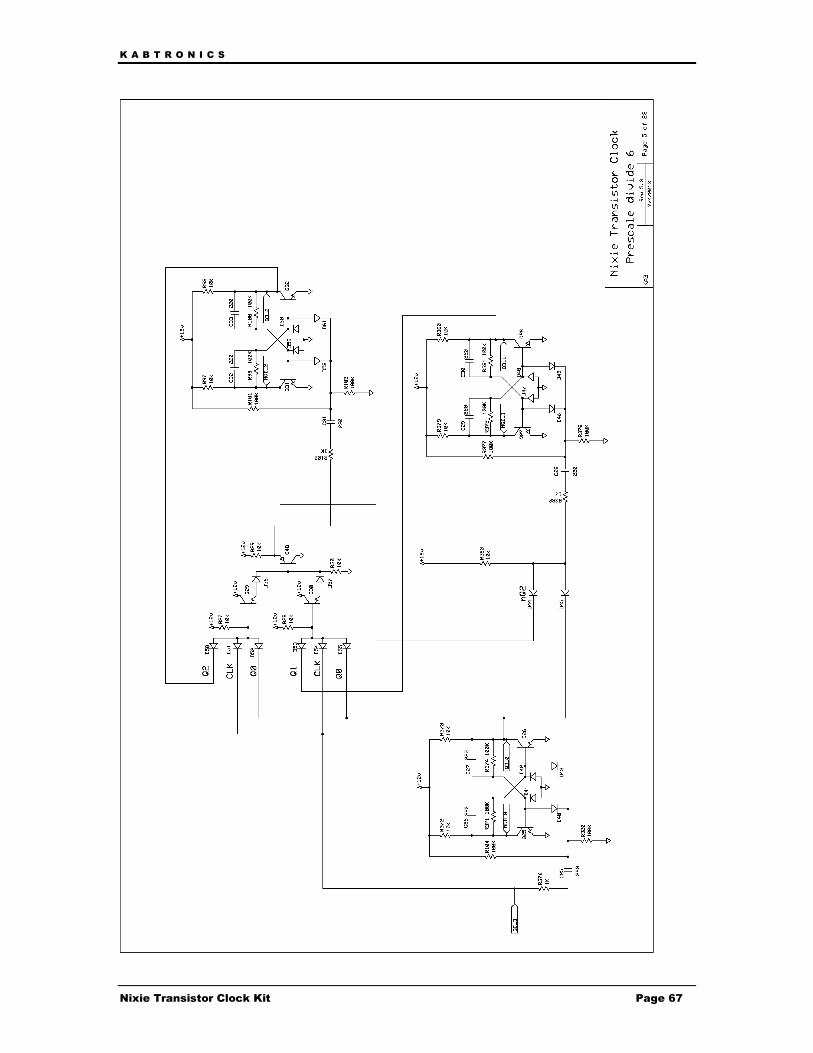
Nixie Transistor Clock Kit Page 67

K A B T R O N I C S
Nixie Transistor Clock Kit Page 68

K A B T R O N I C S
Nixie Transistor Clock Kit Page 69

K A B T R O N I C S
Nixie Transistor Clock Kit Page 70

K A B T R O N I C S
Nixie Transistor Clock Kit Page 71

K A B T R O N I C S
Nixie Transistor Clock Kit Page 72

K A B T R O N I C S
Nixie Transistor Clock Kit Page 73
K A B T R O N I C S
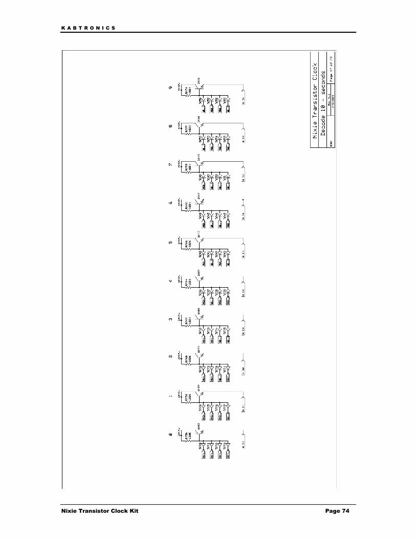
Nixie Transistor Clock Kit Page 74

K A B T R O N I C S
Nixie Transistor Clock Kit Page 75

K A B T R O N I C S
Nixie Transistor Clock Kit Page 76

K A B T R O N I C S
Nixie Transistor Clock Kit Page 77

K A B T R O N I C S
Nixie Transistor Clock Kit Page 78

K A B T R O N I C S
Nixie Transistor Clock Kit Page 79

K A B T R O N I C S
Nixie Transistor Clock Kit Page 80

K A B T R O N I C S
Nixie Transistor Clock Kit Page 81

K A B T R O N I C S
Nixie Transistor Clock Kit Page 82

K A B T R O N I C S
Nixie Transistor Clock Kit Page 83

K A B T R O N I C S
Nixie Transistor Clock Kit Page 84

K A B T R O N I C S
Nixie Transistor Clock Kit Page 85

K A B T R O N I C S
Nixie Transistor Clock Kit Page 86
Component Silk Screen symbol

K A B T R O N I C S
Nixie Transistor Clock Kit Page 87