manual - nixie neon retro nixie · 2018-02-07manual - nixie neon retro nixie clock
TRANSCRIPT
NixieNeonAssembly Manual
http://www.nixieneon.com10-09-2016
Nixie Neon Assembly Manual Pg 3
CroftJ Internet Services
Nixie Neon Assembly Manual Pg 4
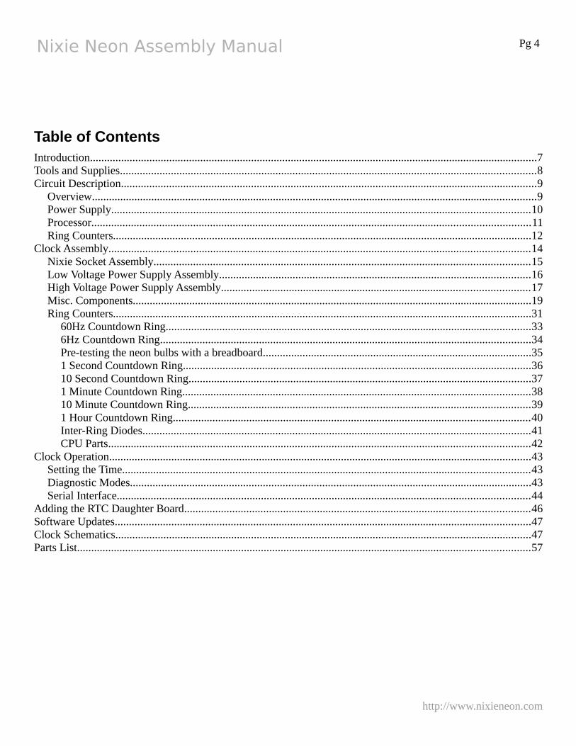
Table of ContentsIntroduction..............................................................................................................................................................7Tools and Supplies...................................................................................................................................................8Circuit Description...................................................................................................................................................9
Overview.............................................................................................................................................................9Power Supply....................................................................................................................................................10Processor...........................................................................................................................................................11Ring Counters....................................................................................................................................................12
Clock Assembly.....................................................................................................................................................14Nixie Socket Assembly.....................................................................................................................................15Low Voltage Power Supply Assembly..............................................................................................................16High Voltage Power Supply Assembly.............................................................................................................17Misc. Components.............................................................................................................................................19Ring Counters....................................................................................................................................................31
60Hz Countdown Ring.................................................................................................................................336Hz Countdown Ring...................................................................................................................................34Pre-testing the neon bulbs with a breadboard...............................................................................................351 Second Countdown Ring...........................................................................................................................3610 Second Countdown Ring.........................................................................................................................371 Minute Countdown Ring...........................................................................................................................3810 Minute Countdown Ring.........................................................................................................................391 Hour Countdown Ring..............................................................................................................................40Inter-Ring Diodes.........................................................................................................................................41CPU Parts.....................................................................................................................................................42
Clock Operation.....................................................................................................................................................43Setting the Time................................................................................................................................................43Diagnostic Modes..............................................................................................................................................43Serial Interface..................................................................................................................................................44
Adding the RTC Daughter Board..........................................................................................................................46Software Updates...................................................................................................................................................47Clock Schematics...................................................................................................................................................47Parts List................................................................................................................................................................57
http://www.nixieneon.com
Nixie Neon Assembly Manual Pg 5
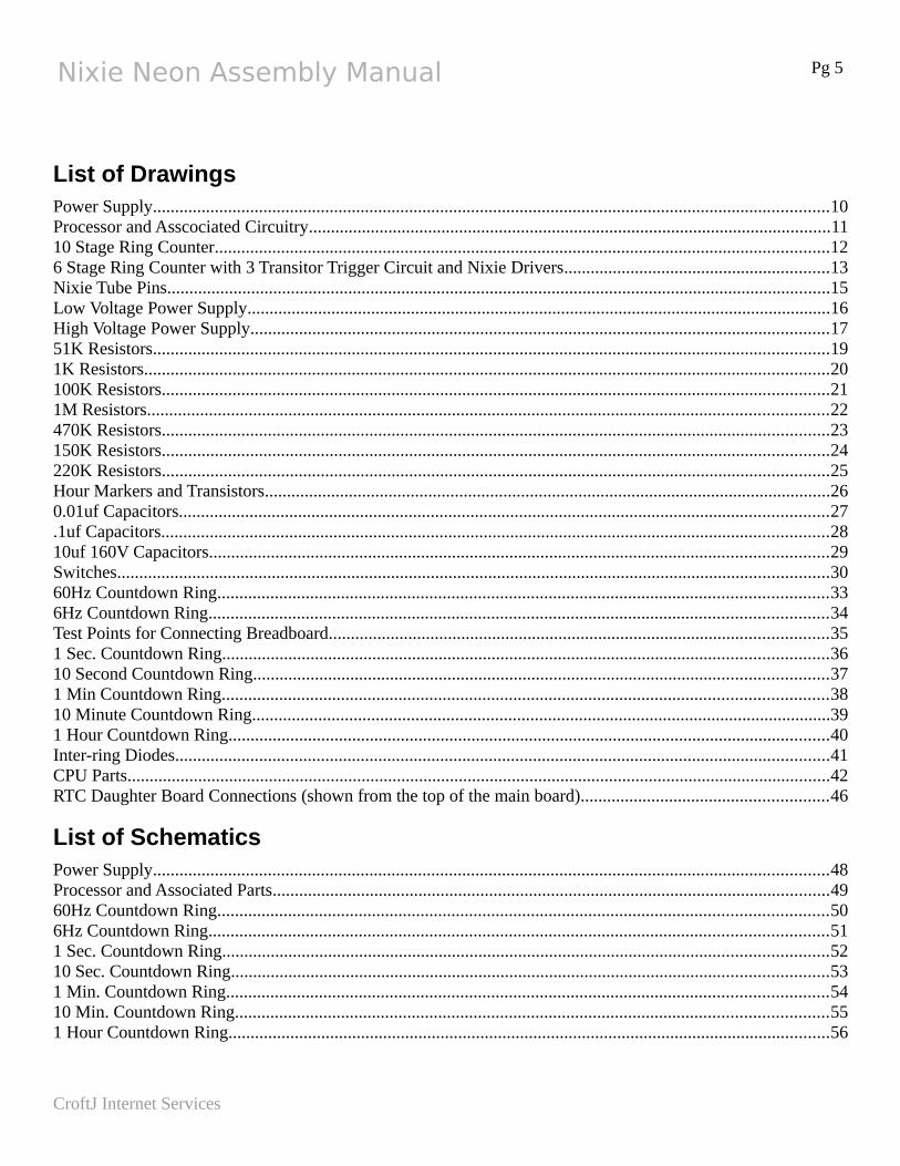
List of DrawingsPower Supply.........................................................................................................................................................10Processor and Asscociated Circuitry......................................................................................................................1110 Stage Ring Counter...........................................................................................................................................126 Stage Ring Counter with 3 Transitor Trigger Circuit and Nixie Drivers............................................................13Nixie Tube Pins......................................................................................................................................................15Low Voltage Power Supply....................................................................................................................................16High Voltage Power Supply...................................................................................................................................1751K Resistors.........................................................................................................................................................191K Resistors...........................................................................................................................................................20100K Resistors.......................................................................................................................................................211M Resistors..........................................................................................................................................................22470K Resistors.......................................................................................................................................................23150K Resistors.......................................................................................................................................................24220K Resistors.......................................................................................................................................................25Hour Markers and Transistors................................................................................................................................260.01uf Capacitors...................................................................................................................................................27.1uf Capacitors.......................................................................................................................................................2810uf 160V Capacitors............................................................................................................................................29Switches.................................................................................................................................................................3060Hz Countdown Ring..........................................................................................................................................336Hz Countdown Ring............................................................................................................................................34Test Points for Connecting Breadboard.................................................................................................................351 Sec. Countdown Ring.........................................................................................................................................3610 Second Countdown Ring..................................................................................................................................371 Min Countdown Ring.........................................................................................................................................3810 Minute Countdown Ring...................................................................................................................................391 Hour Countdown Ring........................................................................................................................................40Inter-ring Diodes....................................................................................................................................................41CPU Parts...............................................................................................................................................................42RTC Daughter Board Connections (shown from the top of the main board)........................................................46
List of SchematicsPower Supply.........................................................................................................................................................48Processor and Associated Parts..............................................................................................................................4960Hz Countdown Ring..........................................................................................................................................506Hz Countdown Ring............................................................................................................................................511 Sec. Countdown Ring.........................................................................................................................................5210 Sec. Countdown Ring.......................................................................................................................................531 Min. Countdown Ring........................................................................................................................................5410 Min. Countdown Ring......................................................................................................................................551 Hour Countdown Ring........................................................................................................................................56
CroftJ Internet Services

Nixie Neon Assembly Manual Pg 6
http://www.nixieneon.com
Nixie Neon Assembly Manual Pg 7
IntroductionThe Nixie Neon was born out of a love for clocks and electronics. My hope was to find a design which would let you actually see the time keeping. Where the lights were actually doing the time keeping and not just indicators. The years passed and while surfing the Net I discovered Neon Ring Counters with a site describing a clock using them. Further searching provided me with a copy of the GE Neon Glow Lamp manual. My clock was born!
My original plan was not to have a processor on this clock. Sadly, though some of the original clocks are still functioning well, many have a had bulb or two start fire erratically which causes the clock to mis-count. This is where the processor comes in. Though it does not directly run the rings in normal operation, it can sequence any of the rings to help detect flaky bulbs. It also adds a pendulum of sorts by flashing the neon bulbs usedas the hour markers. Also, if desired, it will reset the clock to the time that the processor has, which is determined by counting the AC cycles of the wall current.
With over 400 components, this cannot be considered an easily assembled kit. This manual is the product of assembling several clocks and formulating the easiest order andtechniques for assembling a working clock. Please familiarize yourself with the entire manual before you begin assembling the clock.
One can expect it to take about 6 or 7 hours to assemble the clock.
Important NoteThere have bean some changes to the high voltage circuit which have not made
it to the PCB. These and the associate changes to the building procedure are noted by boxes such as this labeled Circuit Changes!
CroftJ Internet Services
Nixie Neon Assembly Manual Pg 8
Tools and Supplies
CautionDo not use water soluble flux core solder. It is just conductive enough, to make
testing and trouble shooting the clock during assembly quite difficult.
The following tools and supplies are required to build this clock:
• Wire Cutters
• Needle Nose Pliers
• Soldering Iron
• Rosin Core Solder
• Solder Sucker
The following are optional:
• Solderless Breadboard with 630 + 200 Tie Points
http://www.nixieneon.com
Nixie Neon Assembly Manual Pg 9
Circuit Description
Overview
The clock is comprised of a low voltage supply, a high voltage supply and 2 ring counters. The low power supply converts the 12VAC from the wall wart into roughly 15 volts and 5 volts to drive the high voltage supply. The high voltage supply generates 120V to drive the ring counters and 160V to drive the nixie tubes. The ring counters count the 60Hz from the wall current down to hours. To accomplish this there are three basic ring counters configurations in use. A 10 stage ring counter, a 6 stage ring counter and a 12 stage ring counter.
The 3 of each of the 10 stage and 6 stage ring counters are paired together to generate 1 second pulses, 1 minute pulse and 1 hour pulses. The last ring counter has 12 stages and counts the hours. While the actual ring circuits are the same, each of the pair of ring counters have have something unique about them. The first pair uses a simple single transistor triggering circuit which is capacitive coupled to the ring. This trigger circuit was too sensitive to noise for the latter ring counters so they have a three transistor trigger circuit.
The pair of ring counters which count the minutes have transistors incorporated into their circuit to drive the cathodes of nixie tubes. Because of the circuit layout, the stageswith the diode connected to ground, has had the diodes replaced with the base emitter junction of a transistor. The other stages with the resistor tied to ground drives a transistor through a 220K resistor.
CroftJ Internet Services
Nixie Neon Assembly Manual Pg 10
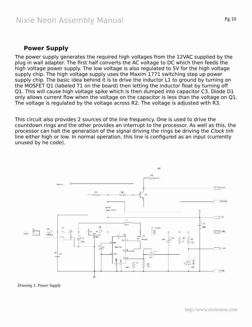
Power Supply
The power supply generates the required high voltages from the 12VAC supplied by the plug in wall adapter. The first half converts the AC voltage to DC which then feeds the high voltage power supply. The low voltage is also regulated to 5V for the high voltage supply chip. The high voltage supply uses the Maxim 1771 switching step up power supply chip. The basic idea behind it is to drive the inductor L1 to ground by turning on the MOSFET Q1 (labeled T1 on the board) then letting the inductor float by turning off Q1. This will cause high voltage spike which is then dumped into capacitor C3. Diode D1 only allows current flow when the voltage on the capacitor is less than the voltage on Q1.The voltage is regulated by the voltage across R2. The voltage is adjusted with R3.
This circuit also provides 2 sources of the line frequency. One is used to drive the countdown rings and the other provides an interrupt to the processor. As well as this, theprocessor can halt the generation of the signal driving the rings be driving the Clock Inh line either high or low. In normal operation, this line is configured as an input (currently unused by he code).
http://www.nixieneon.com
Drawing 1: Power Supply
Nixie Neon Assembly Manual Pg 11
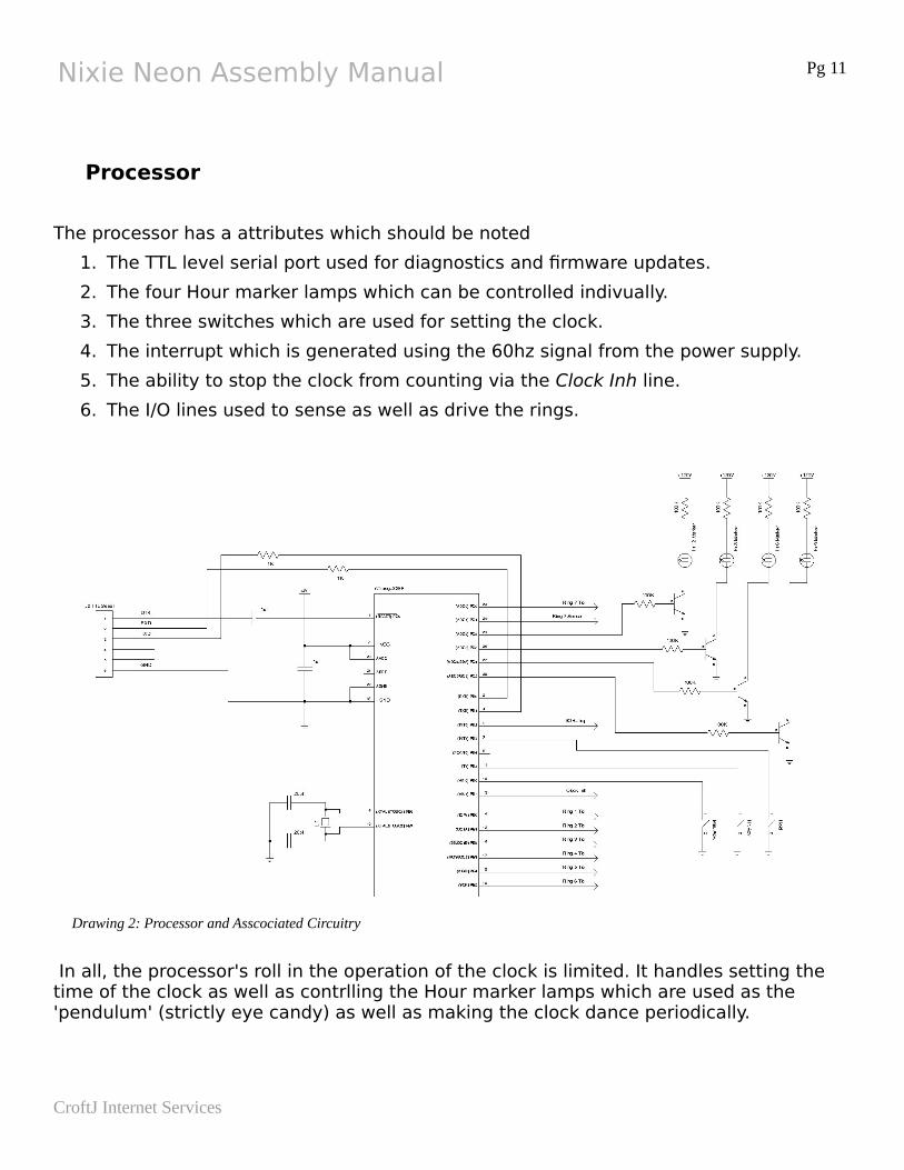
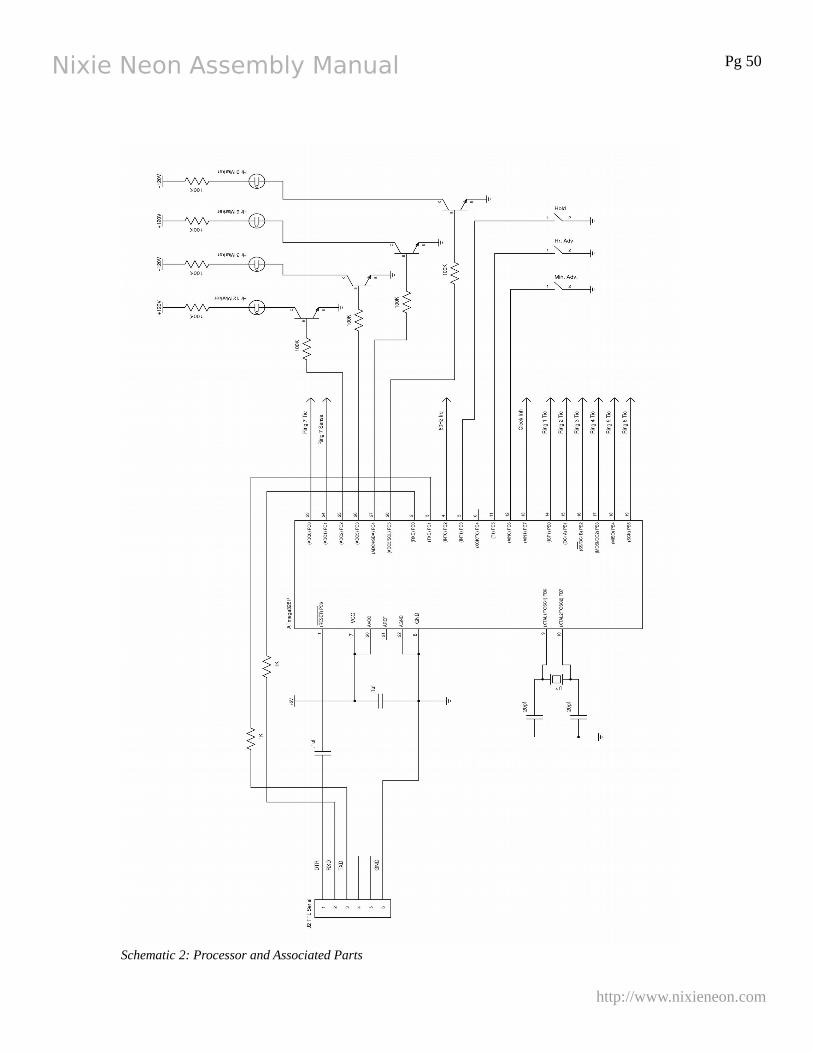
Processor
The processor has a attributes which should be noted
1. The TTL level serial port used for diagnostics and firmware updates.
2. The four Hour marker lamps which can be controlled indivually.
3. The three switches which are used for setting the clock.
4. The interrupt which is generated using the 60hz signal from the power supply.
5. The ability to stop the clock from counting via the Clock Inh line.
6. The I/O lines used to sense as well as drive the rings.
In all, the processor's roll in the operation of the clock is limited. It handles setting the time of the clock as well as contrlling the Hour marker lamps which are used as the 'pendulum' (strictly eye candy) as well as making the clock dance periodically.
CroftJ Internet Services
Drawing 2: Processor and Asscociated Circuitry
Nixie Neon Assembly Manual Pg 12
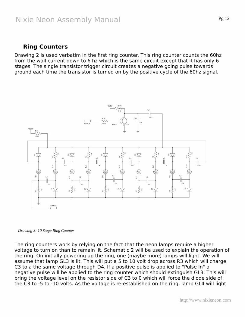
Ring Counters
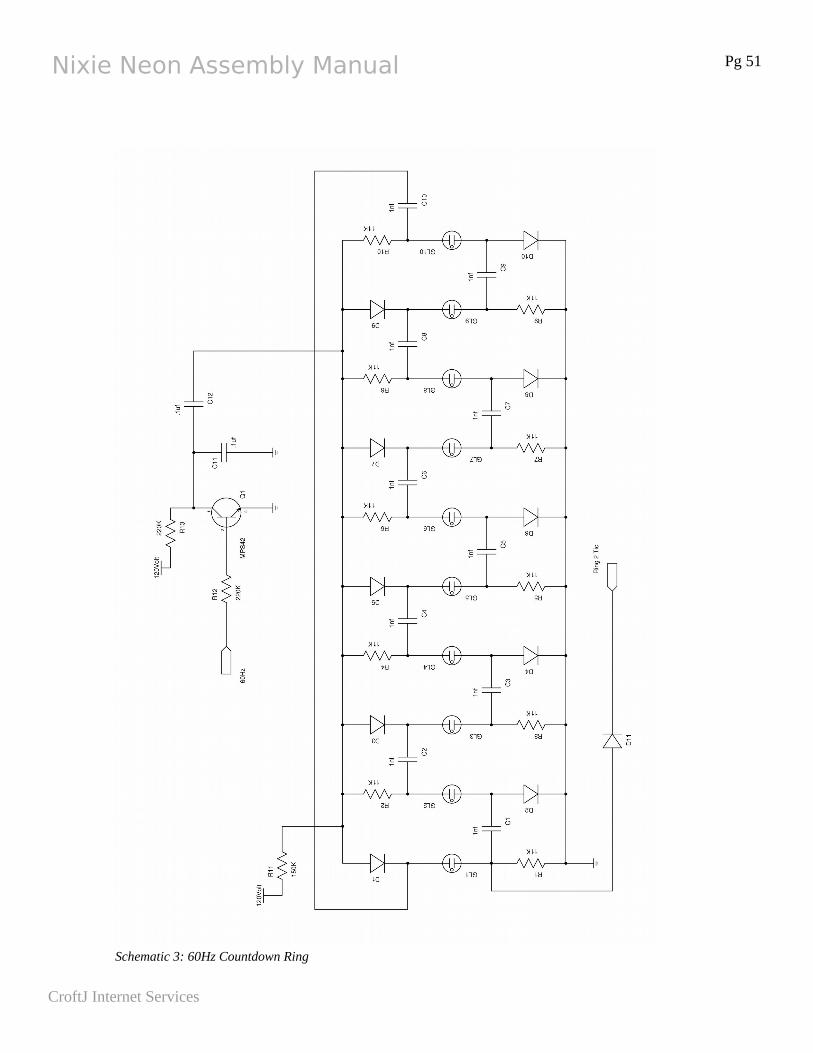
Drawing 2 is used verbatim in the first ring counter. This ring counter counts the 60hz from the wall current down to 6 hz which is the same circuit except that it has only 6 stages. The single transistor trigger circuit creates a negative going pulse towards ground each time the transistor is turned on by the positive cycle of the 60hz signal.
The ring counters work by relying on the fact that the neon lamps require a higher voltage to turn on than to remain lit. Schematic 2 will be used to explain the operation ofthe ring. On initially powering up the ring, one (maybe more) lamps will light. We will assume that lamp GL3 is lit. This will put a 5 to 10 volt drop across R3 which will charge C3 to a the same voltage through D4. If a positive pulse is applied to "Pulse In" a negative pulse will be applied to the ring counter which should extinguish GL3. This will bring the voltage level on the resistor side of C3 to 0 which will force the diode side of the C3 to -5 to -10 volts. As the voltage is re-established on the ring, lamp GL4 will light
http://www.nixieneon.com
Drawing 3: 10 Stage Ring Counter
Nixie Neon Assembly Manual Pg 13
up first because it will have the additional voltage of the capacitor as an advantage over the others. Once it lights, it will draw enough current through the 150K resistor R11 to lower the voltage on the ring down below the level that any of the other lamps will be able to light. The lighting of lamp GL4 will then charge C4 and the process will continue with each pulsing of "Pulse In". To cascade rings, "Pulse Out" can be taken from the lamp side of any of the 11K resistors which are tied to ground. It must not be loaded too heavily by the successive stage or its operation will be effected. One important thing to remember, as far as the overall clock is considered, the stage which is used for "Pulse Out" will be 0 for that ring. This is most important for the minutes and 10s of minutes rings.
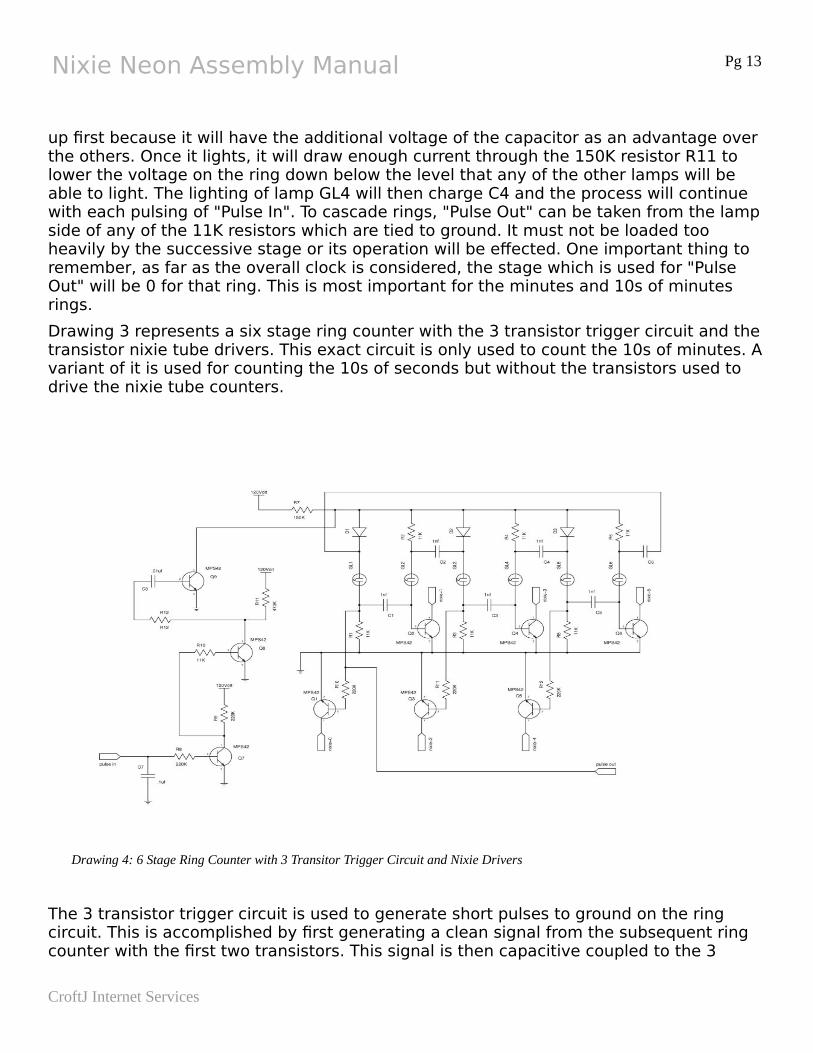
Drawing 3 represents a six stage ring counter with the 3 transistor trigger circuit and the transistor nixie tube drivers. This exact circuit is only used to count the 10s of minutes. Avariant of it is used for counting the 10s of seconds but without the transistors used to drive the nixie tube counters.
The 3 transistor trigger circuit is used to generate short pulses to ground on the ring circuit. This is accomplished by first generating a clean signal from the subsequent ring counter with the first two transistors. This signal is then capacitive coupled to the 3
CroftJ Internet Services
Drawing 4: 6 Stage Ring Counter with 3 Transitor Trigger Circuit and Nixie Drivers
Nixie Neon Assembly Manual Pg 14
transistor to generate a short pulse to ground which is directly applied to the ring counter.
Clock Assembly
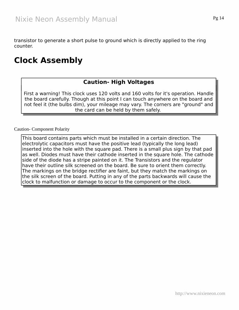
Caution- High Voltages
First a warning! This clock uses 120 volts and 160 volts for it's operation. Handlethe board carefully. Though at this point I can touch anywhere on the board andnot feel it (the bulbs dim), your mileage may vary. The corners are "ground" and
the card can be held by them safely.
Caution- Component Polarity
This board contains parts which must be installed in a certain direction. The electrolytic capacitors must have the positive lead (typically the long lead) inserted into the hole with the square pad. There is a small plus sign by that pad as well. Diodes must have their cathode inserted in the square hole. The cathode side of the diode has a stripe painted on it. The Transistors and the regulator have their outline silk screened on the board. Be sure to orient them correctly. The markings on the bridge rectifier are faint, but they match the markings on the silk screen of the board. Putting in any of the parts backwards will cause the clock to malfunction or damage to occur to the component or the clock.
http://www.nixieneon.com
Nixie Neon Assembly Manual Pg 15
Nixie Socket Assembly
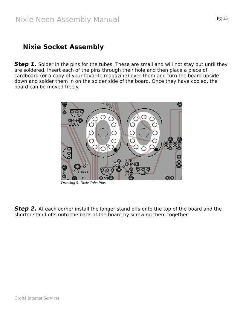
Step 1. Solder in the pins for the tubes. These are small and will not stay put until theyare soldered. Insert each of the pins through their hole and then place a piece of cardboard (or a copy of your favorite magazine) over them and turn the board upside down and solder them in on the solder side of the board. Once they have cooled, the board can be moved freely.
Step 2. At each corner install the longer stand offs onto the top of the board and the shorter stand offs onto the back of the board by screwing them together.
CroftJ Internet Services
Drawing 5: Nixie Tube Pins
Nixie Neon Assembly Manual Pg 16
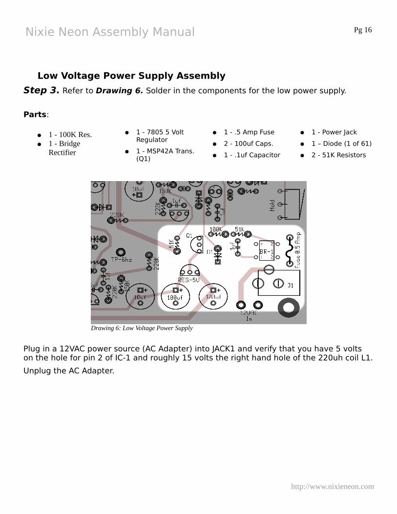
Low Voltage Power Supply Assembly
Step 3. Refer to Drawing 6. Solder in the components for the low power supply.
Parts:
● 1 - 100K Res.● 1 - Bridge
Rectifier
● 1 - 7805 5 Volt Regulator
● 1 - MSP42A Trans. (Q1)
● 1 - .5 Amp Fuse
● 2 - 100uf Caps.
● 1 - .1uf Capacitor
● 1 - Power Jack
● 1 – Diode (1 of 61)
● 2 - 51K Resistors
Plug in a 12VAC power source (AC Adapter) into JACK1 and verify that you have 5 volts on the hole for pin 2 of IC-1 and roughly 15 volts the right hand hole of the 220uh coil L1.
Unplug the AC Adapter.
http://www.nixieneon.com
Drawing 6: Low Voltage Power Supply
Nixie Neon Assembly Manual Pg 17
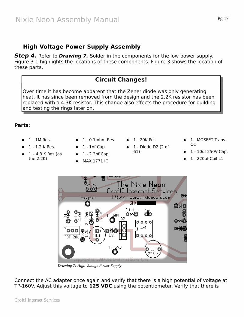
High Voltage Power Supply Assembly
Step 4. Refer to Drawing 7. Solder in the components for the low power supply. Figure 3-1 highlights the locations of these components. Figure 3 shows the location of these parts.
Circuit Changes!
Over time it has become apparent that the Zener diode was only generating heat. It has since been removed from the design and the 2.2K resistor has been replaced with a 4.3K resistor. This change also effects the procedure for building and testing the rings later on.
Parts:
● 1 - 1M Res.
● 1 - 1.2 K Res.
● 1 – 4.3 K Res.(as the 2.2K)
● 1 - 0.1 ohm Res.
● 1 - 1nf Cap.
● 1 - 2.2nf Cap.
● MAX 1771 IC
● 1 - 20K Pot.
● 1 - Diode D2 (2 of 61)
● 1 - MOSFET Trans. Q1
● 1 - 10uf 250V Cap.
● 1 - 220uf Coil L1
Connect the AC adapter once again and verify that there is a high potential of voltage at TP-160V. Adjust this voltage to 125 VDC using the potentiometer. Verify that there is
CroftJ Internet Services
Drawing 7: High Voltage Power Supply
Nixie Neon Assembly Manual Pg 18
about the same voltage at TP-120V. Unplug the AC Adapter.
http://www.nixieneon.com
Nixie Neon Assembly Manual Pg 19
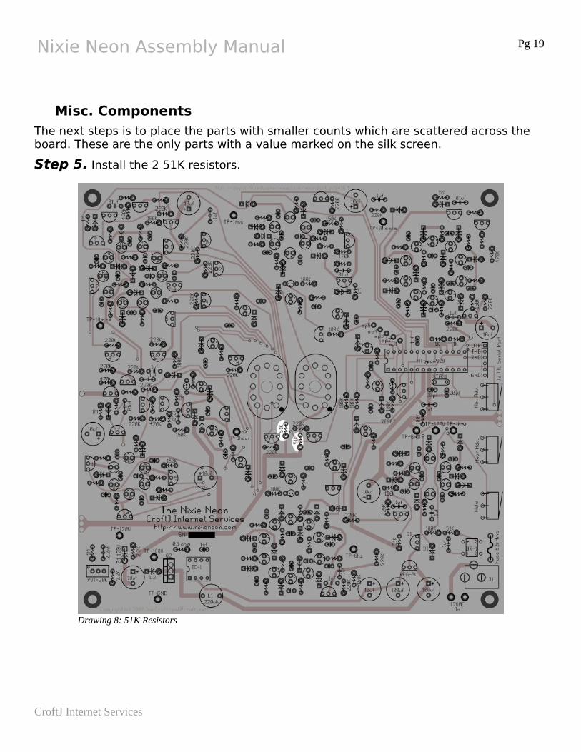
Misc. Components
The next steps is to place the parts with smaller counts which are scattered across the board. These are the only parts with a value marked on the silk screen.
Step 5. Install the 2 51K resistors.
CroftJ Internet Services
Drawing 8: 51K Resistors
Nixie Neon Assembly Manual Pg 20
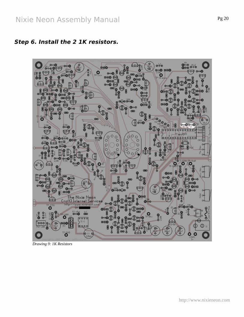
Step 6. Install the 2 1K resistors.
http://www.nixieneon.com
Drawing 9: 1K Resistors
Nixie Neon Assembly Manual Pg 21
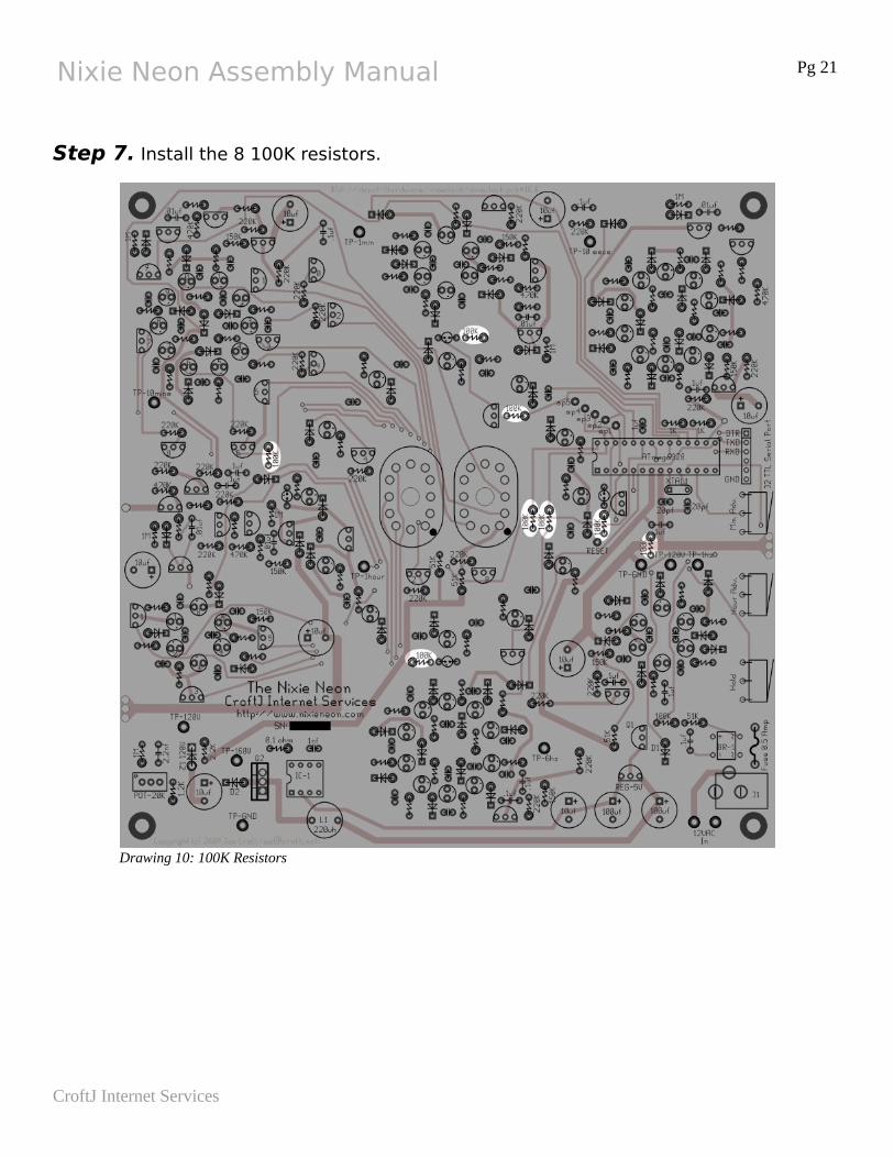
Step 7. Install the 8 100K resistors.
CroftJ Internet Services
Drawing 10: 100K Resistors
Nixie Neon Assembly Manual Pg 22
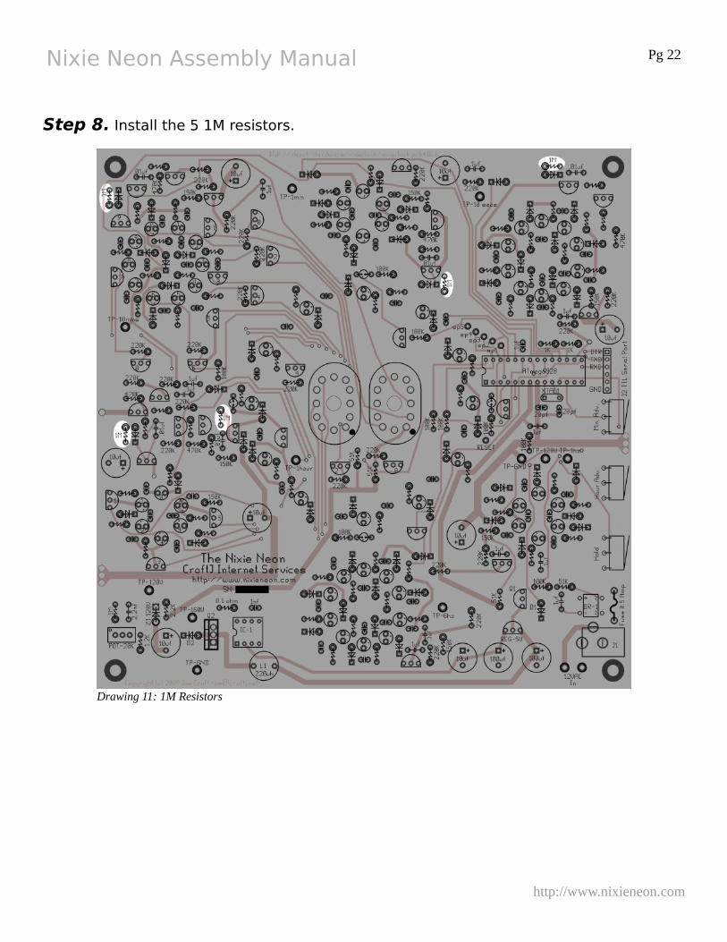
Step 8. Install the 5 1M resistors.
http://www.nixieneon.com
Drawing 11: 1M Resistors
Nixie Neon Assembly Manual Pg 23
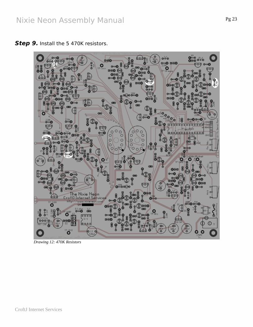
Step 9. Install the 5 470K resistors.
CroftJ Internet Services
Drawing 12: 470K Resistors
Nixie Neon Assembly Manual Pg 24
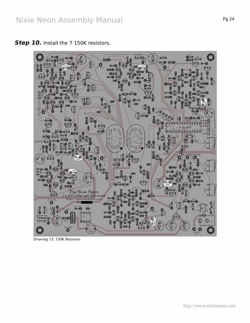
Step 10. Install the 7 150K resistors.
http://www.nixieneon.com
Drawing 13: 150K Resistors
Nixie Neon Assembly Manual Pg 25
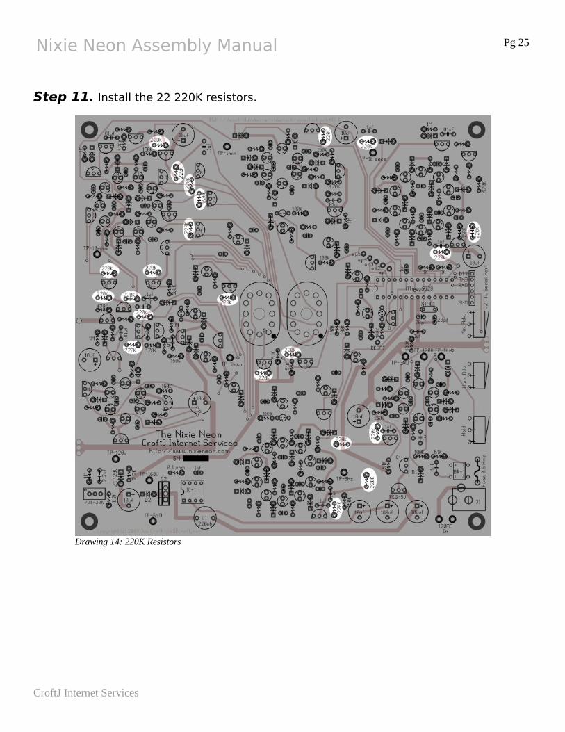
Step 11. Install the 22 220K resistors.
CroftJ Internet Services
Drawing 14: 220K Resistors
Nixie Neon Assembly Manual Pg 26
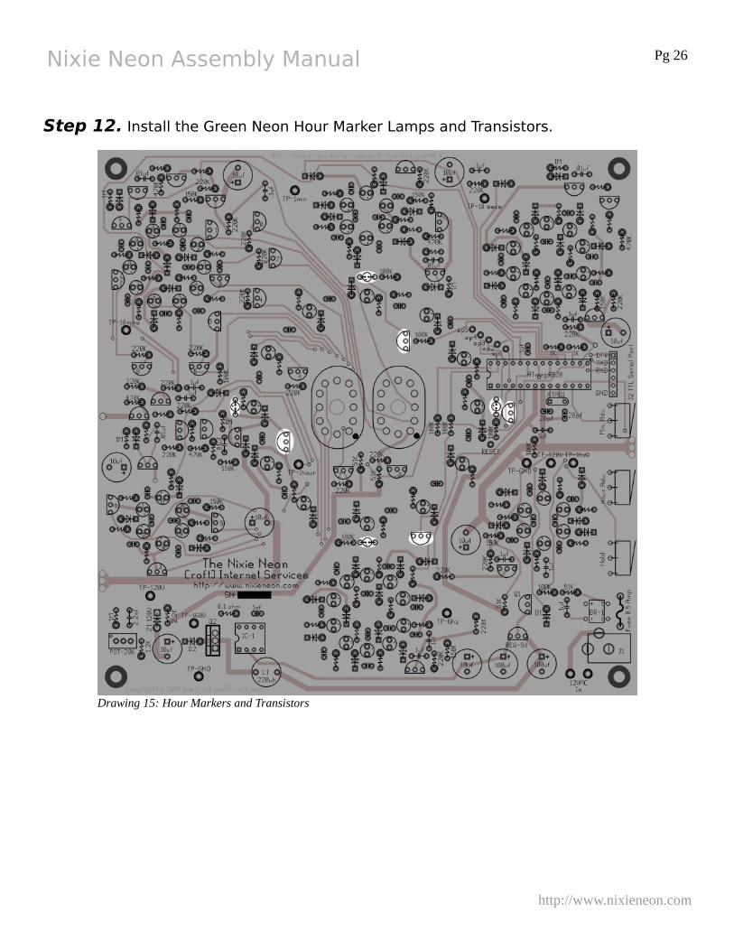
Step 12. Install the Green Neon Hour Marker Lamps and Transistors.
http://www.nixieneon.com
Drawing 15: Hour Markers and Transistors
Nixie Neon Assembly Manual Pg 27
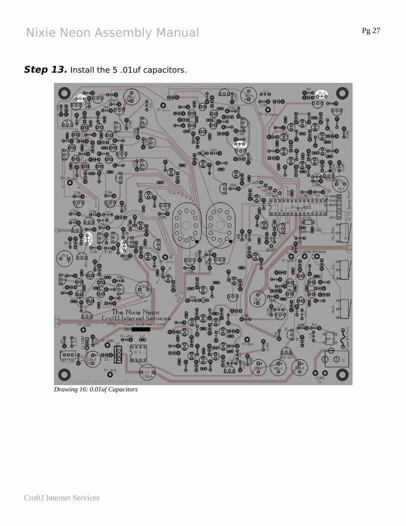
Step 13. Install the 5 .01uf capacitors.
CroftJ Internet Services
Drawing 16: 0.01uf Capacitors
Nixie Neon Assembly Manual Pg 28
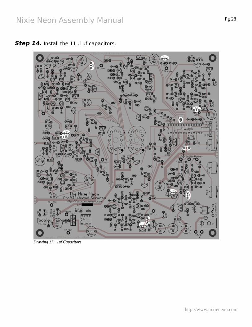
Step 14. Install the 11 .1uf capacitors.
http://www.nixieneon.com
Drawing 17: .1uf Capacitors
Nixie Neon Assembly Manual Pg 29
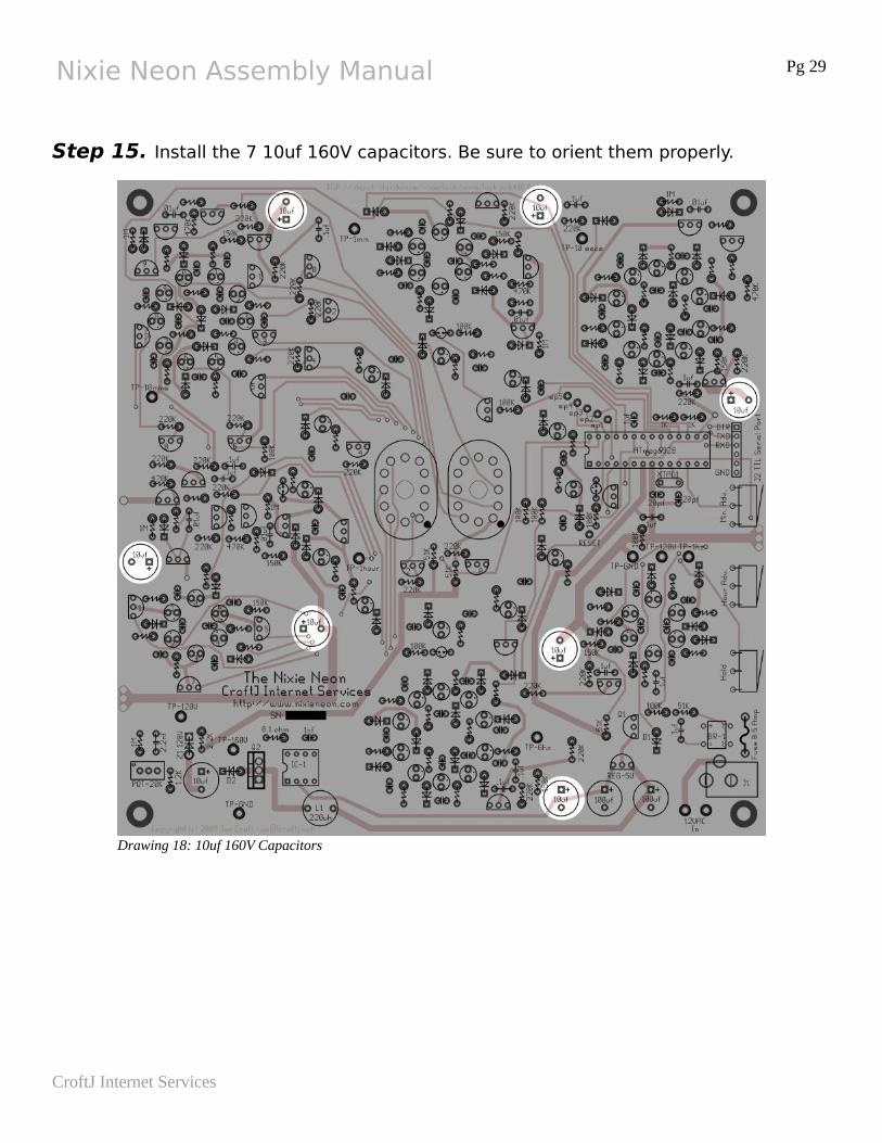
Step 15. Install the 7 10uf 160V capacitors. Be sure to orient them properly.
CroftJ Internet Services
Drawing 18: 10uf 160V Capacitors
Nixie Neon Assembly Manual Pg 30
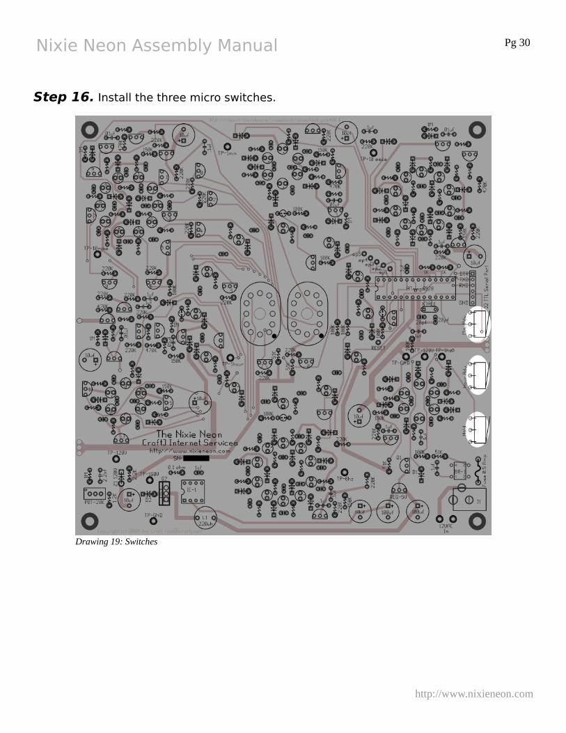
Step 16. Install the three micro switches.
http://www.nixieneon.com
Drawing 19: Switches
Nixie Neon Assembly Manual Pg 31
Ring Counters
The follow steps describe building the ring counters themselves. Build one ring at a time starting with the bottom center ring counter working your way around the board counter clockwise. You need to test each ring before moving the the next.
The order will be, 60hz Countdown, 6 hz Countdown, 1 Second Countdown, 10 Second Countdown, 1 Minute Countdown, 10 Minute Countdown, 1 Hour Countdown.
Begin assembling a ring by counting out the components required for the ring. Bend the leads of the diodes and resistors so they are close to the body as practical. Once the parts for the rings are counted and the leads bent, install the diodes, followed by the resistors, then the capacitors followed by the transistors. Be sure to orient the diodes and transistors correctly.
After the transistors, only the neon lamps are left. Each lamp should be installed individually on the board and soldering it. Once all of the lamps are in, check to make sure they are all straight. Small changes can be made from side to side by melting the solder on one leed or the other and gently pushing the lamp.
Be sure to test each ring before you move on to the next! These rings will sequence without the processor. The Rings past the 1 Second ring will have to be tested by connecting a wire from the TP-1Sec test point to the appropriate input test point of the ring. To test a ring, apply power to the clock and verify that one or more lamps light up. The bulbs should sequence from one to the next. Keep in mind that the rings alternate between sequencing clockwise and counterclockwise, just as if the rings were geers. The 60hz countdown rind sequences the bulbs clockwise.
Unplug the adapter and move to the next stage until all of the stages are complete.
Circuit Changes!
Because of the change to the high voltage supply, the 120V supply should be checked after each ring is completed and re-adjusted to ensure that it in the ball park of 125 volts.
In most cases, as long as the 120V supply is kept at about 125 volts, all of the rings should behave correctly.
If the rings still cause problems, raise and lower the 120V supply level to see if this helps the rings behave as you expect. Experience has shown that when the 120V supply is set to high, the 2nd ring (6Hz) will mis-fire with multiple bulbs turned on at the same time. If the voltage needs to be set that high to make the other rings behave, the 150K resistor on the 2nd ring can be raised to help keep it firing correctly.
CroftJ Internet Services

Nixie Neon Assembly Manual Pg 32
http://www.nixieneon.com
Nixie Neon Assembly Manual Pg 33
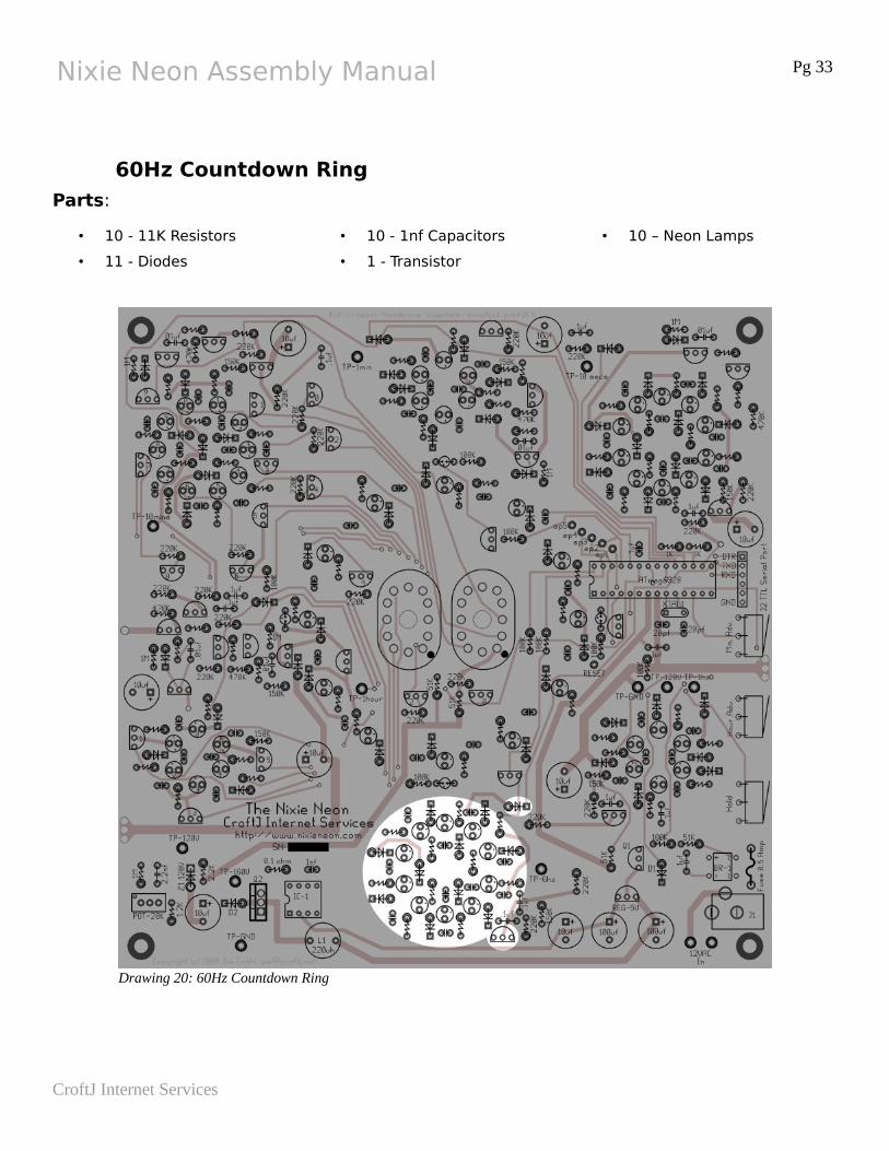
60Hz Countdown Ring
Parts:
• 10 - 11K Resistors
• 11 - Diodes
• 10 - 1nf Capacitors
• 1 - Transistor
• 10 – Neon Lamps
CroftJ Internet Services
Drawing 20: 60Hz Countdown Ring
Nixie Neon Assembly Manual Pg 34
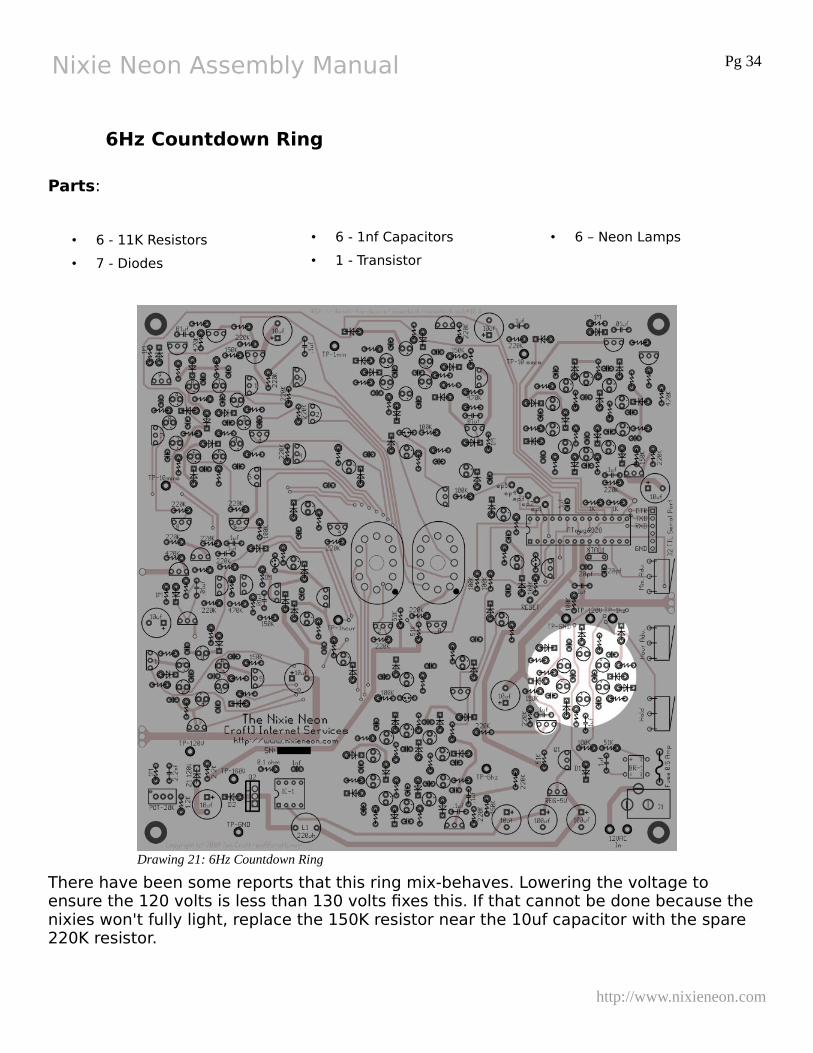
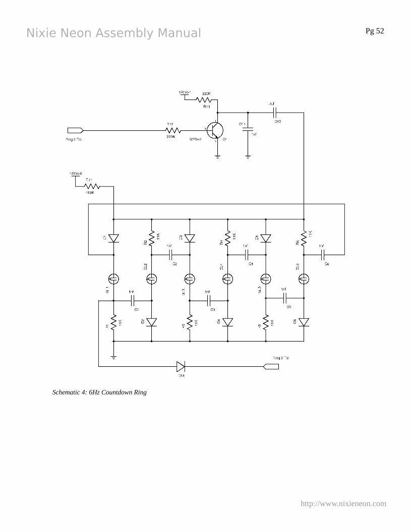
6Hz Countdown Ring
Parts:
• 6 - 11K Resistors
• 7 - Diodes
• 6 - 1nf Capacitors
• 1 - Transistor
• 6 – Neon Lamps
There have been some reports that this ring mix-behaves. Lowering the voltage to ensure the 120 volts is less than 130 volts fixes this. If that cannot be done because the nixies won't fully light, replace the 150K resistor near the 10uf capacitor with the spare 220K resistor.
http://www.nixieneon.com
Drawing 21: 6Hz Countdown Ring
Nixie Neon Assembly Manual Pg 35
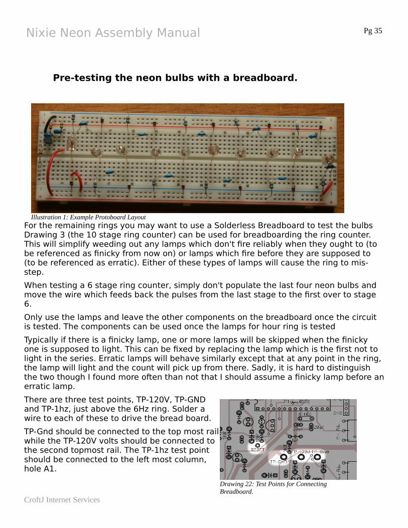
Pre-testing the neon bulbs with a breadboard.
For the remaining rings you may want to use a Solderless Breadboard to test the bulbs Drawing 3 (the 10 stage ring counter) can be used for breadboarding the ring counter. This will simplify weeding out any lamps which don't fire reliably when they ought to (to be referenced as finicky from now on) or lamps which fire before they are supposed to (to be referenced as erratic). Either of these types of lamps will cause the ring to mis-step.
When testing a 6 stage ring counter, simply don't populate the last four neon bulbs and move the wire which feeds back the pulses from the last stage to the first over to stage 6.
Only use the lamps and leave the other components on the breadboard once the circuit is tested. The components can be used once the lamps for hour ring is tested
Typically if there is a finicky lamp, one or more lamps will be skipped when the finicky one is supposed to light. This can be fixed by replacing the lamp which is the first not to light in the series. Erratic lamps will behave similarly except that at any point in the ring, the lamp will light and the count will pick up from there. Sadly, it is hard to distinguish the two though I found more often than not that I should assume a finicky lamp before anerratic lamp.
There are three test points, TP-120V, TP-GNDand TP-1hz, just above the 6Hz ring. Solder awire to each of these to drive the bread board.
TP-Gnd should be connected to the top most railwhile the TP-120V volts should be connected tothe second topmost rail. The TP-1hz test pointshould be connected to the left most column,hole A1.
CroftJ Internet Services
Illustration 1: Example Protoboard Layout
Drawing 22: Test Points for Connecting Breadboard.

Nixie Neon Assembly Manual Pg 36
http://www.nixieneon.com
Nixie Neon Assembly Manual Pg 37
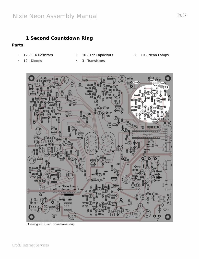
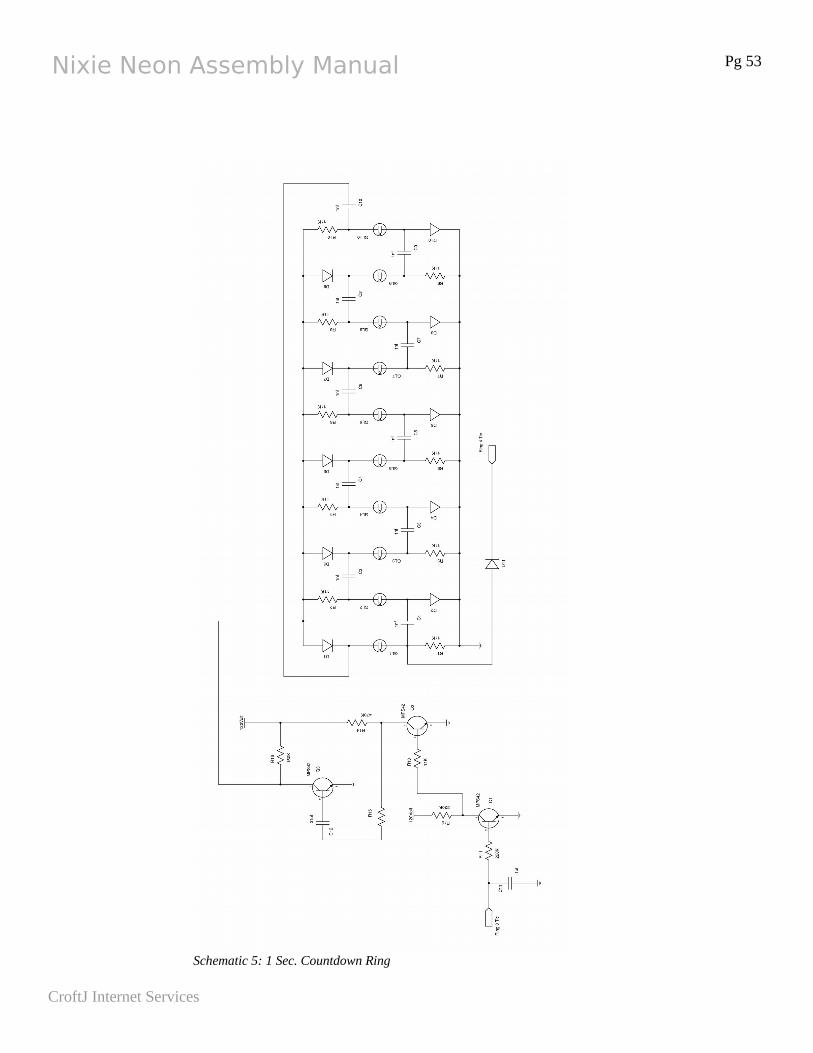
1 Second Countdown Ring
Parts:
• 12 - 11K Resistors
• 12 - Diodes
• 10 - 1nf Capacitors
• 3 - Transistors
• 10 – Neon Lamps
CroftJ Internet Services
Drawing 23: 1 Sec. Countdown Ring
Nixie Neon Assembly Manual Pg 38
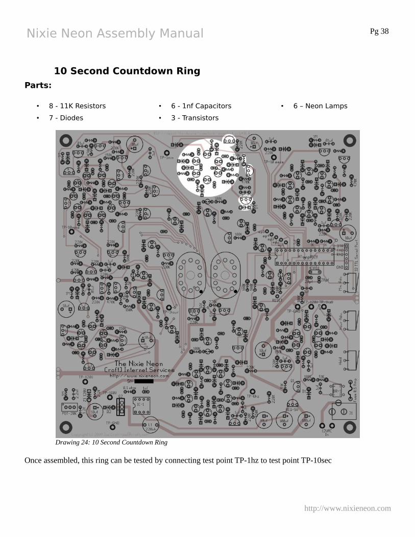
10 Second Countdown Ring
Parts:
• 8 - 11K Resistors
• 7 - Diodes
• 6 - 1nf Capacitors
• 3 - Transistors
• 6 – Neon Lamps
Once assembled, this ring can be tested by connecting test point TP-1hz to test point TP-10sec
http://www.nixieneon.com
Drawing 24: 10 Second Countdown Ring
Nixie Neon Assembly Manual Pg 39
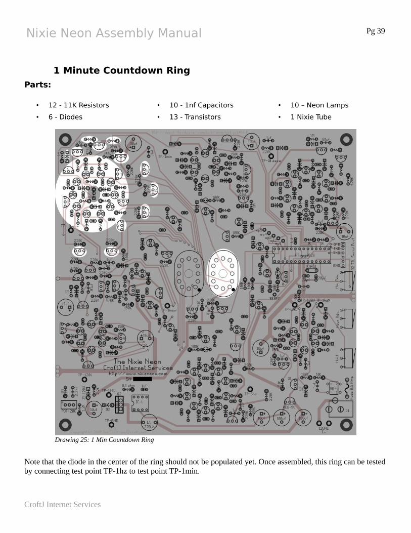
1 Minute Countdown Ring
Parts:
• 12 - 11K Resistors
• 6 - Diodes
• 10 - 1nf Capacitors
• 13 - Transistors
• 10 – Neon Lamps
• 1 Nixie Tube
Note that the diode in the center of the ring should not be populated yet. Once assembled, this ring can be testedby connecting test point TP-1hz to test point TP-1min.
CroftJ Internet Services
Drawing 25: 1 Min Countdown Ring
Nixie Neon Assembly Manual Pg 40
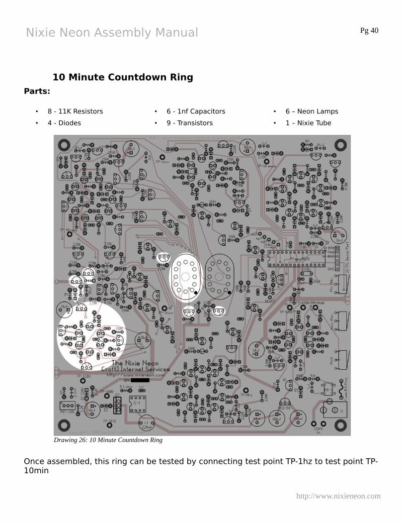
10 Minute Countdown Ring
Parts:
• 8 - 11K Resistors
• 4 - Diodes
• 6 - 1nf Capacitors
• 9 - Transistors
• 6 – Neon Lamps
• 1 – Nixie Tube
Once assembled, this ring can be tested by connecting test point TP-1hz to test point TP-10min
http://www.nixieneon.com
Drawing 26: 10 Minute Countdown Ring
Nixie Neon Assembly Manual Pg 41
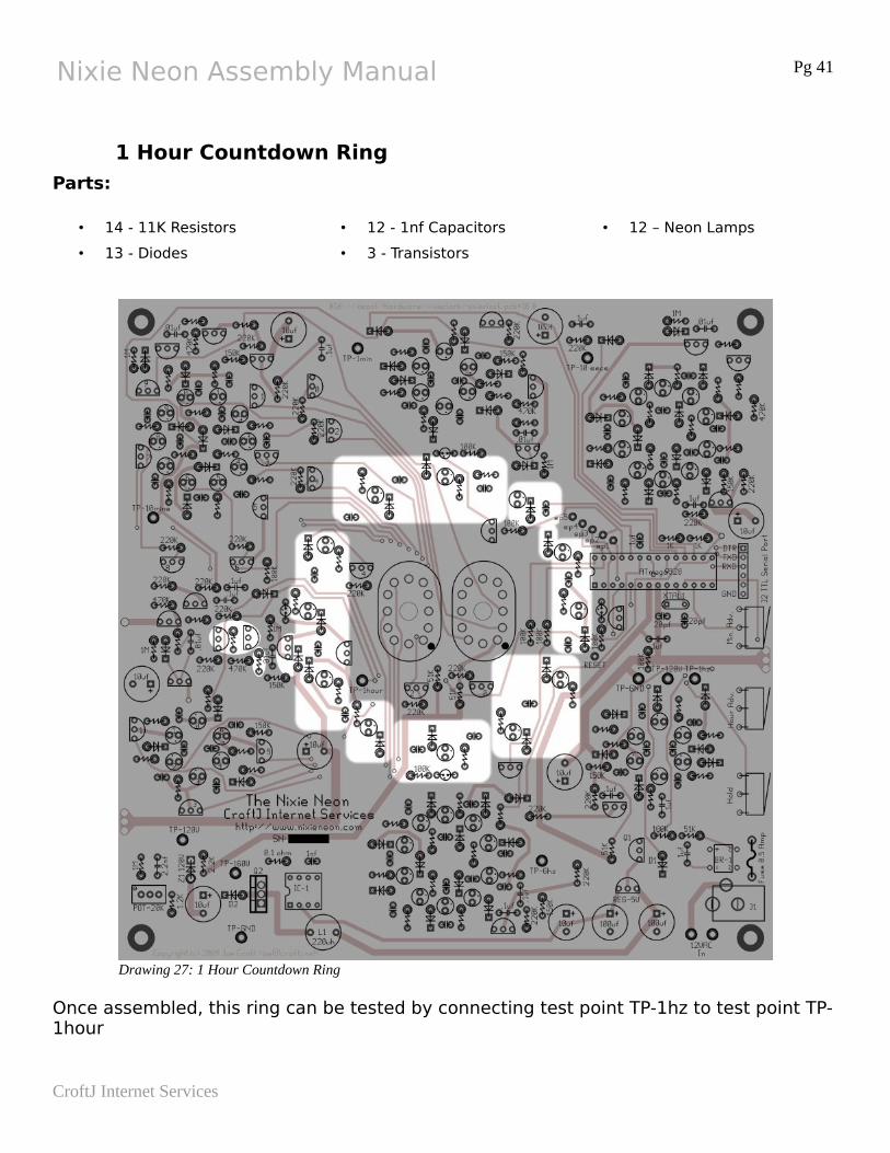
1 Hour Countdown Ring
Parts:
• 14 - 11K Resistors
• 13 - Diodes
• 12 - 1nf Capacitors
• 3 - Transistors
• 12 – Neon Lamps
Once assembled, this ring can be tested by connecting test point TP-1hz to test point TP-1hour
CroftJ Internet Services
Drawing 27: 1 Hour Countdown Ring

Nixie Neon Assembly Manual Pg 42
Inter-Ring Diodes
Parts:
• 3 diodes
http://www.nixieneon.com
Drawing 28: Inter-ring Diodes
Nixie Neon Assembly Manual Pg 43
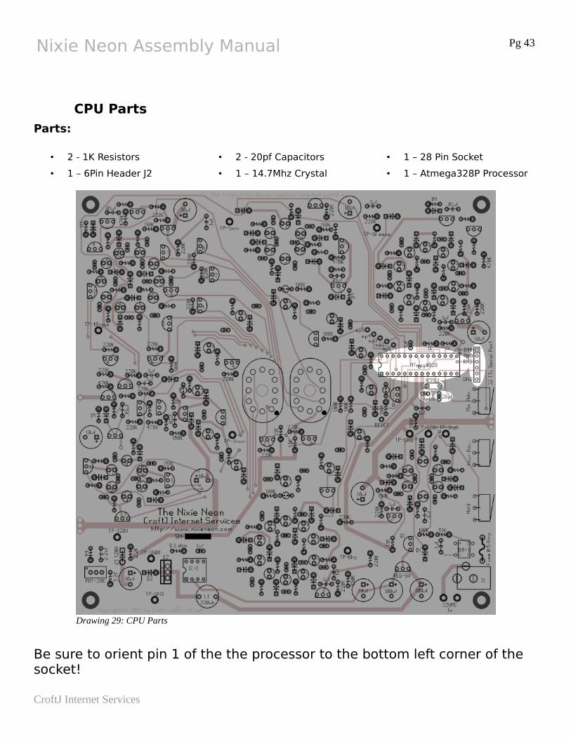
CPU Parts
Parts:
• 2 - 1K Resistors
• 1 – 6Pin Header J2
• 2 - 20pf Capacitors
• 1 – 14.7Mhz Crystal
• 1 – 28 Pin Socket
• 1 – Atmega328P Processor
Be sure to orient pin 1 of the the processor to the bottom left corner of the socket!
CroftJ Internet Services
Drawing 29: CPU Parts
Nixie Neon Assembly Manual Pg 44
Clock Operation
A Note of Caution!
Before you touching the clock, you should try to discharge yourself first. Ihaven't damaged a clock with a static zap, but I have made them display some
interesting times on their rings.
Reading the clock is fairly straight forward. The minutes are displayed on the two digits while the hours are displayed by the circle of 12 neon bulbs encircling the digits.
Yet Another Note
When power is applied to the clock, even after brief interruptions, the clock willreset itself to 1 o'clock.
Setting the Time
To set the clock, press and let go of either the Min. Adv switch or the Hour Adv. switch. The clock will then reset itself to the time it has in it's memory. Once the clock has reset its time, Either the 12 and 6 o'clock markers will light or the 3 and 9 o'clock markers will light.
At this point the minutes can be advanced by pressing and holding the Min. Adv. switch and the hours can be advance by pressing and holding the Hour Adv. switch. You can go back and forth between the two switches until the correct time is reached.
Pressing and releasing the the Hold button will start the clock.
Diagnostic Modes
Currently there is only one diagnostic mode. It will allow you to sequence a the ring counters at an accelerated rate using the processor.
Pressing both the Hold switch and the Hour Adv. switch simultaneously will enter this mode and the 12 o'clock hour marker will light. Initially the 60Hz countdown ring will be run. Pressing and releasing the Min. Adv Switch will step the sequencing to the next ring until finally the Hour Countdown Ring is reached. After this the clock will resume
http://www.nixieneon.com
Nixie Neon Assembly Manual Pg 45
operation from the time it has in it memory the next time the Min. Adv. switch is pressed and released.
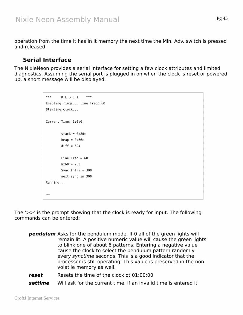
Serial Interface
The NixieNeon provides a serial interface for setting a few clock attributes and limited diagnostics. Assuming the serial port is plugged in on when the clock is reset or powered up, a short message will be displayed.
*** R E S E T ***
Enabling rings... line freq: 60
Starting clock...
Current Time: 1:0:0
stack = 0x8dc
heap = 0x66c
diff = 624
Line Freq = 60
hz60 = 253
Sync Intrv = 300
next sync in 300
Running...
>>
The '>>' is the prompt showing that the clock is ready for input. The following commands can be entered:
pendulum Asks for the pendulum mode. If 0 all of the green lights will remain lit. A positive numeric value will cause the green lightsto blink one of about 6 patterns. Entering a negative value cause the clock to select the pendulum pattern randomly every synctime seconds. This is a good indicator that the processor is still operating. This value is preserved in the non-volatile memory as well.
reset Resets the time of the clock ot 01:00:00
settime Will ask for the current time. If an invalid time is entered it
CroftJ Internet Services
Nixie Neon Assembly Manual Pg 46
will discard the time entered and leave the time unchanged.
start Starts the clock running
step Starts with the first ring running it at an accelerated rate. It then asks for the next ring to run. Any non-numeric entry will start the clock running normally.
stop Stops the clock from running, this does not stop the internal time keeping of the processor.
synctime Asks for the time in seconds to wait between resynchronizing the displayed time to the time the processor has. Setting this value to 0 will disable this function. This value is saved in the non-volatile memory and survives the loss of power.
status This command shows the current time status of the clock.
http://www.nixieneon.com
Nixie Neon Assembly Manual Pg 47
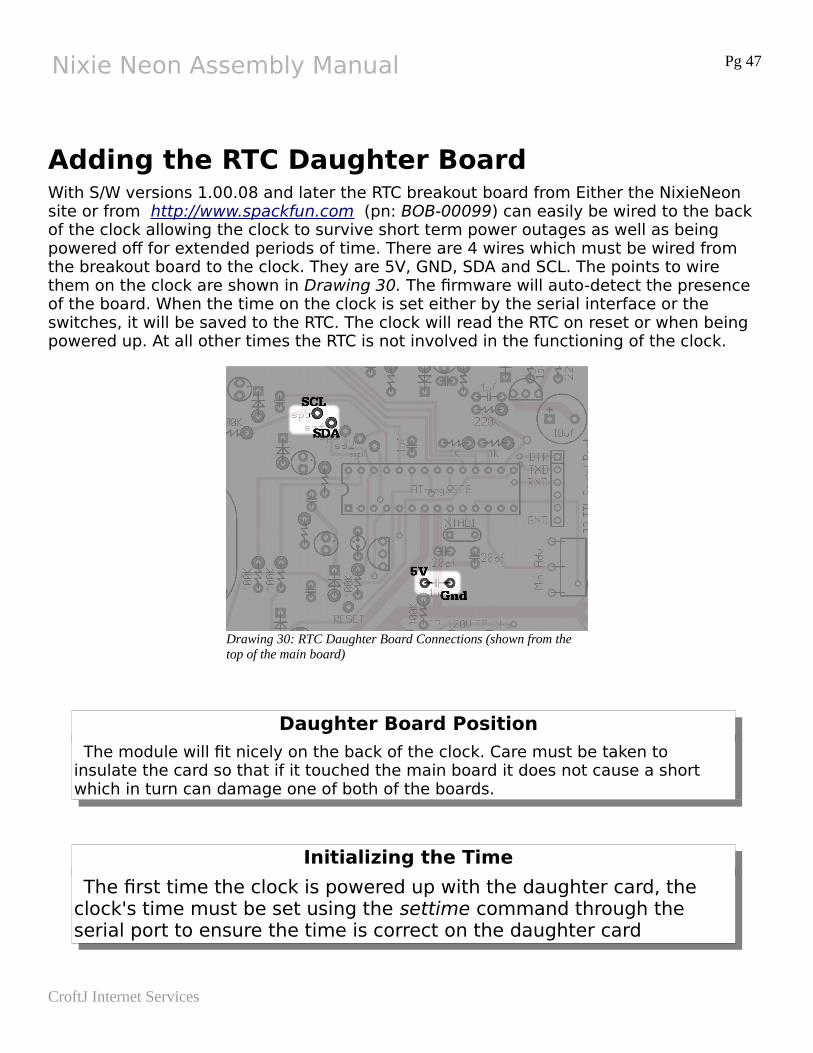
Adding the RTC Daughter BoardWith S/W versions 1.00.08 and later the RTC breakout board from Either the NixieNeon site or from http://www.spackfun.com (pn: BOB-00099) can easily be wired to the back of the clock allowing the clock to survive short term power outages as well as being powered off for extended periods of time. There are 4 wires which must be wired from the breakout board to the clock. They are 5V, GND, SDA and SCL. The points to wire them on the clock are shown in Drawing 30. The firmware will auto-detect the presence of the board. When the time on the clock is set either by the serial interface or the switches, it will be saved to the RTC. The clock will read the RTC on reset or when being powered up. At all other times the RTC is not involved in the functioning of the clock.
Daughter Board Position
The module will fit nicely on the back of the clock. Care must be taken to insulate the card so that if it touched the main board it does not cause a short which in turn can damage one of both of the boards.
Initializing the Time
The first time the clock is powered up with the daughter card, the clock's time must be set using the settime command through the serial port to ensure the time is correct on the daughter card
CroftJ Internet Services
Drawing 30: RTC Daughter Board Connections (shown from the top of the main board)
Nixie Neon Assembly Manual Pg 48
Software Updates On occasions, updates will be made to the software to fix bugs and add features. These updates with instructions on how to apply them can be found on the NixieNeon web site http://www.nixieneon.com.
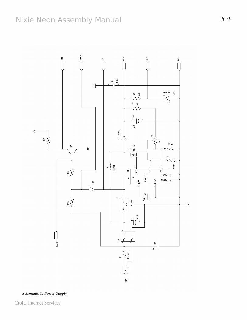
Clock SchematicsThese are the full schematics of the clock. Not that the component designators on each schematic are local to the schematic and are not clock wide. In other words, Q1 is uniqueon any given schematic, but multiple schematics can have a Q1.
These schematics currently are slightly different than reality. Most of the inconsistencies are small and lay in the low voltage power supply. Case in point is the diode is not a 1n22but a 1S422. There may be other small errors as well. The board is the the real device and the silkscreen is accurate.
http://www.nixieneon.com
Nixie Neon Assembly Manual Pg 49
CroftJ Internet Services
Schematic 1: Power Supply
Nixie Neon Assembly Manual Pg 50
http://www.nixieneon.com
Schematic 2: Processor and Associated Parts
Nixie Neon Assembly Manual Pg 51
CroftJ Internet Services
Schematic 3: 60Hz Countdown Ring
Nixie Neon Assembly Manual Pg 52
http://www.nixieneon.com
Schematic 4: 6Hz Countdown Ring
Nixie Neon Assembly Manual Pg 53
CroftJ Internet Services
Schematic 5: 1 Sec. Countdown Ring
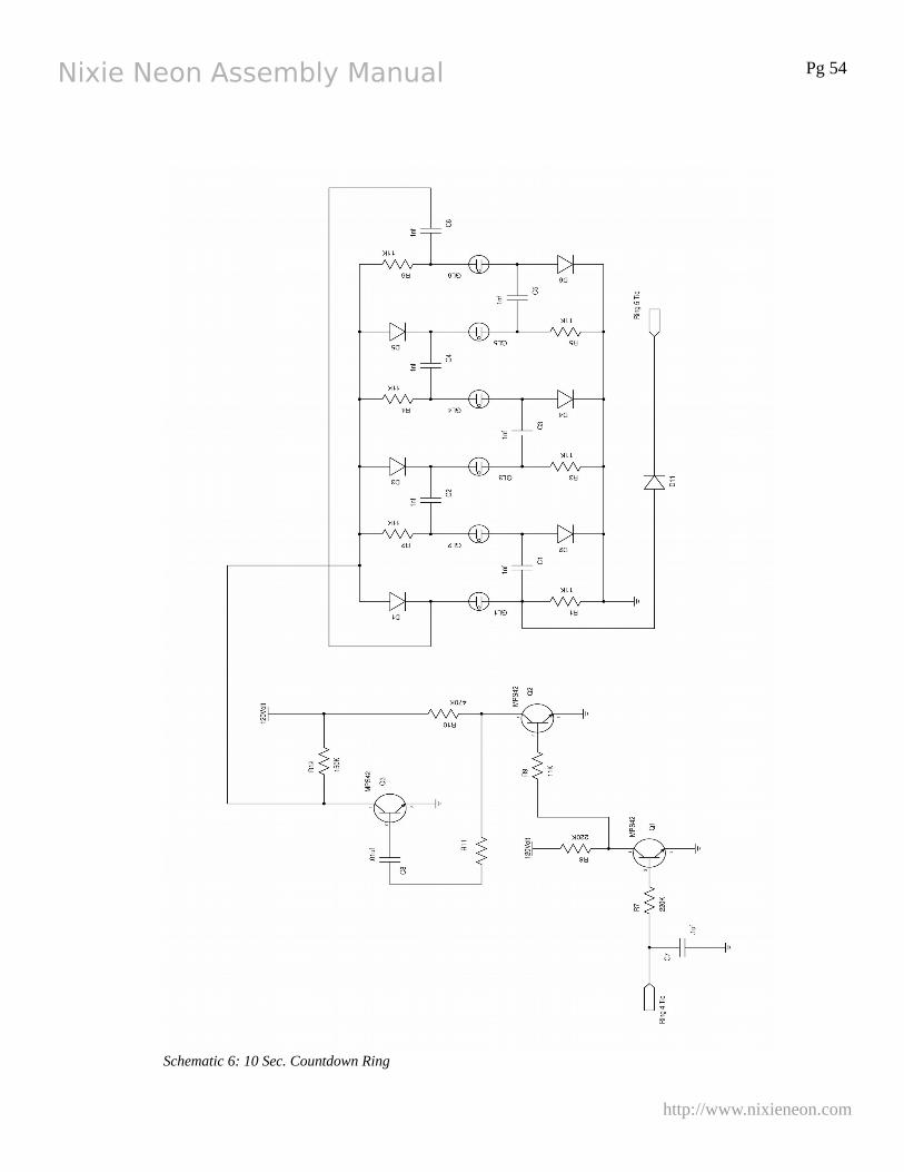
Nixie Neon Assembly Manual Pg 54
http://www.nixieneon.com
Schematic 6: 10 Sec. Countdown Ring
Nixie Neon Assembly Manual Pg 55
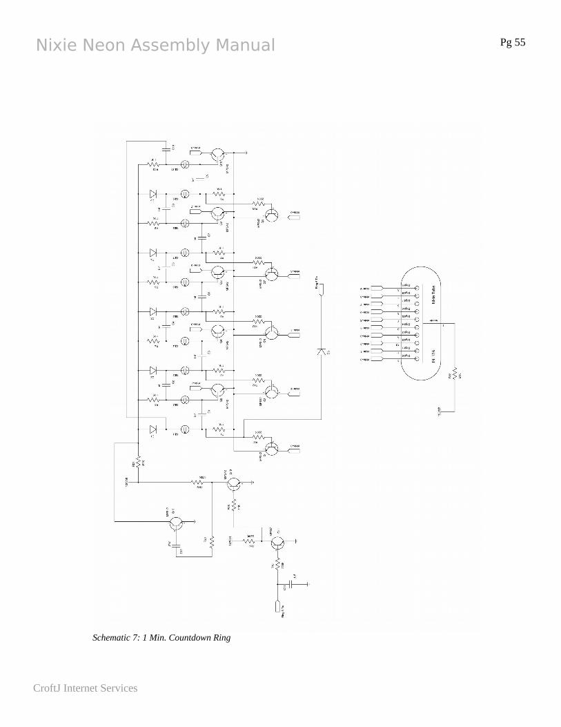
CroftJ Internet Services
Schematic 7: 1 Min. Countdown Ring
Nixie Neon Assembly Manual Pg 56
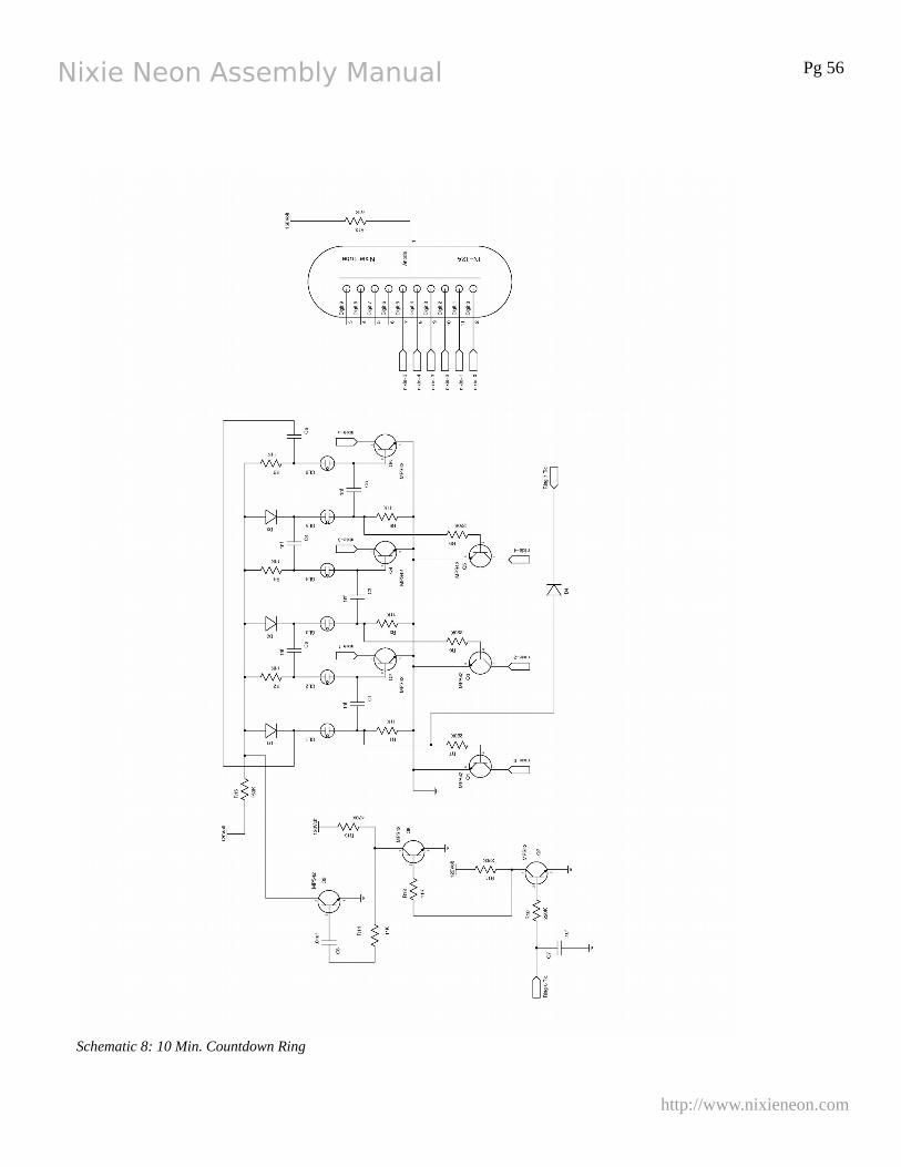
http://www.nixieneon.com
Schematic 8: 10 Min. Countdown Ring
Nixie Neon Assembly Manual Pg 57
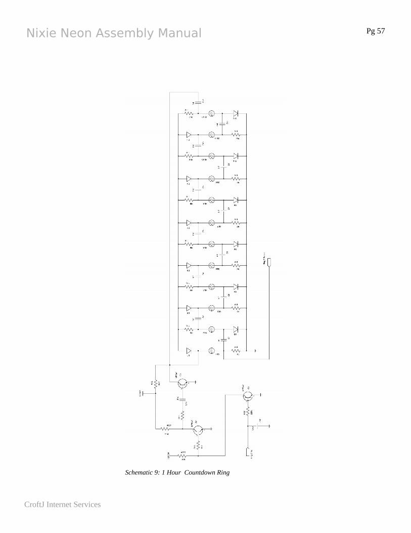
CroftJ Internet Services
Schematic 9: 1 Hour Countdown Ring
Nixie Neon Assembly Manual Pg 58
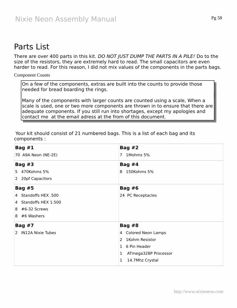
Parts ListThere are over 400 parts in this kit. DO NOT JUST DUMP THE PARTS IN A PILE! Do to the size of the resistors, they are extremely hard to read. The small capacitors are even harder to read. For this reason, I did not mix values of the components in the parts bags.
Component Counts
On a few of the components, extras are built into the counts to provide those needed for bread boarding the rings.
Many of the components with larger counts are counted using a scale, When a scale is used, one or two more components are thrown in to ensure that there areadequate components. If you still run into shortages, except my apologies and contact me at the email adress at the from of this document.
Your kit should consist of 21 numbered bags. This is a list of each bag and its components :
Bag #1
70 A9A Neon (NE-2E)
Bag #2
7 1Mohms 5%
Bag #3
5 470Kohms 5%
2 20pf Capacitors
Bag #4
8 150Kohms 5%
Bag #5
4 Standoffs HEX .500
4 Standoffs HEX 1.500
8 #6-32 Screws
8 #6 Washers
Bag #6
24 PC Receptacles
Bag #7
2 IN12A Nixie Tubes
Bag #8
4 Colored Neon Lamps
2 1Kohm Resistor
1 6 Pin Header
1 ATmega328P Processor
1 14.7Mhz Crystal
http://www.nixieneon.com
Nixie Neon Assembly Manual Pg 59
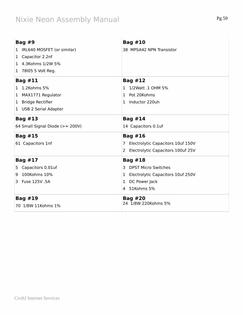
Bag #9
1 IRL640 MOSFET (or similar)
1 Capacitor 2.2nf
1 4.3Kohms 1/2W 5%
1 78l05 5 Volt Reg.
Bag #10
38 MPSA42 NPN Transistor
Bag #11
1 1.2Kohms 5%
1 MAX1771 Regulator
1 Bridge Rectifier
1 USB 2 Serial Adapter
Bag #12
1 1/2Watt .1 OHM 5%
1 Pot 20Kohms
1 Inductor 220uh
Bag #13
64 Small Signal Diode (>= 200V)
Bag #14
14 Capacitors 0.1uf
Bag #15
61 Capacitors 1nf
Bag #16
7 Electrolytic Capacitors 10uf 150V
2 Electrolytic Capacitors 100uf 25V
Bag #17
5 Capacitors 0.01uf
9 100Kohms 10%
3 Fuse 125V .5A
Bag #18
3 DPST Micro Switches
1 Electrolytic Capacitors 10uf 250V
1 DC Power Jack
4 51Kohms 5%
Bag #19
70 1/8W 11Kohms 1%
Bag #2024 1/8W 220Kohms 5%
CroftJ Internet Services