nibe™ f1345 ground source heat pump - · pdf filedesignations in component locations...
TRANSCRIPT

2 stage heat pump with rock, earth, lake or ground water as heat source.
• Lessthan3kgrefrigerantpercoolingsection/installation.Thismeansnoinspectionrequirement.
• Thetwoscrollcompressorscansupplyupto65°Ctotheheatingsystem.
• Doublecompressorsgivebetterpowercontrol,longeroper-atingintervals,lesswearandgreateroperationalsecurity.
• Displayunitwitheasy-to-readcolourscreen.
• –SeestatusandmakesettingsviaSMSwiththeSMS40accessory.–Controltheheatpumpexternally,withforexampleBMS,
viatheaccessoryMODBUS40.
• Theheatpumpisavailableinthefollowingsizes:24,30,40and60kW.
• Upto540kWwith9xF1345inthesamesystem.
• Softstartrelaysandloadmonitorfactoryinstalled.
• Internallyinstalledlowenergycirculationpumps(notbrinepumpfor40or60kW).
• PreparedforpoolheatingwithPOOL40accessory.
• PreparedforcontrolofuptofourheatingsystemswithECS40/ECS41accessory.
• CoefficientOfPerformance(COP)upto4.51at0/35C accordingtoEN14511.
• Separatecoolingmodulesforcompressorsandbrinepumpsgivereliableserviceandlowernoiselevels.
• Easytoremovethecoolingmodules.
NIBE™F1345GROUNDSOURCEHEATPUMP
NIBE F1345NIBE™F1345isaheatpumpforheatinglargebuildings,suchasapartmentbuildings,churchesandindustrialpremises.F1345isaflexibleproductwithadvancedcontrolequipmentandcanbeadaptedtoseveralsystemsolutions.Theground,bedrockorlakescanbeusedastheheatsource.Groundwatercanalsobeusedasaheatsource,butthisrequiresanintermediateheatexchanger.Anotherareaofusecouldalsobeventilationrecoveryinmulti-occupancy buildings. F1345 can control up to four differentclimate systems (requires accessory), for example a lower flowtemperatureintheunderfloorheatingloopsthanintheradiators.F1345isalsopreparedforcontrolofanexternaladditionalheater.Athotwaterproductionthiscanbeprioritised,selectablewithoneormorecompressors.Thispermitssimultaneousproductionofheatandhotwater.

2NIBEF1345
installation method
Theterm“groundsource”coversfourdifferentheatsources:rock,surfacesoil,groundwaterandlake.
Ground waterA viable energy source for any building where ground water is easily accessible.
Ground water can also be utilised as a heat source since ithasa temperatureofbetween4and12°Call-year round.Theheatpumpcollectsstoredsolarenergyfromthegroundwater.Normally, there is one well for drawing up water and one forreturningit.
Lake collectorCost-effective installation for lakeside homes.
Ifyourhomeisbuiltbesideawatersourcesuchasalake,heatfromthelakewatercanbeextractedusingasurfacesoilcollectoranchoredtothebottomofthelake.
Rock - using a ground probeIdeal for refurbishment or adaptation from a fossil fuel heating system.
In the lower subsoil of the so-called “near-surface geothermallayer” lies a heat source with an almost constant temperaturethatcanbeutilisedallyearround.Theheatpumpcollectsstoredsolarenergyfromacollectorinaholedrilledintotherock.Thedepthoftheholecanvarybetween90–200metres,dependingon thesizeofheatpumpselected.This typeof systemcanbeused for all possible building types, large or small, public orprivate.Itrequireslittlespaceandthegroundprobecanbedrilledinthesmallestofgardens.
Surface soil - using a surface collectorCost-effective energy collection.
During the summer, solar heat is stored in the soil. This iseither directly absorbed as insulation or as heat from rain andthe air from the near-surface layer of the soil. The heat pumpcollectsthisstoredsolarenergyfromaburiedcollector.That is,a hose filled with anti-freeze, and buried at a depth of about80 – 100 cm, the length of the hose varies between 250 and400 metres, depending on the size of heat pump selected.Using this energy for heating is a cost effective method. Thehighestyieldcanbeobtainedfromsoilwithahighwatercontent.

F1345 is extremely efficient thanks to a highly effectivecompressor in well dimensioned refrigerant circuits. Internallyinstalledlowenergycirculationpumpsandflexhoses(notbrinepumpfor40or60kW).Thebrinerespectivelyheatingmediumcircuitsareconnectedfromtherearof theheatpump.Particlefiltersupplied.Theheatpumpcanbeconnectedtoanoptionallowtemperaturedistributionsystem.e.g.radiators,convectorsorunderfloorheating.F1345isequippedwithacontrolcomputerforoptimumandreliableoperation.AlargebacklitTFTdisplayshowsinformationaboutstatus,operatingtimeandalltemperaturesintheheatpumpaswellascertaininformationaboutanyslaveheatpumps,incolourusingiconsandtext.F1345isconstructedonarobustframewithdurablepanelsandeffectivesoundproofingforthebestpossiblecomfort.Allpanelsareeasytoremoveforeasyaccesswheninstallingandforservicing.
NIBEF13453
Evaporator
Heatingmediumsupply
Heatingmediumsupply
Brinein
Brinein
Brineout
Brineout
Heatingmediumreturn
Heatingmediumreturn
Condenser
*Thebrinepump(1x)for40or60kWissuppliedandinstalledexternally
outsidetheheatpump.
SleevepipeBrinetoheatpump
Groundwaterlevel
Activeborehole(watercolumnin
rock)
Brinefromheatpump
40kW24-30kW 60kW
Circulationpump
Circulationpump
ExpansionvalveCoolingmoduleEP14
CoolingmoduleEP15
Compressor
Compressor
Brinepump*
Brinepump*
F1345 consists of two heat pump modules (cooling module),circulationpumpsandcontrolsystemwithpossibilityofadditionalheat. F1345 is connected to the brine and heating mediumcircuits.
Intheheatpumpevaporator,thebrine(watermixedwithanti-freeze,glycolor ethanol) releases its energy to the refrigerant,whichisvaporisedinordertobecompressedinthecompressor.Therefrigerant,ofwhichthetemperaturehasnowbeenraised,ispassed to thecondenserwhere itgivesoff itsenergy to theheatingmediumcircuit and, if necessary, to anydockedwaterheater.Ifthereisagreaterneedforheating/hotwaterthanthecompressorscanprovide it ispossible istoconnectanexternalimmersionheater.
how does F1345 work?
Principle of operation

4NIBEF1345
F1345shouldbetransportedandstoredverticallyinadryplace.
Whenbeingmovedintoabuilding,F1345maybeleantback45°.NOTE!Theheatpumpistopheavy.
If thecoolingmodulesarepulledoutand transportedupright,F1345canbetransportedonitsback.
The side panels can be removed for easier installation in thebuilding.
R
0
+ 20-2
1
R
0
H M flo w4 9 (5 0 ) °CH o t w a te r 5 1 °C
+20
-2
1 R0
HM
flow4
9 (5
0) °C
Hot
wate
r51 °C
R0
• Position F1345 on a firm base that can take the weight,preferablyonaconcretefloororfoundation.Usetheheatpump’sadjustablefeettoobtainastableset-up.
• Install with its back to an outside wall, ideally in a roomwhere noise does not matter, in order to eliminate noiseproblems. If this is notpossible, avoidplacing it against awallbehindabedroomorotherroomwherenoisemaybeaproblem.
• Wherevertheunitislocated,wallstosoundsensitiveroomsshouldbefittedwithsoundinsulation.
• Route pipes so they are not fixed to an internal wall thatbacksontoabedroomorlivingroom.
(50) (50)
800
NOTE!Ensurethattheheatpumpcannotfalloverduringtransport.
LE
K
*Anormalinstallationneeds300-400mm(anyside)forconnectionequipment,i.e.levelvessel,valvesandelectricalequipment.
**
Tosimplifytransportandservice,theheatpumpcanbeseparatedbypullingthecoolingmoduleoutfromthecabinet.
Seetheinstallermanualforcomprehensiveinstructionsabouttheseparation.
Leave a space of 800 mm in front of the heat pump.Approximately 50 mm free space is required on each sidein order to open the side hatches. The hatches do not needto be opened during service, all service on F1345 can becarried out from the front. There must be at least 300mm offree space above the heat pump. Leave space between theheat pump and wall behind (and any routing of supply cablesandpipes) to reduce the riskof reproductionof any vibration.
good to know about nibe™ F1345
Transport and storage Assembly
Drawing out the cooling module
Installation area

NIBEF13455
1775
600
560 440
735
1555
1715
80 145 145 145
450620
820
85
25-
50
good to know about nibe™ F1345
Dimensions

6NIBEF1345
LEK
LE
K
LEKLEK
AA2
AA26
EP14-XL1
EP15-XL1
AA3
EP14-XL2
EP14-PF2
EP15-PF2
EP15-XL2
BT10 BT10
EP2 EP2
EP1 EP1
GQ10 GQ10
BT3 BT3
GP2
GP1 GP1
QM1
QM2
QM1
QM2
BT12 BT12
AA100 AA100
EP15-FB1
EP14-FB1
SF1
AA4
X7
UB3
EP15-AA10
EP14-AA10
X1
AA7
EP14-XL7
EP15-XL7
UB1
FC1
EP14-XL6
EP15-XL6
PF3
PF1
UB2
EP15
EP14
FC1
BT11 BT11
UB1UB2UB3X2 X3 X4 X5 X6
CoolingsectionF134524and30kW CoolingsectionF134540and60kW
good to know about nibe™ F1345
Equipment

NIBEF13457
Pipe connections
XL1 Connection,heatingmediumflow
XL2 Connection,heatingmediumreturn
XL6 Connection,brinein
XL7 Connection,brineout
HVAC components
EP14 Coolingmodule
EP15 Coolingmodule
GP1 Circulationpump
GP2 Brinepump
QM1 Drainage,climatesystem
QM2 Draining,brineside
Cooling components
EP1 Evaporator
EP2 Condenser
GQ10 Compressor
Sensors etc.
BT1 Temperaturesensor,outdoor
BT10 Temperaturesensor,brinein
BT11 Temperaturesensor,brineout
BT12 Temperaturesensor,condensersupplyline
Electrical components
AA2 Basecard
AA3 Inputcircuitboard
AA4 Displayunit
AA7 Extrarelaycircuitboard
AA10 Soft-startcard
AA26 Basecard2
AA100 Jointcard
FC1 Miniaturecircuit-breaker
FB1 Motorcut-out
SF1 Switch
X1 Terminalblock,incomingelectricalsupply
X2 Terminal block, non-return valve, external brinepump(only40and60kW)andexternaloperatingvoltage(attariffcontrol)
X3 Terminalblock,stepcontrolledadditionalheat
X4 Terminalblock,emergencymoderelay
X5 Terminalblock,buzzeralarm
X6 Terminal block, communication, sensors andsoftwarecontrolledinputs
X7 Terminal block, control signal external brine pump(only40and60kW)
Miscellaneous
PF1 Ratingplate
PF2 Typeplate,coolingsection
PF3 Serialnumberplate
UB1 Cablegland,incomingelectricity
UB2 Cablegland,power
UB3 Cablegland,signal
DesignationsincomponentlocationsaccordingtostandardIEC81346-1and
81346-2.
good to know about nibe™ F1345

8NIBEF1345
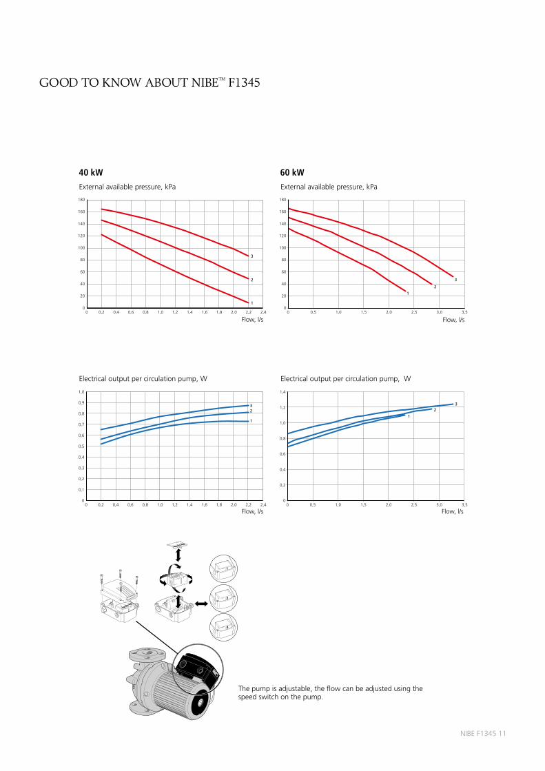
Thepumpisadjustable,theflowcanbeadjustedinmenu5.1.11.
24 kW 30 kW
100
90
80
70
60
50
40
100%
80%
60%
40%30
20
10
00 0,1 0,2 0,3 0,4 0,5 0,6 0,7 0,8 0,9 1,0
Eleffekt per cirkulationspumpW
Flöde, l/s
100
90
80
70
60
50
40
100%
80%
60%
40%
30
20
10
00 0,1 0,2 0,3 0,4 0,5 0,6 0,7 0,8 0,9 1,0
Eleffekt per cirkulationspumpW
Flöde, l/s
90
80
70
60
50
40
100%
80%
60%40%
100%
80%
60%
40%
30
20
10
00 0,2 0,4 0,6 0,8 1,0 1,2 1,4 1,6 1,8 2,0
Externt tillgängligt tryckkPa
2 cirkulationspumpar1 cirkulationspump
Flöde, l/s
90
80
70
60
50
40
100%
80%
60%40%
100%80%
60%
40%
30
20
10
00 0,2 0,4 0,6 0,8 1,0 1,2 1,4 1,6 1,8 2,0
Externt tillgängligt tryckkPa
2 cirkulationspumpar1 cirkulationspump
Flöde, l/s
LEK
GP1
Externalavailablepressure,kPa Externalavailablepressure,kPa
Electricaloutputpercirculationpump,W Electricaloutputpercirculationpump,W
Heating medium side
2circulationpumps1circulationpump
2circulationpumps1circulationpump
Flow,l/s
Flow,l/s
Flow,l/s
Flow,l/s
good to know about nibe™ F1345
Pump capacity diagram

NIBEF13459
40 kW 60 kW
100
90
80
70
60
50
40
100%
80%
60%
40%30
20
10
00 0,1 0,2 0,3 0,4 0,5 0,6 0,7 0,8 0,9 1,0
Eleffekt per cirkulationspumpW
Flöde, l/s
100
90
80
70
60
50
40
100%
80%
60%40%100%80%60%40%
30
20
10
00 0,2 0,4 0,6 0,8 1,0 1,2 1,4 1,6 1,8 2,0
Externt tillgängligt tryckkPa
2 cirkulationspumpar1 cirkulationspump
Flöde, l/s
100
90
80
70
60
50
40
100%
80%
60%
40%30
20
10
00 0,2 0,4 0,6 0,8 1,0 1,2
Eleffekt per cirkulationspumpW
Flöde, l/s
100
90
80
70
60
50
40
100%
80%
60%40%100%80%60%40%
30
20
10
00 0,2 0,4 0,6 0,8 1,0 1,2 1,4 1,6 1,8 2,0
Externt tillgängligt tryckkPa
Flöde, l/s
2 cirkulationspumpar1 cirkulationspump
Thepumpisadjustable,theflowcanbeadjustedinmenu5.1.11.
LEK
GP1
Externalavailablepressure,kPa Externalavailablepressure,kPa
Electricaloutputpercirculationpump,W Electricaloutputpercirculationpump,W
2circulationpumps1circulationpump
2circulationpumps1circulationpump
Flow,l/s
Flow,l/s
Flow,l/s
Flow,l/s
good to know about nibe™ F1345

10NIBEF1345
24 kW 30 kW
200
180
160
140
120
100
80
100%
80%
60%
40%
60
40
20
00 0,2 0,4 0,6 0,8 1,0 1,2 1,4
Eleffekt per cirkulationspumpW
Flöde, l/s
120
100
80
60
40100%
80%
60%40%
100%
80%
60%40%
20
00 0,5 1,0 1,5 2,0 2,5
Externt tillgängligt tryckkPa
Flöde, l/s
2 cirkulationspumpar1 cirkulationspump
200
180
160
140
120
100
80
100%
80%
60%
40%
60
40
20
00 0,2 0,4 0,6 0,8 1,0 1,2 1,4
Eleffekt per cirkulationspumpW
Flöde, l/s
140
120
100
80
60
40100%
80%
60%40%
100%80%
60%40%
20
00 0,5 1,0 1,5 2,0 2,5
Externt tillgängligt tryckkPa
2 cirkulationspumpar1 cirkulationspump
Flöde, l/s
Thepumpisadjustable,theflowcanbeadjustedinmenu5.1.9.
LEKGP2
Externalavailablepressure,kPa Externalavailablepressure,kPa
Electricaloutputpercirculationpump,W Electricaloutputpercirculationpump,W
Brine side
2circulationpumps1circulationpump
2circulationpumps1circulationpump
Flow,l/s
Flow,l/s
Flow,l/s
Flow,l/s
good to know about nibe™ F1345
Pump capacity diagram
NIBEF134511
40 kW 60 kW
1,0
0,8
0,9
0,7
0,6
0,5
0,4
0,3
0,2
0,1
32
1
00 0,4 0,6 0,80,2 1,4 1,6 1,81,21,0 2,2 2,42,0
Eleffekt per cirkulationspumpkW
Flöde, l/s
180
160
140
120
100
80
60
40
3
2
1
20
00 0,4 0,6 0,80,2 1,4 1,6 1,81,21,0 2,2 2,42,0
Externt tillgängligt tryckkPa
Flöde, l/s
1,4
1,2
1,0
0,8
0,6
0,4
0,2
32
1
00 0,5 1,0 1,5 2,0 2,5 3,0 3,5
Eleffekt per cirkulationspumpkW
Flöde, l/s
180
160
140
120
100
80
60
403
2
120
00 0,5 1,0 1,5 3,0 3,52,0 2,5
Externt tillgängligt tryckkPa
Flöde, l/s
LE
K
LEK
Thepumpisadjustable,theflowcanbeadjustedusingthespeedswitchonthepump.
Externalavailablepressure,kPa Externalavailablepressure,kPa
Electricaloutputpercirculationpump,W Electricaloutputpercirculationpump,W
Flow,l/s
Flow,l/s
Flow,l/s
Flow,l/s
good to know about nibe™ F1345

12NIBEF1345
the display
Display unit
Display, A
Instructions,settingsandoperationalinformationareshownonthedisplay.Theeasy-to-readdisplayandmenusystem,facilitatesnavigationbetweenthedifferentmenusandoptionstosetthecomfortorobtaintheinformationyourequire.
Status lamp, B
Thestatuslampindicatesthestatusoftheheatpump.It:
• lightsgreenduringnormaloperation.
• lightsyellowinemergencymode.
• lightsredintheeventofadeployedalarm.
OK button, C
TheOKbuttonisusedto:
• confirmselectionsofsubmenus/options/setvalues/pageinthestartguide.
Back button, D
Thebackbuttonisusedto:
• gobacktothepreviousmenu.
• changeasettingthathasnotbeenconfirmed.
Control knob, E
Thecontrolknobcanbeturnedtotherightorleft.Youcan:
• scrollinmenusandbetweenoptions.
• increaseanddecreasethevalues.
• changepageinmultiplepageinstructions(forexamplehelptextandserviceinfo).
Switch, F
Theswitchassumesthreepositions:
• On( )
• Standby( )
• Emergencymode( )
Alarge,easytoreadmulticoulourdisplaygiveseveryonethechancetomaximizetheenergysavingpotentialofthisexcitinggreentechnology!
B Statuslamp
A Display
C OKbutton
D Backbutton
E Controlknob
F Switch
F1345

NIBEF134513
the display
Menu system Whenthedoortotheheatpumpisopened,themenusystem’sfourmainmenusareshowninthedisplayaswellascertainbasicinformation.
Menu 1 – Indoor climate
Settingandschedulingtheindoorclimate.
Menu 2 – Hot water
Settingandschedulinghotwaterproduction.
Thismenuonlyappearsifawaterheaterisdockedtotheheatpump.
Menu 3 - Info
Display of temperature and other operating information andaccesstothealarmlog.
Menu 4 – Heat pump
Settingtime,date,language,display,operatingmodeetc.
Menu 5 - Service
Advancedsettings.Thesesettingsarenotavailabletotheuser.Themenuisvisiblebypressingthebackbuttonfor7seconds.
Start guideThe first time the heat pump is switched on a start guide isstarted.Thestartguideinstructionsstatewhatneedstocarriedout at the first start together with a run through of the heatpump’sbasicsettings.
Thestartguideensuresthatthestart-upiscarriedoutcorrectlyandcannotbebypassed.Thestartguidecanbestartedlaterinmenu5.7.
Indoortemperature-(ifaroomsensorisconnected)
Outdoortemp.Hotwatertemp.
Extrahotwater(ifactivated)
Estimatedamountofhotwater

14NIBEF1345
Pipe installationPipe installation must be carried out in accordance withcurrentnormsanddirectives.F1345canoperatewithareturntemperatureofupto58°Candanoutgoingtemperaturefromtheheatpumpof65°C.
F1345 is not equipped with shut off valves; these must beinstalledoutsidetheheatpumptofacilitateanyfutureservicing.
Pipe connection (cooling medium)Thepipeconnectionsareontherearoftheheatpump.
Insulateallindoorbrinepipesagainstcondensation.
Markthebrinesystemwiththeantifreezethatisused.
Install the supplied safety valve at the expansion vessel asillustrated in the outline diagram. The entire length of theoverflowwaterpipefromthesafetyvalvesmustbe inclinedtopreventwaterpocketsandmustalsobefrost-free.
Install shutoffvalvesasclose to theheatpumpaspossible sothat the flow to individual cooling modules can be shut off.Extrasafetyvalvesbetweentheparticlefilterandshutoffvalves(accordingtheoutlinediagram)arerequired.
Fitthesuppliedparticlefilterontheincomingbrinepipe.Fitthesuppliednon-returnvalvesontheoutgoingpipe.Inthecaseofconnection to an open groundwater system, an intermediatefrost-protectedcircuitmustbeprovided,becauseof the riskofdirt and freezing in theevaporator. This requiresanextraheatexchanger.
P
Pressure expansion vesselThe brine circuit must be supplied with a pressure expansionvessel.
Thebrinesidemustbepressurisedtoatleast0.05MPa(0.5bar).
Thepressureexpansionvesselshouldbedimensionedassetoutinthefollowingdiagram,topreventoperatingdisturbances.Thediagramscoverthetemperaturerangefrom-10°Cto+20°Cat apre-pressureof0.05MPa (0.5bar) and the safety valve'sopeningpressureof0.3MPa(3.0bar).
Ethanol28%(volumepercent)
Ininstallationswithethanol(28%volumepercent)asthebrine,thepressureexpansionvesselmustbedimensionedaccordingtothefollowingdiagram.
Ethylene glycol 40% (volume percent)
Ininstallationswithethyleneglycol(40%volumepercent)asthebrinethepressureexpansionvesselmustbedimensionedaccordingtothefollowingdiagram.
0 200 400 600 800 1000 1200 1400 1600 1800 20000
10
20
30
40
50
60
70
80
90
100
Volumepressureexpansionvessel(l)
Totalvolumerefrigerantinsystem(l)
30
0
40
50
60
0
10
20
100 200 300 400 500 600 700 800 900 1000 1100 1200 1300 1400 1500
Volumepressureexpansionvessel(l)
Totalvolumerefrigerantinsystem(l)
Ethylene glycol 40% (volume percent)
Ininstallationswithethyleneglycol(40%volumepercent)asthebrinethepressureexpansionvesselmustbedimensionedaccordingtothefollowingdiagram.
installation
Note!Notethatcondensationmaydripfromthelevel vessel.Positionthevesselsothatthisdoesnotharm otherequipment.

NIBEF134515NIBEVPB200N15
Connection of external brine pump (only 40 and 60 kW)Installthebrinepump(GP16)accordingtothecirculationpumpmanualforconnectionofincomingbrine(EP14-XL6)and(EP15-XL6)betweentheheatpumpandshutoffvalve(seeimage).
Pipe connection (heating medium)Connecting the climate system
AclimatesystemisasystemthatregulatesindoorcomfortwiththehelpofthecontrolsysteminF1345andforexampleradiators,underfloorheating/cooling,fanconvectorsetc.
Thepipeconnectionsareontherearoftheheatpump.
Install the necessary safety equipment and shut off valves(installedasclosetotheheatpumpaspossiblesothattheflowtoindividualcoolingmodulescanbeshutoff).
Fitthesuppliedparticlefilterontheincomingpipe.
The safety valve must have a maximum 0.6 MPa ( 6.0 bar)openingpressureandbeinstalledontheheatingmediumreturn.The entire length of the overflow water pipe from the safetyvalvesmustbeinclinedtopreventwaterpocketsandmustalsobefrost-free.
Whenconnectingtoasystemwiththermostatsonallradiators,areliefvalvemustbefitted,orsomeofthethermostatsmustberemovedtoensuresufficientflow.
Fitthesuppliednon-returnvalvesontheoutgoingpipe.
Installtheventvalvesintheclimatesystemifnecessary.
CAUTION!Whennecessaryyoushouldinstallventingvalvesintheclimatesystem.
CAUTION!Theheatpumpisdesignedsothatheatingproductioncanoccurwithoneortwocoolingmodules.Thishoweverentailsdifferentpipeorelectricalinstallations.
40kW24-30kW 60kW
GP16
Pipe connection (water heater)• Anydockedhotwaterheatermustbefittedwithnecessary
setofvalves.
• Themixingvalvemustbeinstalledifthesettingischangedsothatthetemperaturecanexceed60°C.
• Thesettingforhotwaterismadeinmenu5.1.1.
• Thesafetyvalvemusthaveamaximumopeningpressureinaccordancewiththewaterheatermanualandbeinstalledontheincomingdomesticwaterline.Theentirelengthoftheoverflowwaterpipefromthesafetyvalvesmustbeinclinedtopreventwaterpocketsandmustalsobefrost-free.
Fixed condensing
IfF1345istoworktowardsthewaterheaterwithfixedcondensingyoumustconnectanexternalflowsensor(BT25)accordingtothedescrip-tionintheinstallerhandbookInaddition,menusettingsmustbemade(seeinstallerhandbook).
CAUTION!Theheatpump/systemisdesignedsothathotwaterproductioncanoccurwithoneorseveralcoolingmodules.Thishoweverentailsdifferentpipeorelectricalinstallations.
installation
16NIBEF1345
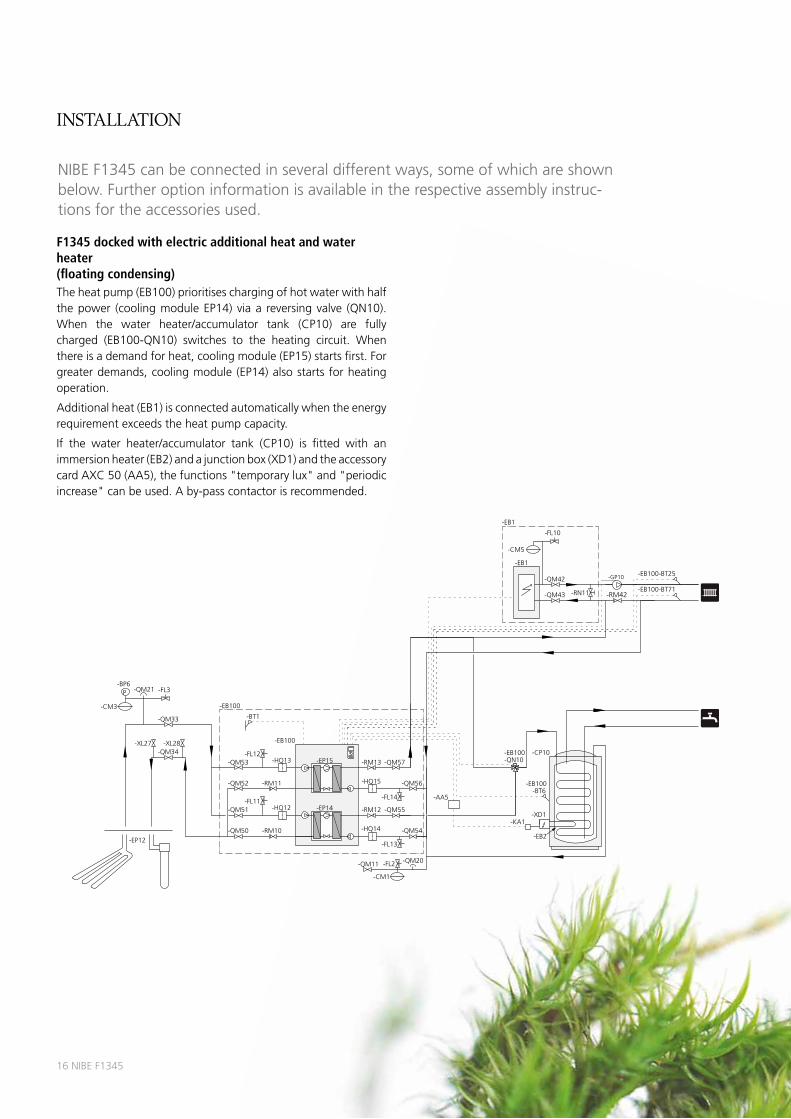
NIBEF1345canbeconnectedinseveraldifferentways,someofwhichareshownbelow.Furtheroptioninformationisavailableintherespectiveassemblyinstruc-tionsfortheaccessoriesused.
-BT6
-CP10
-EP12
-CM3
P-BP6
-QM21 -FL3
-XL28-XL27
-QM33
-FL2
-CM1
-QM11 -QM20
-QM34
-EB100-BT25
-EB100-BT71
-FL12
-FL11
-FL13
-FL14
-QM54
-QM55
-QM56
-QM57
-QM50
-QM51
-QM52
-QM53
-RM11
-RM10
-BT1
-EB100
-EB100
-EP15
-EP14
-HQ15
-HQ14
-RM12
-RM13-HQ13
-HQ12
-EB100
-CM5
-FL10
-QM42
-QM43
-EB1
-EB1
-EB2
-XD1
-RN11
-QN10-EB100
-GP10
-KA1
-AA5
-RM42
F1345 docked with electric additional heat and water heater (floating condensing)Theheatpump(EB100)prioritiseschargingofhotwaterwithhalfthepower (coolingmoduleEP14)viaa reversingvalve (QN10).When the water heater/accumulator tank (CP10) are fullycharged (EB100-QN10) switches to the heating circuit. Whenthereisademandforheat,coolingmodule(EP15)startsfirst.Forgreaterdemands,coolingmodule(EP14)alsostartsforheatingoperation.
Additionalheat(EB1)isconnectedautomaticallywhentheenergyrequirementexceedstheheatpumpcapacity.
If the water heater/accumulator tank (CP10) is fitted with animmersionheater(EB2)andajunctionbox(XD1)andtheaccessorycardAXC50(AA5),thefunctions"temporarylux"and"periodicincrease"canbeused.Aby-passcontactorisrecommended.
installation

NIBEF134517
2x F1345 docked with oil addition, pool and water heater (floating condensing)Theheatpump (EB100)prioritises chargingofhotwaterwithhalf the power (cooling module EP14) via a reversing valve(EB100-QN10).Whenthewaterheater/accumulatortank(CP10and CP11) are fully charged (EB100-QN10) switches to theheating circuit. The other half of the output (cooling moduleEP15)prioritisespoolheatingviaareversingvalve(CL11-QN19).Whenthepoolisheated(CL11-QN19)switchestotheheatingcircuit.Whenthereisademandforheat,coolingmodule(EP15)startsinheatpump(EB101)first.Forgreaterdemands,coolingmodule(EP14)alsostartsin(EB101)forheatingoperation.
Additional heat (EM1) is connected automatically when theenergyrequirementexceedstheheatpumpcapacity.
If the water heater/accumulator tank (CP10) is fitted with animmersionheateranda junctionbox the function"temporarylux"isused.Aby-passcontactorisrecommended.
-HQ13
-RM11
-HQ12
-RM10
-HQ15
HQ14
-RM12
-RM13
-EB101
-EB101
-EP15
-EP14
-EP12
-CM3
P-BP6
-QM21 -FL3
-XL28-XL27
-QM33
-EB100-BT25
-FL2
-CM1
-QM11 -QM20
-EB100-BT71
-QM34
-QM54
-QM55
-QM56
-QM57
-FL13
-FL14
-FL13
-FL14
-QM50
-QM51
-QM52
-QM53
-FL11
-FL12
-QM54
-QM55
-QM56
-QM57
-QM50
-QM51
-FL11
-QM52
-QM53
-FL12
-QN10
-QN19
-CL11
-AA5
-RN42
-EP5
-GP9 -BT51 -HQ41 POOL
-BT6
-CP10
-RN63
-RN62
-CP11
-RN61
-RN60
-RM42
-GP10-QN11
-BT52-AA5-CM5
-FL10
-EM1
-EM1
-KA1 -BT3
-BT2
-EP21
-GP20
-QN25
-AA5
-HQ13
-EB100
-EB100
-RM11
-HQ12
-RM10
-BT1
-EB100
-EB100
-EP15
-EP14
-HQ15
-HQ14
-RM12
-RM13
-AA5 -GP11
-RN41
-RM43
-EB10
-FQ1 -BT70
installation

18NIBEF1345
Inspection of the installationCurrent regulations require the heating installation to beinspected before it is commissioned. The inspection mustbe carried out by a suitably qualified person and should bedocumented.Theaboveappliestoclosedheatingsystems.Iftheheatpumpisreplaced,theinstallationmustbeinspectedagain.
Guideline values for collectors
Type Surface ground heating, recommended collector length
Ground-source heating, recommended active drilling depth
24 3x350–3x400m 2x180–3x180m
30 3x450–4x450m 3x150–5x150m
40 4x500–6x500m 4x170–5x200m
60 6x450–8x450m 6x150–8x180m
Forusewith40x2.4PN6.3PEMhose.
This are rough example values. On installation the correctcalculationsmustbemadeaccordingtolocalconditions.
Thelengthofthecollectorhosevariesdependingontherock/soilconditions,climatezoneandontheclimatesystem(radiatorsorunderfloorheating).
Maxlengthpercoilforthecollectorshouldnotexceed500m.
The collectors must always be connected in parallel with thepossibilityofadjustingtheflowfortherelevantcoil.
For surfacesoilheat, thehoseshouldbeburiedatadepthofabout1metreandthedistancebetweenthehosesshouldbeatleast1metre.
Forseveralboreholes,thedistancebetweentheholesmustbeatleast15m.
Ensurethecollectorhoserisesconstantlytowardstheheatpumptoavoidairpockets. If this isnotpossible,airventsshouldbeused.
As the temperatureof thebrine systemcan fallbelow0°C itmustbeprotectedagainst freezingdown to -15 °C.One litreofreadymixedbrinepermeterofcollectorhose(applieswhenusingPEM-hose40x2.4PN6.3)isusedasaguidevaluewhenmakingthevolumecalculation.
Control, generalThe indoor temperature depends on several factors. Sunlightand heat emissions from people and household machines arenormallysufficienttokeepthehousewarmduringthewarmerpartsoftheyear.Whenitgetscolderoutside,theclimatesystemmustbestarted.Thecolderitisoutside,thewarmerradiatorsandfloorheatingsystemmustbe.
The heat pump is controlled by built-in sensors for flow andreturnbrinetemperatures (collector).Brinereturntemperaturescan, if so required, be limited to a minimum (e.g. for groundwatersystems).
Control of the heat production is performed based on the"floatingcondensing"principle,i.e.thetemperaturelevelneededforheatingataspecificoutdoortemperatureisproducedguidedbycollectedvaluesfromtheoutdoorandflowsensors.Theroomtemperaturesensorcanalsobeusedtocompensatethedeviationinroomtemperature.
F1345canbedockedtoanexternalunitwith itsownheatingcontrols. In that case, the heat pump delivers heat up to afixed temperature level. This is known as “Fixed condensing”.Theautomaticheatingcontrolsystem is thencontrolledbytheexternalunit’sregulationdevice.
installation
NIBEF134519
Basic functionsHeat production
F1345 is equipped with an outdoor temperature controlledheatingcontrolsystem.Thismeansthatthesupplyofheattothehouseisregulatedinaccordancewiththechosensettingoftheregulatingcurve(curveslopeandoffset).Afteradjustment,thecorrectamountofheatfortheoutsidetemperatureissupplied.The flow line temperature of the heat pump will hunt aroundthetheoreticallyrequiredvalue.Forsubnormaltemperaturesthecontrolsystemcalculatesaheatingdeficitintheformof"degree-minutes" which means that heating production is accelerated.The larger the subnormal temperature, the greater the heatproduction.
Heatproductioncantakeplacewithoneorseveralcompressors.
Hot water production
ThisfunctionrequiresaccessoryVST20.
IfthewaterheaterisdockedtoF1345whenthereisademandforhotwater, theheatpumpgivesthispriorityanddevoteshalf itsoutputtowaterheating.Heating isproducedby the secondcompressor in thismode.Maximum time forhotwater charging canbeadjustedinthemenusystem.Afterthis,heatingisproducedbyboththecompressors for the remaining period of time before furtherwaterheatingcantakeplace.
Withtwoormorecompressorsconnectedforwaterheatingthisisengagedanddisengagedautomaticallybythecontrolsystemondemand.AreversingvalveisrequiredforeachF1345thatistochargehotwater.
Hotwaterchargingstartswhenthehotwatersensorhasfallentothesetstarttemperature.Hotwaterchargingstopswhenthehotwatertemperatureonthehotwatersensor(BT6)hasbeenreached.
Foroccasionalhigherdemandforhotwater,thetemporary luxfunctioncanbeusedtoraisethetemperaturefor3–12hours(selectedinthemenusystem).
Own curve
F1345haspre-programmednonlinearheatingcurves.It isalsopossibletocreateyourowndefinedcurve.This isan individuallinearcurvewithonebreakpoint.Youselectabreakpointandtheassociatedtemperatures.
Under floor drying
F1345 has an integrated floor drying function. This allows forcontrolled drying of a concrete slab. It is possible to createyourownprogramand to followapre-programmed timeandtemperatureschedule.
LEK
LEK
LEK
Brine pump
Thebrinepumps(40or60kWhave1brinepump)normallyfollowtheoperationoftheheatpump.Thereisaspecialoperatingmodeforcon-tinuousoperationfor10days,followedbyreturntonormalmode(thismaybeusedbeforestablecirculationhasbeenestablished).
Alarm indications
Thestatuslamplightsredintheeventofanalarmandthedisplayshowsdetailedinformationdependingonthefault.Analarmlogiscre-atedwitheachalarmcontaininganumberoftemperatures,timesandthestatusofoutputs.
Additional heat only
F1345canbeusedexclusivelywithanadditionalheatertoproduceheat,forexamplebeforethecollectorinstallationiscomplete.
Room control
F1345canbesupplementedwitharoomsensor(BT50).Theroomtem-peraturesensorhasuptothreefunctions:
1. Showcurrentroomtemperatureintheheatpump'sdisplay.
2. Optionofchangingtheroomtemperaturein°C.
3. Makesitpossibletochange/stabilisetheroomtemperature.
Installthesensorinaneutralpositionwherethesettemperatureisrequired.Asuitableplaceisonafreeinnerwallinahallapprox.1.5mabovethefloor.Itisimportantthatthesensorisnotobstructedfrommeasuringthecorrectroomtemperaturebybeinglocated,forexample,inarecess,betweenshelves,behindacurtain,aboveorclosetoaheatsource,inadraftfromanexternaldoororindirectsunlight.Closedradiatorthermostatscanalsocauseproblems.
Theheatpumpoperateswithoutthesensor,butifonewishestoreadofftheaccommodation'sindoortemperatureinF1345'sdisplaythesen-sormustbeinstalled.
External control (AUX input)
F1345canbecontrolledusingsignalsfromexternalsystems(forexam-pleDUC)connectedtothreesoftwarecontrolledinputs(AUXinputs).ThealarmandtimeconditionsinF1345overridetheexternalcontrol.
Thefollowingfunctionscanbecontrolled:
• Blockingofthecompressors-EP14and-EP15
• Blockingadditionalheat
• Blockingheating
• Tariffblocking
• Activationoftemporarylux(extrahotwater)
• Externaladjustmentofflowtemperature
• Forcedcontrolofbrinepump(s)
• Activatingfanspeed(requiresaccessoryNIBEFLM)
Allcontrolsignalsshouldoccurwithpotential-freerelays.
installation

20NIBEF1345
Step controlled additional heat
Heatpumpsarenotusuallydimensionedtoprovidetheentireheatout-putrequirement,whichiswhyadditionaloutputisnecessaryduringcolddays.Theexternalstepcontrolledadditionalheater(ifconnected)isau-tomaticallyswitchedon(indifferentsteps)iftheoutputisnotsufficienttoreachthetemperaturelevelsrequestedbythecontrolcomputer.
F1345provides230Vcontrolsignalsfortheadditionalheat,thatissignalsforcontrollingexternalrelays,contactorsetc,butnottosupplythemwithpower.
Externalstepcontrolledadditionalheatcanbecontrolledbyuptothreepotentialfreerelaysintheheatpump(3steplinearor7stepbinary).WiththeAXC50accessoryafurtherthreepotentialfreerelaysareusedforadditioncontrol,whichthengivesmax3+3linearor7+7binarysteps.
Stepinoccurswithatleast1minuteintervalandstepoutswithatleast3secondsinterval.
Master/Slave
Severalheatpumps(F1345)canbeinterconnectedbyselectingoneheatpumpasmasterandtheothersasslaves.
Theheatpumpisalwaysdeliveredasmasterandupto8slavescanbeconnectedtoitandsupplyupto540kW(with9xF134560kW)inthesamesystem.Insystemswithseveralheatpumpseachpumpmusthaveauniquename,thatisonlyoneheatpumpcanbe"Master"andonlyonecanbeforexample"Slave5".
Externaltemperaturesensorsandcontrolsignalsmustonlybeconnect-edtothemaster,exceptforexternalcontrolofthecompressormoduleandreversingvalve(s)(QN10)thatcanbeconnectedonetoeachheatpump.
Software controlled output (AUX output)
Itispossibletohaveanexternalconnectionthroughtherelayfunctionviaapotentialfreevariablerelay(max2A)ontheX5terminalblock.
Optionalfunctionsforexternalconnection:
• Indicationofbuzzeralarm(preselectedatthefactory).
• Controllinggroundwaterpump.
• Coolingmodeindication(onlyappliesifaccessoriesforcoolingarepresentoriftheheatpumphastheintegratedcoolingfunction).
• Controlofcirculationpumpforhotwatercirculation.
• Externalcirculationpump(forheatingmedium).
• IfanyoftheaboveisinstalledtoterminalblockX5itmustbeselectedinthecontrolsystem.
TheaccessorycardisrequirediftwoormoreoftheabovefunctionsaretobeconnectedtoterminalblockX5atthesametime.
Load monitor
Whenmanypowerconsumersareconnectedinthepropertyatthesametimeastheelectricadditionalheatisoperating,thereisariskoftheproperty'smainfusetripping.Theheatpumphasintegratedloadmonitorsthatcontroltheelectricalstepsfortheelectricaladditionalheatbydisconnectingstepbystepineventofoverloadinaphase.Reconnec-tionoccurswhenothercurrentconsumptionisreduced.
Acurrentsensorshouldbeinstalledoneachincomingphaseconductorintothedistributionboxtomeasurethecurrent.Thedistributionboxisanappropriateinstallationpoint.
USB service outlet
F1345isequippedwithaUSBsocketinthedisplayunit.ThisUSBsocketcanbeusedtoconnectaUSBmemorysticktoupdatethesoftware,saveloggedinformationandhandlethesettingsinF1345.
LE
K
installation
NIBEF134521
Extended functionsPool
ThisfunctionrequiresaccessoryPOOL40.
Areversingvalvecanbeconnectedtocontrolpart,orall,oftheheatingmediumflowtoapoolexchanger.Thereversingvalve,orifsodesiredthereversingvalves(althoughusingthesamecontrolsignal),is/arein-stalledontheheatingmediumcircuitwhichnormallygoestoaradiatorsystem.Youdetermineinthecontrolsystemhowmanycompressorsarepermittedtoworkwiththepool.Externalcirculationpump(GP10)mustbeinstalledforpooloperation.
Duringpoolheatingtheheatingmediumiscirculatedbetweentheheatpumpandthepoolexchangerusingtheheatpump'sinternalcirculationpumps.
Theexternalcirculationpumpcirculatestheheatingmediumwaterintheclimatesystemandtheadditionalheatcanbeengagedasneces-saryatthesametimeastheexternalflowsensorcontinuallymeterstheheatingdemandofthehouse.
UptotwodifferentpoolsystemscanbeconnectedtoF1345andcon-trolledindividually,itdoesrequiretwoPOOL40-accessories.
Extra climate system
ThisfunctionrequirestheECS40/ECS41orAXC50accessoryiflargerseparateshuntvalvesareneeded.
Ashuntvalve,flowandreturnsensorandacirculationpumpareconnectedtoasecondheatingcircuitwithalowertemperaturedemand(e.g.underfloorheatingsystem).Thetemperatureintheextraclimatesystemiscontrolledbytheheatpumpandtheshuntvalvebyoffsettingtheheatcurve(eachclimatesystemhasitsownheatcurve),roomsensororroomunit.
Upto3additionalclimatesystemscanbeconnectedtotheheatpump.
Hot water comfort
ThisfunctionrequirestheaccessoryAXC50whichgivesthepossibilityoftemporarylux,mixingvalveandhotwatercirculation(anAXC50foreachaccessoryfunctionthatistobeused).
Temporary lux (extra hot water)
ThisfunctionrequirestheaccessoryAXC50.Ifanim-mersionheaterisinstalledinthetankitcanbepermit-tedtoproducehotwateratthesametimeastheheatpumpprioritisesheating.
Mixing valve
ThisfunctionrequirestheaccessoryAXC50.Atemperaturesensorreadsthetemperatureoftheoutgoingwatertothehotwatertapsandad-juststhemixingvalvefromthehotwaterheateruntilthesettempera-ture(inthecontrolsystem)hasbeenreached.
Hot water circulation (VVC)
ThisfunctionrequirestheaccessoryAXC50.Onepumpcanbecon-trolledforthecirculationofthehotwaterduringselectableperiods.
Cooling
TheaccessoryAXC50maybeneededfordistributionofcoolingtotheclimatesystem.
Passive cooling (4-pipe)
ThisfunctionrequirestheaccessoryAXC50(anAXC50foreachaccessoryfunctionthatistobeused).
Thecoolingsystemisconnectedtotheheatpumpcol-lectorcircuit,throughwhichcoolingissuppliedfromthecollectorviathecirculationpumpandtheshuntvalve.
Whencoolingisrequired(activatedfromtheoutdoorsensorandanyroomsensor)thereversingvalveandthecirculationpumpareactivated.Theshuntvalveregulatessothatthecoolingsensorreachesthecurrentsetpointvaluecorrespondingtotheoutdoortemperatureandthesetmin.valueforthecoolingtemperature(topreventcondensation).
Passive/active cooling (4-pipe)
Thisfunctionrequiresreversingvalveforcooling,circu-lationpump,shuntvalveandaccessoryACS45.
Thisfunctionmakesbothheatandcoolingproductionindependentlyofeachotherpossible.
Thecoolingsystemsuppliescoolingfromthecollectorcircuitusingacirculationpumpviaashuntvalve.
Passivecoolingoccurswithoutthecompressorrunning,whileactivecoolingoccurswhenthecompressorisrunning.
Fortheinstallationtoworktheheatingmediummustflowfreely,forexampleusingUKV.
Operatingmodecoolingisactivatedbythetemperatureoftheoutdoorsensorandanyroomtemperaturesensorsorroomunits.
Whencoolingisrequiredthecoolingreversingvalveandthecirculationpumpareactivated.Theshuntregulatesaccordingtothecoolingsensorandacoolingsetpointvaluethatisdeterminedbytheselectedcoolingcurveandoffset.Degreeminutesarecalculatedinresponsetothevalueonthebrineoutexternaltemperaturesensorandthecoolingsetpointvalue.Thedegreeminutevaluedeterminesinwhichcoolingmodetheinstallationisaccordingtothemenusettings.
Passive cooling (2-pipe)
ThisfunctionrequirestheaccessoryAXC50(anAXC50foreachaccessoryfunctionthatistobeused).
Thecollectorcircuitisconnectedtoaheatexchangerviaareversingvalve.Theothersideoftheexchangerisconnectedtotheheatingmediumcircuitviaashuntvalveandacirculationpump.
Whencoolingisrequired(activatedfromtheoutdoorsensorandanyroomsensororroomunit)thereversingvalveandthecirculationpumpareactivated.Theshuntvalveregulatessothatthecoolingsensorreachesthecurrentsetpointvaluecorrespondingtotheoutdoortem-peratureandthesetmin.valueforthecoolingtemperature(topreventcondensation).
LEK
LEK
LE
K
GR
UN
DFO
SType
UP
S25 -
60
13
0P
/N:5
9526447
230V
-
HE
JS
AN
PC
;001
7N
IBD
K50H
z
IP
44
TF
110
Cla
ss
HM
ax. 1
0b
ar
2.5
uF
45
0.2
065
0.3
090
0.4
0
1m(A
)P,
(W)
LEK
LEK
LEK
LEK
LEK
LEK
installation
22NIBEF1345
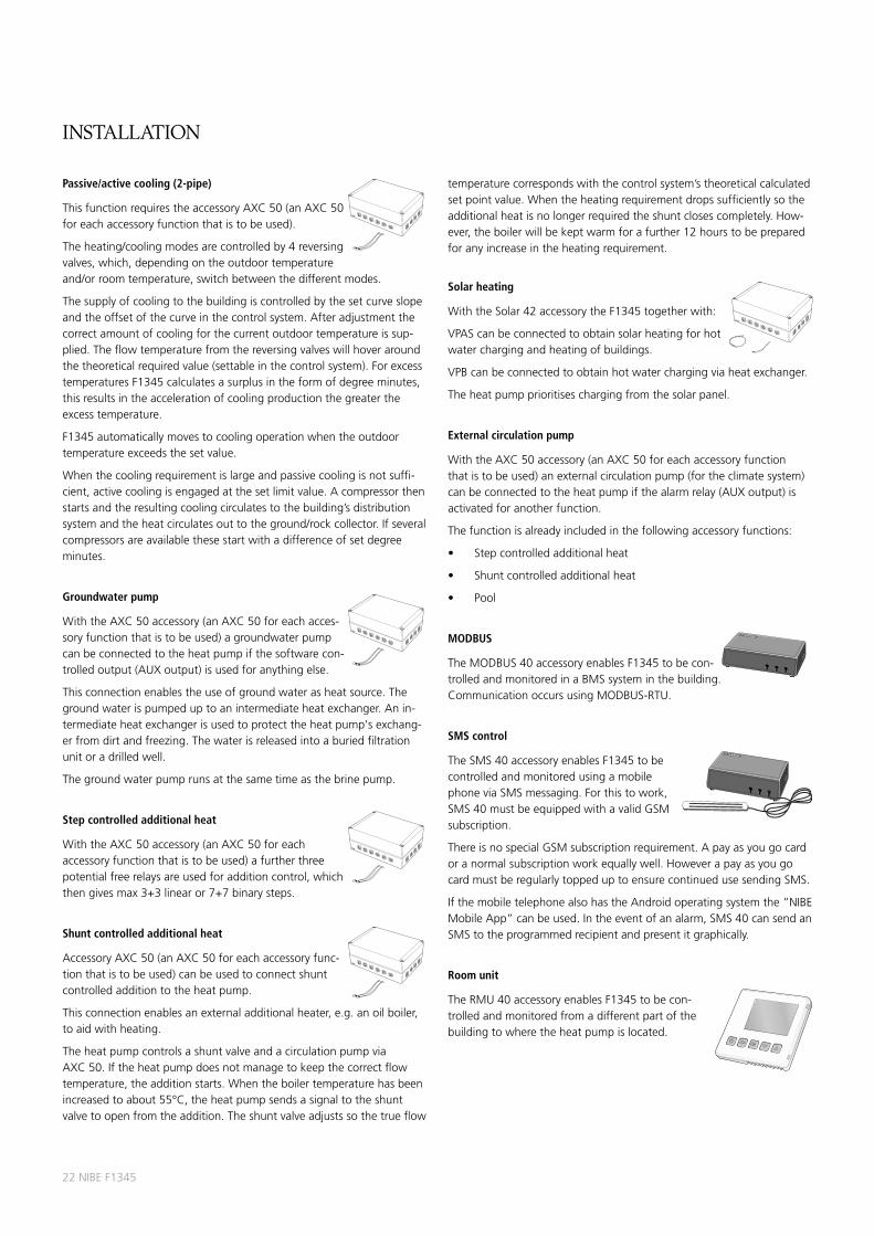
Passive/active cooling (2-pipe)
ThisfunctionrequirestheaccessoryAXC50(anAXC50foreachaccessoryfunctionthatistobeused).
Theheating/coolingmodesarecontrolledby4reversingvalves,which,dependingontheoutdoortemperatureand/orroomtemperature,switchbetweenthedifferentmodes.
Thesupplyofcoolingtothebuildingiscontrolledbythesetcurveslopeandtheoffsetofthecurveinthecontrolsystem.Afteradjustmentthecorrectamountofcoolingforthecurrentoutdoortemperatureissup-plied.Theflowtemperaturefromthereversingvalveswillhoveraroundthetheoreticalrequiredvalue(settableinthecontrolsystem).ForexcesstemperaturesF1345calculatesasurplusintheformofdegreeminutes,thisresultsintheaccelerationofcoolingproductionthegreatertheexcesstemperature.
F1345automaticallymovestocoolingoperationwhentheoutdoortemperatureexceedsthesetvalue.
Whenthecoolingrequirementislargeandpassivecoolingisnotsuffi-cient,activecoolingisengagedatthesetlimitvalue.Acompressorthenstartsandtheresultingcoolingcirculatestothebuilding’sdistributionsystemandtheheatcirculatesouttotheground/rockcollector.Ifseveralcompressorsareavailablethesestartwithadifferenceofsetdegreeminutes.
Groundwater pump
WiththeAXC50accessory(anAXC50foreachacces-soryfunctionthatistobeused)agroundwaterpumpcanbeconnectedtotheheatpumpifthesoftwarecon-trolledoutput(AUXoutput)isusedforanythingelse.
Thisconnectionenablestheuseofgroundwaterasheatsource.Thegroundwaterispumpeduptoanintermediateheatexchanger.Anin-termediateheatexchangerisusedtoprotecttheheatpump'sexchang-erfromdirtandfreezing.Thewaterisreleasedintoaburiedfiltrationunitoradrilledwell.
Thegroundwaterpumprunsatthesametimeasthebrinepump.
Step controlled additional heat
WiththeAXC50accessory(anAXC50foreachaccessoryfunctionthatistobeused)afurtherthreepotentialfreerelaysareusedforadditioncontrol,whichthengivesmax3+3linearor7+7binarysteps.
Shunt controlled additional heat
AccessoryAXC50(anAXC50foreachaccessoryfunc-tionthatistobeused)canbeusedtoconnectshuntcontrolledadditiontotheheatpump.
Thisconnectionenablesanexternaladditionalheater,e.g.anoilboiler,toaidwithheating.
TheheatpumpcontrolsashuntvalveandacirculationpumpviaAXC50.Iftheheatpumpdoesnotmanagetokeepthecorrectflowtemperature,theadditionstarts.Whentheboilertemperaturehasbeenincreasedtoabout55°C,theheatpumpsendsasignaltotheshuntvalvetoopenfromtheaddition.Theshuntvalveadjustssothetrueflow
temperaturecorrespondswiththecontrolsystem’stheoreticalcalculatedsetpointvalue.Whentheheatingrequirementdropssufficientlysotheadditionalheatisnolongerrequiredtheshuntclosescompletely.How-ever,theboilerwillbekeptwarmforafurther12hourstobepreparedforanyincreaseintheheatingrequirement.
Solar heating
WiththeSolar42accessorytheF1345togetherwith:
VPAScanbeconnectedtoobtainsolarheatingforhotwaterchargingandheatingofbuildings.
VPBcanbeconnectedtoobtainhotwaterchargingviaheatexchanger.
Theheatpumpprioritiseschargingfromthesolarpanel.
External circulation pump
WiththeAXC50accessory(anAXC50foreachaccessoryfunctionthatistobeused)anexternalcirculationpump(fortheclimatesystem)canbeconnectedtotheheatpumpifthealarmrelay(AUXoutput)isactivatedforanotherfunction.
Thefunctionisalreadyincludedinthefollowingaccessoryfunctions:
• Stepcontrolledadditionalheat
• Shuntcontrolledadditionalheat
• Pool
MODBUS
TheMODBUS40accessoryenablesF1345tobecon-trolledandmonitoredinaBMSsysteminthebuilding.CommunicationoccursusingMODBUS-RTU.
SMS control
TheSMS40accessoryenablesF1345tobecontrolledandmonitoredusingamobilephoneviaSMSmessaging.Forthistowork,SMS40mustbeequippedwithavalidGSMsubscription.
ThereisnospecialGSMsubscriptionrequirement.Apayasyougocardoranormalsubscriptionworkequallywell.HoweverapayasyougocardmustberegularlytoppeduptoensurecontinuedusesendingSMS.
IfthemobiletelephonealsohastheAndroidoperatingsystemthe”NIBEMobileApp”canbeused.Intheeventofanalarm,SMS40cansendanSMStotheprogrammedrecipientandpresentitgraphically.
Room unit
TheRMU40accessoryenablesF1345tobecon-trolledandmonitoredfromadifferentpartofthebuildingtowheretheheatpumpislocated.
LEK
LEK
LEK
LEK
LEK
LEK
LE
K
LEK
installation

NIBEF134523
Air collector
ThisfunctionrequiresaccessoryNIBEAMB30.
AMB30isaheatabsorbentairmodule.Theairmoduleismostsuitablewhentheground-/rockcol-lectordoesnothavethecapacitythattheinstallationrequires.
OutdooraircollectorAMB30isconnectedtoNIBEF1345foronlyout-doorairoperationorincombinationwithrock/groundcollector(hybridoperation).
Outdoor air operation
DuringoutdoorairoperationtheAMB30usestheoutdoorairasaheatsourceandoperationispermitteddowntoanoutdoorairtemperatureofapprox-7ーC.OutgoingbrinefromtheF1345isconnecteddirectlytotheairmodule.Whentheoutdoorairtemperatureislowerthanthedimensionedbalancetemperature(thelowesttemperaturewheretheheatpumpcanmanagealltheheating)theadditionalheatmustbeac-cessibletosupplementtheheatpump.
Hybrid operation
Whentheoutdoorairtemperatureishigherthan12°CthecontrolswitchesthereversingvalvestooperationwithonlyAMB30.Whentheoutdoorairtemperatureisbetweenapprox.0and10°Cthecon-trolsswitchesthereversingvalvetooperationwithbothAMB30andground/rockcollector(hybridoperation).Atasetmin.differencethecontrolswitchestooperationwithonlyground/rockcollector.
LE
K
installation

Type 24 30 40 60Output data at nom flow according to EN 255 Refers to performance of heat pump without circulation pumps
0/35Specifiedoutput kW 23,2 31,3 40,0 57,8
Coolingoutput kW 18,4 24,6 31,8 45,1
Electricaloutput kW 4,84 6,67 8,17 12,7
COPEN255 - 4,79 4,69 4,89 4,55
0/50Specifiedoutput kW 22,0 30,4 38,7 54,8
Coolingoutput kW 15,6 21,6 28,0 38,4
Electricaloutput kW 6,41 8,80 10,6 16,4
COPEN255 - 3,43 3,46 3,63 3,34
Output data according to EN 145110/35Specifiedoutput(PH) kW 22,5 30,7 40,0 57,7
Electricaloutput(PE) kW 5,05 7,00 8,88 14,1
COPEN14511 - 4,42 4,36 4,51 4,10
0/45Specifiedoutput(PH) kW 21,5 30,1 39,0 55,1
Electricaloutput(PE) kW 6,08 8,47 10,6 16,5
COPEN14511 3,50 3,53 3,68 3,35
10/35Specifiedoutput(PH) kW 30,1 40,3 51,8 78,2
Electricaloutput(PE) kW 5,39 7,80 9,70 16,1
COPEN14511 - 5,54 5,15 5,32 4,84
10/45Specifiedoutput(PH) kW 28,7 39,5 50,9 72,7
Electricaloutput(PE) kW 6,44 9,25 11,7 18,4
COPEN14511 4,43 4,24 4,34 3,95
Electrical dataRatedvoltage 400V3NAC50Hz
Maxoperatingcurrent,heatpump3) Arms 19,4 24,8 30,9 47,1
Maxoperatingcurrent,compressor Arms 7,8 10,5 13,9 19,9
Recommended fuse protection A 25 30 35 50
Startcurrent Arms 29 34 42 53
Maxpermittedimpedanceatconnectionpoint1) ohm - - - 0,4
Power,Brinecirculationpump3) W 10-370 10-370 735-890 1150-1290
Power,Heatingcirculationpumps W 5-174 5-174 5-174 5-174
IPclass IP21
Refrigerant circuitTypeofrefrigerant R407C R410A
Volume kg 2x2.2 2x2.3 2x2.4 2x2.4
Cut-outvaluepressostatHP bar 32 42
DifferencepressostatHP bar -7
Cut-outvaluepressostatLP bar 0,8 2
DifferencepressostatLP bar 0,7
Cut-outvalue,pressuretransmitterLP(withoutAMB30) bar 1,3 3,5
Cut-outvalue,pressuretransmitterLP(withAMB30) bar 0,8 2
Difference,pressuretransmitterLP bar 0,1
24NIBEF1345
IP21
technical speciFications
1) Max.permittedimpedanceinthemainsconnectedpointinaccordancewithEN61000-3-11.Startcurrentscancauseshortvoltagedipsthatcouldaffectotherequipmentinunfavourableconditions.Iftheimpedanceinthemainsconnectionpointishigherthanthatstateditispossiblethatinterferencewilloccur.Iftheimpedanceinthemainsconnectionpointishigherthanthatstatedcheckwiththepowersupplierbeforepurchasingtheequipment.
2) Withfeetdismantledtheheightisapprox.1650mm.3) Thistechnicaldataappliestothebrinepumpsuppliedfor40and60kW.
Type 24 30 40 60
Brine circuitMaxsystempressurebrine bar 3
Minflow l/s 0,92 1,23 1,59 2,26
Nominalflow l/s 1,18 1,62 2,09 2,90
Maxexternalavail.pressatnomflow3) kPa 92 75 92 72
Max/MinIncomingBrinetemp °C seediagram
Min.outgoingbrinetempwithout/withAMB30 °C -12/-14
Heating medium circuitMaxsystempressureheatingmedium bar 4
Minflow l/s 0,37 0,50 0,64 0,92
Nominalflow l/s 0,54 0,73 0,93 1,34
Maxexternalavail.pressatnomflow kPa 78 72 70 50
Max/Minheatingmediumtemp °C seediagram
Sound power level (LWA) according to EN 12102 at 0-35 dB(A) 47 47 47 47
Sound pressure level (LON) calculated values according to EN ISO 11203 at 0/35 and 1m range dB(A) 32 32 32 32
Pipe connectionsBrineextdiam.CUpipe G50(2"external)
Heatingmediumextdiam.,CUpipes G50(2"external)
Dimensions and weightWidth mm 600
Depth mm 620
Height mm 1800
Requiredceilingheight2) mm 1950
Weightcompleteheatpump kg 325 335 352 353
Weightpercoolingmodule kg 130 135 143,5 144
Part no. 065110 065111 065112 065113
NIBEF134525
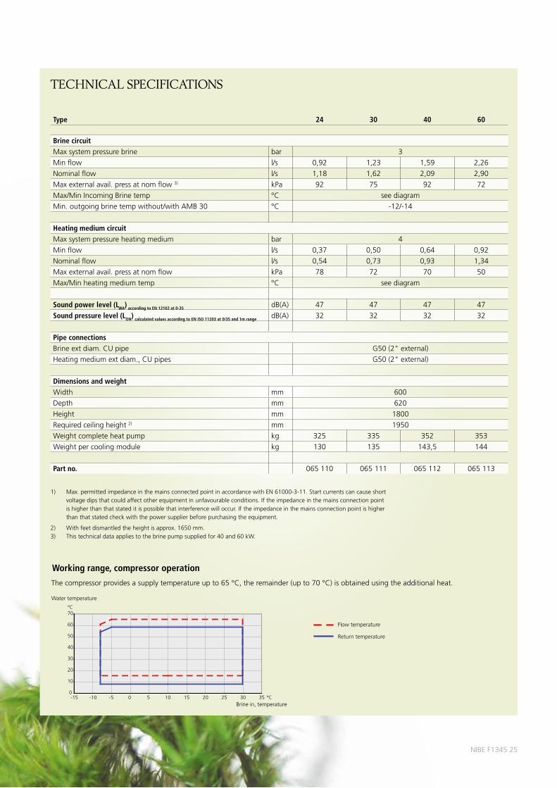
Working range, compressor operation
Thecompressorprovidesasupplytemperatureupto65°C,theremainder(upto70°C)isobtainedusingtheadditionalheat.
0
10
20
30
40
50
60
70
-15 -10 -5 0 5 10 15 20 25 30 35
°CVattentemperatur
°CKöldbärare in, temperatur
Framledning
Returledning
0
10
20
30
40
50
60
70
-15 -10 -5 0 5 10 15 20 25 30 35
°CVattentemperatur
°CKöldbärare in, temperatur
Framledning
Returledning
Watertemperature
Brinein,temperature
Flowtemperature
Returntemperature
technical speciFications

Outdoorsensor Insulationtape
Non-returnvalves(4xG2,internalthread)
Temperaturesensor(5x)
Installer manual
LEK
NIBE™ F1345Ground source heat pump
IHB GB 1210-2031837
O-rings
Installermanual
Operating manual
LEK
NIBE™ F1345Ground source heat pump
OHB GB 1210-2031838
Externalbrinepump(for40and60kWonly)
Usermanual
Currentsensor(Innerdiameter11.8mm),not60kW
HeatingpipepasteAluminiumtape
Theenclosedkitislocatedonthepackagingfortheheatpump.
Safetyvalve(3bar)
Particlefilter24-40kW:2pcsG11/4(internalthread),2pcsG11/2(internalthread)60kW:2pcsG11/4(internalthread),2pcsG2(internalthread)
LEK
LEK
LEK
LEK
LEK
LEK
LE
K
LE
K
LE
K
LE
K
Cabletie
HR 10Auxiliary relay
Partno.089423
AMB 30Air module, collector
Partno.065046
MODBUS 40Communications moduleMODBUS40enablesF1345tobecontrolledandmonitoredinaBMSsystem.CommunicationoccursusingMODBUS-RTU.
Partno.067144
SMS 40Communications module SMS40enablesoperationandmonitoringviaaGSMmodule,us-ingamobilephoneviaSMSmes-sages.IfthemobiletelephonehastheAndroidoperatingsystemthe”NIBEMobileApp”canbeused.
Partno.067073
LEK
accessories
ECS 40/ECS 41Extra shunt group ThisaccessoryisusedwhenF1345isinstalledinhouseswithtwoormoredifferentclimatesystemsthatrequiredifferentsupplytemperatures.ECS40 Partno.067061(max80m²)ECS41 Partno.067099(min80m²)
FLMExhaust air moduleFLMisanexhaustairmodulespeciallydesignedtocombinerecoveryofmechanicalexhaustairwithanenergycollectorinrock.
FLM Partno.067011Bracketpack Partno.067083
LEK
ACS 45 Active/Passive cooling (4-pipe)
Partno.067195
ELKExternal electrical additionTheseaccessoriesmayrequireaccessoriescardAXC50.
ELK213 Partno.069500ELK15 Partno.069022ELK26 Partno.067074ELK42 Partno.067075
LEK
LEK
LEK
LEK
LE
K
GR
UN
DFO
STyp
eU
PS
25
- 6
01
30
P/N
:59
52
644
723
0V
-
HE
JSA
N
PC
;00
17
NIB
DK
50
Hz
IP
44
TF
1
10
Cla
ss H
Ma
x. 1
0ba
r
2.5
uF
45
0.2
06
50
.30
90
0.4
0
1m(A
)P,
(W)
LEK
LEK
LEK
LE
K
LEK
LEK
26NIBEF1345
supplied components

LEK
RMU 40Room unitRMU40meansthatcontrolandmonitoringoftheheatpumpcanbecarriedoutinadifferentpartoftheaccommodationtowhereF1345islocated.
Partno.067064
SOLAR 42Solar pack Solar42meansthatF1345canbeconnectedtosolarheating.
Partno.067084
LEK
LEK
KB R32Filling valve kitFillingvalvekitforfillingbrineinthecollectorhoseforrockheatpumps.Includesdirtfilterandinsulation.
Partno.089971
LEK
LEK
AXC 50Accessory cardAnaccessorycardisrequiredifstepcontrolledadditionalheat(e.g.externalelectricboiler)orifshuntcontrolledadditionalheat(e.g.wood/oil/gas/pelletboiler),passive/activecooling2pipe,passivecooling2respectively4pipesorifhotwatercomfortistobeconnectedtoF1345.
Partno.067193
UKV Neutralization vesselUKV200 Partno.080300UKV300 Partno.080301UKV500 Partno.080302
VPAHot water heaterVPA300/200CU Partno.088710VPA300/200E Partno.088700VPA450/300CU Partno.088660VPA450/300E Partno.088670VPAS300/450CUPartno.087720VPAS300/450E Partno.087710
LE
K
LE
K
LE
K
LEK
LE
K
LE
K
LEK
VPBHot water heater
Waterheaterwithchargecoil.
VPB500 Partno.083220VPB750 Partno.083230VPB1000 Partno.083240
VST 20Hot water controlReversingvalve,Cu-pipeØ35(Maxrecommendedpower,40°kW)
Partno.089388
Immersion heater IU3kW Partno.69520306kW Partno.69520719kW Partno.6952097
K11 Connection boxConnectionboxwiththermostatandoverheatingprotection.
Partno.018893
LEK
LEK
LEK
LEK
LEK
LEK
K13
LEK
K11
K10
accessories
POOL 40Pool heatingPOOL40isanaccessorythatenablespoolheatingwithF1345.(max17kW)
Partno.067062
HPAC 42
Active/Passive cooling (2-pipe)HPACcombinedwithaheatpumpisaclimatecontrolsystemforheatingandcoolinghousesandapartmentbuildings.(Max40kW)
Partno.067025

MILJÖMÄRKT
307–005
ThisbrochureisapublicationfromNIBE.Allproductillustrations,factsandspecificationsarebasedoncurrentinformationatthetimeofthepublication’sapproval.NIBEmakesreservationsforanyfactualorprintingerrorsinthisbrochure.Photos:www.benfoto.se.©NIBE 2012.
NIBEisISO-certified:SS-ENISO9001:2000SS-ENISO14001:2004 NIBEEnergySystemsAB
Box1428521MarkarydSWEDENTel.+46433-73000www.nibe.eu 63
9502
Tec
hnic
alP
BDG
BN
IBE
F134
512
22-1