nfpa - 2012 fall revision cycle report on proposals · nfpa documents, check the nfpa website () or...
TRANSCRIPT

Report onProposals
2012 Fall Revision Cycle
NOTE: The proposed NFPA documents addressed in this Report on
Proposals (ROP) and in a follow-up Report on Comments (ROC) will only
be presented for action at the NFPA June 2013 Association Technical
Meeting to be held June 10–13, 2013, at the McCormick Place Convention
Center, Chicago, IL, when proper Amending Motions have been submitted
to the NFPA by the deadline of October 5, 2012. Documents that receive
no motions will not be presented at the meeting and instead will be
forwarded directly to the Standards Council for action on issuance. For more
information on the rules and for up-to-date information on schedules and
deadlines for processing NFPA documents, check the NFPA website (www.
nfpa.org) or contact NFPA Standards Administration.
ISSN 1079-5332 Copyright © 2012 All Rights Reserved
NFPA and National Fire Protection Association are registered trademarks of the National Fire Protection Association, Quincy, MA 02169.
National Fire Protection Association®1 BATTERYMARCH PARK, QUINCY, MA 02169-7471
A compilation of NFPA® TechnicalCommittee Reports on Proposals for public review and comment
Public Comment Deadline: March 2, 2012

Information on NFPA Codes and Standards Development
I. Applicable Regulations. The primary rules governing the processing of NFPA documents (codes, standards, recommended practices, and guides) are the NFPA Regulations Governing Committee Projects (Regs). Other applicable rules include NFPA Bylaws, NFPA Technical Meeting Convention Rules, NFPA Guide for the Conduct of Participants in the NFPA Standards Development Process, and the NFPA Regulations Governing Petitions to the Board of Directors from Decisions of the Standards Council. Most of these rules and regulations are contained in the NFPA Directory. For copies of the Directory, contact Codes and Standards Administration at NFPA Headquarters; all these documents are also available on the NFPA website at “www.nfpa.org.”
The following is general information on the NFPA process. All participants, however, should refer to the actual rules and regulations for a full understanding of this process and for the criteria that govern participation.
II. Technical Committee Report. The Technical Committee Report is defined as “the Report of the Technical Committee and Technical Correlating Committee (if any) on a document. A Technical Committee Report consists of the Report on Proposals (ROP), as modified by the Report on Comments (ROC), published by the Association.”
III. Step 1: Report on Proposals (ROP). The ROP is defined as “a report to the Association on the actions taken by Technical Committees and/or Technical Correlating Committees, accompanied by a ballot statement and one or more proposals on text for a new document or to amend an existing document.” Any objection to an action in the ROP must be raised through the filing of an appropriate Comment for consideration in the ROC or the objection will be considered resolved.
IV. Step 2: Report on Comments (ROC). The ROC is defined as “a report to the Association on the actions taken by Technical Committees and/or Technical Correlating Committees accompanied by a ballot statement and one or more comments resulting from public review of the Report on Proposals (ROP).” The ROP and the ROC together constitute the Technical Committee Report. Any outstanding objection following the ROC must be raised through an appropriate Amending Motion at the Association Technical Meeting or the objection will be considered resolved.
V. Step 3a: Action at Association Technical Meeting. Following the publication of the ROC, there is a period during which those wishing to make proper Amending Motions on the Technical Committee Reports must signal their intention by submitting a Notice of Intent to Make a Motion. Documents that receive notice of proper Amending Motions (Certified Amending Motions) will be presented for action at the annual June Association Technical Meeting. At the meeting, the NFPA membership can consider and act on these Certified Amending Motions as well as Follow-up Amending Motions, that is, motions that become necessary as a result of a previous successful Amending Motion. (See 4.6.2 through 4.6.9 of Regs for a summary of the available Amending Motions and who may make them.) Any outstanding objection following action at an Association Technical Meeting (and any further Technical Committee consideration following successful Amending Motions, see Regs at 4.7) must be raised through an appeal to the Standards Council or it will be considered to be resolved.
VI. Step 3b: Documents Forwarded Directly to the Council. Where no Notice of Intent to Make a Motion (NITMAM) is received and certified in accordance with the Technical Meeting Convention Rules, the document is forwarded directly to the Standards Council for action on issuance. Objections are deemed to be resolved for these documents.
VII. Step 4a: Council Appeals. Anyone can appeal to the Standards Council concerning procedural or substantive matters related to the development, content, or issuance of any document of the Association or on matters within the purview of the authority of the Council, as established by the Bylaws and as determined by the Board of Directors. Such appeals must be in written form and filed with the Secretary of the Standards Council (see 1.6 of Regs). Time constraints for filing an appeal must be in accordance with 1.6.2 of the Regs. Objections are deemed to be resolved if not pursued at this level.
VIII. Step 4b: Document Issuance. The Standards Council is the issuer of all documents (see Article 8 of Bylaws). The Council acts on the issuance of a document presented for action at an Association Technical Meeting within 75 days from the date of the recommendation from the Association Technical Meeting, unless this period is extended by the Council (see 4.8 of Regs). For documents forwarded directly to the Standards Council, the Council acts on the issuance of the document at its next scheduled meeting, or at such other meeting as the Council may determine (see 4.5.6 and 4.8 of Regs).
IX. Petitions to the Board of Directors. The Standards Council has been delegated the responsibility for the administration of the codes and standards development process and the issuance of documents. However, where extraordinary circumstances requiring the intervention of the Board of Directors exist, the Board of Directors may take any action necessary to fulfill its obligations to preserve the integrity of the codes and standards development process and to protect the interests of the Association. The rules for petitioning the Board of Directors can be found in the Regulations Governing Petitions to the Board of Directors from Decisions of the Standards Council and in 1.7 of the Regs.
X. For More Information. The program for the Association Technical Meeting (as well as the NFPA website as information becomes available) should be consulted for the date on which each report scheduled for consideration at the meeting will be presented. For copies of the ROP and ROC as well as more information on NFPA rules and for up-to-date information on schedules and deadlines for processing NFPA documents, check the NFPA website (www.nfpa.org) or contact NFPA Codes & Standards Administration at (617) 984-7246.

i
2012 Fall Revision Cycle ROP Contents
by NFPA Numerical Designation
Note: Documents appear in numerical order.
NFPA No. Type Action Title Page No.
10 P Standard for Portable Fire Extinguishers ........................................................................................................ 10-1 14 P Standard for the Installation of Standpipe and Hose Systems ........................................................................ 14-1 17 P Standard for Dry Chemical Extinguishing Systems ....................................................................................... 17-1 17A P Standard for Wet Chemical Extinguishing Systems .................................................................................... 17A-1 22 P Standard for Water Tanks for Private Fire Protection .................................................................................... 22-1 36 P Standard for Solvent Extraction Plants ........................................................................................................... 36-1 52 P Vehicular Gaseous Fuel Systems Code .......................................................................................................... 52-1 67 N Guideline on Explosion Protection for Gaseous Mixtures in Pipe Systems .................................................. 67-1 68 P Standard on Explosion Protection by Deflagration Venting .......................................................................... 68-1 70B P Recommended Practice for Electrical Equipment Maintenance ................................................................. 70B-1 140 P Standard on Motion Picture and Television Production Studio Soundstages, Approved Production Facilities, and Production Locations ........................................................................ 140-1 211 P Standard for Chimneys, Fireplaces, Vents, and Solid Fuel–Burning Appliances ........................................ 211-1 225 P Model Manufactured Home Installation Standard ....................................................................................... 225-1 241 P Standard for Safeguarding Construction, Alteration, and Demolition Operations ...................................... 241-1 259 P Standard Test Method for Potential Heat of Building Materials .................................................................. 259-1 260 P Standard Methods of Tests and Classification System for Cigarette Ignition Resistance of Components of Upholstered Furniture ..................................................................................................... 260-1 261 P Standard Method of Test for Determining Resistance of Mock-Up Upholstered Furniture Material Assemblies to Ignition by Smoldering Cigarettes.......................................................... 261-1 270 P Standard Test Method for Measurement of Smoke Obscuration Using a Conical Radiant Source in a Single Closed Chamber .............................................................................................................. 270-1 274 P Standard Test Method to Evaluate Fire Performance Characteristics of Pipe Insulation ............................ 274-1
289 P Standard Method of Fire Test for Individual Fuel Packages ........................................................................ 289-1 290 P Standard for Fire Testing of Passive Protection Materials for Use on LP-Gas Containers ......................... 290-1 495 P Explosive Materials Code ............................................................................................................................. 495-1 496 P Standard for Purged and Pressurized Enclosures for Electrical Equipment ............................................... 496-1 498 P Standard for Safe Havens and Interchange Lots for Vehicles Transporting Explosives ............................. 498-1 501 P Standard on Manufactured Housing ............................................................................................................. 501-1 501A P Standard for Fire Safety Criteria for Manufactured Home Installations, Sites, and Communities .......... 501A-1 505 P Fire Safety Standard for Powered Industrial Trucks Including Type Designations, Areas of Use, Conversions, Maintenance, and Operations ................................................................................................. 505-1 551 P Guide for the Evaluation of Fire Risk Assessments ..................................................................................... 551-1
705 P Recommended Practice for a Field Flame Test for Textiles and Films ....................................................... 705-1
ii
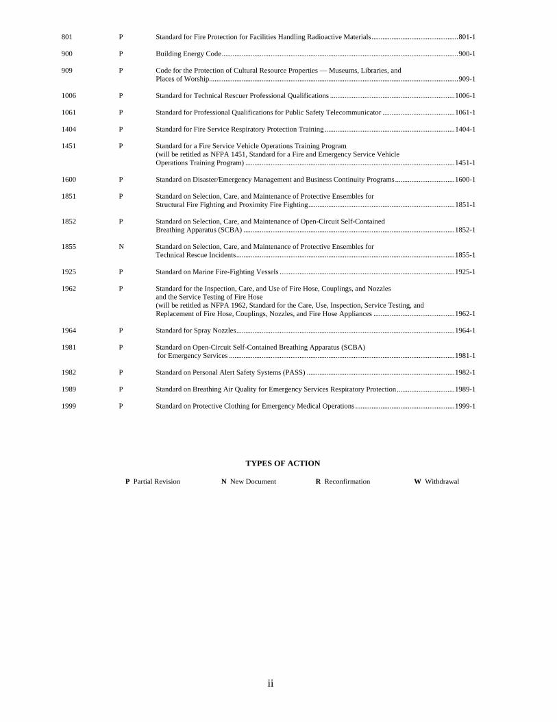
801 P Standard for Fire Protection for Facilities Handling Radioactive Materials ................................................ 801-1 900 P Building Energy Code ................................................................................................................................... 900-1
909 P Code for the Protection of Cultural Resource Properties — Museums, Libraries, and Places of Worship.......................................................................................................................................... 909-1 1006 P Standard for Technical Rescuer Professional Qualifications ..................................................................... 1006-1 1061 P Standard for Professional Qualifications for Public Safety Telecommunicator ........................................ 1061-1 1404 P Standard for Fire Service Respiratory Protection Training ........................................................................ 1404-1 1451 P Standard for a Fire Service Vehicle Operations Training Program (will be retitled as NFPA 1451, Standard for a Fire and Emergency Service Vehicle Operations Training Program) .................................................................................................................... 1451-1 1600 P Standard on Disaster/Emergency Management and Business Continuity Programs ................................. 1600-1 1851 P Standard on Selection, Care, and Maintenance of Protective Ensembles for Structural Fire Fighting and Proximity Fire Fighting ................................................................................. 1851-1 1852 P Standard on Selection, Care, and Maintenance of Open-Circuit Self-Contained Breathing Apparatus (SCBA) ..................................................................................................................... 1852-1 1855 N Standard on Selection, Care, and Maintenance of Protective Ensembles for Technical Rescue Incidents ......................................................................................................................... 1855-1 1925 P Standard on Marine Fire-Fighting Vessels ................................................................................................. 1925-1 1962 P Standard for the Inspection, Care, and Use of Fire Hose, Couplings, and Nozzles and the Service Testing of Fire Hose (will be retitled as NFPA 1962, Standard for the Care, Use, Inspection, Service Testing, and Replacement of Fire Hose, Couplings, Nozzles, and Fire Hose Appliances ............................................. 1962-1 1964 P Standard for Spray Nozzles ......................................................................................................................... 1964-1 1981 P Standard on Open-Circuit Self-Contained Breathing Apparatus (SCBA) for Emergency Services ............................................................................................................................. 1981-1 1982 P Standard on Personal Alert Safety Systems (PASS) .................................................................................. 1982-1 1989 P Standard on Breathing Air Quality for Emergency Services Respiratory Protection ................................ 1989-1 1999 P Standard on Protective Clothing for Emergency Medical Operations ....................................................... 1999-1
TYPES OF ACTION
P Partial Revision N New Document R Reconfirmation W Withdrawal

iii
2012 Fall Revision Cycle ROP Committees Reporting
Type Action Page No. Building Code Building Systems 900 Building Energy Code P 900-1 Chimneys, Fireplaces, and Venting Systems for Heat-Producing Appliances 211 Standard for Chimneys, Fireplaces, Vents, and Solid Fuel–Burning Appliances P 211-1 Construction and Demolition 241 Standard for Safeguarding Construction, Alteration, and Demolition Operations P 241-1 Cultural Resources 909 Code for the Protection of Cultural Resource Properites — Museums, Libraries, and Places of
Worship P 909-1
Dry and Wet Chemical Extinguishing Systems 17 Standard for Dry Chemical Extinguishing Systems P 17-1 17A Standard for Wet Chemical Extinguishing Systems P 17A-1 Electrical Equipment in Chemical Atmospheres 496 Standard for Purged and Pressurized Enclosures for Electrical Equipment P 496-1 National Electrical Code Electrical Equipment Maintenance 70B Recommended Practice for Electrical Equipment Maintenance P 70B-1 Emergency Management and Business Continuity 1600 Standard on Disaster/Emergency Management and Business Continuity Programs P 1600-1 Explosion Protection Systems 67 Guideline on Explosion Protection for Gaseous Mixtures in Pipe Systems N 67-1 68 Standard on Explosion Protection by Deflagration Venting P 68-1 Explosives 495 Explosive Materials Code P 495-1 498 Standard for Safe Havens and Interchange Lots for Vehicles Transporting Explosives P 498-1 Fire and Emergency Services Protective Clothing and Equipment Electronic Safety Equipment 1982 Standard on Personal Alert Safety Systems (PASS) P 1982-1 Emergency Medical Services Protective Clothing and Equipment 1999 Standard on Protective Clothing for Emergency Medical Operations P 1999-1 Respiratory Protection Equipment 1852 Standard on Selection, Care, and Maintenance of Open-Circuit Self-Contained Breathing Apparatus
(SCBA) P 1852-1
1981 Standard on Open-Circuit Self-Contained Breathing Apparatus (SCBA) for Emergency Services P 1981-1 1989 Standard on Breathing Air Quality for Emergency Services Respiratory Protection P 1989-1 Special Operations Protective Clothing and Equipment 1855 Standard on Selection, Care, and Maintenance of Protective Ensembles for Technical Rescue Incidents
N 1855-1
Structural and Proximity Fire Fighting Protective Clothing and Equipment 1851 Standard for Selection, Care, and Maintenance of Protective Ensembles for Structural Fire Fighting
and Proximity Fire Fighting P 1851-1
Fire Hose 1962 Standard for the Inspection, Care, and Use of Fire Hose, Couplings, and Nozzles and the Service
Testing of Fire Hose P 1962-1
1964 Standard for Spray Nozzles P 1964-1 Fire Protection for Nuclear Facilities 801 Standard for Fire Protection for Facilities Handling Radioactive Materials P 801-1 Fire Risk Assessment Methods 551 Guide for the Evaluation of Fire Risk Assessments P 551-1

iv
Fire Service Training 1404 Standard for Fire Service Respiratory Protection Training P 1404-1 1451 Standard for a Fire Service Vehicle Operations Training Program P 1451-1 Fire Tests 259 Standard Test Method for Potential Heat of Building Materials P 259-1 260 Standard Methods of Tests and Classification System for Cigarette Ignition Resistance of
Components of Upholstered Furniture P 260-1
261 Standard Method of Test for Determining Resistance of Mock-Up Upholstered Furniture Material Assemblies to Ignition by Smoldering Cigarettes
P 261-1
270 Standard Test Method for Measurement of Smoke Obscuration Using a Conical Radiant Source in a Single Closed Chamber
P 270-1
274 Standard Test Method to Evaluate Fire Performance Characteristics of Pipe Insulation P 274-1 289 Standard Method of Fire Test for Individual Fuel Packages P 289-1 290 Standard for Fire Testing of Passive Protection Materials for Use on LP-Gas Containers P 290-1 705 Recommended Practice for a Field Flame Test for Textiles and Films P 705-1 Industrial Trucks 505 Fire Safety Standard for Powered Industrial Trucks Including Type Designations, Areas of Use,
Conversions, Maintenance, and Operations P 505-1
Manufactured Housing 225 Model Manufactured Home Installation Standard P 225-1 501 Standard on Manufactured Housing P 501-1 501A Standard for Fire Safety Criteria for Manufactured Home Installations, Sites, and Communities P 501A-1 Marine Fire Fighting Vessels 1925 Standard on Marine Fire-Fighting Vessels P 1925-1 Motion Picture and Television Industry 140 Standard on Motion Picture and Television Production Studio Soundstages, Approved Production
Facilities, and Production Locations P 140-1
Portable Fire Extinguishers 10 Standard for Portable Fire Extinguishers P 10-1 Professional Qualifications Rescue Technician Professional Qualifications 1006 Standard for Technical Rescuer Professional Qualifications P 1006-1 Public Safety Telecommunicator Professional Qualifications 1061 Standard for Professional Qualifications for Public Safety Telecommunicator P 1061-1 Solvent Extraction Plants 36 Standard for Solvent Extraction Plants P 36-1 Standpipes 14 Standard for the Installation of Standpipe and Hose Systems P 14-1 Vehicular Alternative Fuel Systems 52 Vehicular Gaseous Fuel Systems Code P 52-1 Water Tanks 22 Standard for Water Tanks for Private Fire Protection P 22-1
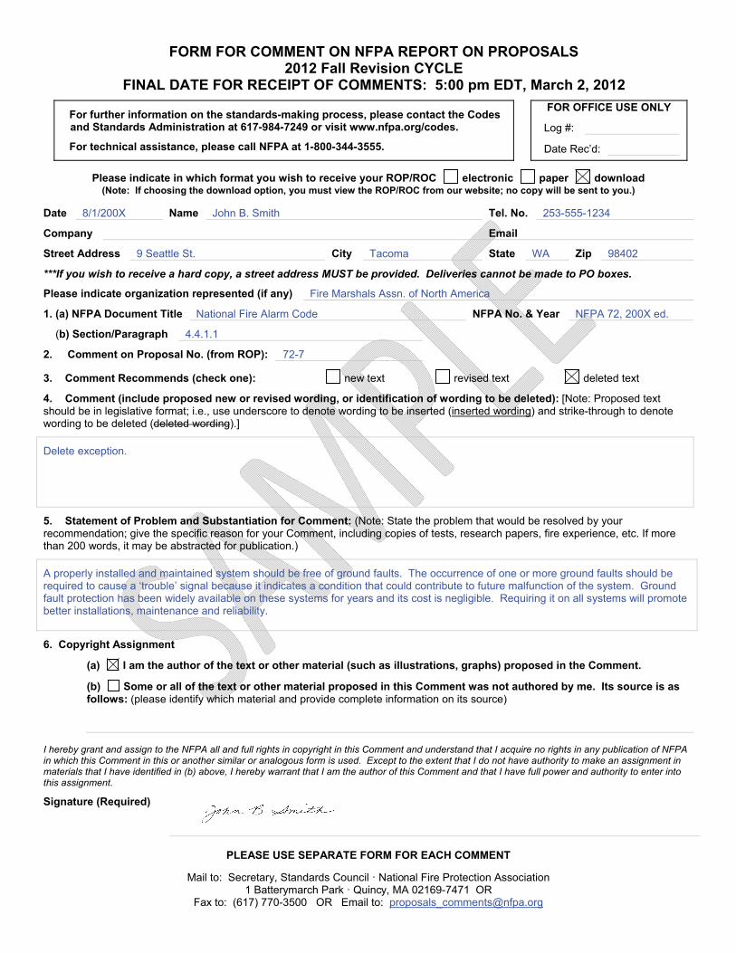
FORM FOR COMMENT ON NFPA REPORT ON PROPOSALS 2012 Fall Revision CYCLE
FINAL DATE FOR RECEIPT OF COMMENTS: 5:00 pm EDT, March 2, 2012
For further information on the standards-making process, please contact the Codes and Standards Administration at 617-984-7249 or visit www.nfpa.org/codes.
For technical assistance, please call NFPA at 1-800-344-3555.
FOR OFFICE USE ONLY
Log #:
Date Rec’d:
Please indicate in which format you wish to receive your ROP/ROC electronic paper download (Note: If choosing the download option, you must view the ROP/ROC from our website; no copy will be sent to you.)
Date 8/1/200X Name John B. Smith Tel. No. 253-555-1234
Company Email
Street Address 9 Seattle St. City Tacoma State WA Zip 98402
***If you wish to receive a hard copy, a street address MUST be provided. Deliveries cannot be made to PO boxes.
Please indicate organization represented (if any) Fire Marshals Assn. of North America
1. (a) NFPA Document Title National Fire Alarm Code NFPA No. & Year NFPA 72, 200X ed.
(b) Section/Paragraph 4.4.1.1
2. Comment on Proposal No. (from ROP): 72-7
3. Comment Recommends (check one): new text revised text deleted text
4. Comment (include proposed new or revised wording, or identification of wording to be deleted): [Note: Proposed text should be in legislative format; i.e., use underscore to denote wording to be inserted (inserted wording) and strike-through to denote wording to be deleted (deleted wording).]
Delete exception.
5. Statement of Problem and Substantiation for Comment: (Note: State the problem that would be resolved by your recommendation; give the specific reason for your Comment, including copies of tests, research papers, fire experience, etc. If more than 200 words, it may be abstracted for publication.)
A properly installed and maintained system should be free of ground faults. The occurrence of one or more ground faults should be required to cause a ‘trouble’ signal because it indicates a condition that could contribute to future malfunction of the system. Ground fault protection has been widely available on these systems for years and its cost is negligible. Requiring it on all systems will promote better installations, maintenance and reliability.
6. Copyright Assignment
(a) I am the author of the text or other material (such as illustrations, graphs) proposed in the Comment.
(b) Some or all of the text or other material proposed in this Comment was not authored by me. Its source is as follows: (please identify which material and provide complete information on its source)
I hereby grant and assign to the NFPA all and full rights in copyright in this Comment and understand that I acquire no rights in any publication of NFPA in which this Comment in this or another similar or analogous form is used. Except to the extent that I do not have authority to make an assignment in materials that I have identified in (b) above, I hereby warrant that I am the author of this Comment and that I have full power and authority to enter into this assignment.
Signature (Required)
PLEASE USE SEPARATE FORM FOR EACH COMMENT
Mail to: Secretary, Standards Council · National Fire Protection Association 1 Batterymarch Park · Quincy, MA 02169-7471 OR
Fax to: (617) 770-3500 OR Email to: [email protected]

11/17/2011

FORM FOR COMMENT ON NFPA REPORT ON PROPOSALS 2012 Fall Revision CYCLE
FINAL DATE FOR RECEIPT OF COMMENTS: 5:00 pm EDT, March 2, 2012
For further information on the standards-making process, please contact the Codes and Standards Administration at 617-984-7249 or visit www.nfpa.org/codes.
For technical assistance, please call NFPA at 1-800-344-3555.
FOR OFFICE USE ONLY
Log #:
Date Rec’d:
Please indicate in which format you wish to receive your ROP/ROC electronic paper download (Note: If choosing the download option, you must view the ROP/ROC from our website; no copy will be sent to you.)
Date Name Tel. No.
Company Email
Street Address City State Zip
***If you wish to receive a hard copy, a street address MUST be provided. Deliveries cannot be made to PO boxes.
Please indicate organization represented (if any)
1. (a) NFPA Document Title NFPA No. & Year
(b) Section/Paragraph
2. Comment on Proposal No. (from ROP):
3. Comment Recommends (check one): new text revised text deleted text
4. Comment (include proposed new or revised wording, or identification of wording to be deleted): [Note: Proposed text should be in legislative format; i.e., use underscore to denote wording to be inserted (inserted wording) and strike-through to denote wording to be deleted (deleted wording).]
5. Statement of Problem and Substantiation for Comment: (Note: State the problem that would be resolved by your recommendation; give the specific reason for your Comment, including copies of tests, research papers, fire experience, etc. If more than 200 words, it may be abstracted for publication.)
6. Copyright Assignment
(a) I am the author of the text or other material (such as illustrations, graphs) proposed in the Comment.
(b) Some or all of the text or other material proposed in this Comment was not authored by me. Its source is as follows: (please identify which material and provide complete information on its source)
I hereby grant and assign to the NFPA all and full rights in copyright in this Comment and understand that I acquire no rights in any publication of NFPA in which this Comment in this or another similar or analogous form is used. Except to the extent that I do not have authority to make an assignment in materials that I have identified in (b) above, I hereby warrant that I am the author of this Comment and that I have full power and authority to enter into this assignment.
Signature (Required)
PLEASE USE SEPARATE FORM FOR EACH COMMENT
Mail to: Secretary, Standards Council · National Fire Protection Association 1 Batterymarch Park · Quincy, MA 02169-7471 OR
Fax to: (617) 770-3500 OR Email to: [email protected] 11/17/2011
v
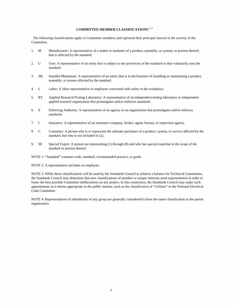
COMMITTEE MEMBER CLASSIFICATIONS1,2,3,4
The following classifications apply to Committee members and represent their principal interest in the activity of the Committee. 1. M Manufacturer: A representative of a maker or marketer of a product, assembly, or system, or portion thereof,
that is affected by the standard. 2. U User: A representative of an entity that is subject to the provisions of the standard or that voluntarily uses the
standard. 3. IM Installer/Maintainer: A representative of an entity that is in the business of installing or maintaining a product,
assembly, or system affected by the standard. 4. L Labor: A labor representative or employee concerned with safety in the workplace. 5. RT Applied Research/Testing Laboratory: A representative of an independent testing laboratory or independent
applied research organization that promulgates and/or enforces standards. 6. E Enforcing Authority: A representative of an agency or an organization that promulgates and/or enforces
standards. 7. I Insurance: A representative of an insurance company, broker, agent, bureau, or inspection agency. 8. C Consumer: A person who is or represents the ultimate purchaser of a product, system, or service affected by the
standard, but who is not included in (2). 9. SE Special Expert: A person not representing (1) through (8) and who has special expertise in the scope of the
standard or portion thereof. NOTE 1: “Standard” connotes code, standard, recommended practice, or guide. NOTE 2: A representative includes an employee. NOTE 3: While these classifications will be used by the Standards Council to achieve a balance for Technical Committees, the Standards Council may determine that new classifications of member or unique interests need representation in order to foster the best possible Committee deliberations on any project. In this connection, the Standards Council may make such appointments as it deems appropriate in the public interest, such as the classification of “Utilities” in the National Electrical Code Committee. NOTE 4: Representatives of subsidiaries of any group are generally considered to have the same classification as the parent organization.

Sequence of Events Leading to Issuance of an NFPA Committee Document
Step 1 Call for Proposals
▼ Proposed new document or new edition of an existing document is entered into one of two yearly revision cycles, and a Call for Proposals is published.
Step 2 Report on Proposals (ROP)
▼ Committee meets to act on Proposals, to develop its own Proposals, and to prepare its Report.
▼ Committee votes by written ballot on Proposals. If two-thirds approve, Report goes forward. Lacking two-thirds approval, Report returns to Committee.
▼ Report on Proposals (ROP) is published for public review and comment.
Step 3 Report on Comments (ROC)
▼ Committee meets to act on Public Comments to develop its own Comments, and to prepare its report.
▼ Committee votes by written ballot on Comments. If two-thirds approve, Report goes forward. Lacking two-thirds approval, Report returns to Committee.
▼ Report on Comments (ROC) is published for public review.
Step 4 Association Technical Meeting
▼ “Notices of intent to make a motion” are filed, are reviewed, and valid motions are certified for presentation at the Association Technical Meeting. (“Consent Documents” that have no certified motions bypass the Association Technical Meeting and proceed to the Standards Council for issuance.)
▼ NFPA membership meets each June at the Association Technical Meeting and acts on Technical Committee Reports (ROP and ROC) for documents with “certified amending motions.”
▼ Committee(s) vote on any amendments to Report approved at NFPA Annual Membership Meeting.
Step 5 Standards Council Issuance
▼ Notification of intent to file an appeal to the Standards Council on Association action must be filed within 20 days of the NFPA Annual Membership Meeting.
▼ Standards Council decides, based on all evidence, whether or not to issue document or to take other action, including hearing any appeals.
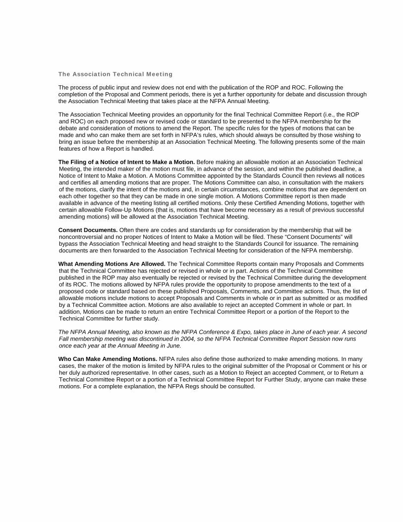
The Association Technical Meeting
The process of public input and review does not end with the publication of the ROP and ROC. Following the completion of the Proposal and Comment periods, there is yet a further opportunity for debate and discussion through the Association Technical Meeting that takes place at the NFPA Annual Meeting.
The Association Technical Meeting provides an opportunity for the final Technical Committee Report (i.e., the ROP and ROC) on each proposed new or revised code or standard to be presented to the NFPA membership for the debate and consideration of motions to amend the Report. The specific rules for the types of motions that can be made and who can make them are set forth in NFPA’s rules, which should always be consulted by those wishing to bring an issue before the membership at an Association Technical Meeting. The following presents some of the main features of how a Report is handled.
The Filing of a Notice of Intent to Make a Motion. Before making an allowable motion at an Association Technical Meeting, the intended maker of the motion must file, in advance of the session, and within the published deadline, a Notice of Intent to Make a Motion. A Motions Committee appointed by the Standards Council then reviews all notices and certifies all amending motions that are proper. The Motions Committee can also, in consultation with the makers of the motions, clarify the intent of the motions and, in certain circumstances, combine motions that are dependent on each other together so that they can be made in one single motion. A Motions Committee report is then made available in advance of the meeting listing all certified motions. Only these Certified Amending Motions, together with certain allowable Follow-Up Motions (that is, motions that have become necessary as a result of previous successful amending motions) will be allowed at the Association Technical Meeting.
Consent Documents. Often there are codes and standards up for consideration by the membership that will be noncontroversial and no proper Notices of Intent to Make a Motion will be filed. These “Consent Documents” will bypass the Association Technical Meeting and head straight to the Standards Council for issuance. The remaining documents are then forwarded to the Association Technical Meeting for consideration of the NFPA membership.
What Amending Motions Are Allowed. The Technical Committee Reports contain many Proposals and Comments that the Technical Committee has rejected or revised in whole or in part. Actions of the Technical Committee published in the ROP may also eventually be rejected or revised by the Technical Committee during the development of its ROC. The motions allowed by NFPA rules provide the opportunity to propose amendments to the text of a proposed code or standard based on these published Proposals, Comments, and Committee actions. Thus, the list of allowable motions include motions to accept Proposals and Comments in whole or in part as submitted or as modified by a Technical Committee action. Motions are also available to reject an accepted Comment in whole or part. In addition, Motions can be made to return an entire Technical Committee Report or a portion of the Report to the Technical Committee for further study.
The NFPA Annual Meeting, also known as the NFPA Conference & Expo, takes place in June of each year. A second Fall membership meeting was discontinued in 2004, so the NFPA Technical Committee Report Session now runs once each year at the Annual Meeting in June.
Who Can Make Amending Motions. NFPA rules also define those authorized to make amending motions. In many cases, the maker of the motion is limited by NFPA rules to the original submitter of the Proposal or Comment or his or her duly authorized representative. In other cases, such as a Motion to Reject an accepted Comment, or to Return a Technical Committee Report or a portion of a Technical Committee Report for Further Study, anyone can make these motions. For a complete explanation, the NFPA Regs should be consulted.
Action on Motions at the Association Technical Meeting. In order to actually make a Certified Amending Motion at the Association Technical Meeting, the maker of the motion must sign in at least an hour before the session begins. In this way a final list of motions can be set in advance of the session. At the session, each proposed document up for consideration is presented by a motion to adopt the Technical Committee Report on the document. Following each such motion, the presiding officer in charge of the session opens the floor to motions on the document from the final list of Certified Amending Motions followed by any permissible Follow-Up Motions. Debate and voting on each motion proceeds in accordance with NFPA rules. NFPA membership is not required in order to make or speak to a motion, but voting is limited to NFPA members who have joined at least 180 days prior to the Association Technical Meeting and have registered for the meeting. At the close of debate on each motion, voting takes place, and the motion requires a majority vote to carry. In order to amend a Technical Committee Report, successful amending motions must be confirmed by the responsible Technical Committee, which conducts a written ballot on all successful amending motions following the meeting and prior to the document being forwarded to the Standards Council for issuance.
Standards Council Issuance
One of the primary responsibilities of the NFPA Standards Council, as the overseer of the NFPA codes and standards development process, is to act as the official issuer of all NFPA codes and standards. When it convenes to issue NFPA documents, it also hears any appeals related to the document. Appeals are an important part of assuring that all NFPA rules have been followed and that due process and fairness have been upheld throughout the codes and standards development process. The Council considers appeals both in writing and through the conduct of hearings at which all interested parties can participate. It decides appeals based on the entire record of the process as well as all submissions on the appeal. After deciding all appeals related to a document before it, the Council, if appropriate, proceeds to issue the document as an official NFPA code or standard. Subject only to limited review by the NFPA Board of Directors, the decision of the Standards Council is final, and the new NFPA code or standard becomes effective twenty days after Standards Council issuance.

22-1
Report on Proposals F2012 — Copyright, NFPA NFPA 22 Report of the Committee on
Water Tanks
Robert M. Gagnon, ChairGagnon Engineering, MD [SE]
Phillip A. Brown, SecretaryAmerican Fire Sprinkler Association, Inc., TX [IM]
Babanna Biradar, Bechtel Corporation, TX [SE] John D. Campbell, Telgian Corporation, MO [SE] John R. Conrady, Wilsonville, AL [SE] Christopher Culp, Fire Dynamics, KS [SE] Sullivan D. Curran, Fiberglass Tank & Pipe Institute, TX [M] Bruce A. Edwards, Liberty Mutual Property, MA [I] Rep. Property Casualty Insurers Association of America Nick Esposito, Tyco/SimplexGrinnell, TX [IM] Rep. National Fire Sprinkler Association Douglas W. Fisher, Fisher Engineering, Inc., GA [SE] Joseph R. Fowler, S.A. Comunale Company, Inc., OH [IM] Daniel M. Fritz, XL Insurance America, Inc., IL [I] Greg Garber, Pittsburg Tank & Tower Inc., VA [M] Chris A. Grooms, State of Alaska Department of Public Safety, AK [E] Jack Hillman, Hall-Woolford Tank Company, Inc., PA [M] David Hochhauser, Isseks Brothers Incorporated, NY [IM] Nicholas A. Legatos, Preload Incorporated, NY [M] Rep. American Concrete Institute Keith McGuire, CST Storage, KS [M] John M. Mitchard, Nuclear Service Organization, DE [I] Bob D. Morgan, Fort Worth Fire Department, TX [E] Bill Mow, Amfuel, AR [M] Andrew Rosenwach, Rosenwach Tank Company, Inc., NY [M] Rep. National Wood Tank Institute Mark A. Sornsin, Ulteig Engineers, Inc., ND [SE] Gregory R. Stein, Tank Industry Consultants, IN [SE]
Alternates
Andrew J. Brady, Nuclear Service Organization, DE [I] (Alt. to John M. Mitchard) Kenneth E. Isman, National Fire Sprinkler Association, Inc., NY [IM] (Alt. to Nick Esposito) Jeremy W. John, Fisher Engineering, Inc., GA [SE] (Alt. to Douglas W. Fisher)Todd M. Kidd, Liberty Mutual Insurance Companies, NC [I] (Alt. to Bruce A. Edwards) Patrick A. McLaughlin, McLaughlin & Associates, RI [M] (Alt. to Sullivan D. Curran) R. Greg Patrick, Treasure Valley Fire Protection, Inc., ID [IM] (Alt. to Phillip A. Brown) John J. Sweeney, Smith Engineered Storage Products Company, IL [M] (Alt. to Keith McGuire)
Staff Liaison: Chad Duffy
Committee Scope: This Committee shall have primary responsibility for documents on the design, construction, installation, and maintenance of tanks and accessory equipment supplying water for fire extinguishment, including gravity and pressure tanks, towers and foundations, pipe connections and fittings, valve enclosures and frost protection, and tank heating equipment.
This list represents the membership at the time the Committee was balloted on the text of this report. Since that time, changes in the membership may have occurred. A key to classifications is found at the front of the document.
The Report of the Technical Committee on Water Tanks is presented for adoption.
This Report was prepared by the Technical Committee on Water Tanks and proposes for adoption, amendments to NFPA 22, Standard for Water Tanks for Private Fire Protection, 2008 edition. NFPA 22-2008 is published in Volume 3 of the 2011 National Fire Codes and in separate pamphlet form.
This Report has been submitted to letter ballot of the Technical Committee on Water Tanks, which consists of 24 voting members. The results of the balloting, after circulation of any negative votes, can be found in the report.
22-2
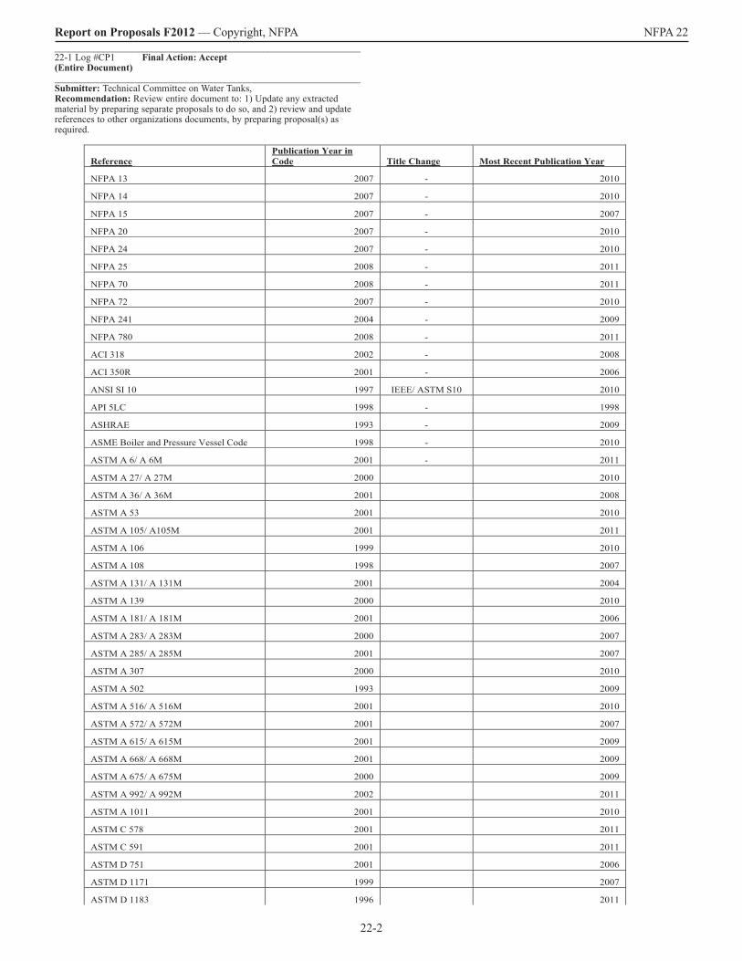
Report on Proposals F2012 — Copyright, NFPA NFPA 22 _______________________________________________________________ 22-1 Log #CP1 Final Action: Accept(Entire Document)_______________________________________________________________ Submitter: Technical Committee on Water Tanks, Recommendation: Review entire document to: 1) Update any extracted material by preparing separate proposals to do so, and 2) review and update references to other organizations documents, by preparing proposal(s) as required.
ReferencePublication Year in Code Title Change Most Recent Publication Year
NFPA 13 2007 - 2010
NFPA 14 2007 - 2010
NFPA 15 2007 - 2007
NFPA 20 2007 - 2010
NFPA 24 2007 - 2010
NFPA 25 2008 - 2011
NFPA 70 2008 - 2011
NFPA 72 2007 - 2010
NFPA 241 2004 - 2009
NFPA 780 2008 - 2011
ACI 318 2002 - 2008
ACI 350R 2001 - 2006
ANSI SI 10 1997 IEEE/ ASTM S10 2010
API 5LC 1998 - 1998
ASHRAE 1993 - 2009
ASME Boiler and Pressure Vessel Code 1998 - 2010
ASTM A 6/ A 6M 2001 - 2011
ASTM A 27/ A 27M 2000 2010
ASTM A 36/ A 36M 2001 2008
ASTM A 53 2001 2010
ASTM A 105/ A105M 2001 2011
ASTM A 106 1999 2010
ASTM A 108 1998 2007
ASTM A 131/ A 131M 2001 2004
ASTM A 139 2000 2010
ASTM A 181/ A 181M 2001 2006
ASTM A 283/ A 283M 2000 2007
ASTM A 285/ A 285M 2001 2007
ASTM A 307 2000 2010
ASTM A 502 1993 2009
ASTM A 516/ A 516M 2001 2010
ASTM A 572/ A 572M 2001 2007
ASTM A 615/ A 615M 2001 2009
ASTM A 668/ A 668M 2001 2009
ASTM A 675/ A 675M 2000 2009
ASTM A 992/ A 992M 2002 2011
ASTM A 1011 2001 2010
ASTM C 578 2001 2011
ASTM C 591 2001 2011
ASTM D 751 2001 2006
ASTM D 1171 1999 2007
ASTM D 1183 1996 2011

22-3
Report on Proposals F2012 — Copyright, NFPA NFPA 22
Substantiation: To conform to the NFPA Regulations Governing Committee Projects. Committee Meeting Action: Accept Update all referenced publications to the most recent editions. Number Eligible to Vote: 24 Ballot Results: Affirmative: 21 Ballot Not Returned: 3 Hochhauser, D., Mow, B., Rosenwach, A._______________________________________________________________ 22-2 Log #CP7 Final Action: Accept(1.2)_______________________________________________________________ Submitter: Technical Committee on Water Tanks, Recommendation: Revise text to read as follows: 1.2 Purpose. The purpose of this standard is to provide a basis for the design, construction, operation, and maintenance of water tanks for private fire protection. Nothing in this standard shall prevent the use of systems, methods, or devices that are equivalent in quality, strength, fire resistance, effectiveness, and durability to those prescribed by this standard, provided technical documentation is made available to the authority having jurisdiction that demonstrates equivalency and the system, method, or device is appropriate for the intended purpose.Substantiation: The text has been removed and is covered in section 1.4.Committee Meeting Action: AcceptNumber Eligible to Vote: 24 Ballot Results: Affirmative: 21 Ballot Not Returned: 3 Hochhauser, D., Mow, B., Rosenwach, A._______________________________________________________________ 22-3 Log #9 Final Action: Accept(1.5.1 and 1.5.2)_______________________________________________________________ Submitter: Kenneth E. Isman, National Fire Sprinkler Association, Inc.Recommendation: Add new text to read as follows: Insert new sections 1.5.1 and 1.5.2 as follows: 1.5.1 Bladder Tanks Not Within NFPA 22 Scope. The following types of bladder tanks are not required to meet NFPA 22: (1) Listed bladder tanks used as surge suppressers on the discharge side of fire pumps installed in accordance with NFPA 20. (2) Listed bladder tanks used as expansion tanks for antifreeze sprinkler systems installed in accordance with NFPA 13. (3) Bladder tanks used as foam concentrate tanks installed in accordance with NFPA 16 or NFPA 11. 1.5.2 Bladder Tanks Within the Scope of NFPA 22. Bladder tanks shall be permitted to be a part of the water supply for a fire protection system when they meet the requirements of pressure tanks of this standard.
Substantiation: The standard is currently silent on the issue of bladder tanks. There are many different types of bladder tanks used in the fire protection industry. Our intent is not to disturb the current practice of using bladder tanks in a variety of ways that do not technically meet NFPA 22. But for those circumstances where the bladder tank is used as a part of the water supply for a sprinkler (or other fire protection system), the tank needs to be pressurized and should be treated like a pressure tank. Committee Meeting Action: AcceptNumber Eligible to Vote: 24 Ballot Results: Affirmative: 21 Ballot Not Returned: 3 Hochhauser, D., Mow, B., Rosenwach, A._______________________________________________________________ 22-4 Log #25 Final Action: Accept in Principle(2.3.9)_______________________________________________________________ Submitter: Leslie D. Scott, CB&I Inc.Recommendation: Update referenced AWWA standards to latest editions: AWWA C652-02 AWWA D100-05 (2011 edition currently in pre-publication phase) AWWA D102-06 (2011 edition currently in pre-publication phase) AWWA D103-09 AWWA D110-04 AWWA D115-06. Substantiation: Referenced AWWA standards have been update to comply with applicable new codes and regulations. Committee Meeting Action: Accept in Principle Update referenced AWWA standards to latest editions: AWWA C652-02 AWWA D100-11 AWWA D102-11 AWWA D103-09 AWWA D110-04 AWWA D115-06. Committee Statement: Revised to reference the newest editions, which have been formally accepted by the AWWA. Number Eligible to Vote: 24 Ballot Results: Affirmative: 21 Ballot Not Returned: 3 Hochhauser, D., Mow, B., Rosenwach, A.
ASTM D 1751 1999 2008
ASTM D 2261 1996 2007
Standard Specifications of the American Wood Preservers Association by the Empty-Cell Process 2001 2011
AWS A5.1 1991 1991 1991
AWS D1.1 1998 2010
AWWA C652 1992 2002
AWWA D100 1996 2011
AWWA D102 1997 2006
AWWA D103 1997 2009
AWWA D110 1995 2004
AWWA D115 1995 2006
AWWA D120 2001 2009
NWTI Bulletin S82 1982 1982 1982
SSPC 1991 2011
SSPC SP 6 2000 2007
SSPC SP 8 2000 2004
SSPC SP 10 2000 2007
Merriam-Webster's Collegiate Dictionary 2003 2003

22-4
Report on Proposals F2012 — Copyright, NFPA NFPA 22 _______________________________________________________________ 22-5 Log #22 Final Action: Accept(3.3.1 Break Tank (New) )_______________________________________________________________ Submitter: Technical Committee on Fire Pumps, Recommendation: Add new text to read as follows:3.3.1 Break Tank. A tank providing suction to a fire pump whose capacity is less than the fire protection demand (flow rate times flow duration). Resequence existing Section 3.3.1. Substantiation: Guidance for designing break tanks is needed in NFPA 22. This definition is part of the submittal for design guidelines. This submittal to NFPA 22 was accepted by the NFPA 20 committee at the January 2011 ROP meeting in Orlando. This comment was balloted through the Technical Committee on Fire Pumps with the following results: 30 Members Eligible to Vote 5 Not Returned (J. Beals, D. Haagensen, J. McGrath, J. Roberts, and H. Stewart) 25 Affirmative on All 0 Negatives 0 Abstentions Committee Meeting Action: AcceptNumber Eligible to Vote: 24 Ballot Results: Affirmative: 21 Ballot Not Returned: 3 Hochhauser, D., Mow, B., Rosenwach, A._______________________________________________________________ 22-6 Log #CP8 Final Action: Accept(3.3.2 Tank Riser (New))_______________________________________________________________ Submitter: Technical Committee on Water Tanks, Recommendation: Add new definition as follows:3.3.2 Tank Riser. A large diameter shaft that surrounds and encloses the piping below an elevated gravity tank to provide a measure of insulation and protection. Change the term “Riser” to “Tank Riser” throughout the entire document.Substantiation: The committee believes that there is potential confusion over the term “riser” as used in NFPA 13 and NFPA 22. The committee has redefined the term “riser” to “tank riser” to maintain terminology separation and clarity. For consistency the term will be revised throughout the document. Committee Meeting Action: AcceptNumber Eligible to Vote: 24 Ballot Results: Affirmative: 21 Ballot Not Returned: 3 Hochhauser, D., Mow, B., Rosenwach, A._______________________________________________________________ 22-7 Log #18 Final Action: Accept(3.3.2 Suction Tank (New) )_______________________________________________________________ Submitter: Kenneth E. Isman, National Fire Sprinkler Association, Inc.Recommendation: New text to read as follows: Add a new definition for suction tank as follows: 3.3.2 Suction Tank. Any tank that provides water to a fire pump. Substantiation: The term “suction tank” is used throughout the standard (section 4.1.3 and Table 16.1.4(c) to show a few examples) but is not defined. Although the term is understood by people that know the industry, codes and standards should not rely on such understanding. Committee Meeting Action: AcceptNumber Eligible to Vote: 24 Ballot Results: Affirmative: 21 Ballot Not Returned: 3 Hochhauser, D., Mow, B., Rosenwach, A._______________________________________________________________ 22-8 Log #23 Final Action: Accept in Principle(4.1 and 4.2)_______________________________________________________________ Submitter: Technical Committee on Fire Pumps, Recommendation: Revise text to read as follows:Insert new Section 4.2. 4.1 Capacity and Elevation.4.1.1* The size and elevation of the tank shall be determined by conditions at each individual property after due consideration of all factors involved. 4.1.2 Wherever possible, standard sizes of tanks and heights of towers shall be as specified in 5.1.3, 6.1.2, 8.1.3, and Section 9.2. 4.1.3 For suction tanks, the net capacity shall be the number of U.S. gallons (cubic meters) between the inlet of the overflow and the level of the vortex plate. 4.1.4 A tank shall be sized so that the stored supply plus reliable automatic refill shall be sufficient to meet the demand placed upon it for the design duration. 14.5.2 A break tank shall be sized for a minimum duration of 15 minutes with the fire pump operating at 150 percent of rated capacity. 4.2 Liquid Sources.4.2.1 The adequacy and dependability of the liquid source for filling the are of primary importance and shall be fully determined, with due allowance for its reliability in the future.
4.2.2.1 Any source of water that is adequate in quality, quantity, pressure, and reliability to fill the tank in accordance with this standard shall be permitted. 4.2.2.2 Where the water supply from a public service main is not adequate in quality, quantity, or pressure, an alternative water source shall be provided. 4.2.2.3 The adequacy of the liquid supply shall be determined and evaluated prior to the specification and installation of the tank. Resequence Existing Section 4.2 – 4.15. Substantiation: Guidance for designing break tanks is needed in NFPA 22. This definition is part of the submittal for design guidelines. This submittal to NFPA 22 was accepted by the NFPA 20 committee at the January 2011 ROP meeting in Orlando. This comment was balloted through the Technical Committee on Fire Pumps with the following results 30 Members Eligible to Vote 5 Not Returned (J. Beals, D. Haagensen, J. McGrath, J. Roberts, and H. Stewart) 25 Affirmative on All 0 Negatives 0 Abstentions Committee Meeting Action: Accept in PrincipleInsert new Section 4.2. 4.1 Capacity and Elevation.4.1.1* The size and elevation of the tank shall be determined by conditions at each individual property after due consideration of all factors involved. 4.1.2 Wherever possible, standard sizes of tanks and heights of towers shall be as specified in 5.1.3, 6.1.2, 8.1.3, and Section 9.2. 4.1.3 For suction tanks, the net capacity shall be the number of U.S. gallons (cubic meters) between the inlet of the overflow and the level of the vortex plate. 4.1.4 A tank shall be sized so that the stored supply plus reliable automatic refill shall be sufficient to meet the demand placed upon it for the design duration. 4.1.5 A break tank shall be sized for a minimum duration of 15 minutes with the fire pump operating at 150 percent of rated capacity. 4.2 Water Sources.4.2.1 The adequacy and dependability of the water source for filling the tank are of primary importance and shall be fully determined, with due allowance for its reliability in the future. 4.2.2.1 Any source of water that is adequate in quality, quantity, pressure, and reliability to fill the tank in accordance with this standard shall be permitted. 4.2.2.2 Where the water supply from a public service main is not adequate in quality, quantity, or pressure, an alternative water source shall be provided. 4.2.2.3 The adequacy of the water supply shall be determined and evaluated prior to the specification and installation of the tank. Resequence Existing Section 4.2 – 4.15. Committee Statement: NFPA 22 pertains only to water tanks and not to storage of other liquids. Number Eligible to Vote: 24 Ballot Results: Affirmative: 21 Ballot Not Returned: 3 Hochhauser, D., Mow, B., Rosenwach, A._______________________________________________________________ 22-9 Log #26 Final Action: Accept(4.1.2)_______________________________________________________________ Submitter: Leslie D. Scott, CB&I Inc.Recommendation: Delete the language ‘and heights of towers’.Substantiation: The referenced sections don’t address heights of towers.Committee Meeting Action: AcceptCommittee Statement: See Committee Proposal 22-10 (Log #CP9)Number Eligible to Vote: 24 Ballot Results: Affirmative: 21 Ballot Not Returned: 3 Hochhauser, D., Mow, B., Rosenwach, A._______________________________________________________________ 22-10 Log #CP9 Final Action: Accept(4.1.2)_______________________________________________________________ Submitter: Technical Committee on Water Tanks, Recommendation: Revise text to read as follows: 4.1.2 Wherever possible, standard sizes of tanks and heights of towers shall be as specified in 5.1.3, 6.1.2, 8.1.3, and Section 9.2 and 10.3.Substantiation: The standard sizes for concrete tanks should also be referenced here in Chapter 4. Committee Meeting Action: AcceptNumber Eligible to Vote: 24 Ballot Results: Affirmative: 21 Ballot Not Returned: 3 Hochhauser, D., Mow, B., Rosenwach, A._______________________________________________________________ 22-11 Log #27 Final Action: Accept in Principle(4.2.1)_______________________________________________________________ Submitter: Leslie D. Scott, CB&I Inc.Recommendation: Revise this section to provide specific distances required to be considered ‘not subject to fire exposure’ or provide reference to another standard that does provide specific direction.

22-5
Report on Proposals F2012 — Copyright, NFPA NFPA 22 Substantiation: The location of tanks shall be such that the tank and structure are not subject to fire exposure. It is unclear how to identify what distance constitutes ‘not subject to fire exposure’. Committee Meeting Action: Accept in PrincipleRevise text to read as follows:4.2.1 The location of tanks shall be such that the tank and structure are protected from not subject to fire exposure in accordance with 4.2.1.1 through 4.2.1.5.Committee Statement: The subsections provide the manner by which the tank shall be protected from fire exposure. Number Eligible to Vote: 24 Ballot Results: Affirmative: 21 Ballot Not Returned: 3 Hochhauser, D., Mow, B., Rosenwach, A._______________________________________________________________ 22-12 Log #28 Final Action: Reject(4.2.1.1)_______________________________________________________________ Submitter: Leslie D. Scott, CB&I Inc.Recommendation: Coordinate the language of Sec. 4.2.1 and 4.2.1.1 to eliminate the contradictory language by stating something like ‘Except as provided in 4.2.1.1, the location of tanks …” Substantiation: This section allows tanks to be subject to fire exposure contradicting Sec. 4.2.1 that prohibits locations where the tank would be subject to fire exposure. Which requirement applies? Committee Meeting Action: RejectCommittee Statement: The language is not contradictory. See Committee Action on Proposal 22-11 (Log #27). Number Eligible to Vote: 24 Ballot Results: Affirmative: 21 Ballot Not Returned: 3 Hochhauser, D., Mow, B., Rosenwach, A._______________________________________________________________ 22-13 Log #13 Final Action: Accept(4.2.1.2)_______________________________________________________________ Submitter: Kenneth E. Isman, National Fire Sprinkler Association, Inc.Recommendation: Revise text to read as follows: Revise section 4.2.1.2 by inserting the words, “supporting tanks” so that the sentence reads, “4.2.1.2 Fireproofing, where necessary, shall be provided for steelwork supporting tanks within 20 ft...”Substantiation: The proposed additional words are necessary to show that the steel of the tank itself is not required to be fireproofed. Only the support structure is required to be protected from fire exposure. Committee Meeting Action: AcceptNumber Eligible to Vote: 24 Ballot Results: Affirmative: 21 Ballot Not Returned: 3 Hochhauser, D., Mow, B., Rosenwach, A._______________________________________________________________ 22-14 Log #29 Final Action: Reject(4.4.1)_______________________________________________________________ Submitter: Leslie D. Scott, CB&I Inc.Recommendation: Revise this section to identify specific conditions for which the manufacturer must provide systems or features not described in NFPA 22. Substantiation: This section requires: ‘In addition to complying with the requirements of this standard, it is expected that the manufacturers of approved structures will also follow the spirit of the standard, by using their experience and ability to create structures that shall prove reliable under all specified conditions.’ As written, the language does not provide specific requirements which can lead to conflict between contractor, owner and AHJ. Are there sections of NFPA 22 that do not include sufficient requirements such that the manufacturer would be expected to provide designs, details or methods in excess of the requirements of NFPA 22? Committee Meeting Action: RejectCommittee Statement: Submitter did not provide specific text, per 4.3.3(c) of the Regulations Governing Committee Projects. Number Eligible to Vote: 24 Ballot Results: Affirmative: 21 Ballot Not Returned: 3 Hochhauser, D., Mow, B., Rosenwach, A._______________________________________________________________ 22-15 Log #31 Final Action: Accept(4.4.2.1(2))_______________________________________________________________ Submitter: Leslie D. Scott, CB&I Inc.Recommendation: Revise the requirement by deleting the words ‘where a balcony is omitted.’ Substantiation: This section requires inspection to include a check of the appearance of welding in tank plates where a balcony is omitted. Is the appearance of welding really not important if the balcony is not omitted? Is there an acceptance criteria for ‘appearance’ or do we just comment that the welding may be of unsightly or unacceptable appearance? Committee Meeting Action: Accept
Number Eligible to Vote: 24 Ballot Results: Affirmative: 21 Ballot Not Returned: 3 Hochhauser, D., Mow, B., Rosenwach, A._______________________________________________________________ 22-16 Log #30 Final Action: Accept in Principle(4.4.2.1(3))_______________________________________________________________ Submitter: Leslie D. Scott, CB&I Inc.Recommendation: Delete the requirement for measuring the extent of inaccessible dents. Substantiation: This section requires the inspection to include the extent of inaccessible dents. If the dents are inaccessible how is the extent of the dents to be determined? Committee Meeting Action: Accept in PrincipleRevise text to read as follows: 4.4.2.1 The inspection shall include, but shall not be limited to, a check of the following: (1) The thickness of butt-welded plates in tanks and tubular columns (2) The appearance of welding in tank plates where a balcony is omitted and in tubular columns and at struts, except near the ladder and base of the structure (3) The extent of inaccessible dents and out-of-roundness of tubular columns and struts Committee Statement: The committee agrees with the submitter’s point. Specific text was not provided. Number Eligible to Vote: 24 Ballot Results: Affirmative: 21 Ballot Not Returned: 3 Hochhauser, D., Mow, B., Rosenwach, A._______________________________________________________________ 22-17 Log #6 Final Action: Accept(4.8)_______________________________________________________________ Submitter: Jon Nisja, Northcentral Regional Fire Code Development Committee Recommendation: Alter section 4.8 as follows: 4.8 Lightning Protection. To prevent lightning damage to tanks, protection shall be installed in accordance with Section 4.4 of NFPA 780.Substantiation: Section 4.4 of NFPA 780 is a very small part of the Standard that deals with mechanical damage or displacement only. There are numerous references throughout 780 dealing with lightening protection in tanks and 4.4 is not the only reference. If the intent is to require lightning protection, NFPA 780 should be referenced in its entirety. Committee Meeting Action: AcceptNumber Eligible to Vote: 24 Ballot Results: Affirmative: 21 Ballot Not Returned: 3 Hochhauser, D., Mow, B., Rosenwach, A._______________________________________________________________ 22-18 Log #32 Final Action: Reject(4.8)_______________________________________________________________ Submitter: Leslie D. Scott, CB&I Inc.Recommendation: Revise the reference section of NFPA 780 to Sec. 5.4.Substantiation: This section requires lightning protection in accordance with Sec. 4.4 of NFPA 780. Committee Meeting Action: RejectCommittee Statement: See Committee Action on Proposal 22-17 (Log# 6). The committee believes that NFPA 780, Standard for the Installation of Lightning Protection Systems, should be referenced in its entirety. Number Eligible to Vote: 24 Ballot Results: Affirmative: 21 Ballot Not Returned: 3 Hochhauser, D., Mow, B., Rosenwach, A._______________________________________________________________ 22-19 Log #33 Final Action: Reject(4.9.2)_______________________________________________________________ Submitter: Leslie D. Scott, CB&I Inc.Recommendation: Revise this section by adding specific acceptance criteria or tolerances. Substantiation: This section requires that workmanship be of such quality that defects or injuries are not produced during manufacture or erection. What constitutes a defect if dents and out of roundness are acceptable (as identified in inspection per 4.4.2.1) ? Committee Meeting Action: RejectCommittee Statement: Submitter did not provide specific text, per 4.3.3(c) of the Regulations Governing Committee Projects. Number Eligible to Vote: 24 Ballot Results: Affirmative: 21 Ballot Not Returned: 3 Hochhauser, D., Mow, B., Rosenwach, A._______________________________________________________________ 22-20 Log #34 Final Action: Reject(4.14.1)_______________________________________________________________ Submitter: Leslie D. Scott, CB&I Inc.Recommendation: Revise the language of Sec. 4.14.1 in conjunction with Sec. 5.6.5.1 to eliminate the contradictory requirements.

22-6
Report on Proposals F2012 — Copyright, NFPA NFPA 22 Substantiation: This section requires the when the roof is essentially airtight, there shall be a substantial vent above the maximum water level. Sec. 5.6.5.1 requires that the roof fit tightly to the top of the tank to prevent the circulation of air over the surface of the water. Committee Meeting Action: RejectCommittee Statement: See Committee Action on Proposal 22-52 (Log# 52).Number Eligible to Vote: 24 Ballot Results: Affirmative: 21 Ballot Not Returned: 3 Hochhauser, D., Mow, B., Rosenwach, A._______________________________________________________________ 22-21 Log #35 Final Action: Accept in Principle(4.14.10)_______________________________________________________________ Submitter: Leslie D. Scott, CB&I Inc.Recommendation: Revise this section by deleting the end of the sentence beginning with ‘… to minimize the risk…’ If necessary, move language to the Annex. Substantiation: This section states ‘Where dual service is specified and where local health departments require screening vents against insects, a non-metallic screen or special fail-safe vent shall be provided to minimize the risk in the event that the screens frost over. How does a non-metallic screen minimize risk in the event that the screens frost over? Committee Meeting Action: Accept in PrincipleRevise text to read as follows: 4.14.10 Where dual service is specified and where local health departments require screening vents against insects, a nonmetallic screen or special fail-safe vent shall be provided to minimize the risk in the event that the insect screens occlude frost over.Committee Statement: The committee agrees that the use of non-metallic screens does not minimize the risk of the screen occluding. Number Eligible to Vote: 24 Ballot Results: Affirmative: 21 Ballot Not Returned: 3 Hochhauser, D., Mow, B., Rosenwach, A._______________________________________________________________ 22-22 Log #36 Final Action: Accept(4.14.11)_______________________________________________________________ Submitter: Leslie D. Scott, CB&I Inc.Recommendation: Replace ‘roof vent’ with ‘vent fan’.Substantiation: This section requires that a roof vent be attached to a flanged neck prior to entering the tank. If a vent would suffice, then the cover of the flanged neck could just be removed to provide the same natural ventilation provided by a vent. It seems that the intention was to add a fan to the flanged neck to provide forced ventilation. Committee Meeting Action: AcceptNumber Eligible to Vote: 24 Ballot Results: Affirmative: 21 Ballot Not Returned: 3 Hochhauser, D., Mow, B., Rosenwach, A._______________________________________________________________ 22-23 Log #37 Final Action: Accept in Principle(5.2.1.1)_______________________________________________________________ Submitter: Leslie D. Scott, CB&I Inc.Recommendation: Revise this section to reference AWWA D100 for limitations on plate thickness. Substantiation: Under AWWA D100, ASTM A283 Gr A is only allowed for non-structural components, Gr B and Gr C are limited to 1 in. for shell plates and Gr D is limited to 3/4 in. for shell plates. API 650 has similar limitations. Under NFPA 22, no restrictions apply. Committee Meeting Action: Accept in PrincipleRevise text to read as follows: 5.2.1.1 Plates. Plate materials shall be of open-hearth, electric furnace, or basic oxygen process steel that conforms to AWWA D100 and one of the following ASTM specifications: (1) ASTM A 36/A 36M (2) ASTM A 283/A 283M, Grades A, B, C, and D Committee Statement: The committee agrees with the submitter’s substantiation. Specific text was not provided. Number Eligible to Vote: 24 Ballot Results: Affirmative: 21 Ballot Not Returned: 3 Hochhauser, D., Mow, B., Rosenwach, A._______________________________________________________________ 22-24 Log #38 Final Action: Reject(5.2.1.1)_______________________________________________________________ Submitter: Leslie D. Scott, CB&I Inc.Recommendation: Revise this section to read ‘… that complies with one of the following ASTM specifications…” Substantiation: As written, this sections requires plates to comply with all referenced specifications, which they will not. Committee Meeting Action: Reject
Committee Statement: See Committee Action on Proposal 22-23 (Log# 37).Number Eligible to Vote: 24 Ballot Results: Affirmative: 21 Ballot Not Returned: 3 Hochhauser, D., Mow, B., Rosenwach, A._______________________________________________________________ 22-25 Log #39 Final Action: Reject(5.2.1.2)_______________________________________________________________ Submitter: Leslie D. Scott, CB&I Inc.Recommendation: Revise this section with limitations on plate thickness or delete this material option. Substantiation: ASTM A285 specification includes grades A, B and C with minimum published yield strengths ranging from 24,000 psi to 30,000 psi. ASTM A285 material is not allowed by under AWWA D100 requirements and API 650 (for oil tanks) only allows grade C for thickness not over 1 inch. ASTM A283 specification is limited in thickness and application in both AWWA D100 and API 650. Committee Meeting Action: RejectCommittee Statement: See Committee Action on Proposal 22-23 (Log# 37). By referencing AWWA D100, this section does not need to be revised. Number Eligible to Vote: 24 Ballot Results: Affirmative: 21 Ballot Not Returned: 3 Hochhauser, D., Mow, B., Rosenwach, A._______________________________________________________________ 22-26 Log #40 Final Action: Accept in Principle(5.2.1.3)_______________________________________________________________ Submitter: Leslie D. Scott, CB&I Inc.Recommendation: ASTM A20 should be referenced for these.Substantiation: ASTM A6 is not applicable to ASTM A516 and ASTM A285 plate. Committee Meeting Action: Accept in PrincipleRevise text to read as follows: 5.2.1.3 Basis of Furnishing Plates. Plates shall be furnished, based on weight, with permissible underrun and overrun in accordance with the tolerance table for plates ordered to weight in ASTM A 620.Committee Statement: The committee agrees with the submitter’s substantiation. Specific text was not provided. Number Eligible to Vote: 24 Ballot Results: Affirmative: 21 Ballot Not Returned: 3 Hochhauser, D., Mow, B., Rosenwach, A._______________________________________________________________ 22-27 Log #41 Final Action: Accept in Principle(5.2.2.1)_______________________________________________________________ Submitter: Leslie D. Scott, CB&I Inc.Recommendation: Revise this section to reference ASTM F1554 or reference AWWA D100 requirements. Substantiation: ASTM A307 no longer includes anchor bolts (Grade C). The 2007 edition was revised to delete ASTM A307 Grade C (anchor bolts) and all related references to anchor bolts and reference made to ASTM F1554 Gr 36 instead. ASTM A307 Gr A and B do not cover anchor bolt specifications. Committee Meeting Action: Accept in PrincipleRevise text to read as follows: 5.2.2.1 Bolts and anchor bolts shall conform to AWWA D100 ASTM A 307, Grade A or Grade B.Committee Statement: The committee agrees with the submitter’s substantiation. Specific text was not provided. Number Eligible to Vote: 24 Ballot Results: Affirmative: 21 Ballot Not Returned: 3 Hochhauser, D., Mow, B., Rosenwach, A._______________________________________________________________ 22-28 Log #42 Final Action: Reject(5.3.1)_______________________________________________________________ Submitter: Leslie D. Scott, CB&I Inc.Recommendation: Revise this section to specifically allowable the stress increase per AWWA D100. Substantiation: Section 5.3.1 prescribes earthquake resistance per D100. Under AWWA D100, seismic design would include a 1/3 increase in allowable stress. Committee Meeting Action: RejectCommittee Statement: The increase in allowable stress is specified by reference to AWWA D100. Number Eligible to Vote: 24 Ballot Results: Affirmative: 21 Ballot Not Returned: 3 Hochhauser, D., Mow, B., Rosenwach, A._______________________________________________________________ 22-29 Log #43 Final Action: Reject(5.4)_______________________________________________________________ Submitter: Leslie D. Scott, CB&I Inc.Recommendation: Revised Sec. 5.4 to indicate Table 5.4 values plus the increase per 4.11.7, if applicable.
22-7
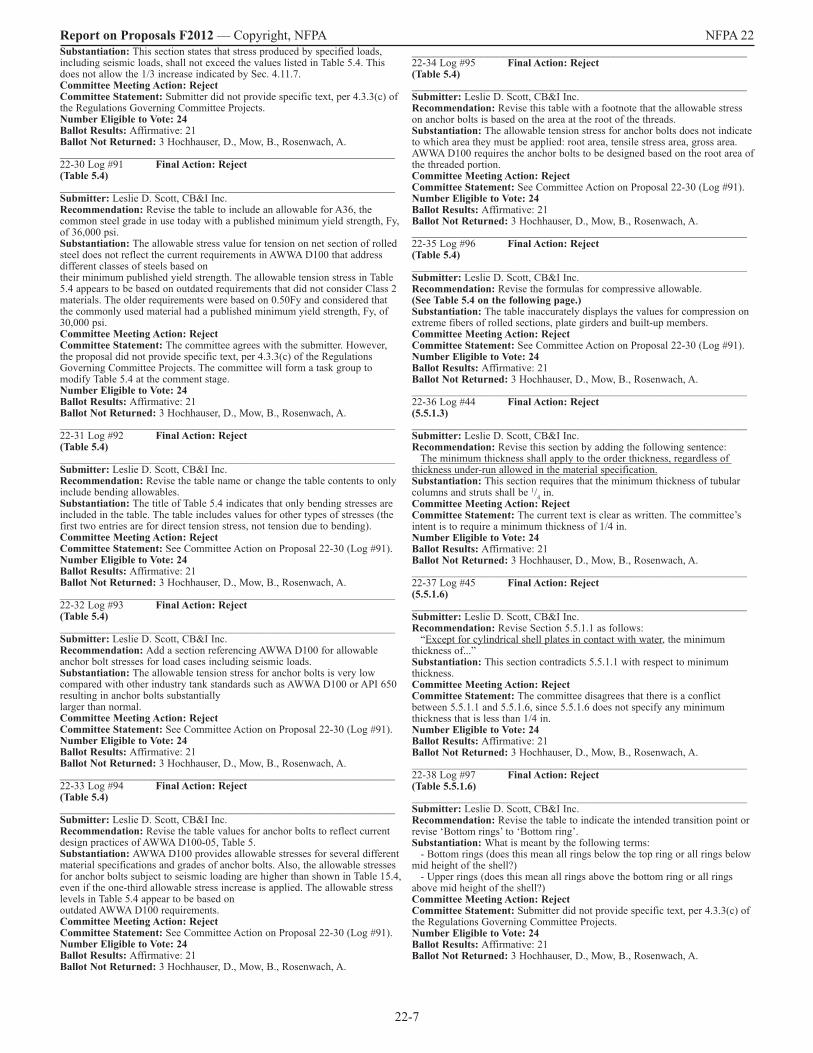
Report on Proposals F2012 — Copyright, NFPA NFPA 22 Substantiation: This section states that stress produced by specified loads, including seismic loads, shall not exceed the values listed in Table 5.4. This does not allow the 1/3 increase indicated by Sec. 4.11.7. Committee Meeting Action: RejectCommittee Statement: Submitter did not provide specific text, per 4.3.3(c) of the Regulations Governing Committee Projects. Number Eligible to Vote: 24 Ballot Results: Affirmative: 21 Ballot Not Returned: 3 Hochhauser, D., Mow, B., Rosenwach, A._______________________________________________________________ 22-30 Log #91 Final Action: Reject(Table 5.4)_______________________________________________________________ Submitter: Leslie D. Scott, CB&I Inc.Recommendation: Revise the table to include an allowable for A36, the common steel grade in use today with a published minimum yield strength, Fy, of 36,000 psi. Substantiation: The allowable stress value for tension on net section of rolled steel does not reflect the current requirements in AWWA D100 that address different classes of steels based on their minimum published yield strength. The allowable tension stress in Table 5.4 appears to be based on outdated requirements that did not consider Class 2 materials. The older requirements were based on 0.50Fy and considered that the commonly used material had a published minimum yield strength, Fy, of 30,000 psi. Committee Meeting Action: RejectCommittee Statement: The committee agrees with the submitter. However, the proposal did not provide specific text, per 4.3.3(c) of the Regulations Governing Committee Projects. The committee will form a task group to modify Table 5.4 at the comment stage. Number Eligible to Vote: 24 Ballot Results: Affirmative: 21 Ballot Not Returned: 3 Hochhauser, D., Mow, B., Rosenwach, A._______________________________________________________________ 22-31 Log #92 Final Action: Reject(Table 5.4)_______________________________________________________________ Submitter: Leslie D. Scott, CB&I Inc.Recommendation: Revise the table name or change the table contents to only include bending allowables. Substantiation: The title of Table 5.4 indicates that only bending stresses are included in the table. The table includes values for other types of stresses (the first two entries are for direct tension stress, not tension due to bending). Committee Meeting Action: RejectCommittee Statement: See Committee Action on Proposal 22-30 (Log #91).Number Eligible to Vote: 24 Ballot Results: Affirmative: 21 Ballot Not Returned: 3 Hochhauser, D., Mow, B., Rosenwach, A._______________________________________________________________ 22-32 Log #93 Final Action: Reject(Table 5.4)_______________________________________________________________ Submitter: Leslie D. Scott, CB&I Inc.Recommendation: Add a section referencing AWWA D100 for allowable anchor bolt stresses for load cases including seismic loads. Substantiation: The allowable tension stress for anchor bolts is very low compared with other industry tank standards such as AWWA D100 or API 650 resulting in anchor bolts substantially larger than normal. Committee Meeting Action: RejectCommittee Statement: See Committee Action on Proposal 22-30 (Log #91).Number Eligible to Vote: 24 Ballot Results: Affirmative: 21 Ballot Not Returned: 3 Hochhauser, D., Mow, B., Rosenwach, A._______________________________________________________________ 22-33 Log #94 Final Action: Reject(Table 5.4)_______________________________________________________________ Submitter: Leslie D. Scott, CB&I Inc.Recommendation: Revise the table values for anchor bolts to reflect current design practices of AWWA D100-05, Table 5. Substantiation: AWWA D100 provides allowable stresses for several different material specifications and grades of anchor bolts. Also, the allowable stresses for anchor bolts subject to seismic loading are higher than shown in Table 15.4, even if the one-third allowable stress increase is applied. The allowable stress levels in Table 5.4 appear to be based on outdated AWWA D100 requirements. Committee Meeting Action: RejectCommittee Statement: See Committee Action on Proposal 22-30 (Log #91).Number Eligible to Vote: 24 Ballot Results: Affirmative: 21 Ballot Not Returned: 3 Hochhauser, D., Mow, B., Rosenwach, A.
_______________________________________________________________ 22-34 Log #95 Final Action: Reject(Table 5.4)_______________________________________________________________ Submitter: Leslie D. Scott, CB&I Inc.Recommendation: Revise this table with a footnote that the allowable stress on anchor bolts is based on the area at the root of the threads. Substantiation: The allowable tension stress for anchor bolts does not indicate to which area they must be applied: root area, tensile stress area, gross area. AWWA D100 requires the anchor bolts to be designed based on the root area of the threaded portion. Committee Meeting Action: RejectCommittee Statement: See Committee Action on Proposal 22-30 (Log #91).Number Eligible to Vote: 24 Ballot Results: Affirmative: 21 Ballot Not Returned: 3 Hochhauser, D., Mow, B., Rosenwach, A._______________________________________________________________ 22-35 Log #96 Final Action: Reject(Table 5.4)_______________________________________________________________ Submitter: Leslie D. Scott, CB&I Inc.Recommendation: Revise the formulas for compressive allowable.(See Table 5.4 on the following page.)Substantiation: The table inaccurately displays the values for compression on extreme fibers of rolled sections, plate girders and built-up members. Committee Meeting Action: RejectCommittee Statement: See Committee Action on Proposal 22-30 (Log #91).Number Eligible to Vote: 24 Ballot Results: Affirmative: 21 Ballot Not Returned: 3 Hochhauser, D., Mow, B., Rosenwach, A._______________________________________________________________ 22-36 Log #44 Final Action: Reject(5.5.1.3)_______________________________________________________________ Submitter: Leslie D. Scott, CB&I Inc.Recommendation: Revise this section by adding the following sentence: The minimum thickness shall apply to the order thickness, regardless of thickness under-run allowed in the material specification.Substantiation: This section requires that the minimum thickness of tubular columns and struts shall be 1/4 in.Committee Meeting Action: RejectCommittee Statement: The current text is clear as written. The committee’s intent is to require a minimum thickness of 1/4 in. Number Eligible to Vote: 24 Ballot Results: Affirmative: 21 Ballot Not Returned: 3 Hochhauser, D., Mow, B., Rosenwach, A._______________________________________________________________ 22-37 Log #45 Final Action: Reject(5.5.1.6)_______________________________________________________________ Submitter: Leslie D. Scott, CB&I Inc.Recommendation: Revise Section 5.5.1.1 as follows: “Except for cylindrical shell plates in contact with water, the minimum thickness of...” Substantiation: This section contradicts 5.5.1.1 with respect to minimum thickness. Committee Meeting Action: RejectCommittee Statement: The committee disagrees that there is a conflict between 5.5.1.1 and 5.5.1.6, since 5.5.1.6 does not specify any minimum thickness that is less than 1/4 in. Number Eligible to Vote: 24 Ballot Results: Affirmative: 21 Ballot Not Returned: 3 Hochhauser, D., Mow, B., Rosenwach, A._______________________________________________________________ 22-38 Log #97 Final Action: Reject(Table 5.5.1.6)_______________________________________________________________ Submitter: Leslie D. Scott, CB&I Inc.Recommendation: Revise the table to indicate the intended transition point or revise ‘Bottom rings’ to ‘Bottom ring’. Substantiation: What is meant by the following terms: - Bottom rings (does this mean all rings below the top ring or all rings below mid height of the shell?) - Upper rings (does this mean all rings above the bottom ring or all rings above mid height of the shell?) Committee Meeting Action: RejectCommittee Statement: Submitter did not provide specific text, per 4.3.3(c) of the Regulations Governing Committee Projects. Number Eligible to Vote: 24 Ballot Results: Affirmative: 21 Ballot Not Returned: 3 Hochhauser, D., Mow, B., Rosenwach, A.

22-8
Report on Proposals F2012 — Copyright, NFPA NFPA 22
_______________________________________________________________ 22-39 Log #46 Final Action: Accept in Principle(5.5.2.2.1)_______________________________________________________________ Submitter: Leslie D. Scott, CB&I Inc.Recommendation: Revise Section 5.5.2.2 as follows: “Except for tubular sections, the sections shall be...”Substantiation: This section requires tubular sections to be hermetically sealed. If they are hermetically sealed tubular sections, then they cannot be open sections as required by 5.5.2.2. Committee Meeting Action: Accept in PrincipleRevise text to read as follows: 5.5.2.2 Except for hermetically-sealed tubular sections, the sections shall be open to facilitate cleaning and painting. 5.5.2.2.1 Tubular sections used for columns on elevated legged tanks shall be hermetically sealed to prevent internal corrosion. Committee Statement: Not all tubular sections are hermetically sealed.Number Eligible to Vote: 24 Ballot Results: Affirmative: 21 Ballot Not Returned: 3 Hochhauser, D., Mow, B., Rosenwach, A._______________________________________________________________ 22-40 Log #47 Final Action: Reject(5.5.2.3)_______________________________________________________________ Submitter: Leslie D. Scott, CB&I Inc.Recommendation: Revise this section by specifying the salt concentration and the types of salt intended to be covered. Substantiation: This section includes requirements for tanks that are to contain salt. How much salt must be present to be considered a ‘tank that is to contain salt’? Does this requirement apply to table salt or sea salt only, or does it apply to other salts as well? Committee Meeting Action: Reject
Committee Statement: Submitter did not provide specific text, per 4.3.3(c) of the Regulations Governing Committee Projects. Number Eligible to Vote: 24 Ballot Results: Affirmative: 21 Ballot Not Returned: 3 Hochhauser, D., Mow, B., Rosenwach, A._______________________________________________________________ 22-41 Log #48 Final Action: Reject(5.5.2.3)_______________________________________________________________ Submitter: Leslie D. Scott, CB&I Inc.Recommendation: Revise this section by specifying the salt concentration above which the corrosion allowance applies. Substantiation: This section includes requirements for tanks that are to contain salt. Was this intended to mean ‘tanks that are to contain salt water’? If so, is there a minimum concentration at which the corrosion allowance applies? Committee Meeting Action: RejectCommittee Statement: Submitter did not provide specific text, per 4.3.3(c) of the Regulations Governing Committee Projects. Number Eligible to Vote: 24 Ballot Results: Affirmative: 21 Ballot Not Returned: 3 Hochhauser, D., Mow, B., Rosenwach, A._______________________________________________________________ 22-42 Log #49 Final Action: Reject(5.5.2.3)_______________________________________________________________ Submitter: Leslie D. Scott, CB&I Inc.Recommendation: Revise this section by specifying the pH range(s) for which the corrosion allowance applies. Substantiation: This section includes corrosion allowance requirements for tanks that are to contain alkaline water. If the pH of the water exceeds 7 it is considered alkaline, even if it is only
Proposal 22-35 (Log #96 ) Recommendation

22-9
Report on Proposals F2012 — Copyright, NFPA NFPA 22 7.1. For purposes of this requirement for corrosion allowance, there must be a pH level at which the water is to be considered alkaline and a corrosion problem. Committee Meeting Action: RejectCommittee Statement: Submitter did not provide specific text, per 4.3.3(c) of the Regulations Governing Committee Projects. Number Eligible to Vote: 24 Ballot Results: Affirmative: 21 Ballot Not Returned: 3 Hochhauser, D., Mow, B., Rosenwach, A._______________________________________________________________ 22-43 Log #50 Final Action: Reject(5.5.3.4)_______________________________________________________________ Submitter: Leslie D. Scott, CB&I Inc.Recommendation: Revise this section to include the 1/3 increase in allowable stress for load cases including seismic loads (per Sec. 4.11.7 or AWWA D100). (see also related comment on Sec. 5.4). Substantiation: This section allows tank design in accordance with AWWA D100, Sec. 14. Under AWWA D100 Sec. 14 design, a 1/3 increase in allowable stresses would apply for the seismic load case. Does the 1/3 increase in allowable stress provided in AWWA D100 apply for this case? If this option is not selected, does the 1/3 increase in allowable stress of Sec. 4.11.7 apply for the seismic load case? Committee Meeting Action: RejectCommittee Statement: Submitter did not provide specific text, per 4.3.3(c) of the Regulations Governing Committee Projects. Number Eligible to Vote: 24 Ballot Results: Affirmative: 21 Ballot Not Returned: 3 Hochhauser, D., Mow, B., Rosenwach, A._______________________________________________________________ 22-44 Log #51 Final Action: Accept in Principle in Part(5.5.3.5)_______________________________________________________________ Submitter: Leslie D. Scott, CB&I Inc.Recommendation: Revise the language to reference AWWA D100 requirements for allowable local buckling stress; or Revise to say ‘… the selected plate thickness shall comply with the allowable local buckling provide allowable local buckling stresses of this standard.’ And then add provisions for allowable local buckling stresses. Substantiation: This section includes a requirement that in cases where compressive stresses exist, the selected plate thickness shall prevent local buckling. The design requirements cannot prevent local buckling, but we can design within the allowable local buckling stresses to achieve the recommended strength for buckling resistance. Committee Meeting Action: Accept in Principle in PartRevise text to read as follows: 5.5.3.5 Where compressive stresses exist, the selected plate thickness shall prevent local buckling in accordance with AWWA D100.Committee Statement: The committee agrees with the submitter’s substantiation, but specific text was not provided. Between the options proposed by the submitter, the committee prefers to reference AWWA D100. Number Eligible to Vote: 24 Ballot Results: Affirmative: 21 Ballot Not Returned: 3 Hochhauser, D., Mow, B., Rosenwach, A._______________________________________________________________ 22-45 Log #53 Final Action: Accept in Part(5.5.7.1.1)_______________________________________________________________ Submitter: Leslie D. Scott, CB&I Inc.Recommendation: Delete this exception or rewrite this section in conjunction with Sec. 5.5.3. Substantiation: This requirement (5.5.7.1) shall not apply to plate thicknesses calculated in accordance with Sec. 5.5.3. Based on review of the standard, it appears that all tank plates must be calculated in accordance with Sec. 5.5.3, so this exception means that it does apply to any tank plates. Committee Meeting Action: Accept in Part Delete Section 5.5.7.1.1. Committee Statement: The committee agrees with the submitter’s recommendation to remove 5.5.7.1.1. Number Eligible to Vote: 24 Ballot Results: Affirmative: 21 Ballot Not Returned: 3 Hochhauser, D., Mow, B., Rosenwach, A._______________________________________________________________ 22-46 Log #54 Final Action: Reject(5.5.8.1)_______________________________________________________________ Submitter: Leslie D. Scott, CB&I Inc.Recommendation: Revise this section to read: The longitudinal joints in adjacent circumferential courses shall be staggered or shall be aligned. Substantiation: The entire Chapter 5 is for welded steel tanks.Committee Meeting Action: Reject
Committee Statement: Submitter did not provide a technical justification.Number Eligible to Vote: 24 Ballot Results: Affirmative: 21 Ballot Not Returned: 3 Hochhauser, D., Mow, B., Rosenwach, A._______________________________________________________________ 22-47 Log #55 Final Action: Accept in Principle(5.5.8.3)_______________________________________________________________ Submitter: Leslie D. Scott, CB&I Inc.Recommendation: Because 5.5.8.3 applies to all tank plates, delete Sec. 5.5.8 and all subsections or rewrite the exception to match the intent. Substantiation: Permission to use 4-way junctions shall not apply to plate thicknesses in accordance with Sec. 5.5.3. Based on review of the standard, it appears that all tank plates addresses in Sec. 5.5.8 must be calculated in accordance with Sec. 5.5.3, so it appears that Sec. 5.5.8.3 negates the validity of Sec. 5.8 Committee Meeting Action: Accept in Principle Delete section 5.5.8. Committee Statement: The committee agrees with the submitter and chooses to delete the section. Number Eligible to Vote: 24 Ballot Results: Affirmative: 21 Ballot Not Returned: 3 Hochhauser, D., Mow, B., Rosenwach, A._______________________________________________________________ 22-48 Log #1 Final Action: Reject(5.5.10.2)_______________________________________________________________ Submitter: Steven Adolphsen, CBI ServicesRecommendation: Revise text as follows: The roof purlin depth shall NOT be less than 1/30 of the span length.Substantiation: Limiting depth causes purlins to be springy and adds to ponding on roof due to mid span deflection. If lateral stability is of concern, then specify bracing (we use 12.5’ max). Committee Meeting Action: RejectCommittee Statement: See Committee Action on Proposal 22-50 (Log #CP2).Number Eligible to Vote: 24 Ballot Results: Affirmative: 21 Ballot Not Returned: 3 Hochhauser, D., Mow, B., Rosenwach, A._______________________________________________________________ 22-49 Log #56 Final Action: Reject(5.5.10.2)_______________________________________________________________ Submitter: Leslie D. Scott, CB&I Inc.Recommendation: Revise the term ‘shall’ should be ‘may’ allowing rafters to be less than L/30 rather than requiring it, or Revise the term ‘shall’ to ‘shall not’ if it is intended to require stiffer roofs for NFPA 22 tanks than would otherwise be provided for AWWA D100 water tanks. Substantiation: This requirement is an inadvertent error when updating from earlier editions of AWWA and AISC requirements. Under the 1955 edition of AWWA D100, based on the then applicable AISC specifications for design of structural steel (June 1949 edition), D100 included an exception to the requirements of the AISC rules. The AISC specification at that time required that the depth of roof purlins be no less than 1/30 of the span. AWWA D100 then required design in accordance with the AISC specification except that the minimum depth of roof rafters may be less than 1/30 of the span. Later editions of the AISC specification eliminated the minimum depth of members support roofs. AWWA D100 requirements continued to carry the exception until the 1973 edition, where the exception was only allowed as long as the design roof pitch was at least 3/4 :12 in order to minimize ponding. Then, in the 2005 edition, AWWA D100 was revised to require a minimum roof slope of ¾:12, therefore the reference to minimum depth has been deleted. It appears that at some point, the NFPA standard decided to revise the language from ‘may be less than 1/30 of the span length’ to ‘shall be less than 1/30 of the span length’, but failed to realize that the language in AWWA D100 was stated as ‘may be less’ because it was an exception to the AISC requirement. So, when the language in NFPA 22 was revised, ‘may’ should have changed to ‘shall not’. As stated in the current standard, this requires rafters of relatively short depth which produces springy roof structures with more deflection. The current AWWA D100 requires a minimum roof slope of ¾:12, therefore the reference to minimum depth has been deleted. Committee Meeting Action: RejectCommittee Statement: See Committee Action on Proposal 22-50 (Log #CP2).Number Eligible to Vote: 24 Ballot Results: Affirmative: 21 Ballot Not Returned: 3 Hochhauser, D., Mow, B., Rosenwach, A.

22-10
Report on Proposals F2012 — Copyright, NFPA NFPA 22 _______________________________________________________________ 22-50 Log #CP2 Final Action: Accept(5.5.10.2)_______________________________________________________________ Submitter: Technical Committee on Water Tanks, Recommendation: Delete Section 5.5.10.2.Substantiation: This section is being removed for compatibility with AWWA D100. Committee Meeting Action: AcceptNumber Eligible to Vote: 24 Ballot Results: Affirmative: 21 Ballot Not Returned: 3 Hochhauser, D., Mow, B., Rosenwach, A._______________________________________________________________ 22-51 Log #57 Final Action: Accept(5.6.2)_______________________________________________________________ Submitter: Leslie D. Scott, CB&I Inc.Recommendation: Revise Sec. 5.6.2 to only apply to elevated tanks as follows: ‘For elevated tanks, plates shall be …’ Add a new section to 5.6 referencing erection tolerances from AWWA D100 as follows: ‘Tanks shall meet the erection tolerance requirements of AWWA D100.’ Substantiation: Current industry standards only require rolling of shell plates for elevated steel tanks. Also, under AWWA D100, all tanks must meet specific erection tolerances to confirm validity of design for compressive loads. Committee Meeting Action: AcceptNumber Eligible to Vote: 24 Ballot Results: Affirmative: 21 Ballot Not Returned: 3 Hochhauser, D., Mow, B., Rosenwach, A._______________________________________________________________ 22-52 Log #52 Final Action: Accept in Principle(5.6.5.1)_______________________________________________________________ Submitter: Leslie D. Scott, CB&I Inc.Recommendation: Delete this section or rewrite to coordinate with Sec. 4.14.1. Substantiation: It seems that ‘… prevent circulation of air over the surface of the water’ prevents open vents above the top capacity line which conflicts with Sec. 4.14.1 that requires a vent. Committee Meeting Action: Accept in Principle Revise text to read as follows: 5.6.5.1 The roof shall fit tightly to the top of the tank to prevent the circulation of air over the surface of the water shell to eliminate any gap between the roof and the shell. Committee Statement: The revised text clarifies the intent of the section.Number Eligible to Vote: 24 Ballot Results: Affirmative: 21 Ballot Not Returned: 3 Hochhauser, D., Mow, B., Rosenwach, A._______________________________________________________________ 22-53 Log #58 Final Action: Accept in Principle(5.6.5.1)_______________________________________________________________ Submitter: Leslie D. Scott, CB&I Inc.Recommendation: Delete the words: ‘…to prevent the circulation of air over the surface of the water.’ Substantiation: Roof fitted tight to the top of the tank does not prevent the circulation of air over the surface of the water. Which is the requirement: roof fitted tight to the top of the tank or prevention of air circulation of the surface of the water? Why is this required? Committee Meeting Action: Accept in PrincipleCommittee Statement: See Committee Action on Proposal 22-52 (Log# 52).Number Eligible to Vote: 24 Ballot Results: Affirmative: 21 Ballot Not Returned: 3 Hochhauser, D., Mow, B., Rosenwach, A._______________________________________________________________ 22-54 Log #59 Final Action: Accept(5.6.7.1.2)_______________________________________________________________ Submitter: Leslie D. Scott, CB&I Inc.Recommendation: Revise this section to reference that the sand base shall conform to the requirements of AWWA D100 as follows: ‘The sand pad, including pH range of the lime sand mix, sulfate content and chloride content shall meet the requirements of AWWA D100.’ Substantiation: This section requires a lime treatment of the undertank sand pad to achieve a pH between 6.5 and 7.5 and limits the chloride content to 300 ppm and the sulfate content to 1000 ppm. For corrosion protection of the underside of the tank bottom, AWWA D100 requires limits on chlorides of 200 ppm and sulfates of 100 ppm and, if the sand is treated with lime, a minimum pH of 10.5 for the lime sand mix.
Are the higher limits of chlorides and sulfates and low pH range required by NFPA 22 based on testing or research or is this requirement a holdover from previous editions? Committee Meeting Action: AcceptNumber Eligible to Vote: 24 Ballot Results: Affirmative: 21 Ballot Not Returned: 3 Hochhauser, D., Mow, B., Rosenwach, A._______________________________________________________________ 22-55 Log #60 Final Action: Accept in Principle(5.7.3.1, 5.7.3.5, and 5.7.4.1)_______________________________________________________________ Submitter: Leslie D. Scott, CB&I Inc.Recommendation: Revise the language by deleting the reference to the inside ladder being located at the second hatch and adding language that an inside ladder be provided for access to the tank floor. Substantiation: Sections 5.7.3.1, 5.7.3.5 and 5.7.4.1 contain the following requirements: - An easily accessible roof hatch … shall be provided. - A second roof hatch shall be place 180° from the existing roof hatch with a ladder to access the tank floor. - Outside and inside steel ladders that are arranged for convenient passage from one to the other and through the roof hatch shall be provided. From these requirements, the inside ladder will be 180° apart from the outside ladder since the outside ladder will provide easy access to the first hatch, and the inside ladder is located at the second hatch. (See Figure on the following page.)Committee Meeting Action: Accept in Principle Revise text to read as follows: 5.7.3.5 A second roof hatch shall be placed 180 degrees from the primary existing roof hatch with a ladder to access the tank floor.5.7.4.1 Outside and inside steel ladders that are arranged for convenient passage from one to the other and through the primary roof hatch shall be provided. Revise Fig B.1(I) to show secondary roof hatch 180 deg from primary roof hatch. Delete the centerline of the hatch.(See Figure B.1(I) on page 12.)Committee Statement: The revised language clarifies the committee’s intent that a second interior ladder is not required. The purpose of the second roof hatch is for ventilation. Number Eligible to Vote: 24 Ballot Results: Affirmative: 21 Ballot Not Returned: 3 Hochhauser, D., Mow, B., Rosenwach, A._______________________________________________________________ 22-56 Log #61 Final Action: Reject(5.7.5.4)_______________________________________________________________ Submitter: Leslie D. Scott, CB&I Inc.Recommendation: Revise section 5.7.5.4 to read: ‘All outside ladders shall be …’Substantiation: Section 5.7.5 addresses ‘Outside Fixed Shell and Roof Ladder’. Committee Meeting Action: RejectCommittee Statement: The text is located under the Outside Ladder section.Number Eligible to Vote: 24 Ballot Results: Affirmative: 21 Ballot Not Returned: 3 Hochhauser, D., Mow, B., Rosenwach, A._______________________________________________________________ 22-57 Log #62 Final Action: Accept in Principle(5.7.8.1)_______________________________________________________________ Submitter: Leslie D. Scott, CB&I Inc.Recommendation: Revise text to read as follows: Except for the underside of the floor on ground-supported flat-bottom tanks, interior dry surfaces of single pedestal tanks, and faying surfaces of bolted joints that prohibit coatings, parts that are inaccessible after fabrication shall be protected by paint before assembly. Substantiation: Clarify ‘… but that are subject to corrosion …’ - Does this mean only interior parts exposed to the stored water or vapor zone? - Does it include exterior weather exposed parts? - Is it only intended to exclude parts such is inside dry surfaces (pedestal tanks) or inaccessible parts that are hermetically sealed from the water, water vapor, or weather? Committee Meeting Action: Accept in Principle Revise text to read as follows: 5.7.8.1 Except for the underside of the floor on ground-supported flat-bottom tanks, parts that are inaccessible after fabrication, but that are subject to corrosion, shall be protected by paint before assembly. Committee Statement: The rejected parts of the proposal are covered under the definition of parts that are inaccessible after fabrication. Number Eligible to Vote: 24 Ballot Results: Affirmative: 21 Ballot Not Returned: 3 Hochhauser, D., Mow, B., Rosenwach, A.
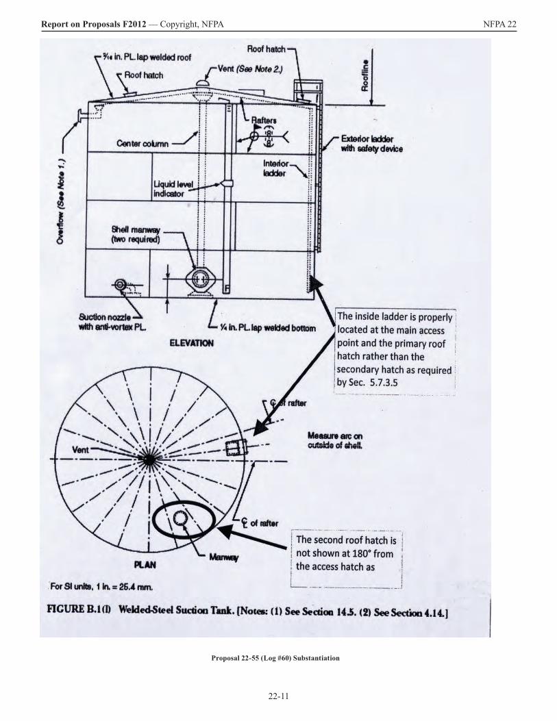
22-11
Report on Proposals F2012 — Copyright, NFPA NFPA 22
Proposal 22-55 (Log #60) Substantiation

22-12
Report on Proposals F2012 — Copyright, NFPA NFPA 22
³⁄₁₆ in. PL. lap welded roof
Roof hatch
Roof hatch
Roo
flineVent (See Note 2.)
Exterior ladderwith safety device
Interior ladder
Ove
rflo
w (
See
Not
e 1.
)
Suction nozzlewith anti-vortex PL.
Shell manway(two required)
Liquid levelindicator
Center column
¹⁄₄ in. PL. lap welded bottom
F
Rafters
ELEVATION WELDING DETAIL
1¹⁄₂ in.
Roof
1¹⁄₂ in.
Bottom
1³⁄₄ in.
Shell to bottom
¹⁄₄
¹⁄₄
³⁄₁₆
For SI units, 1 in. = 25.4 mm.
Vent
of rafterCL
Manway
of rafterCL
Measure arc on outside
of shell
PLAN
For SI units, 1 in. = 25.4 mm.
Proposal 22-55 (Log #60) Committee Action
Figure B.1(l) Welded-Steel Suction Tank. [Notes: (1) See Section 14.6 (2) See Section 4.14.]

22-13
Report on Proposals F2012 — Copyright, NFPA NFPA 22 _______________________________________________________________ 22-58 Log #63 Final Action: Reject(5.7.8.1)_______________________________________________________________ Submitter: Leslie D. Scott, CB&I Inc.Recommendation: Revise this section to state either ‘… protected by primer …’ or ‘… protected by full coating system…’ Substantiation: This section requires that parts that are inaccessible after fabrication, but that are subject to corrosion, shall be protected by paint before assembly. It is unclear whether ‘protected by paint’ means primed and finish coated or whether the primer coat of paint is sufficient. Committee Meeting Action: RejectCommittee Statement: The intent of the standard is not to dictate how many coats of paint are required to protect steel. It is up to the purchaser to determine. Number Eligible to Vote: 24 Ballot Results: Affirmative: 21 Ballot Not Returned: 3 Hochhauser, D., Mow, B., Rosenwach, A._______________________________________________________________ 22-59 Log #64 Final Action: Reject(5.7.8.1)_______________________________________________________________ Submitter: Leslie D. Scott, CB&I Inc.Recommendation: Revise the language to clarify that this requirement does not apply to the underside of tank bottoms that are covered by Section 5.6.7. Substantiation: This section as written does not exclude applicability to underside of tank bottoms. Committee Meeting Action: RejectCommittee Statement: See Committee Action on Proposal 22-57 (Log# 62).Number Eligible to Vote: 24 Ballot Results: Affirmative: 21 Ballot Not Returned: 3 Hochhauser, D., Mow, B., Rosenwach, A._______________________________________________________________ 22-60 Log #65 Final Action: Accept(5.7.8.2)_______________________________________________________________ Submitter: Leslie D. Scott, CB&I Inc.Recommendation: Delete this section.Substantiation: We haven’t used riveted tank construction for sixty of seventy years and this requirement is in the section for welded steel tanks, so I have no clue what is intended by this requirement. It is improbable that suitable welding procedure specifications can be developed to weld a joint that includes oil or lacquer on the surfaces contained inside the joint such as contact surfaces between two members being completely welded together. Committee Meeting Action: AcceptNumber Eligible to Vote: 24 Ballot Results: Affirmative: 21 Ballot Not Returned: 3 Hochhauser, D., Mow, B., Rosenwach, A._______________________________________________________________ 22-61 Log #66 Final Action: Accept(5.7.9.1)_______________________________________________________________ Submitter: Leslie D. Scott, CB&I Inc.Recommendation: Revise this section by deleting the words: ‘…, or pickling in accordance with SSPC SP 8, …’ Substantiation: SSPC SP8 may not give suitable profile for adhesion of coatings. Most coating systems today require a surface profile not achievable by pickling. Committee Meeting Action: AcceptNumber Eligible to Vote: 24 Ballot Results: Affirmative: 21 Ballot Not Returned: 3 Hochhauser, D., Mow, B., Rosenwach, A._______________________________________________________________ 22-62 Log #67 Final Action: Reject(5.7.9.1)_______________________________________________________________ Submitter: Leslie D. Scott, CB&I Inc.Recommendation: Revise the section to address the following items: 1. Allow weld margins on components to be welded together in the field after being primed in the shop. 2. Not require coatings on faying surfaces of structural bolted joints that prohibit coatings. Substantiation: None given.Committee Meeting Action: RejectCommittee Statement: The submitter did not provide specific language or technical substantiation. Number Eligible to Vote: 24 Ballot Results: Affirmative: 21 Ballot Not Returned: 3 Hochhauser, D., Mow, B., Rosenwach, A.
_______________________________________________________________ 22-63 Log #68 Final Action: Accept(5.7.9.2)_______________________________________________________________ Submitter: Leslie D. Scott, CB&I Inc.Recommendation: Revise this section by deleting the words: ‘…, or pickling in accordance with SSPC SP 8, …’ Substantiation: SSPC SP8 may not give suitable profile for adhesion of coatings. Most coating systems today require a surface profile not achievable by pickling. Committee Meeting Action: AcceptNumber Eligible to Vote: 24 Ballot Results: Affirmative: 21 Ballot Not Returned: 3 Hochhauser, D., Mow, B., Rosenwach, A._______________________________________________________________ 22-64 Log #69 Final Action: Accept in Principle(5.7.9.2)_______________________________________________________________ Submitter: Leslie D. Scott, CB&I Inc.Recommendation: Revise the section to address the following items: Delete the words ‘lead-free’. This requirement is covered by Sec. 5.7.12 Revise the language to clearly not require priming on the underside of the floor unless Sec. 5.6.7.1.1 applies.’ Substantiation: Revise to allow weld margins on components to be welded together in the field after being primed in the shop. Committee Meeting Action: Accept in Principle Revise text to read as follows: 5.7.9.2 All exterior surfaces and inside dry surfaces (pedestal tanks) shall be cleaned by commercial blasting in accordance with SSPC SP 6, or pickling in accordance with SSPC SP 8, and shall be primed with one coated of lead-free alkyd in accordance with the requirements of for “Outside Paint System No. 1” of AWWA D102.Committee Statement: The committee removed the words “lead free” and added language to coincide with AWWA D102. Number Eligible to Vote: 24 Ballot Results: Affirmative: 21 Ballot Not Returned: 3 Hochhauser, D., Mow, B., Rosenwach, A._______________________________________________________________ 22-65 Log #70 Final Action: Reject(5.7.9.2)_______________________________________________________________ Submitter: Leslie D. Scott, CB&I Inc.Recommendation: Revise the language to clearly not require priming on the underside of the floor unless Sec. 5.6.7.1.1 applies. Substantiation: None given.Committee Meeting Action: RejectCommittee Statement: See Committee Action on Proposal 22-57 (Log# 62).Number Eligible to Vote: 24 Ballot Results: Affirmative: 21 Ballot Not Returned: 3 Hochhauser, D., Mow, B., Rosenwach, A._______________________________________________________________ 22-66 Log #71 Final Action: Accept in Principle(5.7.9.4)_______________________________________________________________ Submitter: Leslie D. Scott, CB&I Inc.Recommendation: Revise the section to include ‘unprimed surfaces’ as follows: After construction, all weld seams, unprimed surfaces, and any areas…” Substantiation: As written, this section implies that the tank components must be primed prior to erection even though Sec. 5.7.9.1 and 5.7.9.2 do not require that. Committee Meeting Action: Accept in Principle Revise text to read as follows: 5.7.9.4 After construction, all weld seams, unprimed margins, or and any areas where the primer (if preprimed) has been damaged shall be blast-cleaned and patch-primed with the same primer. Committee Statement: The revised text removes the implication that all components must be shop primed. Number Eligible to Vote: 24 Ballot Results: Affirmative: 21 Ballot Not Returned: 3 Hochhauser, D., Mow, B., Rosenwach, A._______________________________________________________________ 22-67 Log #72 Final Action: Accept in Principle(5.7.9.5)_______________________________________________________________ Submitter: Leslie D. Scott, CB&I Inc.Recommendation: Revise to read ‘… interior surfaces (exposed to stored water or the vapor zone) …’ (See also comment related to Sec. 5.7.9.6.) Substantiation: This section provides requirements for finish coats of interior surfaces exposed to stored water, but fails to include those interior surfaces exposed to the vapor zone.
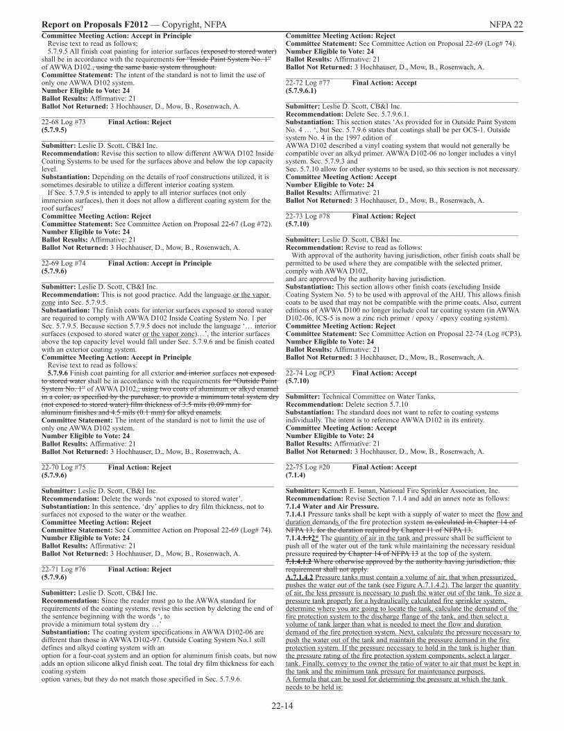
22-14
Report on Proposals F2012 — Copyright, NFPA NFPA 22 Committee Meeting Action: Accept in Principle Revise text to read as follows; 5.7.9.5 All finish coat painting for interior surfaces (exposed to stored water) shall be in accordance with the requirements for “Inside Paint System No. 1” of AWWA D102., using the same basic system throughout.Committee Statement: The intent of the standard is not to limit the use of only one AWWA D102 system. Number Eligible to Vote: 24 Ballot Results: Affirmative: 21 Ballot Not Returned: 3 Hochhauser, D., Mow, B., Rosenwach, A._______________________________________________________________ 22-68 Log #73 Final Action: Reject(5.7.9.5)_______________________________________________________________ Submitter: Leslie D. Scott, CB&I Inc.Recommendation: Revise this section to allow different AWWA D102 Inside Coating Systems to be used for the surfaces above and below the top capacity level. Substantiation: Depending on the details of roof constructions utilized, it is sometimes desirable to utilize a different interior coating system. If Sec. 5.7.9.5 is intended to apply to all interior surfaces (not only immersion surfaces), then it does not allow a different coating system for the roof surfaces? Committee Meeting Action: RejectCommittee Statement: See Committee Action on Proposal 22-67 (Log #72).Number Eligible to Vote: 24 Ballot Results: Affirmative: 21 Ballot Not Returned: 3 Hochhauser, D., Mow, B., Rosenwach, A._______________________________________________________________ 22-69 Log #74 Final Action: Accept in Principle(5.7.9.6)_______________________________________________________________ Submitter: Leslie D. Scott, CB&I Inc.Recommendation: This is not good practice. Add the language or the vapor zone into Sec. 5.7.9.5.Substantiation: The finish coats for interior surfaces exposed to stored water are required to comply with AWWA D102 Inside Coating System No. 1 per Sec. 5.7.9.5. Because section 5.7.9.5 does not include the language ‘… interior surfaces (exposed to stored water or the vapor zone)…’, the interior surfaces above the top capacity level would fall under Sec. 5.7.9.6 and be finish coated with an exterior coating system. Committee Meeting Action: Accept in Principle Revise text to read as follows: 5.7.9.6 Finish coat painting for all exterior and interior surfaces not exposed to stored water shall be in accordance with the requirements for “Outside Paint System No. 1” of AWWA D102., using two coats of aluminum or alkyd enamel in a color, as specified by the purchaser, to provide a minimum total system dry (not exposed to stored water) film thickness of 3.5 mils (0.09 mm) for aluminum finishes and 4.5 mils (0.1 mm) for alkyd enamels.Committee Statement: The intent of the standard is not to limit the use of only one AWWA D102 system. Number Eligible to Vote: 24 Ballot Results: Affirmative: 21 Ballot Not Returned: 3 Hochhauser, D., Mow, B., Rosenwach, A._______________________________________________________________ 22-70 Log #75 Final Action: Reject(5.7.9.6)_______________________________________________________________ Submitter: Leslie D. Scott, CB&I Inc.Recommendation: Delete the words ‘not exposed to stored water’.Substantiation: In this sentence, ‘dry’ applies to dry film thickness, not to surfaces not exposed to the water or the weather. Committee Meeting Action: RejectCommittee Statement: See Committee Action on Proposal 22-69 (Log# 74).Number Eligible to Vote: 24 Ballot Results: Affirmative: 21 Ballot Not Returned: 3 Hochhauser, D., Mow, B., Rosenwach, A._______________________________________________________________ 22-71 Log #76 Final Action: Reject(5.7.9.6)_______________________________________________________________ Submitter: Leslie D. Scott, CB&I Inc.Recommendation: Since the reader must go to the AWWA standard for requirements of the coating systems, revise this section by deleting the end of the sentence beginning with the words ‘, to provide a minimum total system dry …’ Substantiation: The coating system specifications in AWWA D102-06 are different than those in AWWA D102-97. Outside Coating System No.1 still defines and alkyd coating system with an option for a four-coat system and an option for aluminum finish coats, but now adds an option silicone alkyd finish coat. The total dry film thickness for each coating system option varies, but they do not match those specified in Sec. 5.7.9.6.
Committee Meeting Action: RejectCommittee Statement: See Committee Action on Proposal 22-69 (Log# 74).Number Eligible to Vote: 24 Ballot Results: Affirmative: 21 Ballot Not Returned: 3 Hochhauser, D., Mow, B., Rosenwach, A._______________________________________________________________ 22-72 Log #77 Final Action: Accept(5.7.9.6.1)_______________________________________________________________ Submitter: Leslie D. Scott, CB&I Inc.Recommendation: Delete Sec. 5.7.9.6.1.Substantiation: This section states ‘As provided for in Outside Paint System No. 4 … ‘, but Sec. 5.7.9.6 states that coatings shall be per OCS-1. Outside system No. 4 in the 1997 edition of AWWA D102 described a vinyl coating system that would not generally be compatible over an alkyd primer. AWWA D102-06 no longer includes a vinyl system. Sec. 5.7.9.3 and Sec. 5.7.10 allow for other systems to be used, so this section is not necessary. Committee Meeting Action: AcceptNumber Eligible to Vote: 24 Ballot Results: Affirmative: 21 Ballot Not Returned: 3 Hochhauser, D., Mow, B., Rosenwach, A._______________________________________________________________ 22-73 Log #78 Final Action: Reject(5.7.10)_______________________________________________________________ Submitter: Leslie D. Scott, CB&I Inc.Recommendation: Revise to read as follows: With approval of the authority having jurisdiction, other finish coats shall be permitted to be used where they are compatible with the selected primer, comply with AWWA D102, and are approved by the authority having jurisdiction. Substantiation: This section allows other finish coats (excluding Inside Coating System No. 5) to be used with approval of the AHJ. This allows finish coats to be used that may not be compatible with the prime coats. Also, current editions of AWWA D100 no longer include coal tar coating system (in AWWA D102-06, ICS-5 is now a zinc rich primer / epoxy / epoxy coating system). Committee Meeting Action: RejectCommittee Statement: See Committee Action on Proposal 22-74 (Log #CP3).Number Eligible to Vote: 24 Ballot Results: Affirmative: 21 Ballot Not Returned: 3 Hochhauser, D., Mow, B., Rosenwach, A._______________________________________________________________ 22-74 Log #CP3 Final Action: Accept(5.7.10)_______________________________________________________________ Submitter: Technical Committee on Water Tanks, Recommendation: Delete section 5.7.10 Substantiation: The standard does not want to refer to coating systems individually. The intent is to reference AWWA D102 in its entirety. Committee Meeting Action: AcceptNumber Eligible to Vote: 24 Ballot Results: Affirmative: 21 Ballot Not Returned: 3 Hochhauser, D., Mow, B., Rosenwach, A._______________________________________________________________ 22-75 Log #20 Final Action: Accept(7.1.4)_______________________________________________________________ Submitter: Kenneth E. Isman, National Fire Sprinkler Association, Inc.Recommendation: Revise Section 7.1.4 and add an annex note as follows:7.1.4 Water and Air Pressure.7.1.4.1 Pressure tanks shall be kept with a supply of water to meet the flow and duration demands of the fire protection system as calculated in Chapter 14 of NFPA 13, for the duration required by Chapter 11 of NFPA 13. 7.1.4.1.12* The quantity of air in the tank and pressure shall be sufficient to push all of the water out of the tank while maintaining the necessary residual pressure required by Chapter 14 of NFPA 13 at the top of the system.7.1.4.1.2 Where otherwise approved by the authority having jurisdiction, this requirement shall not apply. A.7.1.4.2 Pressure tanks must contain a volume of air, that when pressurized, pushes the water out of the tank (see Figure A.7.1.4.2). The larger the quantity of air, the less pressure is necessary to push the water out of the tank. To size a pressure tank properly for a hydraulically calculated fire sprinkler system, determine where you are going to locate the tank, calculate the demand of the fire protection system to the discharge flange of the tank, and then select a volume of tank larger than what is needed to meet the flow and duration demand of the fire protection system. Next, calculate the pressure necessary to push the water out of the tank and maintain the pressure demand in the fire protection system. If the pressure necessary to hold in the tank is higher than the pressure rating of the fire protection system components, select a larger tank. Finally, convey to the owner the ratio of water to air that must be kept in the tank and the minimum tank pressure for maintenance purposes. A formula that can be used for determining the pressure at which the tank needs to be held is:
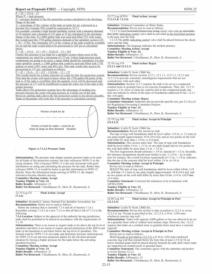
22-15
Report on Proposals F2012 — Copyright, NFPA NFPA 22 Pi = (Pf + 15)/A – 15Where Pi = tank pressurePf = pressure demand of the fire protection system calculated to the discharge flange of the tank A = percentage of the volume of the tank set aside for air, expressed as a decimal (for example 50% would be expressed as “0.5”) For example, consider a light hazard sprinkler system with a duration demand of 30 minutes and a demand of 125 gpm at 55 psi calculated to the discharge flange of the tank. If a 5000 gallon tank was used and filled 75% with water, this would meet the 3750 gallon duration demand of the sprinkler system (125 × 30 = 3750). The remaining 25% of the volume of the tank would be available for air and the tank would need to be pressurized to 265 psi as calculated below: Pi = (Pf + 15)/A – 15 = (55 + 15)/0.25 – 15 = 265Clearly this pressure is too high for a sprinkler system where most of the components are rated for a maximum of 175 psi. Unless high pressure rated components are going to be used, a larger thank should be considered. For this same sprinkler system, a 7,000 gallon tank could be used and filled with 3750 gallons of water (54% water and 46% air). This tank would only need to be pressurized to 137 psi, calculated as follows: Pi = (Pf + 15)/A – 15 = (55 + 15)/0.46 – 15 = 137This would clearly be a better selection of a tank for this fire protection system. Note that the owner will need to know where the 3750 gallon fill point of the tank is. If the tank is overfilled, then the quantity of air will be decreased and the pressure of 137 will be insufficient to push the water out of the tank at the proper pressure. Tanks above fire protection systems have the advantage of needing less pressure because the water will gain pressure as it drops out of the tank. However, putting tanks above the fire protection system is not always possible. Tanks in basements will work fine if the pressure is calculated correctly.
Portion of tank for air
Portion of tank for water — must be at least as large as flow demand � duration
Figure A.7.1.4.2 Pressure Tank Substantiation: The pressure tank chapter permits pressure tanks to be used for all kinds of fire protection systems, but only references NFPA 13 in the sizing situation. This is because NFPA 13 is the only document with good information on sizing and calculating the pressure for the tank. Rather than reference NFPA 13, it would be better to put this information in NFPA 22 directly. Since the information keeps moving in NFPA 13, the chapter references become obsolete anyway. Committee Meeting Action: AcceptNumber Eligible to Vote: 24 Ballot Results: Affirmative: 21 Ballot Not Returned: 3 Hochhauser, D., Mow, B., Rosenwach, A._______________________________________________________________ 22-76 Log #21 Final Action: Accept(7.1.6)_______________________________________________________________ Submitter: Kenneth E. Isman, National Fire Sprinkler Association, Inc.Recommendation: Delete text to read as follows: Delete the sentence that is currently 7.1.6 and all of Section 7.1.6.1. Renumber existing 7.1.6.2 as a new 7.1.6 so that all that is left of 7.1.6 is the following: 7.1.6 Location. Subject to the approval of the authority having jurisdiction, tanks shall be permitted to be buried in accordance with the requirements of 7.1.10. Substantiation: There is no reason to require tanks to be above the top level of sprinklers and there is no reason to require special permission of the AHJ to put tanks in the basement or anywhere below the top level of sprinklers. The formula used by NFPA 13 to size tanks and determine pressure (and proposed for NFPA 22 in our previous proposal) adjusts for the elevation pressure situation by forcing a higher pressure for the tanks below the activating sprinklers/nozzles. Committee Meeting Action: AcceptNumber Eligible to Vote: 24 Ballot Results: Affirmative: 21 Ballot Not Returned: 3 Hochhauser, D., Mow, B., Rosenwach, A.
_______________________________________________________________ 22-77 Log #CP10 Final Action: Accept(7.2.3.3 & 7.2.3.4)_______________________________________________________________ Submitter: Technical Committee on Water Tanks, Recommendation: Revise text to read as follows: 7.2.3.3 A listed horizontal bronze-seat swing-check valve and an renewable-disc globe indicating control valve shall be provided in the horizontal position in the pipe near the tank. 7.2.3.4 The globe indicating control valve shall be placed between the check valve and the tank. Substantiation: The language indicates the modern practice.Committee Meeting Action: AcceptNumber Eligible to Vote: 24 Ballot Results: Affirmative: 21 Ballot Not Returned: 3 Hochhauser, D., Mow, B., Rosenwach, A._______________________________________________________________ 22-78 Log #79 Final Action: Reject(12.2.1 and 12.2.1.1)_______________________________________________________________ Submitter: Leslie D. Scott, CB&I Inc.Recommendation: Revise sections 12.2.1, 12.1.1.1, 12.2.1.3, 12.2.2 and 12.2.2.4 to provide consistent, unambiguous requirements that are not contradictory with each other. Substantiation: Section 12.2.1 requires the tank to be set on a compacted crushed stone or granular base or on concrete foundations. Then, Sec. 12.2.11 requires a 3 in. layer of clean dry sand be laid on the compacted grade, but does not indicate to which of the types of foundations addressed in Sec. 12.2.1 this will apply. Committee Meeting Action: RejectCommittee Statement: Submitter did not provide specific text, per 4.3.3(c) of the Regulations Governing Committee Projects. Number Eligible to Vote: 24 Ballot Results: Affirmative: 21 Ballot Not Returned: 3 Hochhauser, D., Mow, B., Rosenwach, A._______________________________________________________________ 22-79 Log #80 Final Action: Accept in Principle(12.2.2.3)_______________________________________________________________ Submitter: Leslie D. Scott, CB&I Inc.Recommendation: Revise this section to read: The tops of ring wall foundations shall be level within ±1/4 in. (± 3.2 mm) in one plate length [approximately 34 ft (10.4 m)], and no two points on the wall shall differ by more than ± 1/4 in. (± 6.4 mm). Substantiation: This section states that ‘The tops of ring wall foundations shall be level within 1/4 in. ± 1/2 in. in one plate length and no two points on the wall shall differ by more than 1/2 in. ± 1/4 in.‘ The first requirement should reference ± 1/8 in. instead of ± 1/2 in. Secondly, the tolerance designations should read similar to just ‘± 1/4 in.’. As it reads now for instance, the overall levelness requirement of 1/2 in. ± 1/4 in. indicates that the top of the concrete shall be level within 1/4 in. to 3/4 in. Committee Meeting Action: Accept in Principle Revise text to read as follows: 12.2.2.3 The tops of ring wall foundations shall be level within 1/4 in. ±1/8 in. (6.4 mm ±3.2 mm) in one plate length [approximately 34 ft (10.4 m)], and no two points on the wall shall differ by more than 1/2 in. ±1/4 in. (12.7 mm ±6.4 mm). Committee Statement: Corrected the tolerances to be in harmony with AWWA D100. Number Eligible to Vote: 24 Ballot Results: Affirmative: 21 Ballot Not Returned: 3 Hochhauser, D., Mow, B., Rosenwach, A._______________________________________________________________ 22-80 Log #81 Final Action: Accept in Principle in Part(12.2.2.4)_______________________________________________________________ Submitter: Leslie D. Scott, CB&I Inc.Recommendation: Revise this section to take exception to 12.2.2 or revise 12.2.2 to say ‘Except as provided in Sec. 12.2.2.4, a 10 in. ‘(254 mm) reinforced concrete ring wall …’ Substantiation: Tanks with capacity 4,000 gallons or less are allowed to be set on a granular berm with or without steel retainer rings. However, Sec. 12.2.2 requires that tanks on a crushed stone or granular berm must have a concrete ringwall. Committee Meeting Action: Accept in Principle in Part Revise text to read as follows: 12.2.2 Except as provided in 12.2.2.4, a A 10 in. (254 mm) reinforced concrete ring wall that extends below the frost line at least 2.5 ft (0.76 m) below finished grade shall be placed directly beneath the tank shell where tanks are supported on crushed stone or granular bases. Committee Statement: The committee agrees with the submitter and prefers to revise Section 12.2.2. Number Eligible to Vote: 24 Ballot Results: Affirmative: 21 Ballot Not Returned: 3 Hochhauser, D., Mow, B., Rosenwach, A.

22-16
Report on Proposals F2012 — Copyright, NFPA NFPA 22 Also, these contradict Sec. 12.4.3.2 that provides for required means of corrosion protection when the bolts (and nuts) are exposed to weather, water, or corrosive environment. None of these methods include encasement in mortar. Committee Meeting Action: RejectCommittee Statement: See Committee Action on Proposal 22-83 (Log # 84).Number Eligible to Vote: 24 Ballot Results: Affirmative: 21 Ballot Not Returned: 3 Hochhauser, D., Mow, B., Rosenwach, A._______________________________________________________________ 22-85 Log #CP11 Final Action: Accept(14.1.11.2)_______________________________________________________________ Submitter: Technical Committee on Water Tanks, Recommendation: Move section 14.1.11.2 to new annex section A.14.1.11.1Substantiation: Unenforceable language was moved to the annex as a recommended practice. Committee Meeting Action: AcceptNumber Eligible to Vote: 24 Ballot Results: Affirmative: 21 Ballot Not Returned: 3 Hochhauser, D., Mow, B., Rosenwach, A._______________________________________________________________ 22-86 Log #19 Final Action: Accept(14.2.13.1)_______________________________________________________________ Submitter: Kenneth E. Isman, National Fire Sprinkler Association, Inc.Recommendation: Revise 14.2.13.1 as follows: 14.2.13.1 The discharge outlet for every suction tank shall be equipped with an anti-vortex plate assembly. Substantiation: There are a couple of little problems with this section. It does not actually refer to the assembly as an “anti-vortex plate assembly”. And it should use the term “suction tank” as earlier defined. This proposal fixes those little issues. More importantly, the combination of this section and the definition of “suction tank” should solve a problem with people eliminating anti-vortex plates from some shaped tanks because they seem to think that they don’t need them. It has always been the position of NFPA 22 that the anti-vortex plate needs to be installed. This hopefully closes a loophole. Committee Meeting Action: AcceptNumber Eligible to Vote: 24 Ballot Results: Affirmative: 21 Ballot Not Returned: 3 Hochhauser, D., Mow, B., Rosenwach, A._______________________________________________________________ 22-87 Log #CP4 Final Action: Accept(14.2.13.2)_______________________________________________________________ Submitter: Technical Committee on Water Tanks, Recommendation: Revise text to read as follows: 14.2.13.2* The assembly shall consist of a horizontal steel plate that is at least twice the diameter of the outlet on an a long radius elbow fitting, where required, mounted at the outlet a distance above the bottom of the tank equal to one-half the diameter of the discharge pipe. Substantiation: The proposed text clarifies the intent of the committee and meets the requirements of the Hydraulic Institute. Committee Meeting Action: AcceptNumber Eligible to Vote: 24 Ballot Results: Affirmative: 21 Ballot Not Returned: 3 Hochhauser, D., Mow, B., Rosenwach, A._______________________________________________________________ 22-88 Log #CP12 Final Action: Reject(14.2.13.2)_______________________________________________________________ Submitter: Technical Committee on Water Tanks, Recommendation: Revise text to read as follows: 14.2.13.2* The assembly shall consist of a horizontal square or round steel plate that is at least twice the diameter of the outlet on an elbow fitting, where required, mounted at the outlet a distance above the bottom of the tank equal to one-half the diameter of the discharge pipe. Substantiation: Revised text would permit the use of a round vortex plate.Committee Meeting Action: RejectCommittee Statement: The committee welcomes public input on the use of a round vortex plate. Number Eligible to Vote: 24 Ballot Results: Affirmative: 21 Ballot Not Returned: 3 Hochhauser, D., Mow, B., Rosenwach, A._______________________________________________________________ 22-89 Log #14 Final Action: Accept in Principle(14.4.1)_______________________________________________________________ Submitter: Kenneth E. Isman, National Fire Sprinkler Association, Inc.Recommendation: Revise text to read as follows: Revise 14.4.1 by adding “except as provided in 14.4.1.1” at the end of the sentence.
_______________________________________________________________ 22-81 Log #82 Final Action: Accept in Principle(12.4.2.1)_______________________________________________________________ Submitter: Leslie D. Scott, CB&I Inc.Recommendation: Revise this section to read: The lower end of the anchor bolts shall terminate in a head, nut, washer plate or u-bolt. Design of the anchor embedment strength shall be in accordance with ACI 318-08. Substantiation: Based on research findings in ACI report ACI 355.1R-91, AWWA D100 does not allow the use of hooked anchor bolts. Is the allowance of hooked bolts in this section based on newer studies or research or is this just a legacy provision that has not been updated? Committee Meeting Action: Accept in Principle Revise text to read as follows: 12.4.2.1 The lower end of the anchor bolts shall be hooked or fitted with an anchor plate terminate in a head, nut, washer plate or u-bolt.12.4.2.2 Design of the anchor embedment strength shall be in accordance with ACI 318-08.Committee Statement: Editorial changes to comply with the Manual of Style.Number Eligible to Vote: 24 Ballot Results: Affirmative: 21 Ballot Not Returned: 3 Hochhauser, D., Mow, B., Rosenwach, A._______________________________________________________________ 22-82 Log #83 Final Action: Accept in Principle(12.4.3.3 and 12.4.3.3.1)_______________________________________________________________ Submitter: Leslie D. Scott, CB&I Inc.Recommendation: Rewrite these sections to eliminate the contradictory provisions. Substantiation: Sec. 12.4.3.3 that requires minimum 11/4 diameter anchor bolts, but Sec. 12.4.3.3.1 provides requirements when anchor bolts are less than 11/4 diameter. Committee Meeting Action: Accept in Principle Revise text to read as follows: 12.4.3.3 Except as provided in 12.4.3.3.1, the minimum size of anchor bolts shall be 1-1/4 in. (32 mm). Committee Statement: The committee believes that the revised text meets the submitter’s intent. Number Eligible to Vote: 24 Ballot Results: Affirmative: 21 Ballot Not Returned: 3 Hochhauser, D., Mow, B., Rosenwach, A._______________________________________________________________ 22-83 Log #84 Final Action: Accept in Part(12.5.1)_______________________________________________________________ Submitter: Leslie D. Scott, CB&I Inc.Recommendation: Delete Sec. 12.5.1, 12.5.1.1 and 12.5.1.2. If necessary, add the option for mortar encasement to Sec. 12.4.3.2. Substantiation: This section requires that the stressed portions of anchor bolts not be exposed. It seems that this requirement prohibits the use of the industry standard detail of an anchor chair used on thousands of tanks to transfer and distribute the anchor load into the tank shell to reduce shell stresses to within allowable levels. This may have been intended to only address double nut type installation on column base plates for elevated tanks. This section is not necessary considering the requirements of Sec. 12.4.3.2. Committee Meeting Action: Accept in Part Delete 12.5.1, 12.5.1.1, and 12.5.1.2. Committee Statement: The committee does not believe that mortar encasement needs to be addressed. Number Eligible to Vote: 24 Ballot Results: Affirmative: 21 Ballot Not Returned: 3 Hochhauser, D., Mow, B., Rosenwach, A._______________________________________________________________ 22-84 Log #85 Final Action: Reject(12.5.1, 12.5.1.1, and 12.5.1.2)_______________________________________________________________ Submitter: Leslie D. Scott, CB&I Inc.Recommendation: Rewrite these sections to eliminate the contradictory provisions as follows: 12.5.1 When the stressed portions of anchor bolts are exposed, they shall be protected by one of the following methods: (a) Cleaning and painting in accordance with Sec. 5.7.9 if the exposed anchor bolts and nuts are accessible for complete cleaning and painting; or (b) Encasement in cement mortar (NOTE: this will require coatings or mortar for stresses portions of galvanized anchor bolts and corrosion-resistant alloy anchor bolts unless option (c) is added to the above.) Substantiation: These sections contain conflicting provisions for anchor bolts. Sec. 12.5.1 states that stressed portions of anchor bolts shall not be exposed. Sec. 12.5.1.1 provides requirements for when the stressed portions are exposed requiring the bolts be encased in mortar in such cases. Sec. 12.5.1.2 specifies circumstances when mortar encasement is not required.
22-17
Report on Proposals F2012 — Copyright, NFPA NFPA 22 Add new section 14.4.1.1 as follows: 14.4.1.1 Where a permanent water supply is not available to refill the tank, an approved plan shall be permitted for manually refilling the tank. During the time that the tank does not have sufficient capacity to meet the demand of the fire protection system(s), the Impairment Procedures of NFPA 25 shall be followed. Substantiation: The requirement for a permanent water supply to be available on-site to refill the tank within 8 hours was added in the 2008 edition, and it is not practical for all applications. Tanks for fire protection exist in desert locations and other dry areas where there is no well or refill supply on hand. In such cases prior to the 2008 edition, tank trucks or barges were permitted to be used to refill the tanks as long as plans were in place and accepted by the AHJ prior to a fire. Such plans should be permitted again as long as the system without water is treated as an impaired system. Committee Meeting Action: Accept in PrincipleRevise text to read as follows: 14.4.1 A permanent pipe connected to a water supply shall be provided to fill the tank, except as provided in 14.4.1.1.14.4.1.1 Where a permanent water supply is not available to refill the tank, an approved plan shall be permitted for manually refilling the tank. 14.4.1.2 During the time that the tank does not have sufficient capacity to meet the demand of the fire protection system(s), the Impairment Procedures of NFPA 25 shall be followed.Committee Statement: Editorial changes to comply with the Manual of Style.Number Eligible to Vote: 24 Ballot Results: Affirmative: 21 Ballot Not Returned: 3 Hochhauser, D., Mow, B., Rosenwach, A._______________________________________________________________ 22-90 Log #24 Final Action: Accept(14.5 (New) )_______________________________________________________________ Submitter: Technical Committee on Fire Pumps, Recommendation: New text to read as follows: Insert New Section 14.5. 14.5 Break Tanks. Where a break tank is used to provide the pump suction water supply, the installation shall comply with this section. 14.5.1 Application. Break tanks are used for one or more of the following reasons: (1) As a backflow prevention device between the city water supply and the fire pump suction (2) To eliminate pressure fluxations in the city water supply and provide a steady suction pressure to the fire pump (3) To augment the city water supply when the volume of water available from the city is inadequate for the fire protection demand 14.5.2 Break Tank Size. The tank shall be sized for a minimum duration of 15 minutes with the fire pump operating at 150 percent of rated capacity. 14.5.3 Refill Mechanism. The refill mechanism shall be listed and arranged for automatic operation. 14.5.3.1 If the break tank capacity is less than the maximum system demand for 30 minutes, the refill mechanism shall meet the requirements in 14.5.3.1.1 through 14.5.3.1.5. 14.5.3.1.1 Dual automatic refill lines, each capable of refilling the tank at a minimum rate of 150 percent of the fire pump(s) capacity, shall be installed. 14.5.3.1.2 If available supplies do not permit refilling the tank at a minimum rate of 150 percent of the rated pump capacity, each refill line shall be capable of refilling the tank at a rate that meets or exceeds 110 percent of the maximum fire protection system design flow. 14.5.3.1.3 A manual tank fill bypass designed for and capable of refilling the tank at a minimum rate of 150 percent of the fire pump(s) capacity shall be provided. 14.5.3.1.4 If available supplies do not permit refilling the tank at a minimum rate of 150 percent of the rated pump capacity, the manual fill bypass shall be capable of refilling the tank at a rate that meets or exceeds 110 percent of the maximum fire protection system design flow. 14.5.3.1.5 A local visible and audible low liquid level signal shall be provided in the vicinity of the tank fill mechanism. 14.5.3.2 If the break tank is sized to provide a minimum duration of 30 minutes of the maximum system demand, the refill mechanism shall meet the requirements in 14.5.3.2.1 through 14.5.3.2.5. 14.5.3.2.1 The refill mechanism shall be designed for and capable of refilling the tank at 110 percent of the rate required to provide the total fire protection system demand [110% (Total Demand - Tank Capacity) / Duration]. 14.5.3.2.2 A manual tank fill bypass designed for and capable of refilling the tank at 110 percent of the rate required to provide the total fire protection system demand [110% (Total Demand - Tank Capacity) / Duration]. 14.5.3.2.3 The pipe between the city connection and the automatic fill valve shall be installed in accordance with NFPA 24, Standard for the Installation of Private Fire Service Mains and Their Appurtenances. 14.5.3.2.4 The automatic filling mechanism shall be maintained at a minimum temperature of 40°F (4.4°C). 14.5.3.2.5 The automatic filling mechanism shall activate a maximum of 4 in. (152 mm) below the overflow level. Resequence existing sections after 14.5.
Substantiation: Guidance for designing break tanks is needed in NFPA 22. This definition is part of the submittal for design guidelines. This submittal to NFPA 22 was accepted by the NFPA 20 committee at the January 2011 ROP meeting in Orlando. This comment was balloted through the Technical Committee on Fire Pumps with the following results: 30 Members Eligible to Vote 5 Not Returned (J. Beals, D. Haagensen, J. McGrath, J. Roberts, and H. Stewart) 25 Affirmative on All 0 Negatives 0 Abstentions Committee Meeting Action: AcceptNumber Eligible to Vote: 24 Ballot Results: Affirmative: 21 Ballot Not Returned: 3 Hochhauser, D., Mow, B., Rosenwach, A._______________________________________________________________ 22-91 Log #3 Final Action: Accept(15.1.1.3)_______________________________________________________________ Submitter: Robert Bourke, Northeastern Regional Fire Code Development Committee Recommendation: Revise text to read as follows: 15.1.1.3 Where a house that is located above grade with no large pit beneath it is used, it shall comply with 15.1.1.3.1 and 15.1.1.3.2 be necessary to place the OS&Y gate valve in the vertical part of the tank discharge pipe and to construct a small brick or concrete pit or well to contain the check valve in the horizontal pipe below the frost line.15.1.1.3.1 The gate valve shall be provided in the vertical part of the tank discharge. 15.1.1.3.2 A small brick or concrete pit or well shall be constructed to contain the check valve in the horizontal pipe below the frost line.Substantiation: The section currently is difficult to read. The proposed rewording shows the two specific requirements as separate and independent and is clearer. Committee Meeting Action: AcceptNumber Eligible to Vote: 24 Ballot Results: Affirmative: 21 Ballot Not Returned: 3 Hochhauser, D., Mow, B., Rosenwach, A._______________________________________________________________ 22-92 Log #CP13 Final Action: Accept(15.1.2.5.1 & 15.1.2.6.1)_______________________________________________________________ Submitter: Technical Committee on Water Tanks, Recommendation: Replace section 15.1.2.5.1 and 15.1.2.6.1 with: Polystyrene shall not be used where the threat of direct exposure to flame exists. Substantiation: Removes unenforceable text.Committee Meeting Action: AcceptNumber Eligible to Vote: 24 Ballot Results: Affirmative: 21 Ballot Not Returned: 3 Hochhauser, D., Mow, B., Rosenwach, A._______________________________________________________________ 22-93 Log #4 Final Action: Accept(15.1.3.1)_______________________________________________________________ Submitter: Robert Bourke, Northeastern Regional Fire Code Development Committee Recommendation: Revise section to read as follows:A valve pit or house shall be of sufficient size to provide a minimum clearance of 12 in. to 18 in. (305 mm to 457 mm) around all contained equipment.Substantiation: The requirement in this section is vague. If the user is permitted to provide only 12 inches, then that is the minimum requirement. As written currently, it sounds as though there is a maximum clearance permitted of 18 inches. The proposed rewording is clearer. Committee Meeting Action: AcceptNumber Eligible to Vote: 24 Ballot Results: Affirmative: 21 Ballot Not Returned: 3 Hochhauser, D., Mow, B., Rosenwach, A._______________________________________________________________ 22-94 Log #CP14 Final Action: Accept(15.1.3.3 & A.15.1.3.3)_______________________________________________________________ Submitter: Technical Committee on Water Tanks, Recommendation: Delete section 15.1.3.3. Move A.15.1.3.3 to A.15.1.3.2.Substantiation: Remove unenforceable text.Committee Meeting Action: AcceptNumber Eligible to Vote: 24 Ballot Results: Affirmative: 21 Ballot Not Returned: 3 Hochhauser, D., Mow, B., Rosenwach, A.
22-18
Report on Proposals F2012 — Copyright, NFPA NFPA 22 _______________________________________________________________ 22-95 Log #5 Final Action: Accept(15.1.3.4)_______________________________________________________________ Submitter: Robert Bourke, Northeastern Regional Fire Code Development Committee Recommendation: Move section to the Annex 15.1.3.4 A valve house that contains only the OS&Y gate in the discharge pipe and the heater can usually be made smaller.A.15.1.3 A valve house that contains only the OS&Y gate in the discharge pipe and the heater can usually be made smaller.Substantiation: There is no requirement statement in this section. It should be placed in the Annex since it provides good guidance information. Committee Meeting Action: AcceptNumber Eligible to Vote: 24 Ballot Results: Affirmative: 21 Ballot Not Returned: 3 Hochhauser, D., Mow, B., Rosenwach, A._______________________________________________________________ 22-96 Log #2 Final Action: Reject(16.1.2)_______________________________________________________________ Submitter: James Whitehead, Los Alamos National LaboratoryRecommendation: Add new text as follows:16.1.2* The heating system shall be of such capacity that the temperature of the coldest water in the tank or riser, or both, is maintained at or above 42°F (5.6°C) during the coldest weather.Substantiation: I propose that the committee agree on what is the acceptable temperature to heat water tanks 40°F or 42°F. It is obvious that 42°F would fulfill both requirements, but I find the lack of consistency to be absurd when considering the cost of these documents. Committee Meeting Action: RejectCommittee Statement: Proposed text is identical to existing text.Number Eligible to Vote: 24 Ballot Results: Affirmative: 21 Ballot Not Returned: 3 Hochhauser, D., Mow, B., Rosenwach, A._______________________________________________________________ 22-97 Log #15 Final Action: Accept(Table 16.1.4(a))_______________________________________________________________ Submitter: Kenneth E. Isman, National Fire Sprinkler Association, Inc.Recommendation: Revise text to read as follows: Revise Note 2 by adding, “and the bottom water surface area” at the end of the second sentence. The second sentence will read, “The minimum radiation surface area shall be the wetted tank steel surface area plus the top water surface area and the bottom water surface area.”Substantiation: For an elevated tank, the wind will create just as much heat loss as it passes across the bottom of the tank as it does passing over the top of the tank. All sides of the tank exposed to the air should be calculated to determine the total heat loss. Committee Meeting Action: AcceptNumber Eligible to Vote: 24 Ballot Results: Affirmative: 21 Ballot Not Returned: 3 Hochhauser, D., Mow, B., Rosenwach, A._______________________________________________________________ 22-98 Log #16 Final Action: Accept(Table 16.1.4(a))_______________________________________________________________ Submitter: Kenneth E. Isman, National Fire Sprinkler Association, Inc.Recommendation: Revise text to read as follows: Delete the Tank Capacity row at the top of the table. Substantiation: It is too confusing having two separate headings for each column (Tank Capacity in Gallons and Square Feet of Tank Surface Area). The critical variable is the square feet of surface area in contact with the cold air. The tank volume is a useless variable. There are an infinite number of combinations of tank diameter and height that would create the same volume of tank, yet all of these combinations have different areas. Consider the 100,000 gallon tank (8th column of the table), which could be a 25 ft diameter tank 28 ft tall or a 40 ft diameter tank 11 ft tall. The first tank would have an area of 3181 sq ft, which is pretty close to the 2845 of the table. But the second tank has an area of 3895 sq ft, which should use the next column of the table to the right. Since the area is the critical variable, the volume should be eliminated. Committee Meeting Action: AcceptNumber Eligible to Vote: 24 Ballot Results: Affirmative: 21 Ballot Not Returned: 3 Hochhauser, D., Mow, B., Rosenwach, A._______________________________________________________________ 22-99 Log #17 Final Action: Accept(Table 16.1.4(c))_______________________________________________________________ Submitter: Kenneth E. Isman, National Fire Sprinkler Association, Inc.Recommendation: Revise text to read as follows: Delete the Tank Capacity row at the top of the table. Substantiation: It is too confusing having two separate headings for each column (Tank Capacity in Gallons and Square Feet of Tank Surface Area). The critical variable is the square feet of surface area in contact with the cold air.
There are an infinite number of combinations of tank diameter and height that would create the same volume of tank, yet all of these combinations have different surface areas. In this particular case, the surface areas are similar. For example, a 250,000 gallon tank (7th column of the table), could be a 40 ft diameter tank 27 ft tall or a 50 ft diameter tank 17 ft tall. The first tank would have an area of 4650 sq ft, and the second tank would have an area of 4633 sq ft. These areas are similar, but since the area is the critical variable, the volume should be eliminated. Committee Meeting Action: AcceptNumber Eligible to Vote: 24 Ballot Results: Affirmative: 21 Ballot Not Returned: 3 Hochhauser, D., Mow, B., Rosenwach, A._______________________________________________________________ 22-100 Log #7 Final Action: Accept in Principle(17.1.1)_______________________________________________________________ Submitter: Jon Nisja, Northcentral Regional Fire Code Development Committee Recommendation: Alter section 17.1.1 as follows: 17.1.1 Prior to placing the tank in service, a representative of the tank contractor, and a representative of the owner and the authority having jurisdiction shall conduct a joint inspection of the completed equipment.Substantiation: The authority having jurisdiction is required to witness inspection and testing of fire protection equipment. Water tanks should be no different. Committee Meeting Action: Accept in PrincipleRevise text to read as follows: 17.1 Inspection of Completed Equipment. 17.1.1 Prior to placing the tank in service, a representative of the tank contractor and a representative of the owner shall conduct a joint inspection of the completed equipment. 17.1.1.1 The authorities having jurisdiction shall be notified as to the time and place of the inspection.17.1.2* Written reports of completed equipment inspections shall be made in triplicate, and a copy that has been signed by the contractors and the owners shall be sent to the authority having jurisdiction. Committee Statement: In order to allow for difficulty in scheduling, the committee does not believe that the presence of the authority having jurisdiction should be mandatory. However, the committee agrees that the authority having jurisdiction should be notified. Number Eligible to Vote: 24 Ballot Results: Affirmative: 21 Ballot Not Returned: 3 Hochhauser, D., Mow, B., Rosenwach, A._______________________________________________________________ 22-101 Log #CP5 Final Action: Accept(17.11)_______________________________________________________________ Submitter: Technical Committee on Water Tanks, Recommendation: Add new Section 17.11 17.11 Anti-Vortex Plate Inspection 17.11.1 After completion of the tank construction, and before filling the tank with water, the anti-vortex plate shall be inspected. 17.11.1.1 The inspection shall verify that the horizontal steel plate and long radius elbow meet the requirements of 14.2.13.2 and are installed in accordance with 14.2.13.3. 17.11.2 The inspection results shall be included in the written report specified in Section 17.1.2. Substantiation: The proposed language is intended to ensure that the anti-vortex plate is properly installed. If the requirements of Section 14.2.13 are not followed, the anti-vortex plate will not function properly. Installation of an anti-vortex plate is critical to preventing the formation of a vortex. If a vortex occurs, there is the potential of introducing air into the suction end of the fire pump, causing cavitation, reduced pump performance and possible pump damage. Committee Meeting Action: AcceptNumber Eligible to Vote: 24 Ballot Results: Affirmative: 21 Ballot Not Returned: 3 Hochhauser, D., Mow, B., Rosenwach, A._______________________________________________________________ 22-102 Log #8 Final Action: Accept in Principle(A.4.2.1)_______________________________________________________________ Submitter: Jon Nisja, Northcentral Regional Fire Code Development Committee Recommendation: Add new annex note: A.4.2.1 Fire exposure risk to a water tank should take into account locations that could be threatened by wildland fire. NFPA 1144 Standard for Protection of Life and Property from Wildfire should be referenced.Substantiation: 4.2 requires an examination of fire exposure hazards from nearby structures. In remote locations the hazard from wildland fires poses a greater risk and should be considered when tank location is determined. Committee Meeting Action: Accept in PrincipleAdd new text to read as follows: A.4.2.1 Fire exposure risk to a water tank should take into account locations that could be threatened by wildland fire. See NFPA 1144 Standard for
22-19
Report on Proposals F2012 — Copyright, NFPA NFPA 22 Protection of Life and Property from Wildfire for more information.Committee Statement: Editorial changes.Number Eligible to Vote: 24 Ballot Results: Affirmative: 21 Ballot Not Returned: 3 Hochhauser, D., Mow, B., Rosenwach, A._______________________________________________________________ 22-103 Log #10 Final Action: Accept(A.14.2.13.3)_______________________________________________________________ Submitter: Kenneth E. Isman, National Fire Sprinkler Association, Inc.Recommendation: Revise text to read as follows: Change A.14.2.13.3 to A.14.2.13 and revise the language as follows: A.14.2.13 See Figure B.1(o), Figure B.1(p), and Figure B.1(q).Substantiation: The figure is of value in explaining the entire concept of the anti-vortex plate, not just the 6 inch dimension that is mentioned in 14.2.13.3, therefore, the figures should be referenced in an annex note attached to the basic concept of anti-vortex plates (14.2.13). The additional figures should be referenced in the annex note as well. Committee Meeting Action: AcceptNumber Eligible to Vote: 24 Ballot Results: Affirmative: 21 Ballot Not Returned: 3 Hochhauser, D., Mow, B., Rosenwach, A._______________________________________________________________ 22-104 Log #CP6 Final Action: Accept(A.17.1.2)_______________________________________________________________ Submitter: Technical Committee on Water Tanks, Recommendation: Add new Section A.17.1.2 as follows: A.17.1.2 See Figure A.17.1.2.(See Figure A.17.1.2 on page 20.) Substantiation: The proposed new Annex Section provides inspectors and testers with a sample form to use. The form serves as a checklist for the inspectors and tester to ensure they have followed the requirements of Chapter 17 properly. Additionally, similar forms are provided in many other NFPA documents, such as NFPA 3 and NFPA 25. Committee Meeting Action: AcceptNumber Eligible to Vote: 24 Ballot Results: Affirmative: 21 Ballot Not Returned: 3 Hochhauser, D., Mow, B., Rosenwach, A._______________________________________________________________ 22-105 Log #86 Final Action: Accept in Principle in Part(Figure B.1(l))_______________________________________________________________ Submitter: Leslie D. Scott, CB&I Inc.Recommendation: For clarity revised these details by deleting the dimensions and weld symbols from these details or delete the details in their entirety. Substantiation: The weld detail at the top right includes dimensions and weld symbols on three sample joint locations for ground-supported welded-steel tanks. Since the requirements in the appendix are not a part of the standard, inclusion of specific details such as dimensions and weld sizes is confusing to the user of the standard. In many cases, inspection or enforcement officials want to impose those as requirements because, even though ‘not a part of the standard’, they are interpreted as recommendations by NFPA. Also, depending on tank size and design and construction details, the weld sizes may be inadequate and the actual dimensions may not match those shown. Specific details such as these, if considered important, should appear in the standard. Since they only appear in the Appendix, they are intended for information, but what information is really necessary for the user of the standard? Committee Meeting Action: Accept in Principle in Part Delete weld symbol in Elevation view only. (See Figure on page 21.) Committee Statement: Weld symbol is not necessary in the elevation view, but should be retained in other views to illustrate where the weld should be located and whether the weld should be single- or double-fillet. Number Eligible to Vote: 24 Ballot Results: Affirmative: 21 Ballot Not Returned: 3 Hochhauser, D., Mow, B., Rosenwach, A._______________________________________________________________ 22-106 Log #87 Final Action: Reject(Figure B.1(l))_______________________________________________________________ Submitter: Leslie D. Scott, CB&I Inc.Recommendation: Revise the welding symbol to reflect AWS welding symbols. (See Figure B.1(l) on page 21.)Substantiation: What is intended by the weld symbol on the shell joints?Committee Meeting Action: RejectCommittee Statement: See Committee Action on Proposal 22-105 (Log# 86).Number Eligible to Vote: 24 Ballot Results: Affirmative: 21 Ballot Not Returned: 3 Hochhauser, D., Mow, B., Rosenwach, A.
_______________________________________________________________ 22-107 Log #11 Final Action: Accept(Figure B.1(o))_______________________________________________________________ Submitter: Kenneth E. Isman, National Fire Sprinkler Association, Inc.Recommendation: Revise text to read as follows: Make the following three changes to Figure B.1(o): (1) Change “Anti-vortex plate (48 in. x 48 in.)” to “Anti-vortex plate (minimum 2D x 2D; frequently, a 48 in. x 48 in. size is used as a standard size that will work for any situation)” (2) Change “6 in.” at the bottom of the figure to “1/2D or 6 in, whichever is greater” (3) Show the diameter of the pipe as “D” Substantiation: These changes are necessary to match the requirements of NFPA 22. The anti-vortex plate is only required to be twice the diameter of the discharge pipe for the tank, yet it is shown as 48 inches by 48 inches. Many AHJ’s don’t understand the rules, but they know how to read a figure and are forcing contractors to replace work that meets the standard. Committee Meeting Action: AcceptNumber Eligible to Vote: 24 Ballot Results: Affirmative: 21 Ballot Not Returned: 3 Hochhauser, D., Mow, B., Rosenwach, A._______________________________________________________________ 22-108 Log #88 Final Action: Reject(Figure B.1(o))_______________________________________________________________ Submitter: Leslie D. Scott, CB&I Inc.Recommendation: Correct the weld symbol for the angle-to-anti-vortex plate weld. Substantiation: The detail is missing dimensions for the flange-to-shell offset and shell-to-CL of elbow. The weld symbol for the angle-to-anti-vortex plate weld indicates a near side and far side weld, but then indicates weld all the way around meaning that those welds would interfere with each other. Clarify the missing dimensions or revise the detail to remove the unused dimension lines. Committee Meeting Action: RejectCommittee Statement: The committee is unclear to the submitter’s intent.Number Eligible to Vote: 24 Ballot Results: Affirmative: 21 Ballot Not Returned: 3 Hochhauser, D., Mow, B., Rosenwach, A._______________________________________________________________ 22-109 Log #89 Final Action: Reject(Figure B.1(o))_______________________________________________________________ Submitter: Leslie D. Scott, CB&I Inc.Recommendation: Revise the weld detail at the right to identify the dimension ‘t’ as the lesser of the reinforcing plate thickness and the pipe wall thickness. Substantiation: In the weld detail at the right, is ‘t’ intended to be the reinforcing plate thickness or the pipe wall thickness? Committee Meeting Action: RejectCommittee Statement: It is not the intent of the standard to specify the “t” dimension. It is up to the fabrication requirements. Number Eligible to Vote: 24 Ballot Results: Affirmative: 21 Ballot Not Returned: 3 Hochhauser, D., Mow, B., Rosenwach, A._______________________________________________________________ 22-110 Log #90 Final Action: Reject(Figure B.1(o))_______________________________________________________________ Submitter: Leslie D. Scott, CB&I Inc.Recommendation: Revise the weld symbol to properly indicate the weld shown or revise the weld detail to match the symbol. Substantiation: The inside pipe-to-shell weld appears to show a full penetration weld with a fillet weld cap, but the weld symbol calls for a fillet weld only. Committee Meeting Action: RejectCommittee Statement: The standard properly details the weld symbol for a full penetration weld with a fillet cap. Number Eligible to Vote: 24 Ballot Results: Affirmative: 21 Ballot Not Returned: 3 Hochhauser, D., Mow, B., Rosenwach, A._______________________________________________________________ 22-111 Log #12 Final Action: Accept(Figure B.1(q))_______________________________________________________________ Submitter: Kenneth E. Isman, National Fire Sprinkler Association, Inc.Recommendation: Revise text to read as follows: Make the following three changes to Figure B.1(q): (1) Change “6 in.” at the bottom of the figure to “1/2D or 6 in, whichever is greater” (2) Show the diameter of the pipe as “D” Substantiation: These changes are necessary to make the figure match the requirements of NFPA 22. For large tanks, the distance will need to be greater than 6 inches. Committee Meeting Action: AcceptNumber Eligible to Vote: 24 Ballot Results: Affirmative: 21 Ballot Not Returned: 3 Hochhauser, D., Mow, B., Rosenwach, A.

22-20
Report on Proposals F2012 — Copyright, NFPA NFPA 22
NFPA 22 (p. 1 of 1)© 2012 National Fire Protection Association
WATER STORAGE TANKS FOR FIRE PROTECTIONINSPECTION CHECKLIST
Date of inspection: Capacity:
Inspector name: Diameter:
Inspector phone #: Height:
Property name: Year built:
Property address:
Joint inspection of completed equipment by a representative of the tank contractor and a representative of the owner. � Yes � No
Anti-vortex plate: size and dimensions correct � Yes � No
Inspections Comments
Welded Steel Tanks:
Has flat bottom? � Yes � No
Has no leaks in the shell, bottom, or roof � Yes � No
Bolted Steel Tanks:
Has no leaks � Yes � No
Pressure Tanks:
Follows ASME Boiler and Pressure Vessel Code? � Yes � No
Hydrostatic test pressure at least 150 psi? � Yes � No
Pressure does not drop more than 0.5 psi in 24 hours after being filled at working pressure and ²⁄₃ its capacity? � Yes � No
Embankment-Supported Coated Fabric Tanks:
Has no leaks prior to shipment or after installation? � Yes � No
Concrete Tanks:
Fill tank, let it sit for 24 hours and measure liquid volume loss over next 72 hours. Has measurable leakage? � Yes � No
Wood Tanks:
Check liquid tightness for 48 hours with the help of qualified wood tank specialist? � Yes � No
In accordance with National Wood Tank Institute Bulletin S82? � Yes � No
Fiberglass-Reinforced Plastic Tanks:
Hydrostatic test performed? � Yes � No
All Tanks:
Disposal of test water? � Yes � No
Tests Comments
Proposal 22-104 (Log #CP6) Recommendation

22-21
Report on Proposals F2012 — Copyright, NFPA NFPA 22
³⁄₁₆ in. PL. lap welded roof
Roof hatch
Roof hatch
Roo
flineVent (See Note 2.)
Exterior ladderwith safety device
Interior ladder
Ove
rflo
w (
See
Not
e 1.
)
Suction nozzlewith anti-vortex PL.
Shell manway(two required)
Liquid levelindicator
Center column
¹⁄₄ in. PL. lap welded bottom
F
Rafters
ELEVATION WELDING DETAIL
1¹⁄₂ in.
Roof
1¹⁄₂ in.
Bottom
1³⁄₄ in.
Shell to bottom
¹⁄₄
¹⁄₄
³⁄₁₆
For SI units, 1 in. = 25.4 mm.
Vent
of rafterCL
Manway
of rafterCL
Measure arc on outside
of shell
PLAN
For SI units, 1 in. = 25.4 mm.
Proposal 22-105 (Log #86) Committee Action
Figure B.1(l) Welded-Steel Suction Tank. [Notes: (1) See Section 14.6 (2) See Section 4.14.]