nfc nutshell kit - scm pc-card · 2018-03-15 · mcu - lpc1769 module this module features the...
TRANSCRIPT
NFC NUTSHELL KIT MCU Modules
USER MANUAL
REVISION 1.23
GMMC GmbH www.gmmc-biz.com
Document information
Info Content Keywords User Manual GMMC
Abstract This document describes how to use MCU Modules of the GMMC´s NFC Nutshell KIT and its related tools
NFC NUTSHELL KIT MCU Modules REVISION 1.23 - 9-MAR-18
All information provided in this document is subject to legal disclaimers. © GMMC GmbH. All rights reserved.
COMPANY PUBLIC User Manual 1 of 16
l
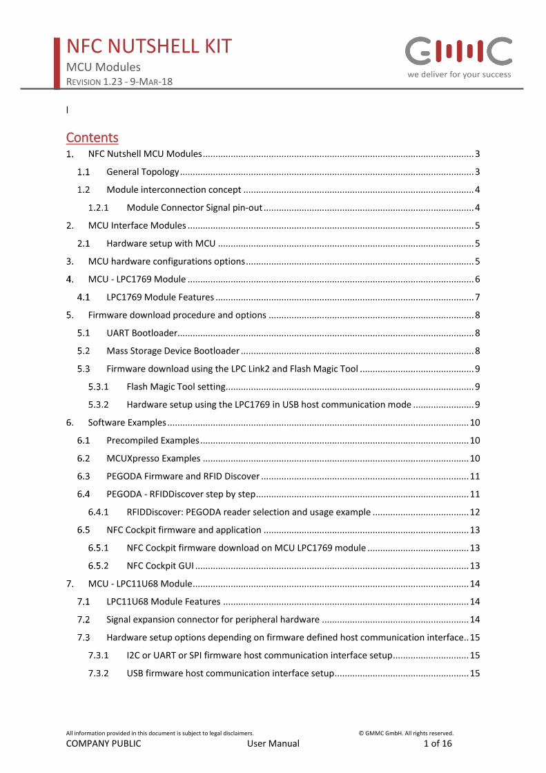
Contents NFC Nutshell MCU Modules ........................................................................................................... 3
General Topology .................................................................................................................... 3
Module interconnection concept ........................................................................................... 4
Module Connector Signal pin-out ................................................................................... 4
MCU Interface Modules ................................................................................................................. 5
Hardware setup with MCU ..................................................................................................... 5
MCU hardware configurations options .......................................................................................... 5
MCU - LPC1769 Module ................................................................................................................. 6
LPC1769 Module Features ...................................................................................................... 7
Firmware download procedure and options ................................................................................. 8
UART Bootloader..................................................................................................................... 8
Mass Storage Device Bootloader ............................................................................................ 8
Firmware download using the LPC Link2 and Flash Magic Tool ............................................. 9
Flash Magic Tool setting .................................................................................................. 9
Hardware setup using the LPC1769 in USB host communication mode ........................ 9
Software Examples ....................................................................................................................... 10
Precompiled Examples .......................................................................................................... 10
MCUXpresso Examples ......................................................................................................... 10
PEGODA Firmware and RFID Discover .................................................................................. 11
PEGODA - RFIDDiscover step by step .................................................................................... 11
RFIDDiscover: PEGODA reader selection and usage example ...................................... 12
NFC Cockpit firmware and application ................................................................................. 13
NFC Cockpit firmware download on MCU LPC1769 module ........................................ 13
NFC Cockpit GUI ............................................................................................................ 13
MCU - LPC11U68 Module ............................................................................................................. 14
LPC11U68 Module Features ................................................................................................. 14
Signal expansion connector for peripheral hardware .......................................................... 14
Hardware setup options depending on firmware defined host communication interface .. 15
I2C or UART or SPI firmware host communication interface setup .............................. 15
USB firmware host communication interface setup ..................................................... 15
NFC NUTSHELL KIT MCU Modules REVISION 1.23 - 9-MAR-18
All information provided in this document is subject to legal disclaimers. © GMMC GmbH. All rights reserved.
COMPANY PUBLIC User Manual 2 of 16
Table of figures Figure 1 Available Kit components and PCB solder mask color .............................................................. 3
Figure 2 Kit modules interconnection via FFC cables ............................................................................. 4
Figure 3 always insert FFC cable straight ................................................................................................ 4
Figure 4 Module Zero Force FFC Connector Signal Pinout ..................................................................... 4
Figure 5 Hardware setup with MCU ....................................................................................................... 5
Figure 6 MCU module connection options. (MCU and NFC module images are examples) .................. 5
Figure 7 Image LPC1769 MCU and SWDIO interface pin-out ................................................................. 6
Figure 8 Image LPC1769 MCU LPCLink 2 connection ............................................................................. 6
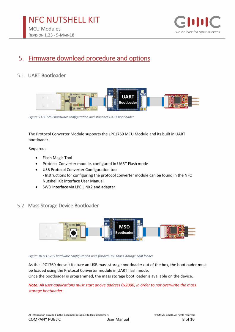
Figure 9 LPC1769 hardware configuration and standard UART bootloader .......................................... 8
Figure 10 LPC1769 hardware configuration with flashed USB Mass Storage boot loader ..................... 8
Figure 11 Flash Magic configuration for LPC Link2 ................................................................................. 9
Figure 12 Hardware setup Firmware Update via Flash Magic Tool and LPC Link2 ................................ 9
Figure 13 LPC1769 hardware configuration for PEGODA firmware download .................................... 11
Figure 14. LPC1769 hardware configuration for PEGODA / RFIDDiscover operation .......................... 11
Figure 15. Select PEGODA within RFIDDiscover .................................................................................... 12
Figure 16. Example RFIDDiscover show cards command ..................................................................... 12
Figure 17 LPC1769 hardware configuration for NFC cockpit firmware download .............................. 13
Figure 18 LPC1769 hardware configuration for NFC cockpit execution ............................................... 13
Figure 19 NFC cockpit start up screen .................................................................................................. 13
Figure 20 Image LPC1769 MCU and SWDIO pin out ............................................................................. 14
Figure 21 Signal pin out on LPC11U68 MCU Module............................................................................ 14
Figure 22 LPC11U68 MCU Module with Protocol converter interface (UART, I2C, SPI) ....................... 15
Figure 23 LPC11U68 MCU Module with USB plug interface (USB communication FW) ...................... 15

NFC NUTSHELL KIT MCU Modules REVISION 1.23 - 9-MAR-18
All information provided in this document is subject to legal disclaimers. © GMMC GmbH. All rights reserved.
COMPANY PUBLIC User Manual 3 of 16
NFC Nutshell MCU Modules
General Topology The Kit consists of different types of modules, which can be connected application specific. Each
module type has a different color.
• Interface
• MCU
• NFC
• Antenna
Figure 1 Available Kit components and PCB solder mask color

NFC NUTSHELL KIT MCU Modules REVISION 1.23 - 9-MAR-18
All information provided in this document is subject to legal disclaimers. © GMMC GmbH. All rights reserved.
COMPANY PUBLIC User Manual 4 of 16
Module interconnection concept The Nutshell Kit can be operated in different configurations. The connection between the different
modules is done via FFC cables and zero force sockets.
The Kit modules can be connected to a host via different interface modules see deztails in the NFC
Nutshell Kit interface module user manual.
Figure 2 Kit modules interconnection via FFC cables
Figure 3 always insert FFC cable straight
Important Notes:
• Open and close the connector carefully.
• Always insert straight – do not apply force
• Avoid cable/connector misalignment – potential short cut and damage
• If you observe communication issues over time, exchange the FFC cable with a spare one.
• DO NOT disconnect, bend or move the Kit while modules are powered to avoid short circuits.
Module Connector Signal pin-out
Figure 4 Module Zero Force FFC Connector Signal Pinout

NFC NUTSHELL KIT MCU Modules REVISION 1.23 - 9-MAR-18
All information provided in this document is subject to legal disclaimers. © GMMC GmbH. All rights reserved.
COMPANY PUBLIC User Manual 5 of 16
MCU Interface Modules Currently the NFC Nutshell KIT supports the following MCUs
• LPC11u68
• LPC1769
• PN7462 (future release)
is considered as NFC Frontend with integrated MCU and will be described in the NFC Module
User manual.
Hardware setup with MCU
Figure 5 Hardware setup with MCU
MCU hardware configurations options
Figure 6 MCU module connection options. (MCU and NFC module images are examples)
NFC NUTSHELL KIT MCU Modules REVISION 1.23 - 9-MAR-18
All information provided in this document is subject to legal disclaimers. © GMMC GmbH. All rights reserved.
COMPANY PUBLIC User Manual 6 of 16
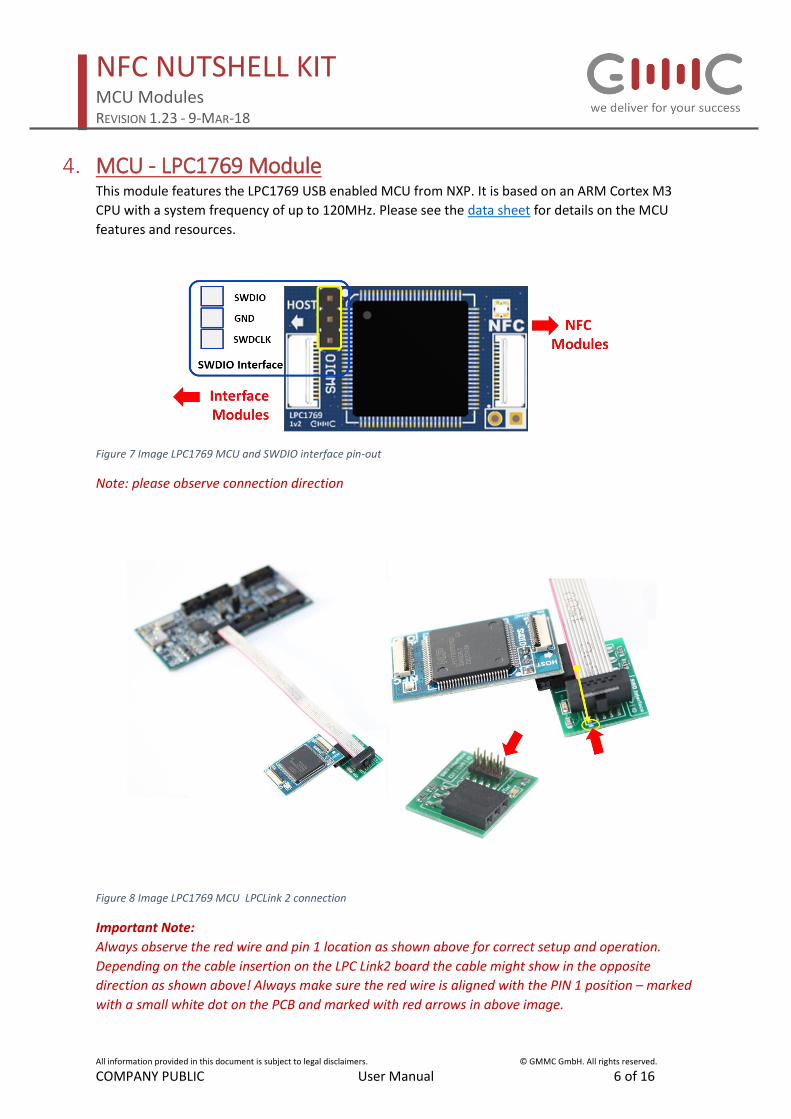
MCU - LPC1769 Module This module features the LPC1769 USB enabled MCU from NXP. It is based on an ARM Cortex M3
CPU with a system frequency of up to 120MHz. Please see the data sheet for details on the MCU
features and resources.
Figure 7 Image LPC1769 MCU and SWDIO interface pin-out
Note: please observe connection direction
Figure 8 Image LPC1769 MCU LPCLink 2 connection
Important Note:
Always observe the red wire and pin 1 location as shown above for correct setup and operation.
Depending on the cable insertion on the LPC Link2 board the cable might show in the opposite
direction as shown above! Always make sure the red wire is aligned with the PIN 1 position – marked
with a small white dot on the PCB and marked with red arrows in above image.
NFC NUTSHELL KIT MCU Modules REVISION 1.23 - 9-MAR-18
All information provided in this document is subject to legal disclaimers. © GMMC GmbH. All rights reserved.
COMPANY PUBLIC User Manual 7 of 16
LPC1769 Module Features • USB Mass Storage Bootloader1
• USB interface 2
• I2C, SPI and UART host interface3
• RGB status LED
• SPI communication to RF Frontend
• RFID Discover with PEGODA firmware
• NFC Cockpit firmware support using CLRC663 and its derivates
• SWDIO debug interface
Notes:
1 USB Mass storage Bootloader firmware needs to be uploaded first, USB plug module with boot
button needs to be used. 2 USB plug module with boot button needs to be used. 3 GMMC´s Protocol converter module required.
The communication to the RF frontend is fixed to the SPI interface. This allows to communicate with
the RF frontend at the maximum speed and hence provides highest performance.
NFC NUTSHELL KIT MCU Modules REVISION 1.23 - 9-MAR-18
All information provided in this document is subject to legal disclaimers. © GMMC GmbH. All rights reserved.
COMPANY PUBLIC User Manual 8 of 16
Firmware download procedure and options
UART Bootloader
Figure 9 LPC1769 hardware configuration and standard UART bootloader
The Protocol Converter Module supports the LPC1769 MCU Module and its built in UART
bootloader.
Required:
• Flash Magic Tool
• Protocol Converter module, configured in UART Flash mode
• USB Protocol Converter Configuration tool
- Instructions for configuring the protocol converter module can be found in the NFC
Nutshell Kit Interface User Manual.
• SWD Interface via LPC LINK2 and adapter
Mass Storage Device Bootloader
Figure 10 LPC1769 hardware configuration with flashed USB Mass Storage boot loader
As the LPC1769 doesn’t feature an USB mass storage bootloader out of the box, the bootloader must
be loaded using the Protocol Converter module in UART flash mode.
Once the bootloader is programmed, the mass storage boot loader is available on the device.
Note: All user applications must start above address 0x2000, in order to not overwrite the mass
storage bootloader.

NFC NUTSHELL KIT MCU Modules REVISION 1.23 - 9-MAR-18
All information provided in this document is subject to legal disclaimers. © GMMC GmbH. All rights reserved.
COMPANY PUBLIC User Manual 9 of 16
Firmware download using the LPC Link2 and Flash Magic Tool
With the help of the FLASH MAgic Tool and the LPC Link2 it is also possible to flash firmware onto
supported MCUs. Set the ISP settings as per below image, connect the LPC Link2 board with the LPC
Link2 adapter and flash the desired firmware into the MCU. Under the ISP menu you will find
different options such as blank checking, verification or device signature read out.
If your MCU firmware features a USB host communication there is no need to use the Protocol
Converter Module for firmware download and then change the interface adapter to USB afterwards.
Simply use the USB plug interface and update your firmware via LPC Link2 and adapter.
Flash Magic Tool setting
Figure 11 Flash Magic configuration for LPC Link2
Hardware setup using the LPC1769 in USB host communication mode
Figure 12 Hardware setup Firmware Update via Flash Magic Tool and LPC Link2
Note: cable direction in above picture depends on cable insertion on LPC Link board. Make sure the
red cable is always aligned with PIN1 position which is marked with a white dot on Adapter PCB.
NFC NUTSHELL KIT MCU Modules REVISION 1.23 - 9-MAR-18
All information provided in this document is subject to legal disclaimers. © GMMC GmbH. All rights reserved.
COMPANY PUBLIC User Manual 10 of 16
Software Examples
Precompiled Examples The NFC Nutshell Kit provides some precompiled firmware examples that run out of the box on this
MCU LPC1769 module. The NFC Nutshell Kit has to be connected properly for correct functionality.
Note:
*.hex files must be programmed using the UART ISP Bootloader mode and the Protocol Converter
module needs to be set to UART Flash Mode.
*.bin files must be flashed using the USB Mass Storage Bootloader (MSD needs to be present
already).
MCUXpresso Examples
The NXP reader library is also available for this microcontroller. It allows the use of different front
NFC front ends. To run an example, you have to do perform the following steps:
Required
• MCUXpresso needs to be installed and working.
• Select Import Project and select the desired *.zip file.
This imports all the selected example of the NXP reader library using the LPC1769 MCU
Module.
• After compiling the source example code it can be downloaded via the UART flash
bootloader and the Protocol Converter Module in flash mode. Or if you change the linker
script it can also be programmed using the mass storage device bootloader.
NFC NUTSHELL KIT MCU Modules REVISION 1.23 - 9-MAR-18
All information provided in this document is subject to legal disclaimers. © GMMC GmbH. All rights reserved.
COMPANY PUBLIC User Manual 11 of 16
PEGODA Firmware and RFID Discover
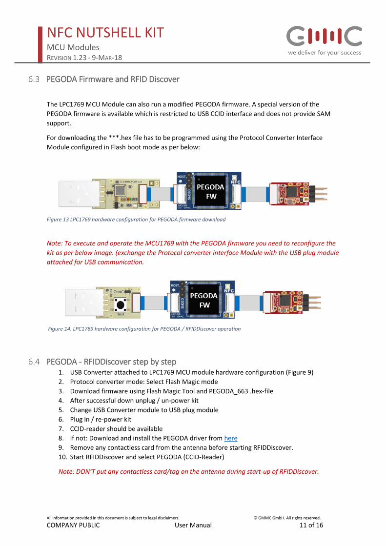
The LPC1769 MCU Module can also run a modified PEGODA firmware. A special version of the
PEGODA firmware is available which is restricted to USB CCID interface and does not provide SAM
support.
For downloading the ***.hex file has to be programmed using the Protocol Converter Interface
Module configured in Flash boot mode as per below:
Figure 13 LPC1769 hardware configuration for PEGODA firmware download
Note: To execute and operate the MCU1769 with the PEGODA firmware you need to reconfigure the
kit as per below image. (exchange the Protocol converter interface Module with the USB plug module
attached for USB communication.
Figure 14. LPC1769 hardware configuration for PEGODA / RFIDDiscover operation
PEGODA - RFIDDiscover step by step 1. USB Converter attached to LPC1769 MCU module hardware configuration (Figure 9).
2. Protocol converter mode: Select Flash Magic mode
3. Download firmware using Flash Magic Tool and PEGODA_663 .hex-file
4. After successful down unplug / un-power kit
5. Change USB Converter module to USB plug module
6. Plug in / re-power kit
7. CCID-reader should be available
8. If not: Download and install the PEGODA driver from here
9. Remove any contactless card from the antenna before starting RFIDDiscover.
10. Start RFIDDiscover and select PEGODA (CCID-Reader)
Note: DON’T put any contactless card/tag on the antenna during start-up of RFIDDiscover.
NFC NUTSHELL KIT MCU Modules REVISION 1.23 - 9-MAR-18
All information provided in this document is subject to legal disclaimers. © GMMC GmbH. All rights reserved.
COMPANY PUBLIC User Manual 12 of 16
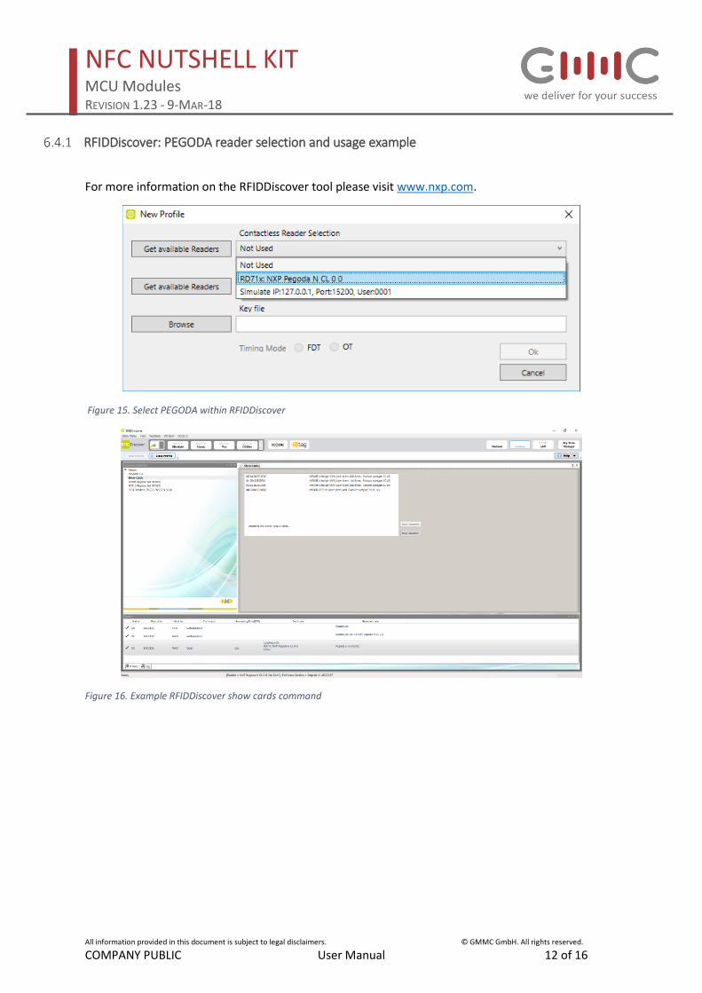
RFIDDiscover: PEGODA reader selection and usage example
For more information on the RFIDDiscover tool please visit www.nxp.com.
Figure 15. Select PEGODA within RFIDDiscover
Figure 16. Example RFIDDiscover show cards command
NFC NUTSHELL KIT MCU Modules REVISION 1.23 - 9-MAR-18
All information provided in this document is subject to legal disclaimers. © GMMC GmbH. All rights reserved.
COMPANY PUBLIC User Manual 13 of 16
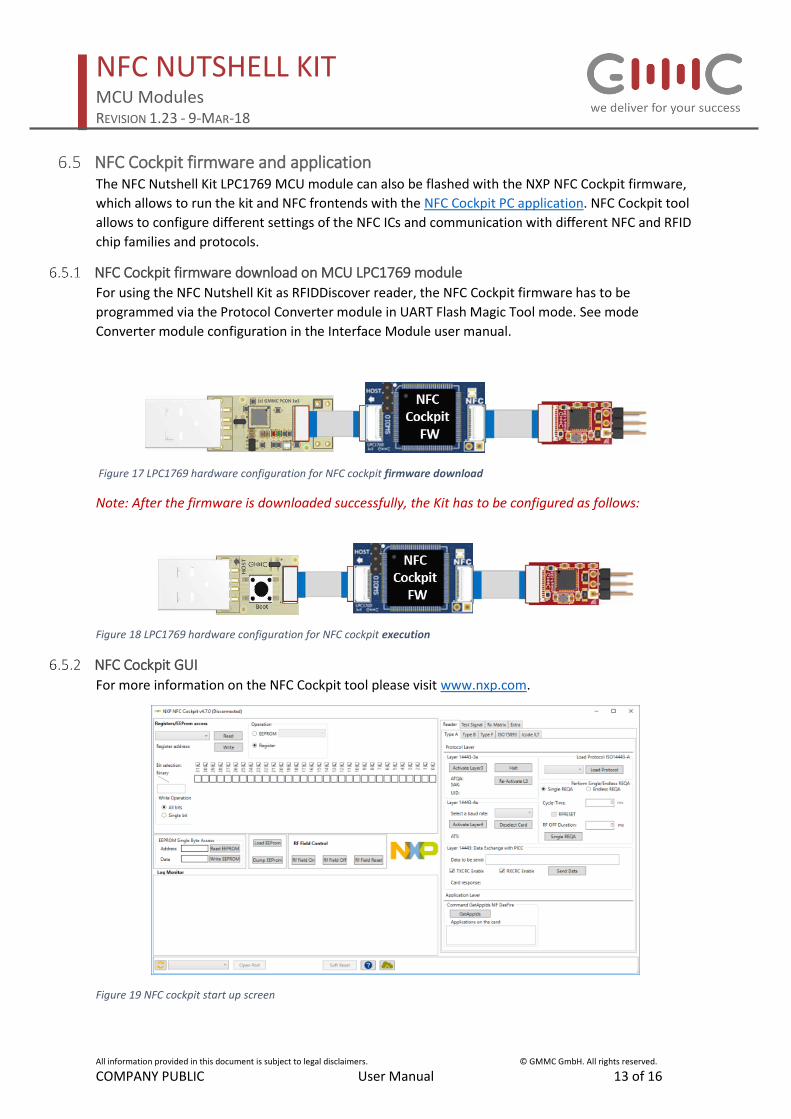
NFC Cockpit firmware and application The NFC Nutshell Kit LPC1769 MCU module can also be flashed with the NXP NFC Cockpit firmware,
which allows to run the kit and NFC frontends with the NFC Cockpit PC application. NFC Cockpit tool
allows to configure different settings of the NFC ICs and communication with different NFC and RFID
chip families and protocols.
NFC Cockpit firmware download on MCU LPC1769 module For using the NFC Nutshell Kit as RFIDDiscover reader, the NFC Cockpit firmware has to be
programmed via the Protocol Converter module in UART Flash Magic Tool mode. See mode
Converter module configuration in the Interface Module user manual.
Figure 17 LPC1769 hardware configuration for NFC cockpit firmware download
Note: After the firmware is downloaded successfully, the Kit has to be configured as follows:
Figure 18 LPC1769 hardware configuration for NFC cockpit execution
NFC Cockpit GUI For more information on the NFC Cockpit tool please visit www.nxp.com.
Figure 19 NFC cockpit start up screen
NFC NUTSHELL KIT MCU Modules REVISION 1.23 - 9-MAR-18
All information provided in this document is subject to legal disclaimers. © GMMC GmbH. All rights reserved.
COMPANY PUBLIC User Manual 14 of 16
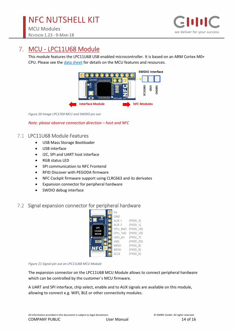
MCU - LPC11U68 Module This module features the LPC11U68 USB enabled microcontroller. It is based on an ARM Cortex M0+
CPU. Please see the data sheet for details on the MCU features and resources.
Figure 20 Image LPC1769 MCU and SWDIO pin out
Note: please observe connection direction – host and NFC
LPC11U68 Module Features • USB Mass Storage Bootloader
• USB interface
• I2C, SPI and UART host interface
• RGB status LED
• SPI communication to NFC Frontend
• RFID Discover with PEGODA firmware
• NFC Cockpit firmware support using CLRC663 and its derivates
• Expansion connector for peripheral hardware
• SWDIO debug interface
Signal expansion connector for peripheral hardware
Figure 21 Signal pin out on LPC11U68 MCU Module
The expansion connector on the LPC11U68 MCU Module allows to connect peripheral hardware
which can be controlled by the customer´s MCU firmware.
A UART and SPI interface, chip select, enable and to AUX signals are available on this module,
allowing to connect e.g. WIFI, BLE or other connectivity modules.

NFC NUTSHELL KIT MCU Modules REVISION 1.23 - 9-MAR-18
All information provided in this document is subject to legal disclaimers. © GMMC GmbH. All rights reserved.
COMPANY PUBLIC User Manual 15 of 16
Hardware setup options depending on firmware defined host communication
interface
I2C or UART or SPI firmware host communication interface setup
Figure 22 LPC11U68 MCU Module with Protocol converter interface (UART, I2C, SPI)
USB firmware host communication interface setup
Figure 23 LPC11U68 MCU Module with USB plug interface (USB communication FW)
Note:
If you experience host communication issues after FW download via the Flash Magic Tool, make sure
you have the correct interface module corresponding to your firmware host interface communication
attached.

NFC NUTSHELL KIT MCU Modules REVISION 1.23 - 9-MAR-18
All information provided in this document is subject to legal disclaimers. © GMMC GmbH. All rights reserved.
COMPANY PUBLIC User Manual 16 of 16
Revision history
Rev Date Description 1.0 2018 Feb. 6th Initial version MGa