nfc forum – iso/iec 14443 analog parameter comparison and...
TRANSCRIPT
NFC Forum – ISO/IEC 14443 Analog Parameter Comparison and Alignment
Methodology, Procedures and Results
Version: 1.5Date: 2017-01-19
NFC Forum – ISO/IEC 14443 Analog Parameter Comparison and Alignment
2
Contents 1 Introduction.............................................................................................................................................................................................. 9
1.1 Motivation and Objectives ............................................................................................................................................................... 9
1.2 Purpose ................................................................................................................................................................................................. 9
1.3 Public Transport Collaborations ................................................................................................................................................... 10
1.4 Outline of This Document .............................................................................................................................................................. 11
2 Boundary Conditions and Methodology for Analog Parameter Comparison ......................................................................... 12
2.1 Interoperability Versus Conformance ......................................................................................................................................... 12
2.2 Boundary Conditions ....................................................................................................................................................................... 13
2.2.1 Generic Considerations on the Antenna Size and Its Impact on Communication Stability .................................... 14
2.3 Methodology ..................................................................................................................................................................................... 14
2.4 Analog Parameters Selected for Comparison............................................................................................................................ 15
3 NFC Forum to ISO/IEC 14443 Comparison (NFC Forum Perspective) .................................................................................... 17
3.1 Polling Device Requirements......................................................................................................................................................... 17
3.1.1 Requirement 4.1.2.1: Power Transfer from Polling Device to Listening Device (Polling Device Transmission)17
a. Minimum field strength ................................................................................................................................................................ 17
b. Maximum field strength .............................................................................................................................................................. 20
c. Minimum and Maximum Field Strength results ..................................................................................................................... 23
3.1.2 Requirement 4.4.2.1: Carrier Frequency fc (Polling Device Transmission) ................................................................. 27
3.1.3 Requirement 4.7.2.1: Listening Device Reset (Polling Device Transmission) ............................................................. 28
a. tFIELD_OFF ........................................................................................................................................................................................... 28
b. VOV,RESET ........................................................................................................................................................................................... 28
3.1.4 Requirement 4.9.2.1: Polling Device RF Collision Avoidance Before Carrier Generation ...................................... 29
3.1.5 Requirements 5.1.2.1 to 5.1.2.7: Modulation Polling Device to Listening Device – NFC-A (Polling Device
Transmission) ........................................................................................................................................................................................... 29
a. Waveform analysis ........................................................................................................................................................................ 29
b. Overshoot and Undershoot analysis ........................................................................................................................................ 30
3.1.6 Requirements 5.3.2.1 to 5.3.2.6: Modulation Polling Device to Listening Device – NFC-B (Polling Device
Transmission) ........................................................................................................................................................................................... 32
a. Waveform analysis ........................................................................................................................................................................ 32
b. Overshoot and Undershoot analysis ........................................................................................................................................ 32
3.1.7 Requirements 5.5.2.1 to 5.5.2.6: Modulation Polling Device to Listening Device – NFC-F (Polling Device
Transmission) ........................................................................................................................................................................................... 34
3.1.8 Requirement 6.5.2.1: Modulation Listening Device to Polling Device (Polling Device Reception) ...................... 34
a. VPP,min ................................................................................................................................................................................................ 34
b. VPP,max ............................................................................................................................................................................................... 41
3.2 Listening Device Requirements .................................................................................................................................................... 43
3.2.1 Requirements 4.2.2.1 & 4.2.2.2 & 4.2.2.3: Power Transfer from Polling Device to Listening Device (Listening
Device Reception) ................................................................................................................................................................................... 43
a. Minimum field strength ................................................................................................................................................................ 43
b. Maximum field strength .............................................................................................................................................................. 45
c. Minimum and Maximum Field strength results ..................................................................................................................... 47
NFC Forum – ISO/IEC 14443 Analog Parameter Comparison and Alignment
3
3.2.2 Requirements 4.3.2.1: Influence of the Listening Device on the Operating Field .................................................... 50
3.2.3 Requirement 4.5.2.1: Carrier Frequency fc (Listening Device Reception) .................................................................. 52
3.2.4 Requirement 4.6.2.1: Power On (Listening Device Reception) ...................................................................................... 53
3.2.5 Requirements 4.8.2.1: Listening Device Reset (Listening Device Reception) ............................................................ 53
a. tFIELD OFF ............................................................................................................................................................................................ 53
b. VOV,RESET ........................................................................................................................................................................................... 53
3.2.6 Requirement 5.2.2.1: Modulation Polling Device to Listening Device – NFC-A (Listening Device Reception) 54
3.2.7 Requirement 5.4.2.1: Modulation Polling Device to Listening Device – NFC-B (Listening Device Reception) 54
3.2.8 Requirement 5.6.2.1: Modulation Polling Device to Listening Device – NFC-F (Listening Device Reception) . 55
3.2.9 Requirement 6.1.2.1 & 6.1.2.2 & 6.2.3.3: Load Modulation Characteristics – Generic (Listening Device
Transmission) ........................................................................................................................................................................................... 55
a. Subcarrier Frequency ................................................................................................................................................................... 55
b. VPP,min ................................................................................................................................................................................................ 55
c. VPP,max ............................................................................................................................................................................................... 62
3.2.10 Requirements 6.2.1.1 & 6.2.1.2: Load Modulation Characteristics – NFC-A (Listening Device Transmission) 64
3.2.11 Requirements 6.3.1.1 & 6.3.1.3: Load Modulation Characteristics – NFC-B (Listening Device Transmission) . 64
3.2.12 Requirement 6.4.1.1: Load Modulation Characteristics – NFC-F (Listening Device Transmission) ..................... 65
4 Limit Harmonization and Validation ................................................................................................................................................. 66
4.1 NFC Forum Polling Device VOV,min Harmonization and Validation ...................................................................................... 66
4.1.1 Minimum Field Strength – HarmonizationPpart 1: Homogenous Field Condition ................................................... 67
4.1.2 Minimum Field Strength – Harmonization Part 2: Heterogeneous Field Condition ................................................ 68
4.1.2.1 SETUP and VERIFICATION harmonization part 2: heterogeneous field condition ..................................... 69
4.1.2.2 Summary H-field reference value assessment ...................................................................................................... 70
4.1.2.3 Problem Analysis ........................................................................................................................................................... 71
4.1.2.4 Validation – SETUP ...................................................................................................................................................... 72
4.1.2.5 Validation – VERIFICATION ...................................................................................................................................... 75
4.2 NFC Forum Listener Minimum Load Modulation Amplitude (VPP, min) Harmonization ................................................... 76
4.2.1 Part1: H-field Versus LMAmin Versus V(dc) Versus AWG LMA Output....................................................................... 79
4.2.1.1 NFC Forum Reference Listening Devices as DUT ............................................................................................... 79
4.2.1.2 ISO Reference PICCs as DUT .................................................................................................................................... 82
4.2.2 Part 2: Verification of LMAmin Harmonization .................................................................................................................... 84
4.2.2.1 NFC LMA Signal Analysis Results: PCD and PICC limit ...................................................................................... 84
4.2.2.2 DFT LMA Signal Analysis Results: PCD and PICC Limit ..................................................................................... 91
4.2.3 Harmonization Result Proposal .............................................................................................................................................. 97
4.2.4 NFC Forum Listener Minimum Load Modulation Amplitude (VPP,min) Validation ...................................................... 99
4.2.4.1 Procedure ....................................................................................................................................................................... 99
4.2.4.2 Validation Results ...................................................................................................................................................... 101
4.2.5 Summary ................................................................................................................................................................................... 115
a. Testing methodology difference analysis ............................................................................................................................. 115
b. Maximum field strength – class 1 antenna size .................................................................................................................. 116
c. CAT C and minimum field strength ........................................................................................................................................ 117
4.2.6 Conclusion ................................................................................................................................................................................ 118
NFC Forum – ISO/IEC 14443 Analog Parameter Comparison and Alignment
4
5 Electromagnetic Disturbance (EMD) ............................................................................................................................................. 119
5.1 EMD Impact Analysis ................................................................................................................................................................... 119
ANNEX A: ISO/IEC 14443 PCD Requirement References ............................................................................................................. 120
A.1. General PCD Requirements for Compliance ............................................................................................................................. 120
A.2. 14443-1 PCD Requirements for Alternating Magnetic Field ................................................................................................ 122
A.3. 14443-2 Requirement on PCD Field Strength .......................................................................................................................... 123
a. Minimum Field Strength ........................................................................................................................................................... 123
b. Maximum Field Strength .......................................................................................................................................................... 123
A.4. ISO/IEC 14443-2 PCD Requirement for Carrier Frequency fc ........................................................................................... 124
A.5. ISO/IEC 14443-2 EMD PCD Requirement ................................................................................................................................ 125
A.6. ISO/IEC 14443-2 PCD Requirement for Resetting the Operating Field............................................................................ 126
a. Timing and Duration of Reset ................................................................................................................................................. 126
b. VOV,reset .......................................................................................................................................................................................... 126
A.7. ISO/IEC 14443-2 PCD Requirements for Power-off of the Operating Field ................................................................... 127
A.8. ISO/IEC 14443-2 PCD Requirements for Modulation PCD to PICC – Type A ................................................................ 128
a. Waveform analysis ..................................................................................................................................................................... 128
b. Overshoot and Undershoot analysis ..................................................................................................................................... 129
A.9. ISO/IEC 14443-2 PCD Requirements for Modulation PCD to PICC – Type B ................................................................ 130
a. Waveform analysis ..................................................................................................................................................................... 130
b. Overshoot and Undershoot analysis ..................................................................................................................................... 130
A.10. ISO/IEC 14443-2 PCD Requirements for Modulation PICC to PCD ............................................................................... 132
a. VPP,min ............................................................................................................................................................................................. 132
b. VPP,max ............................................................................................................................................................................................ 132
ANNEX B: ISO/IEC 14443 PICC Requirements ................................................................................................................................ 133
B.1. 14443-1 PICC Requirements for Alternating Magnetic Field ............................................................................................... 133
B.2. ISO/IEC 14443-2 Power Transfer PCD to PICC (PICC Reception) ..................................................................................... 134
a. Minimum Field Strength ........................................................................................................................................................... 134
b. Maximum Field Strength .......................................................................................................................................................... 134
B.3. ISO/IEC 14443-2 PICC Maximum Loading ................................................................................................................................ 136
B.4. ISO/IEC 14443-2 PICC Requirement for the Carrier Frequency fc .................................................................................... 138
B.5. ISO/IEC 14443-2 EMD PICC Requirement ............................................................................................................................... 139
B.6. ISO/IEC 14443-2 PICC Requirements for Transition to POWER-OFF / IDLE State ...................................................... 140
a. Duration of Transition to POWER-OFF/IDLE state .......................................................................................................... 140
b. VOV,RESET ........................................................................................................................................................................................ 140
B.7. ISO/IEC 14443-2 PICC Requirements for Modulation PCD to PICC – Type A ............................................................... 141
B.8. ISO/IEC 14443-2 PICC Requirements for Modulation PCD to PICC – Type B ............................................................... 143
B.9. ISO/IEC 14443-2 PICC Requirements for Load Modulation ................................................................................................ 145
a. Subcarrier Frequency ................................................................................................................................................................ 145
b. VPP,min ............................................................................................................................................................................................. 145
c. VPP,max ............................................................................................................................................................................................ 145
B.10. ISO/IEC 14443-2 PICC Requirements for Subcarrier Modulation – Type A .................................................................. 146
NFC Forum – ISO/IEC 14443 Analog Parameter Comparison and Alignment
5
B.11. ISO/IEC 14443-2 PICC Requirements for Subcarrier Modulation – Type B .................................................................. 147
ANNEX C: NFC Forum Analog References ......................................................................................................................................... 148
C.1. NFC Forum Listening Devices Antenna Category Definitions (copy from ANALOG v2.0 Annex B.4) ...................... 148
NFC Forum – ISO/IEC 14443 Analog Parameter Comparison and Alignment
6
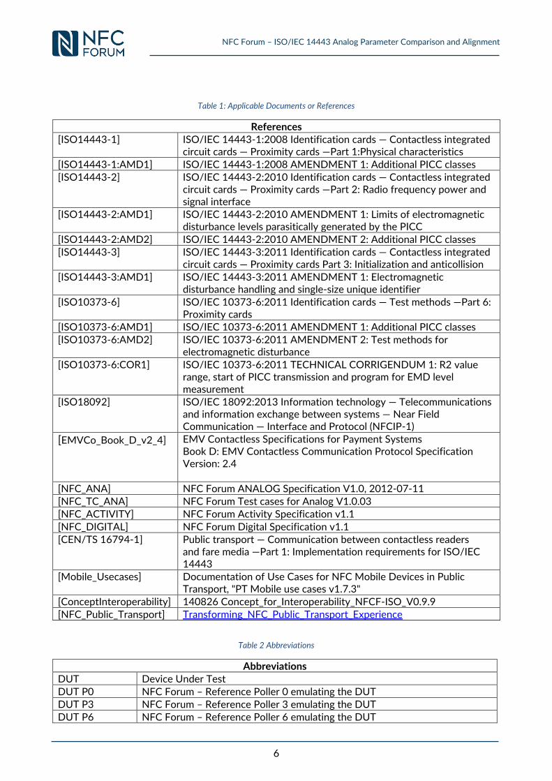
Table 1: Applicable Documents or References
References [ISO14443-1] ISO/IEC 14443-1:2008 Identification cards — Contactless integrated
circuit cards — Proximity cards —Part 1:Physical characteristics
[ISO14443-1:AMD1] ISO/IEC 14443-1:2008 AMENDMENT 1: Additional PICC classes [ISO14443-2] ISO/IEC 14443-2:2010 Identification cards — Contactless integrated
circuit cards — Proximity cards —Part 2: Radio frequency power and signal interface
[ISO14443-2:AMD1] ISO/IEC 14443-2:2010 AMENDMENT 1: Limits of electromagnetic disturbance levels parasitically generated by the PICC
[ISO14443-2:AMD2] ISO/IEC 14443-2:2010 AMENDMENT 2: Additional PICC classes [ISO14443-3] ISO/IEC 14443-3:2011 Identification cards — Contactless integrated
circuit cards — Proximity cards Part 3: Initialization and anticollision [ISO14443-3:AMD1] ISO/IEC 14443-3:2011 AMENDMENT 1: Electromagnetic
disturbance handling and single-size unique identifier
[ISO10373-6] ISO/IEC 10373-6:2011 Identification cards — Test methods —Part 6: Proximity cards
[ISO10373-6:AMD1] ISO/IEC 10373-6:2011 AMENDMENT 1: Additional PICC classes [ISO10373-6:AMD2] ISO/IEC 10373-6:2011 AMENDMENT 2: Test methods for
electromagnetic disturbance
[ISO10373-6:COR1] ISO/IEC 10373-6:2011 TECHNICAL CORRIGENDUM 1: R2 value range, start of PICC transmission and program for EMD level measurement
[ISO18092] ISO/IEC 18092:2013 Information technology — Telecommunications and information exchange between systems — Near Field Communication — Interface and Protocol (NFCIP-1)
[EMVCo_Book_D_v2_4] EMV Contactless Specifications for Payment Systems Book D: EMV Contactless Communication Protocol Specification Version: 2.4
[NFC_ANA] NFC Forum ANALOG Specification V1.0, 2012-07-11 [NFC_TC_ANA] NFC Forum Test cases for Analog V1.0.03 [NFC_ACTIVITY] NFC Forum Activity Specification v1.1
[NFC_DIGITAL] NFC Forum Digital Specification v1.1 [CEN/TS 16794-1] Public transport ― Communication between contactless readers
and fare media ―Part 1: Implementation requirements for ISO/IEC 14443
[Mobile_Usecases] Documentation of Use Cases for NFC Mobile Devices in Public Transport, "PT Mobile use cases v1.7.3"
[ConceptInteroperability] 140826 Concept_for_Interoperability_NFCF-ISO_V0.9.9 [NFC_Public_Transport] Transforming_NFC_Public_Transport_Experience
Table 2 Abbreviations
Abbreviations DUT Device Under Test
DUT P0 NFC Forum – Reference Poller 0 emulating the DUT DUT P3 NFC Forum – Reference Poller 3 emulating the DUT DUT P6 NFC Forum – Reference Poller 6 emulating the DUT
NFC Forum – ISO/IEC 14443 Analog Parameter Comparison and Alignment
7
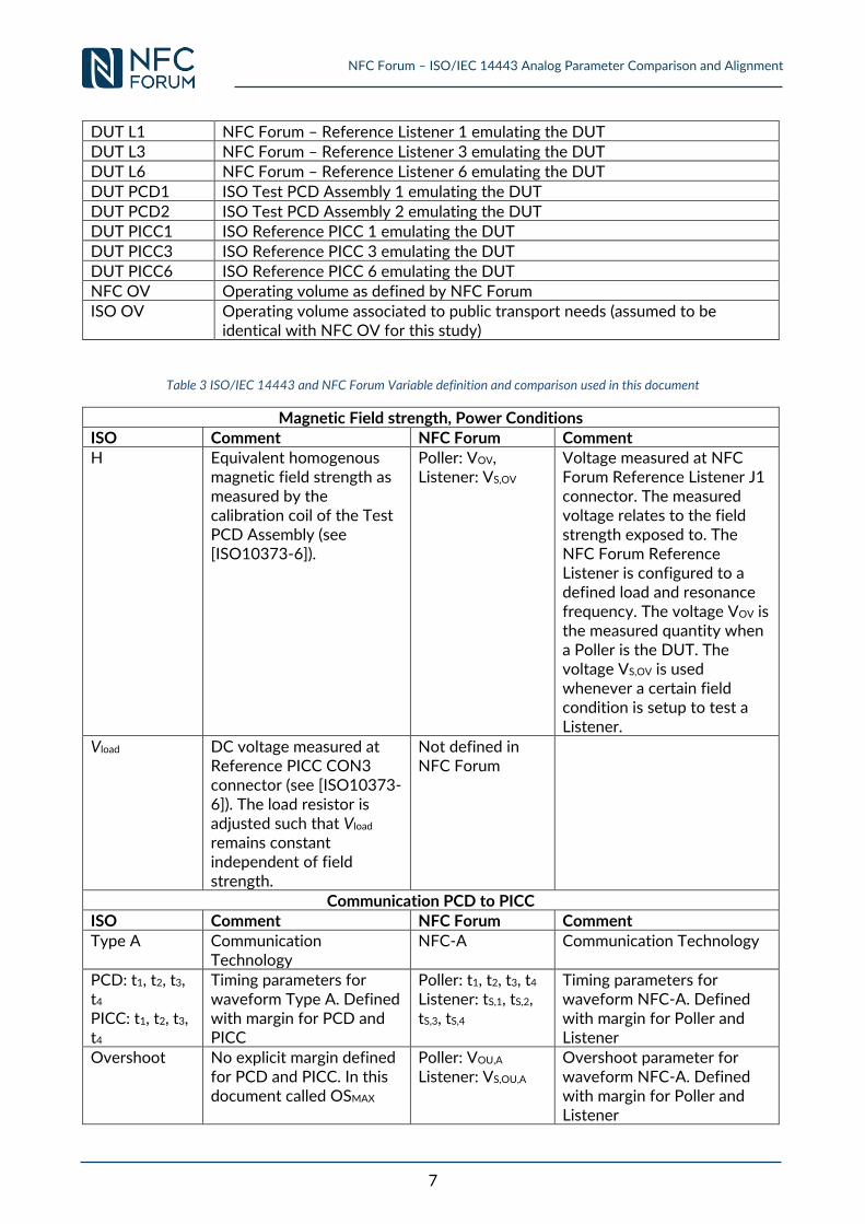
DUT L1 NFC Forum – Reference Listener 1 emulating the DUT DUT L3 NFC Forum – Reference Listener 3 emulating the DUT DUT L6 NFC Forum – Reference Listener 6 emulating the DUT
DUT PCD1 ISO Test PCD Assembly 1 emulating the DUT DUT PCD2 ISO Test PCD Assembly 2 emulating the DUT DUT PICC1 ISO Reference PICC 1 emulating the DUT
DUT PICC3 ISO Reference PICC 3 emulating the DUT DUT PICC6 ISO Reference PICC 6 emulating the DUT NFC OV Operating volume as defined by NFC Forum
ISO OV Operating volume associated to public transport needs (assumed to be identical with NFC OV for this study)
Table 3 ISO/IEC 14443 and NFC Forum Variable definition and comparison used in this document
Magnetic Field strength, Power Conditions ISO Comment NFC Forum Comment H Equivalent homogenous
magnetic field strength as measured by the calibration coil of the Test PCD Assembly (see [ISO10373-6]).
Poller: VOV, Listener: VS,OV
Voltage measured at NFC Forum Reference Listener J1 connector. The measured voltage relates to the field strength exposed to. The NFC Forum Reference Listener is configured to a defined load and resonance frequency. The voltage VOV is the measured quantity when a Poller is the DUT. The voltage VS,OV is used whenever a certain field condition is setup to test a Listener.
Vload DC voltage measured at Reference PICC CON3 connector (see [ISO10373-6]). The load resistor is adjusted such that Vload remains constant independent of field strength.
Not defined in NFC Forum
Communication PCD to PICC ISO Comment NFC Forum Comment
Type A Communication Technology
NFC-A Communication Technology
PCD: t1, t2, t3, t4
PICC: t1, t2, t3, t4
Timing parameters for waveform Type A. Defined with margin for PCD and PICC
Poller: t1, t2, t3, t4 Listener: tS,1, tS,2, tS,3, tS,4
Timing parameters for waveform NFC-A. Defined with margin for Poller and Listener
Overshoot No explicit margin defined for PCD and PICC. In this document called OSMAX
Poller: VOU,A
Listener: VS,OU,A Overshoot parameter for waveform NFC-A. Defined with margin for Poller and Listener
NFC Forum – ISO/IEC 14443 Analog Parameter Comparison and Alignment
8
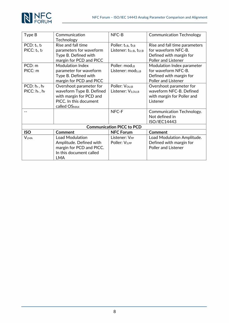
Type B Communication Technology
NFC-B Communication Technology
PCD: tr, tf PICC: tr, tf
Rise and fall time parameters for waveform Type B. Defined with margin for PCD and PICC
Poller: tr,B, tf,B
Listener: tS,r,B, tS,f,B Rise and fall time parameters for waveform NFC-B. Defined with margin for Poller and Listener
PCD: m PICC: m
Modulation Index parameter for waveform Type B. Defined with margin for PCD and PICC
Poller: modi,B
Listener: modS,i,B Modulation Index parameter for waveform NFC-B. Defined with margin for Poller and Listener
PCD: hr , hf
PICC: hr , hf
Overshoot parameter for waveform Type B. Defined with margin for PCD and PICC. In this document called OSMAX
Poller: VOU,B
Listener: VS,OU,B Overshoot parameter for waveform NFC-B. Defined with margin for Poller and Listener
-- NFC-F Communication Technology. Not defined in ISO/IEC14443
Communication PICC to PCD
ISO Comment NFC Forum Comment VLMA Load Modulation
Amplitude. Defined with margin for PCD and PICC. In this document called LMA
Listener: VPP
Poller: VS,PP Load Modulation Amplitude. Defined with margin for Poller and Listener
NFC Forum – ISO/IEC 14443 Analog Parameter Comparison and Alignment
9
1 Introduction
1.1 Motivation and Objectives
The 13.56 MHz contactless interface enables the communication between a Reader and a Card in
close proximity of a distance up to 10 cm. Due to the properties of this interface it is well suited for
applications like payment, public transport, fare collection, ticketing and access control.
Traditionally these applications have been well separated and used in its own closed ecosystem. For
each of the above mentioned applications different standardization bodies emerged and defined
requirements. ISO/IEC 14443 standard series defines the 13.56 MHz interface for applications like
access control, fare collection and ticketing. EMVCo defines the 13.56 MHz radio for payment
applications. ISO/IEC 18092 standard the first time defined requirements for the communication
between mobile devices, known as peer to peer communication, using 13.56 MHz contactless
interface. NFC Forum, an industry association, defined requirements to combine peer to peer,
reader and card functionality in a single device. Therefore NFC Forum defined requirements for this
interface for use within a mobile device. All these developments resulted in an application
dependent fragmentation of the 13.56MHz contactless interface standards.
Over the last years the NFC interface became a standard interface in most smart phones which can
be used for all above mentioned applications and many more. Due to this fact the application
dependent closed ecosystem approach is no longer valid. As a consequence the mobile device has
to be able to interact with readers and/or cards from the above ecosystems. However, each of
them is defining separate requirements for the contactless interface which are similar but not
identical. This fact causes potential interoperability problems which are not in the interest for this
technology and hampers a seamless introduction of mobile use cases into legacy infrastructure.
[Mobile_Usecases] documents relevant mobile use cases in the context of public transport. For this
reason NFC Forum and EMVCo started the harmonization work on digital matters in 2009. In 2014
the scope was extended to the analog parameter gap analysis and harmonization. In parallel NFC
Forum started an initiative of harmonization to ISO/IEC 14443 analog parameters as joint activity
with Public transport organizations, GSMA and ISO JTC1 SC17 WG8 (see also
[NFC_Public_Transport]). WG8 working group defines and maintains amongst others, the
ISO/IEC 14443 standards series.
This document contains a generic comparison of selected analog parameters between NFC Forum
and ISO/IEC 14443. Since the Public Transport use case has a special attention in this work the
application profile defined in [CEN/TS 16794-1] has been taken into account whenever
appropriate. The goal of this work was to define a generic methodology to compare analog
parameter limit values defined by NFC Forum and ISO/IEC 14443. Once parameter limit
differences have been identified concepts and approaches to resolve these differences have been
evaluated with the goal to achieve interoperability.
1.2 Purpose
This document contains the methodology how analog parameters limits between NFC Forum and
ISO/IEC 14443 have been compared. This study takes into account the parameter limits analysis
mapped from NFC Forum to ISO/IEC 14443. For each parameter limit an associated procedure has
NFC Forum – ISO/IEC 14443 Analog Parameter Comparison and Alignment
10
been defined. Each procedure is written in such a way that an experienced engineer can repeat the
procedure and will measure similar results. For parameter limits which resulted in a difference
between NFC Forum and ISO/IEC 14443 an approach for harmonization has been developed. Once
a harmonization solution has been identified, this solution or the resulting candidate parameter
limits have been validated.
1.3 Public Transport Collaborations
This white paper “NFC Forum – ISO/IEC 14443 Analog Parameter Comparison and Alignment”
documents the methodology, procedures and results that have been developed to ensure that
Forum-conformant mobile devices will be interoperable with ISO/IEC14443- and ISO/IEC18092-
conformant public transport readers and objects.
In order to address the needs of the public transport market, NFC Forum’s Transport SIG, in
ollaboration with GSMA, East Japan Railways, CEN TC278 WG3 and the Smart Ticketing Alliance
have identified high level requirements that would need to be fulfilled in order to achieve
interoperability between NFC mobile devices and public transport fare management infrastructures
on a wider scale.
The technical solution addressing these requirements, the “concept for interoperability”,
subsequently has been aligned through a formal liaison between the NFC Forum and CEN TC278
WG3 for ISO/IEC 14443-conformant public transport infrastructures and with East Japan Railways
for ISO/IEC 18092-conformant public transport infrastructures.
As basis for the specification work, the NFC Forum’s Technical Committee then developed the
methodology and procedures for the analog comparison of NFC Forum and ISO/IEC 14443
specifications and discussed the results with CEN TC278 WG3, GSMA, East Japan Railways and
Smart Ticketing Alliance’s experts at the Joint Public Transport Workshops. The result is
documented in this white paper “NFC Forum – ISO/IEC 14443 Analog Parameter Comparison and
Alignment”.
Based on these agreed methods and procedures, the NFC Forum developed version 2.0 of the
Analog Specification which shall be applied to NFC mobile devices which are used for public
transport services. CEN TC278 WG3 generated the 2nd edition of CEN/TS 16794 for public
transport contactless readers and objects. This 2nd edition was enhanced to support
interoperability with NFC mobile devices. Both specifications are synchronized and hence enable
contactless interoperability between NFC mobile devices conformant to NFC Forum’s new Analog
2.0 (or later) specification and existing Activity and Digital specifications, and public transport
readers and objects conformant to the 2nd edition of CEN/TS 16794.
The concept for interoperability and its technical foundation which is documented in this white
paper “NFC Forum – ISO/IEC 14443 Analog Parameter Comparison and Alignment” are formally
endorsed by CEN TC278 WG3.The NFC Forum, ISO/IEC JTC1/SC17/WG8 and CEN TC278 WG3
intend to continue their technical cooperation in order to provide synchronized updates of their
specifications as required.
NFC Forum – ISO/IEC 14443 Analog Parameter Comparison and Alignment
11
1.4 Outline of This Document
Section 2 of this document defines the boundary conditions, the methodology approach used for
the harmonization work and the selected analog parameters. In section 3 the actual parameter limit
comparison is performed. Thus, this part defines the procedures for each selected parameter limit
and the according measurement results. The measurement results provide evidence on potential
limit differences. For parameter limits with identified limit differences the subsequently following
section 4 describes the detail way for harmonization. Afterwards the validation of the
harmonization result is presented. Section 5 defines a way forward how to introduce the analog
EMD requirement in a harmonized manner in NFC Forum. Finally for easy cross reference Annex A
and Annex B contain the relevant requirements defined by ISO/IEC 14443 used for this
harmonization.
NFC Forum – ISO/IEC 14443 Analog Parameter Comparison and Alignment
12
2 Boundary Conditions and Methodology for Analog Parameter Comparison
NFC Forum defines different roles for a mobile device, which are:
Peer: A role either equal to the role of an Initiator (Poller) or to the role of a Target
(Listener).The Peer role covers the peer to peer (P2P) communication between Initiator and
Target.
Reader: NFC Forum Device in Poll Mode when it has gone through a number of Activities.
The Reader covers the communication to Tags and legacy PICCs
Card Emulator (CE): NFC Forum Device in Listen Mode when it has gone through a number
of states. CE covers the communication to legacy infrastructure (Readers or PCDs)
The document [Mobile_Usecases] performs an analysis of mobile use cases in Public Transport. This
analysis shows that the Reader and the Card Emulator role are essential and therefore have to be
supported.
2.1 Interoperability Versus Conformance
At the start of this harmonization activity an analysis was performed if interoperability or
conformance is the goal to be achieved for this project. In order to answer this question a common
understanding of the two terms had been developed. Therefore the following definitions are valid
for interoperability and conformance/compliance in the context of this harmonization work when
comparing requirements between NFC Forum and ISO/IEC 14443.
Conformance/Compliance: An NFC Forum Device implementing a certain set of
requirements which are tested according to NFC Forum would automatically also fulfill
the requirements as defined and tested by ISO/IEC 14443 and [ISO10373-6]. This
results in a perfect match of the requirement and resulting operating range (minimum
and maximum limit of a parameter) including testing and test equipment as defined by
both organizations.
Example: An NFC Forum Device in Reader role tested for load modulation amplitude
reception requirement according to NFC Forum will implicitly fulfill the related PCD
requirement and test according to ISO/IEC 14443 and [ISO10373-6], respectively.
Interoperability: An NFC Forum Device in a certain role (e.g., Reader) implementing a
certain set of requirements which are tested according to NFC Forum would be able to
communicate with the counterpart (e.g., Card) as defined by ISO/IEC 14443. This
counterpart (e.g., Card) implements the requirements as defined and tested by
ISO/IEC 14443 and [ISO10373-6].
Example: An NFC Forum Device in Reader role implementing and tested for load
modulation amplitude requirement according to NFC Forum will be able to communicate
with a PICC implementing the requirement and test according to ISO/IEC 14443.
NOTE Additionally this interoperability definition includes an assessment on relevance for
interoperability in the field. This covers the case of differences on parameter limits which
are declared to be non-critical or irrelevant for interoperability in the field or due to non-
NFC Forum – ISO/IEC 14443 Analog Parameter Comparison and Alignment
13
applicability for the defined use cases in [Mobile_Usecases]. Therefore these differences will
be given low priority, if at all, and are rated as theoretical differences.
The above definition of conformance and interoperability leaded to the conclusion that for this
work interoperability is the primary target to ensure interoperability between NFC Forum
conformant devices and public transport certified reader or media in the field. Nevertheless it was
decided that the parameter limit comparison will address both, interoperability and conformance.
2.2 Boundary Conditions
In order to achieve a valid assessment for parameter limit comparison and their harmonization some
boundary conditions have been defined. The following boundary conditions have been agreed
between NFC Forum Technical Experts, Transport SIG and PT Experts:
1. Operating Volume (OV):
In contrast to NFC Forum, ISO/IEC 14443 standard series do not specify absolute values for
an operating volume (OV). ISO/IEC14443 defines the OV for each PICC class as the
positions where the corresponding Reference PICC shows PCD compliance with all
requirements of this part of ISO/IEC14443. For simplicity the OV as defined by NFC Forum
is assumed to represent the ISO/IEC 14443 and PT OV. This OV definition will be used
throughout this harmonization work. A definition of the OV can be found in [NFC_ANA].
Thus the same OV is valid for the ISO/IEC 14443 as well as the NFC Forum perspective of
requirements.
There is one additional Listening side requirement on the operating distance in [CEN/TS
16794-1] on NFC Forum perspective. The Load Modulation Amplitude (LMA) for NFC
Forum Devices in Listen Mode is required to be valid up to 2 cm in z-direction. Since the
distance aspect is inherently covered by the requirement defined by [ISO14443-2] and its
associated test methods [ISO10373-6] it does not require special analysis.
2. PICC Antenna classes:
A detailed analysis has to be performed in order to carry out a boundary condition definition
on the PICC antenna classes for this harmonization work. [ISO14443-1:AMD1], sec. 5.2.2
defines as mandatory requirement for PCD compliance to support PICCs of "Class 1",
"Class 2" and "Class 3". This requirement is also defined for the public transport use case in
[CEN/TS 16794-1] and described in [Mobile_Usecases]. In order to achieve interoperability
between a mobile device and PT reader or media, an NFC Forum Device in Reader role has
to support the requirements for PICCs of "Class 1", "Class 2" and "Class 3" and a NFC Forum
Device in CE role must behave independently on its antenna size at least as a PICC of
"Class 3". With this analysis we can derive the following antenna class dependent boundary
conditions:
a. An NFC Forum Polling Device claiming ISO compliance has to be compliant to:
Mandatory: Class 1-3 compliance
Optional: Class 1-3 and 6 compliance
Optional: Class 6 only compliance (only for information purposes, not relevant for
use cases)
b. NFC Forum Listening Device claiming ISO compliance has to fulfill the following
requirements:
Optional: Compliance to the particular antenna class
NFC Forum – ISO/IEC 14443 Analog Parameter Comparison and Alignment
14
Mandatory: Compliance to either of Class 1 to 3
2.2.1 Generic Considerations on the Antenna Size and Its Impact on
Communication Stability
The 13.56 MHz radio performs communication and/or power transfer using magnetic coupling.
Generally, the ratio of the Reader to Card antenna size as well as their relative distance determines
the coupling. This has a huge impact on both, communication stability and power transfer.
One can mainly distinguish between the two extreme cases of coupling:
Low coupling and high coupling cases:
o Low coupling is encountered in cases of large antenna size differences or at
large distance between Reader and Card antennas.
o High coupling situations are met in case of almost equal antenna sizes of
Reader and Card and at small distances between the antennas.
As described in the introduction, in the past Readers and Cards have been primary designed for
single applications used in a closed ecosystem. Public transport and Payment clearly belong to these
applications and implemented systems mainly based on the low coupling case. In contrast access
systems and the communication between mobile phones are mainly designed for the high coupling
case. Due to the increasing mobile phone multi-application usage covering public transport as well
as payment the mobile use case faces new challenges. It has to support both, low and high coupling
cases which finally will impact all, Readers, Cards and mobile devices.
2.3 Methodology
For the analog limit comparison between EMVCo and NFC Forum a methodology was developed.
This methodology will be equally followed in this work.
Parameter limits comparison can be carried out either from NFC Forum to ISO/IEC 14443 or from
ISO/IEC 14443 to NFC Forum. The term NFC Forum perspective denotes the parameter
comparison from NFC Forum to ISO/IEC 14443 and ISO/IEC perspective denotes the comparison
from ISO/IEC 14443 to NFC Forum. Depending on the mentioned perspective the Device under
Test (DUT) is emulated by the according reference equipment. This study considers only the NFC
Forum perspective.
1. ISO/IEC perspective, PCD and PICC requirements:
Test PCD Assembly 1 and 2 [ISO10373-6], [ISO10373-6:AMD1] are used to emulate
the PCD Device Under Test (DUT)
ISO/IEC Reference PICC 1, 2, 3 and 6 are used to emulate the DUT PICCs
2. NFC Forum perspective, Poller and Listener requirements:
NFC Forum – Reference Pollers 0, 3 and 6 are used to emulate the DUT Poller
NFC Forum – Reference Listeners 1, 3 and 6 are used to emulate the DUT Listener
Once the setup for a certain test condition has been performed these DUTs can be evaluated in the environment of interest. Compliance and interoperability between the standards is tested by the following fundamental principle:
NFC Forum – ISO/IEC 14443 Analog Parameter Comparison and Alignment
15
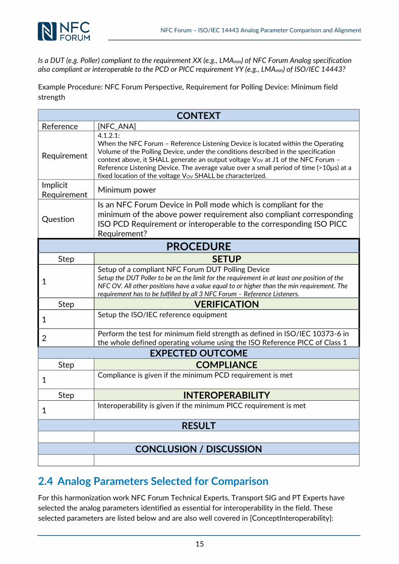
Is a DUT (e.g. Poller) compliant to the requirement XX (e.g., LMAmin) of NFC Forum Analog specification also compliant or interoperable to the PCD or PICC requirement YY (e.g., LMAmin) of ISO/IEC 14443? Example Procedure: NFC Forum Perspective, Requirement for Polling Device: Minimum field
strength
CONTEXT
Reference [NFC_ANA]
Requirement
4.1.2.1: When the NFC Forum – Reference Listening Device is located within the Operating Volume of the Polling Device, under the conditions described in the specification context above, it SHALL generate an output voltage VOV at J1 of the NFC Forum – Reference Listening Device. The average value over a small period of time (>10μs) at a fixed location of the voltage VOV SHALL be characterized.
Implicit Requirement
Minimum power
Question
Is an NFC Forum Device in Poll mode which is compliant for the minimum of the above power requirement also compliant corresponding ISO PCD Requirement or interoperable to the corresponding ISO PICC Requirement?
PROCEDURE Step SETUP
1
Setup of a compliant NFC Forum DUT Polling Device Setup the DUT Poller to be on the limit for the requirement in at least one position of the NFC OV. All other positions have a value equal to or higher than the min requirement. The requirement has to be fulfilled by all 3 NFC Forum – Reference Listeners.
Step VERIFICATION
1 Setup the ISO/IEC reference equipment
2 Perform the test for minimum field strength as defined in ISO/IEC 10373-6 in the whole defined operating volume using the ISO Reference PICC of Class 1
EXPECTED OUTCOME
Step COMPLIANCE
1 Compliance is given if the minimum PCD requirement is met
Step INTEROPERABILITY
1 Interoperability is given if the minimum PICC requirement is met
RESULT
CONCLUSION / DISCUSSION
2.4 Analog Parameters Selected for Comparison
For this harmonization work NFC Forum Technical Experts, Transport SIG and PT Experts have
selected the analog parameters identified as essential for interoperability in the field. These
selected parameters are listed below and are also well covered in [ConceptInteroperability]:
NFC Forum – ISO/IEC 14443 Analog Parameter Comparison and Alignment
16
1. Bit rates considered:
ISO/IEC 14443 – NFC Forum: 106 kbps (Type A and Type B), for both communication
directions
ISO/IEC 18092 – NFC Forum (passive communication mode only):
For analog parameter and its limit ISO/IEC 18092 references to ISO/IEC 14443.
o NFC-A: 106 kbps, for both communication directions (covered by ISO/IEC 14443
– NFC Forum)
o NFC-F: 212 and 424 kbps, for both communication directions (covered by
ISO/IEC 14443 – NFC Forum)
Poller - Listener communication direction: analog parameter are covered
by NFC-B Technology analysis
Listener – Poller communication direction: analog parameter are covered
by generic LMA analysis
2. Magnetic field strength:
Minimum and maximum magnetic field strength
Maximum alternating field strength according to [ISO14443-1]
3. Electromagnetic disturbance
4. Maximum loading effect / Influence on the field
5. Resetting the operating field (VOV,RESET)
6. Waveform transmission/reception (PCD-PICC / Poller-Listener)
7. Load modulation transmission/reception (PICC-PCD / Listener-Poller)
NFC Forum – ISO/IEC 14443 Analog Parameter Comparison and Alignment
17
3 NFC Forum to ISO/IEC 14443 Comparison (NFC Forum Perspective)
This section contains the analog parameter comparison procedures defined for each parameter
limit. Below each procedure description, the measurement results are presented. Generally, results
are shown once to address the compliance aspect and once the interoperability aspect. Following
the measurement results a verdict assessment is performed. First the status quo assessment for the
Polling Device is carried out
3.1 Polling Device Requirements
This section contains the procedure and comparison results for the following parameter limits:
Power Transfer from Polling Device to Listening Device (Polling Device Transmission)
o Minimum field strength
o Maximum field strength
Listening Device Reset (Polling Device Transmission)
Polling Device RF Collision Avoidance before Carrier Generation
Modulation Polling Device to Listening Device – NFC-A (Polling Device Transmission)
o Waveform Analysis
o Overshoot and Undershoot analysis
Modulation Polling Device to Listening Device – NFC-B (Polling Device Transmission)
Modulation Listening Device to Polling Device (Polling Device Reception)
o Minimum load modulation amplitude
o Maximum load modulation amplitude
3.1.1 Requirement 4.1.2.1: Power Transfer from Polling Device to Listening
Device (Polling Device Transmission)
a. Minimum field strength
CONTEXT
Reference [NFC_ANA]
Requirement 4.1.2.1: When the NFC Forum – Reference Listening Device is located within the Operating Volume of the Polling Device, under the conditions described in the specification context above, it SHALL generate an output voltage VOV at J1 of the NFC Forum – Reference Listening Device. The average value over a small period of time (>10μs) at a fixed location of the voltage VOV SHALL be characterized.
Implicit Requirement
Minimum power
Question Is an NFC Forum Device in Poll mode which is compliant for the minimum of the above power requirement also compliant or interoperable to the corresponding ISO PCD Requirement?
NFC Forum – ISO/IEC 14443 Analog Parameter Comparison and Alignment
18
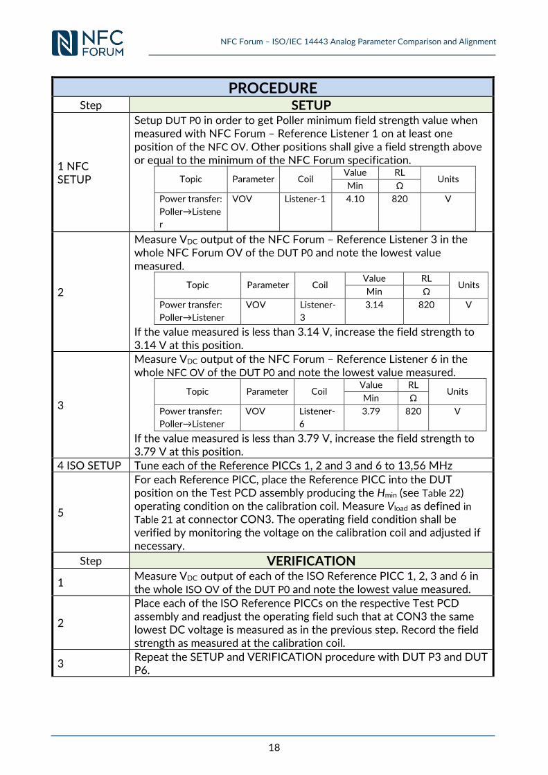
PROCEDURE Step SETUP
1 NFC SETUP
Setup DUT P0 in order to get Poller minimum field strength value when measured with NFC Forum – Reference Listener 1 on at least one position of the NFC OV. Other positions shall give a field strength above or equal to the minimum of the NFC Forum specification.
Topic Parameter Coil Value RL
Units Min Ω
Power transfer:
Poller→Listene
r
VOV Listener-1 4.10 820 V
2
Measure VDC output of the NFC Forum – Reference Listener 3 in the whole NFC Forum OV of the DUT P0 and note the lowest value measured.
Topic Parameter Coil Value RL
Units Min Ω
Power transfer:
Poller→Listener
VOV Listener-
3
3.14 820 V
If the value measured is less than 3.14 V, increase the field strength to 3.14 V at this position.
3
Measure VDC output of the NFC Forum – Reference Listener 6 in the whole NFC OV of the DUT P0 and note the lowest value measured.
Topic Parameter Coil Value RL
Units Min Ω
Power transfer:
Poller→Listener
VOV Listener-
6
3.79 820 V
If the value measured is less than 3.79 V, increase the field strength to 3.79 V at this position.
4 ISO SETUP Tune each of the Reference PICCs 1, 2 and 3 and 6 to 13,56 MHz
5
For each Reference PICC, place the Reference PICC into the DUT position on the Test PCD assembly producing the Hmin (see Table 22) operating condition on the calibration coil. Measure Vload as defined in
Table 21 at connector CON3. The operating field condition shall be verified by monitoring the voltage on the calibration coil and adjusted if necessary.
Step VERIFICATION
1 Measure VDC output of each of the ISO Reference PICC 1, 2, 3 and 6 in the whole ISO OV of the DUT P0 and note the lowest value measured.
2
Place each of the ISO Reference PICCs on the respective Test PCD assembly and readjust the operating field such that at CON3 the same lowest DC voltage is measured as in the previous step. Record the field strength as measured at the calibration coil.
3 Repeat the SETUP and VERIFICATION procedure with DUT P3 and DUT P6.
NFC Forum – ISO/IEC 14443 Analog Parameter Comparison and Alignment
19
EXPECTED OUTCOME
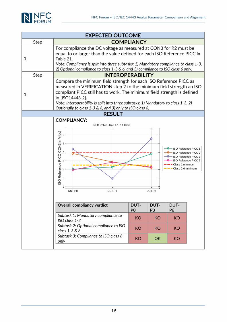
Step COMPLIANCY
1
For compliance the DC voltage as measured at CON3 for R2 must be equal to or larger than the value defined for each ISO Reference PICC in Table 21. Note: Compliancy is split into three subtasks: 1) Mandatory compliance to class 1-3, 2) Optional compliance to class 1-3 & 6, and 3) compliance to ISO class 6 only.
Step INTEROPERABILITY
1
Compare the minimum field strength for each ISO Reference PICC as measured in VERIFICATION step 2 to the minimum field strength an ISO compliant PICC still has to work. The minimum field strength is defined in [ISO14443-2]. Note: Interoperability is split into three subtasks: 1) Mandatory to class 1-3, 2) Optionally to class 1-3 & 6, and 3) only to ISO class 6.
RESULT
COMPLIANCY:
Overall compliancy verdict DUT-P0
DUT-P3
DUT-P6
Subtask 1: Mandatory compliance to ISO class 1-3
KO KO KO
Subtask 2: Optional compliance to ISO class 1-3 & 6
KO KO KO
Subtask 3: Compliance to ISO class 6 only
KO OK KO
DUT-P0 DUT-P3 DUT-P6
2
3
4
5
6
7
8
ISO
Re
fere
nce
PIC
C C
ON
3 in
V(d
c)
NFC Poller - Req 4.1.2.1 Hmin
ISO Reference PICC 1
ISO Reference PICC 2
ISO Reference PICC 3
ISO Reference PICC 6
Class 1 minimum
Class 2-6 minimum
NFC Forum – ISO/IEC 14443 Analog Parameter Comparison and Alignment
20
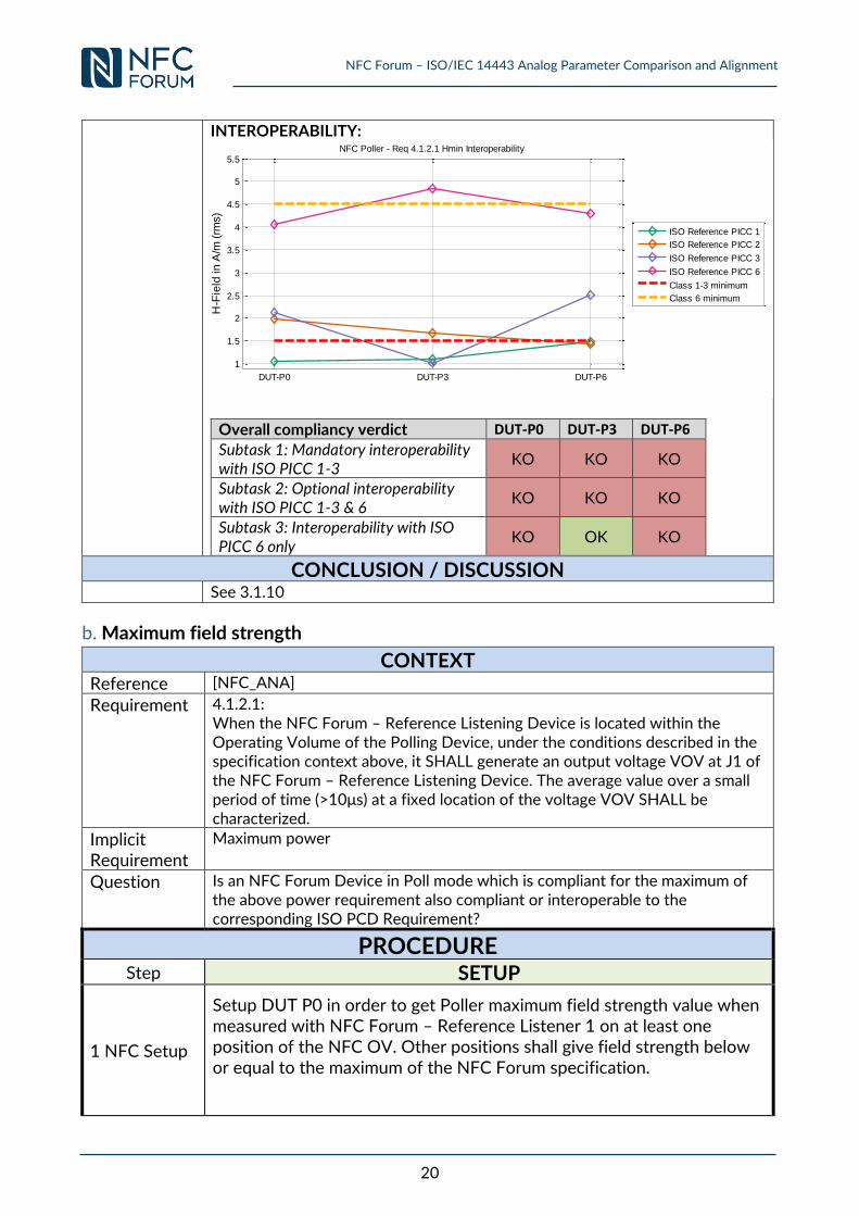
INTEROPERABILITY:
Overall compliancy verdict DUT-P0 DUT-P3 DUT-P6
Subtask 1: Mandatory interoperability with ISO PICC 1-3
KO KO KO
Subtask 2: Optional interoperability with ISO PICC 1-3 & 6
KO KO KO
Subtask 3: Interoperability with ISO PICC 6 only
KO OK KO
CONCLUSION / DISCUSSION
See 3.1.10
b. Maximum field strength
CONTEXT
Reference [NFC_ANA]
Requirement 4.1.2.1: When the NFC Forum – Reference Listening Device is located within the Operating Volume of the Polling Device, under the conditions described in the specification context above, it SHALL generate an output voltage VOV at J1 of the NFC Forum – Reference Listening Device. The average value over a small period of time (>10μs) at a fixed location of the voltage VOV SHALL be characterized.
Implicit Requirement
Maximum power
Question Is an NFC Forum Device in Poll mode which is compliant for the maximum of the above power requirement also compliant or interoperable to the corresponding ISO PCD Requirement?
PROCEDURE Step SETUP
1 NFC Setup
Setup DUT P0 in order to get Poller maximum field strength value when measured with NFC Forum – Reference Listener 1 on at least one position of the NFC OV. Other positions shall give field strength below or equal to the maximum of the NFC Forum specification.
DUT-P0 DUT-P3 DUT-P6
1
1.5
2
2.5
3
3.5
4
4.5
5
5.5
H-F
ield
in
A/m
(rm
s)
NFC Poller - Req 4.1.2.1 Hmin Interoperability
ISO Reference PICC 1
ISO Reference PICC 2
ISO Reference PICC 3
ISO Reference PICC 6
Class 1-3 minimum
Class 6 minimum
NFC Forum – ISO/IEC 14443 Analog Parameter Comparison and Alignment
21
Topic Parameter Coil Value RL
Units Max Ω
Power transfer:
Poller→Listener VOV Listener-1 2.85 82 V
2
Measure VDC output of the NFC Forum – Reference Listener 3 in the whole NFC OV of the DUT P0 and note the highest value measured.
Topic Parameter Coil Value RL
Units Max Ω
Power transfer:
Poller→Listener VOV Listener-
3 2.30 82 V
If the value measured is more than 2.30 V, decrease the field strength to 2.30 V at this position.
3
Measure VDC output of the NFC Forum – Reference Listener 6 in the whole NFC OV of the DUT P0 and note the highest value measured.
Topic Parameter Coil Value RL
Units Max Ω
Power transfer:
Poller→Listener VOV Listener-6 2.23 82 V
If the value measured is more than 2.23 V, decrease the field strength to 2.23 V at this position.
4 Repeat above SETUP procedure with DUT P3 and DUT P6
5 ISO Setup Tune fres of each of the ISO Reference PICC 1, 2, 3 and 6 to 19 MHz.
6 Calibrate the ISO Test PCD assembly to produce the Hmax (see Table 22) operating condition on the calibration coil.
7
Place each ISO Reference PICC into the DUT position on the Test PCD assembly. Adjust R2 to obtain a DC voltage of 3 V measured at connector CON3. The operating field condition shall be verified by monitoring the voltage on the calibration coil and adjusted if necessary.
Step VERIFICATION
1 Measure VDC output of each ISO Reference PICC in the whole ISO OV of the DUT P0 and note the highest value measured.
2
Place each of the ISO Reference PICCs on the respective Test PCD assembly and readjust the operating field such that at CON3 the same highest DC voltage is measured as in the previous step. Record the field strength as measure at the calibration coil.
3 Repeat above VERIFICATION procedure with DUT P3 and DUT P6.
EXPECTED OUTCOME
Step COMPLIANCY
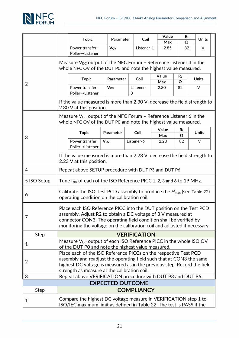
1 Compare the highest DC voltage measure in VERIFICATION step 1 to ISO/IEC maximum limit as defined in Table 22. The test is PASS if the
NFC Forum – ISO/IEC 14443 Analog Parameter Comparison and Alignment
22
measured DC voltage of VERIFICATION step 1 is lower than the value in Table 22.
Note: Compliancy is split into three subtasks: 1) Mandatory compliance to class 1-3, and 2) Optional compliance to class 1-3 & 6 3) compliance to ISO class 6.
Step INTEROPERABILITY
1
Compare the maximum measured H-field strength of VERIFICATION step 2 to the limit an ISO compliant PICC must be able to be functional (see Annex 0, clause 0, [ISO14443-2]). Note: Interoperability is split into three subtasks: 1) Mandatory to class 1-3, and 2) Optionally to class 1-3 & 6 3) only to ISO class 6.
RESULT
COMPLIANCY:
Verdict assessment: PASS if below the ISO/IEC 14443 defined limit curve.
Overall compliancy verdict DUT-P0
DUT-P3
DUT-P6
Subtask 1: Mandatory compliance to ISO class 1-3
KO OK OK
Subtask 2: Optional compliance to ISO class 1-3 & 6
KO OK OK
Subtask 3: Compliance to ISO class 6 only
OK OK OK
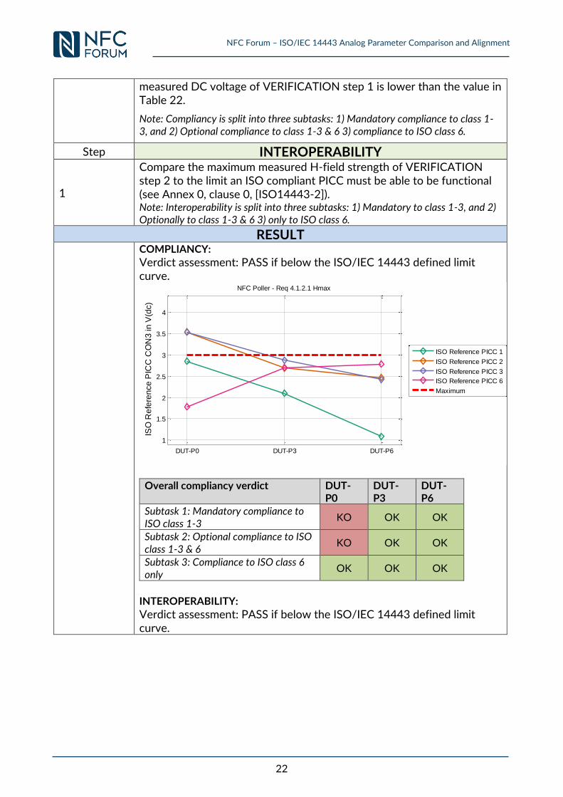
INTEROPERABILITY:
Verdict assessment: PASS if below the ISO/IEC 14443 defined limit curve.
DUT-P0 DUT-P3 DUT-P6
1
1.5
2
2.5
3
3.5
4
ISO
Re
fere
nce
PIC
C C
ON
3 in
V(d
c)
NFC Poller - Req 4.1.2.1 Hmax
ISO Reference PICC 1
ISO Reference PICC 2
ISO Reference PICC 3
ISO Reference PICC 6
Maximum
NFC Forum – ISO/IEC 14443 Analog Parameter Comparison and Alignment
23
Overall interoperability verdict DUT-P0
DUT-P3
DUT-P6
Subtask 1: Mandatory interoperability with ISO PICC 1-3
KO OK OK
Subtask 2: Optional interoperability with ISO PICC 1-3 & 6
KO OK OK
Subtask 3: Interoperability with ISO PICC 6 only
OK OK OK
CONCLUSION / DISCUSSION
See 3.1.10
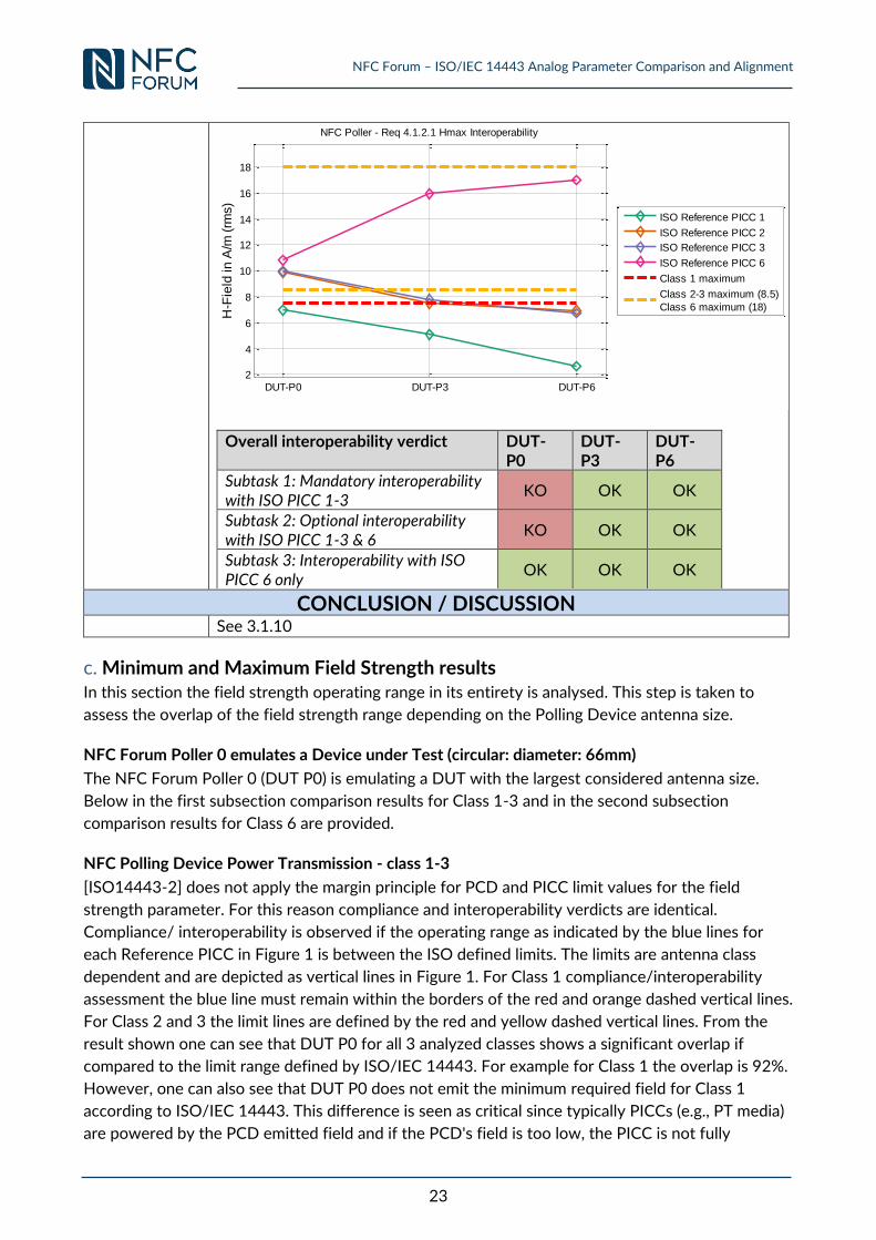
c. Minimum and Maximum Field Strength results In this section the field strength operating range in its entirety is analysed. This step is taken to
assess the overlap of the field strength range depending on the Polling Device antenna size.
NFC Forum Poller 0 emulates a Device under Test (circular: diameter: 66mm)
The NFC Forum Poller 0 (DUT P0) is emulating a DUT with the largest considered antenna size.
Below in the first subsection comparison results for Class 1-3 and in the second subsection
comparison results for Class 6 are provided.
NFC Polling Device Power Transmission - class 1-3
[ISO14443-2] does not apply the margin principle for PCD and PICC limit values for the field
strength parameter. For this reason compliance and interoperability verdicts are identical.
Compliance/ interoperability is observed if the operating range as indicated by the blue lines for
each Reference PICC in Figure 1 is between the ISO defined limits. The limits are antenna class
dependent and are depicted as vertical lines in Figure 1. For Class 1 compliance/interoperability
assessment the blue line must remain within the borders of the red and orange dashed vertical lines.
For Class 2 and 3 the limit lines are defined by the red and yellow dashed vertical lines. From the
result shown one can see that DUT P0 for all 3 analyzed classes shows a significant overlap if
compared to the limit range defined by ISO/IEC 14443. For example for Class 1 the overlap is 92%.
However, one can also see that DUT P0 does not emit the minimum required field for Class 1
according to ISO/IEC 14443. This difference is seen as critical since typically PICCs (e.g., PT media)
are powered by the PCD emitted field and if the PCD's field is too low, the PICC is not fully
DUT-P0 DUT-P3 DUT-P62
4
6
8
10
12
14
16
18
H-F
ield
in
A/m
(rm
s)
NFC Poller - Req 4.1.2.1 Hmax Interoperability
ISO Reference PICC 1
ISO Reference PICC 2
ISO Reference PICC 3
ISO Reference PICC 6
Class 1 maximum
Class 2-3 maximum (8.5)
Class 6 maximum (18)
NFC Forum – ISO/IEC 14443 Analog Parameter Comparison and Alignment
24
powered and therefore no communication is possible. In contrast, for Class 2 and 3 the maximum
power requirement is exceeded. This difference has been rated as insignificant for the following
reasons:
Mobile Phones are battery powered and therefore do not emit a field close to the maximum.
The field in both cases is below the maximum alternating field strength defined in
[ISO14443-1] and [ISO14443-1:AMD1] a PICC has to permanently survive if exposed to.
For the maximum field strength the Reference PICCs are configured to the lowest load
possible. Any known PICC deployed in the field has a loading higher than the Reference
PICC and this would result in a lower field strength observed by the PICC.
Figure 1: DUT Poller 0 field strength parameter comparison for Class 1-3 compliance/interoperability assessment.
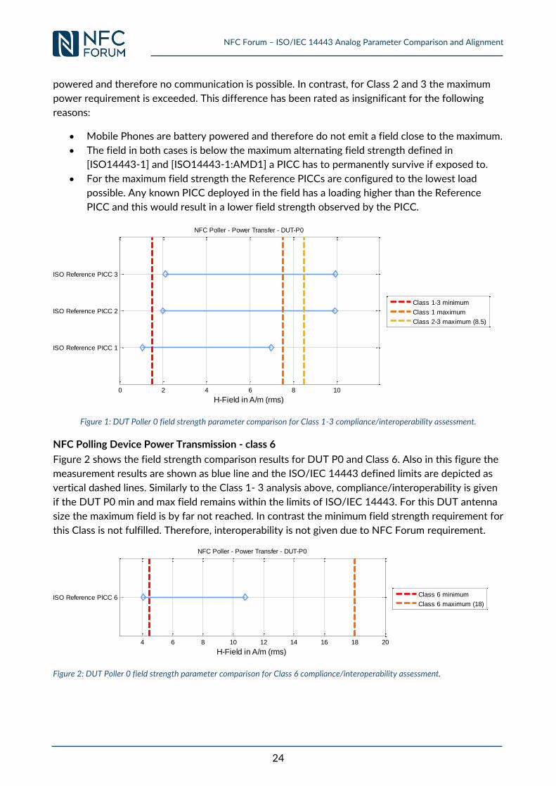
NFC Polling Device Power Transmission - class 6
Figure 2 shows the field strength comparison results for DUT P0 and Class 6. Also in this figure the
measurement results are shown as blue line and the ISO/IEC 14443 defined limits are depicted as
vertical dashed lines. Similarly to the Class 1- 3 analysis above, compliance/interoperability is given
if the DUT P0 min and max field remains within the limits of ISO/IEC 14443. For this DUT antenna
size the maximum field is by far not reached. In contrast the minimum field strength requirement for
this Class is not fulfilled. Therefore, interoperability is not given due to NFC Forum requirement.
Figure 2: DUT Poller 0 field strength parameter comparison for Class 6 compliance/interoperability assessment.
0 2 4 6 8 10
ISO Reference PICC 1
ISO Reference PICC 2
ISO Reference PICC 3
H-Field in A/m (rms)
NFC Poller - Power Transfer - DUT-P0
Class 1-3 minimum
Class 1 maximum
Class 2-3 maximum (8.5)
4 6 8 10 12 14 16 18 20
ISO Reference PICC 6
H-Field in A/m (rms)
NFC Poller - Power Transfer - DUT-P0
Class 6 minimum
Class 6 maximum (18)
NFC Forum – ISO/IEC 14443 Analog Parameter Comparison and Alignment
25
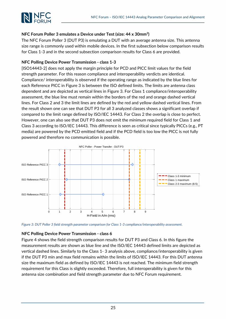
NFC Forum Poller 3 emulates a Device under Test (size: 44 x 30mm2)
The NFC Forum Poller 3 (DUT P3) is emulating a DUT with an average antenna size. This antenna
size range is commonly used within mobile devices. In the first subsection below comparison results
for Class 1-3 and in the second subsection comparison results for Class 6 are provided.
NFC Polling Device Power Transmission - class 1-3
[ISO14443-2] does not apply the margin principle for PCD and PICC limit values for the field
strength parameter. For this reason compliance and interoperability verdicts are identical.
Compliance/ interoperability is observed if the operating range as indicated by the blue lines for
each Reference PICC in Figure 3 is between the ISO defined limits. The limits are antenna class
dependent and are depicted as vertical lines in Figure 3. For Class 1 compliance/interoperability
assessment, the blue line must remain within the borders of the red and orange dashed vertical
lines. For Class 2 and 3 the limit lines are defined by the red and yellow dashed vertical lines. From
the result shown one can see that DUT P3 for all 3 analyzed classes shows a significant overlap if
compared to the limit range defined by ISO/IEC 14443. For Class 2 the overlap is close to perfect.
However, one can also see that DUT P3 does not emit the minimum required field for Class 1 and
Class 3 according to ISO/IEC 14443. This difference is seen as critical since typically PICCs (e.g., PT
media) are powered by the PCD emitted field and if the PCD field is too low the PICC is not fully
powered and therefore no communication is possible.
Figure 3: DUT Poller 3 field strength parameter comparison for Class 1-3 compliance/interoperability assessment.
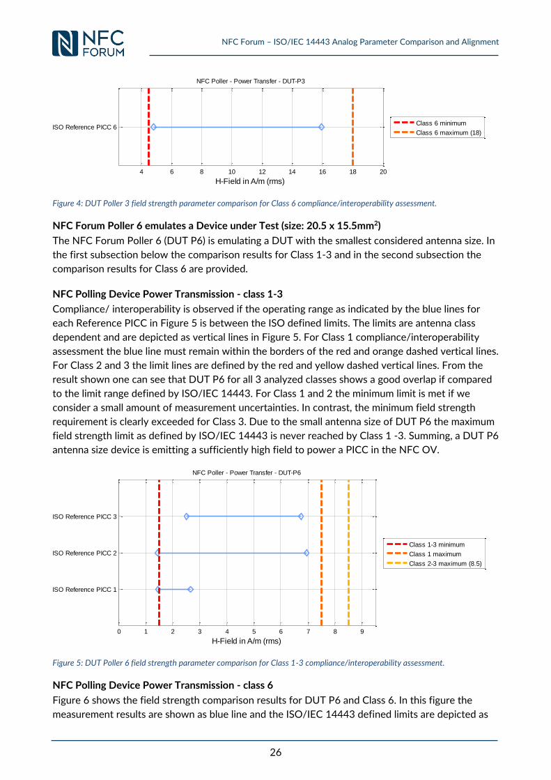
NFC Polling Device Power Transmission - class 6
Figure 4 shows the field strength comparison results for DUT P3 and Class 6. In this figure the
measurement results are shown as blue line and the ISO/IEC 14443 defined limits are depicted as
vertical dashed lines. Similarly to the Class 1- 3 analysis above, compliance/interoperability is given
if the DUT P3 min and max field remains within the limits of ISO/IEC 14443. For this DUT antenna
size the maximum field as defined by ISO/IEC 14443 is not reached. The minimum field strength
requirement for this Class is slightly exceeded. Therefore, full interoperability is given for this
antenna size combination and field strength parameter due to NFC Forum requirement.
0 1 2 3 4 5 6 7 8 9
ISO Reference PICC 1
ISO Reference PICC 2
ISO Reference PICC 3
H-Field in A/m (rms)
NFC Poller - Power Transfer - DUT-P3
Class 1-3 minimum
Class 1 maximum
Class 2-3 maximum (8.5)
NFC Forum – ISO/IEC 14443 Analog Parameter Comparison and Alignment
26
Figure 4: DUT Poller 3 field strength parameter comparison for Class 6 compliance/interoperability assessment.
NFC Forum Poller 6 emulates a Device under Test (size: 20.5 x 15.5mm2)
The NFC Forum Poller 6 (DUT P6) is emulating a DUT with the smallest considered antenna size. In
the first subsection below the comparison results for Class 1-3 and in the second subsection the
comparison results for Class 6 are provided.
NFC Polling Device Power Transmission - class 1-3
Compliance/ interoperability is observed if the operating range as indicated by the blue lines for
each Reference PICC in Figure 5 is between the ISO defined limits. The limits are antenna class
dependent and are depicted as vertical lines in Figure 5. For Class 1 compliance/interoperability
assessment the blue line must remain within the borders of the red and orange dashed vertical lines.
For Class 2 and 3 the limit lines are defined by the red and yellow dashed vertical lines. From the
result shown one can see that DUT P6 for all 3 analyzed classes shows a good overlap if compared
to the limit range defined by ISO/IEC 14443. For Class 1 and 2 the minimum limit is met if we
consider a small amount of measurement uncertainties. In contrast, the minimum field strength
requirement is clearly exceeded for Class 3. Due to the small antenna size of DUT P6 the maximum
field strength limit as defined by ISO/IEC 14443 is never reached by Class 1 -3. Summing, a DUT P6
antenna size device is emitting a sufficiently high field to power a PICC in the NFC OV.
Figure 5: DUT Poller 6 field strength parameter comparison for Class 1-3 compliance/interoperability assessment.
NFC Polling Device Power Transmission - class 6
Figure 6 shows the field strength comparison results for DUT P6 and Class 6. In this figure the
measurement results are shown as blue line and the ISO/IEC 14443 defined limits are depicted as
4 6 8 10 12 14 16 18 20
ISO Reference PICC 6
H-Field in A/m (rms)
NFC Poller - Power Transfer - DUT-P3
Class 6 minimum
Class 6 maximum (18)
0 1 2 3 4 5 6 7 8 9
ISO Reference PICC 1
ISO Reference PICC 2
ISO Reference PICC 3
H-Field in A/m (rms)
NFC Poller - Power Transfer - DUT-P6
Class 1-3 minimum
Class 1 maximum
Class 2-3 maximum (8.5)

NFC Forum – ISO/IEC 14443 Analog Parameter Comparison and Alignment
27
vertical dashed lines. Similarly to the Class 1- 3 analysis above, compliance/interoperability is given
if the DUT P6 min and max field remains within the limits of ISO/IEC 14443. For this DUT antenna
size the maximum field as defined by ISO/IEC 14443 is not exceeded. The minimum field strength
requirement for this Class is not completely reached. [ISO14443-2:AMD1] defines a minimum field
strength of 4.5A/m(rms) for Class 6. DUT P6 emits a minimum field strength of approximately
4.3A/m(rms) in at least one position of the NFC OV.
Figure 6: DUT Poller 6 field strength parameter comparison for Class 6 compliance/interoperability assessment.
Summary
The NFC Forum Reference Polling Devices have been chosen to emulate the relevant antenna size
range observed in the field for NFC Devices. The comparison of the minimum and maximum limit of
the field strength parameter between NFC Forum and ISO/IEC 14443 results in the following
observations.
The comparison has unveiled a good overlap between NFC Forum and ISO/IEC 14443 on
the field strength parameter for a Polling Device independently of antenna size.
The Hmin and Hmax limits as defined by both, NFC Forum and ISO/IEC 14443, permit to
design an NFC Polling Device compliant to both specifications.
NFC Forum cannot claim compliance and/or interoperability for the field strength parameter
Hmin.
In particular the minimum limit of the field strength parameter for Class 1 - 3 is not always
met antenna size independent by an NFC Forum Polling Device.
3.1.2 Requirement 4.4.2.1: Carrier Frequency fc (Polling Device
Transmission)
CONTEXT
Reference [NFC_ANA]
Requirement 4.4.2.1: The frequency of the Operating Field (carrier frequency) generated by the Polling Device SHALL be within the range of Min and Max values of fC. .
Implicit Requirement
Carrier Frequency Generation
Question Is an NFC Forum Device in Poll mode which is compliant for the above Carrier Frequency requirement also compliant or interoperable to the corresponding ISO Requirement?
CONCLUSION / DISCUSSION
4 6 8 10 12 14 16 18 20
ISO Reference PICC 6
H-Field in A/m (rms)
NFC Poller - Power Transfer - DUT-P6
Class 6 minimum
Class 6 maximum (18)
NFC Forum – ISO/IEC 14443 Analog Parameter Comparison and Alignment
28
For a comparison on specification level refer to Annex 0) ISO/IEC 14443-2 PCD Requirement for Carrier Frequency fc
No difference for this parameter on specification level No experimental measurement needed.
3.1.3 Requirement 4.7.2.1: Listening Device Reset (Polling Device
Transmission)
a. tFIELD_OFF
CONTEXT
Reference [NFC_ACTIVITY]
Requirement 6.1.1.1 When the NFC Forum Device in Poll Mode sets the Operating Field to the Operating Field Off condition (carrier off, as defined in [ANALOG]) other than for NFC-A modulation purposes, then the Operating Field SHALL be set to Operating Field Off condition for a time of at least tFIELD_OFF.
Implicit Requirement
Duration of Field Off
Question Is an NFC Forum Device in Poll mode which is compliant for the above tFIELD_OFF requirement also compliant or interoperable to the corresponding ISO Requirement?
CONCLUSION / DISCUSSION
This is not a parameter which is directly related to Analog. For an analysis on specification level refer to Annex 0 0)a. Timing and Duration of Reset No experimental measurement needed.
b. VOV,RESET
CONTEXT
Reference [NFC_ANA]
Requirement 4.7.2.1: When the NFC Forum – Reference Listening Device is within the Operating Volume of the Polling Device and the Polling Device resets the Operating Field, it SHALL generate a voltage less than or equal to Max V0V,RESET (rms) for a time tFIELD_OFF defined by [ACTIVITY], characterized at the output of the sense coil on J4 of the NFC Forum – Reference Listening Device.
Implicit Requirement
Resetting the field
Question Is an NFC Forum Device in Poll mode which is compliant for the maximum of the above power requirement also compliant or interoperable to the corresponding ISO PCD Requirement?
CONCLUSION / DISCUSSION
There is no equivalent parameter defined in ISO/IEC14443 No experimental measurement needed.
NFC Forum – ISO/IEC 14443 Analog Parameter Comparison and Alignment
29
3.1.4 Requirement 4.9.2.1: Polling Device RF Collision Avoidance Before
Carrier Generation
ISO/IEC18092 defines HThreshold = 0,1875A/m in order to distinguish between "Remote Field
Present" and "No Remote Field". NFC Forum uses the Vs,thresh RF Collision Avoidance for this purpose. This
value is already aligned as stated in [NFC_ANA]. This means, HThreshold was setup using the Test PCD
Assembly 1 and then measured with the NFC Forum Reference Listening Device. This measured
value is used by NFC Forum for this parameter. Recently, the measurement methodology for the
parameter and the Listening Device test case has been adapted to be performed in dependence of
the actual Listening Device load.
Conclusion: No experimental measurement needed.
3.1.5 Requirements 5.1.2.1 to 5.1.2.7: Modulation Polling Device to Listening
Device – NFC-A (Polling Device Transmission)
a. Waveform analysis
CONTEXT
Reference [NFC_ANA]
Requirement 5.1.2.1-5.1.2.7: When measured as described in the specification context above the Polling Device SHALL modulate the Operating Field in the Operating Volume in such a way that the signal monitored at the output J4 of the sense coil of the NFC Forum – Reference Listening Device or by means of an 8-shaped sensing coil as described in Appendix D has the following characteristics: 5.1.2.1 The time between V4 of the falling edge and V2 of the rising edge SHALL be t1. 5.1.2.2 If V does not decrease monotonically with time from V4 to V2, the time between a local maximum and the time of passing the same value before the local maximum SHALL be t5. This SHALL only apply if the local maximum is greater than V2. 5.1.2.3 Ringing following the falling edge SHALL remain below VOU,A x V1. 5.1.2.4 V SHALL remain less than V2 for a time t2. 5.1.2.5 V SHALL increase monotonically with time from V2 to V3 in a time t4. 5.1.2.6 V SHALL increase monotonically with time from V2 to V4 in a time t3. 5.1.2.7 Overshoots immediately following the rising edge SHALL remain
within (1±VOU,A) x V1.
Implicit Requirement
NFC-A Wave shape generation
NFC Forum – ISO/IEC 14443 Analog Parameter Comparison and Alignment
30
Question Is an NFC Forum Device in Poll mode which is compliant for the above NFC-A wave shape transmission requirement also compliant or interoperable to the corresponding ISO PCD Requirement?
CONCLUSION / DISCUSSION
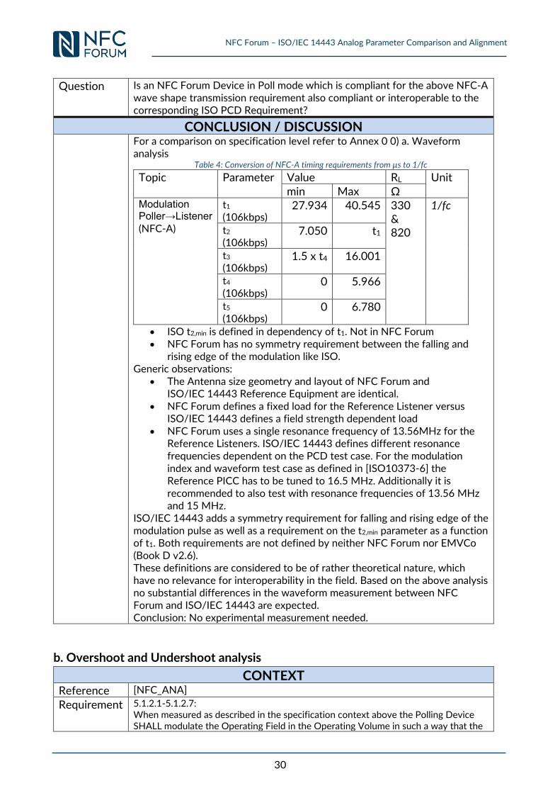
For a comparison on specification level refer to Annex 0 0) a. Waveform analysis
Table 4: Conversion of NFC-A timing requirements from µs to 1/fc
Topic Parameter Value RL Unit min Max Ω
Modulation Poller→Listener (NFC-A)
t1 (106kbps)
27.934 40.545 330 & 820
1/fc
t2 (106kbps)
7.050 t1
t3 (106kbps)
1.5 x t4 16.001
t4 (106kbps)
0 5.966
t5 (106kbps)
0 6.780
ISO t2,min is defined in dependency of t1. Not in NFC Forum NFC Forum has no symmetry requirement between the falling and
rising edge of the modulation like ISO. Generic observations:
The Antenna size geometry and layout of NFC Forum and ISO/IEC 14443 Reference Equipment are identical.
NFC Forum defines a fixed load for the Reference Listener versus ISO/IEC 14443 defines a field strength dependent load
NFC Forum uses a single resonance frequency of 13.56MHz for the Reference Listeners. ISO/IEC 14443 defines different resonance frequencies dependent on the PCD test case. For the modulation index and waveform test case as defined in [ISO10373-6] the Reference PICC has to be tuned to 16.5 MHz. Additionally it is recommended to also test with resonance frequencies of 13.56 MHz and 15 MHz.
ISO/IEC 14443 adds a symmetry requirement for falling and rising edge of the modulation pulse as well as a requirement on the t2,min parameter as a function of t1. Both requirements are not defined by neither NFC Forum nor EMVCo (Book D v2.6). These definitions are considered to be of rather theoretical nature, which have no relevance for interoperability in the field. Based on the above analysis no substantial differences in the waveform measurement between NFC Forum and ISO/IEC 14443 are expected. Conclusion: No experimental measurement needed.
b. Overshoot and Undershoot analysis
CONTEXT
Reference [NFC_ANA]
Requirement 5.1.2.1-5.1.2.7: When measured as described in the specification context above the Polling Device SHALL modulate the Operating Field in the Operating Volume in such a way that the
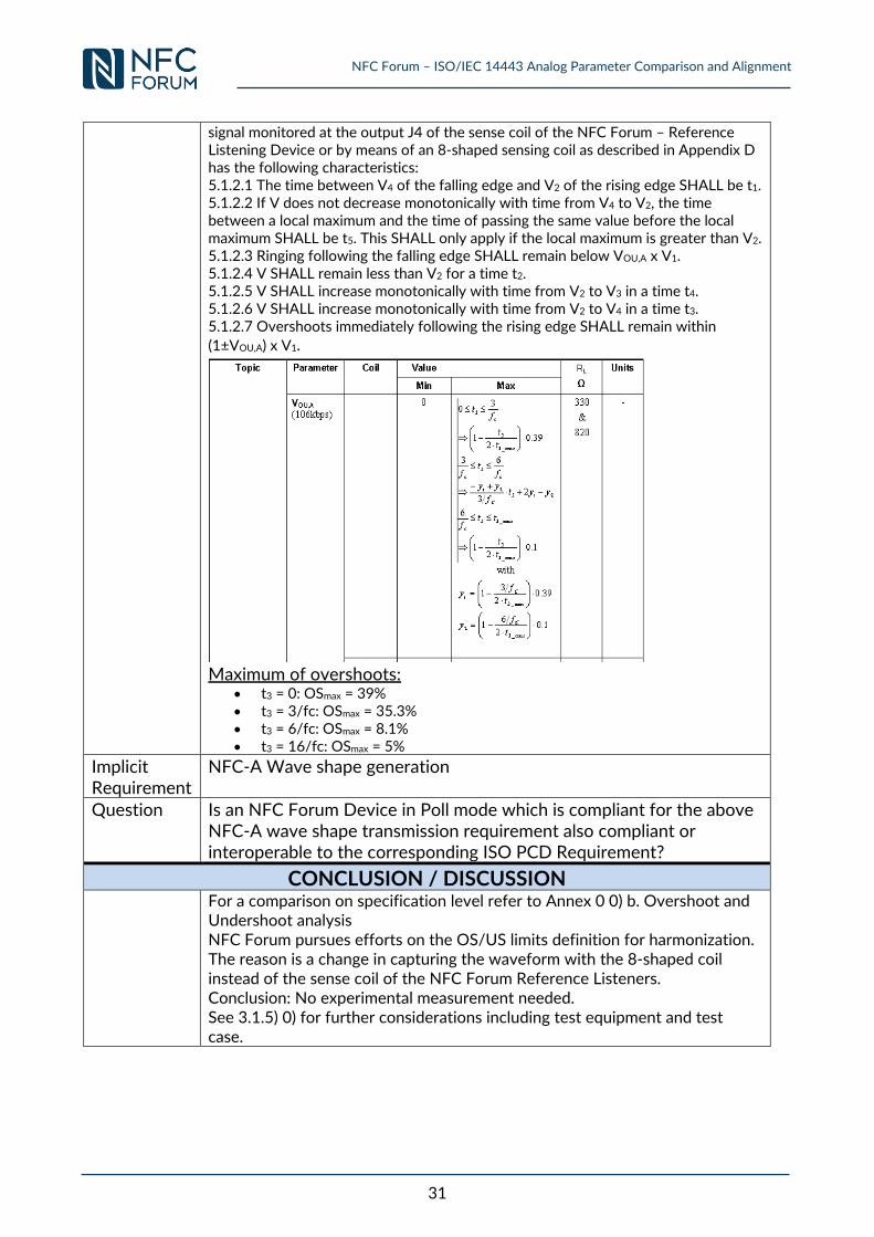
NFC Forum – ISO/IEC 14443 Analog Parameter Comparison and Alignment
31
signal monitored at the output J4 of the sense coil of the NFC Forum – Reference Listening Device or by means of an 8-shaped sensing coil as described in Appendix D has the following characteristics: 5.1.2.1 The time between V4 of the falling edge and V2 of the rising edge SHALL be t1. 5.1.2.2 If V does not decrease monotonically with time from V4 to V2, the time between a local maximum and the time of passing the same value before the local maximum SHALL be t5. This SHALL only apply if the local maximum is greater than V2. 5.1.2.3 Ringing following the falling edge SHALL remain below VOU,A x V1. 5.1.2.4 V SHALL remain less than V2 for a time t2. 5.1.2.5 V SHALL increase monotonically with time from V2 to V3 in a time t4. 5.1.2.6 V SHALL increase monotonically with time from V2 to V4 in a time t3. 5.1.2.7 Overshoots immediately following the rising edge SHALL remain within
(1±VOU,A) x V1.
Maximum of overshoots:
t3 = 0: OSmax = 39% t3 = 3/fc: OSmax = 35.3% t3 = 6/fc: OSmax = 8.1% t3 = 16/fc: OSmax = 5%
Implicit Requirement
NFC-A Wave shape generation
Question Is an NFC Forum Device in Poll mode which is compliant for the above NFC-A wave shape transmission requirement also compliant or interoperable to the corresponding ISO PCD Requirement?
CONCLUSION / DISCUSSION
For a comparison on specification level refer to Annex 0 0) b. Overshoot and Undershoot analysis NFC Forum pursues efforts on the OS/US limits definition for harmonization. The reason is a change in capturing the waveform with the 8-shaped coil instead of the sense coil of the NFC Forum Reference Listeners. Conclusion: No experimental measurement needed. See 3.1.5) 0) for further considerations including test equipment and test case.
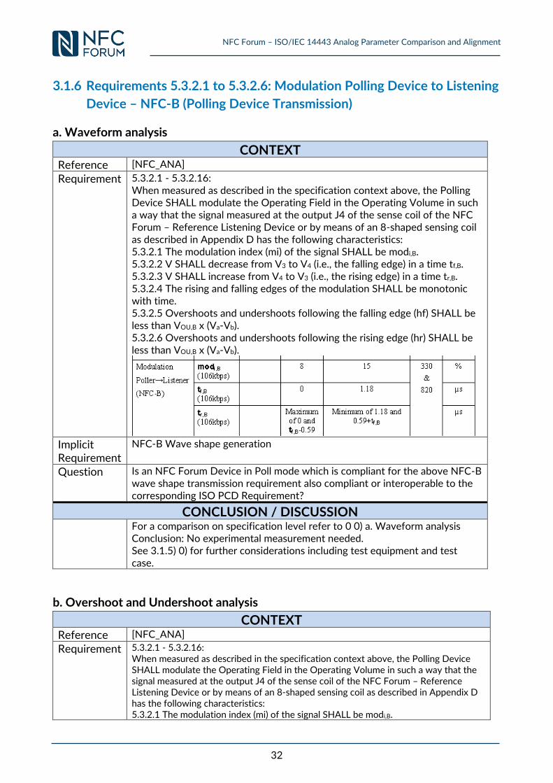
NFC Forum – ISO/IEC 14443 Analog Parameter Comparison and Alignment
32
3.1.6 Requirements 5.3.2.1 to 5.3.2.6: Modulation Polling Device to Listening
Device – NFC-B (Polling Device Transmission)
a. Waveform analysis
CONTEXT
Reference [NFC_ANA]
Requirement 5.3.2.1 - 5.3.2.16: When measured as described in the specification context above, the Polling Device SHALL modulate the Operating Field in the Operating Volume in such a way that the signal measured at the output J4 of the sense coil of the NFC Forum – Reference Listening Device or by means of an 8-shaped sensing coil as described in Appendix D has the following characteristics: 5.3.2.1 The modulation index (mi) of the signal SHALL be modi,B. 5.3.2.2 V SHALL decrease from V3 to V4 (i.e., the falling edge) in a time tf,B. 5.3.2.3 V SHALL increase from V4 to V3 (i.e., the rising edge) in a time tr,B. 5.3.2.4 The rising and falling edges of the modulation SHALL be monotonic with time. 5.3.2.5 Overshoots and undershoots following the falling edge (hf) SHALL be less than VOU,B x (Va-Vb). 5.3.2.6 Overshoots and undershoots following the rising edge (hr) SHALL be less than VOU,B x (Va-Vb).
Implicit Requirement
NFC-B Wave shape generation
Question Is an NFC Forum Device in Poll mode which is compliant for the above NFC-B wave shape transmission requirement also compliant or interoperable to the corresponding ISO PCD Requirement?
CONCLUSION / DISCUSSION
For a comparison on specification level refer to 0 0) a. Waveform analysis Conclusion: No experimental measurement needed. See 3.1.5) 0) for further considerations including test equipment and test case.
b. Overshoot and Undershoot analysis
CONTEXT
Reference [NFC_ANA]
Requirement 5.3.2.1 - 5.3.2.16: When measured as described in the specification context above, the Polling Device SHALL modulate the Operating Field in the Operating Volume in such a way that the signal measured at the output J4 of the sense coil of the NFC Forum – Reference Listening Device or by means of an 8-shaped sensing coil as described in Appendix D has the following characteristics: 5.3.2.1 The modulation index (mi) of the signal SHALL be modi,B.
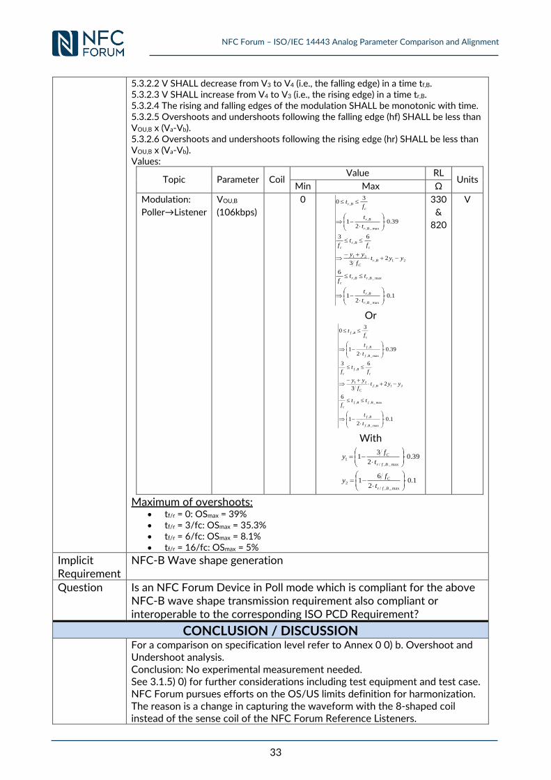
NFC Forum – ISO/IEC 14443 Analog Parameter Comparison and Alignment
33
5.3.2.2 V SHALL decrease from V3 to V4 (i.e., the falling edge) in a time tf,B. 5.3.2.3 V SHALL increase from V4 to V3 (i.e., the rising edge) in a time tr,B. 5.3.2.4 The rising and falling edges of the modulation SHALL be monotonic with time. 5.3.2.5 Overshoots and undershoots following the falling edge (hf) SHALL be less than VOU,B x (Va-Vb). 5.3.2.6 Overshoots and undershoots following the rising edge (hr) SHALL be less than VOU,B x (Va-Vb). Values:
Topic Parameter Coil Value RL
Units Min Max Ω
Modulation:
Poller→Listener
VOU,B
(106kbps)
0
1.02
1
6
23
63
39.02
1
30
max_,
,
max_,,
21,21
,
max_,
,
,
Br
Br
BrBr
c
Br
C
c
Br
c
Br
Br
c
Br
t
t
ttf
yytf
yy
ft
f
t
t
ft
Or
1.02
1
6
23
63
39.02
1
30
max_,
,
max_,,
21,21
,
max_,
,
,
Bf
Bf
BfBf
c
Bf
C
c
Bf
c
Bf
Bf
c
Bf
t
t
ttf
yytf
yy
ft
f
t
t
ft
With
1.02
61
39.02
31
max_,/
2
max_,/
1
Bfr
C
Bfr
C
t
fy
t
fy
330
&
820
V
Maximum of overshoots: tf/r = 0: OSmax = 39% tf/r = 3/fc: OSmax = 35.3% tf/r = 6/fc: OSmax = 8.1% tf/r = 16/fc: OSmax = 5%
Implicit Requirement
NFC-B Wave shape generation
Question Is an NFC Forum Device in Poll mode which is compliant for the above NFC-B wave shape transmission requirement also compliant or interoperable to the corresponding ISO PCD Requirement?
CONCLUSION / DISCUSSION
For a comparison on specification level refer to Annex 0 0) b. Overshoot and Undershoot analysis. Conclusion: No experimental measurement needed. See 3.1.5) 0) for further considerations including test equipment and test case. NFC Forum pursues efforts on the OS/US limits definition for harmonization. The reason is a change in capturing the waveform with the 8-shaped coil instead of the sense coil of the NFC Forum Reference Listeners.
NFC Forum – ISO/IEC 14443 Analog Parameter Comparison and Alignment
34
3.1.7 Requirements 5.5.2.1 to 5.5.2.6: Modulation Polling Device to Listening
Device – NFC-F (Polling Device Transmission)
No experimental measurement needed. Covered by NFC-B analysis.
3.1.8 Requirement 6.5.2.1: Modulation Listening Device to Polling Device
(Polling Device Reception)
a. VPP,min
CONTEXT
Reference [NFC_ANA]
Requirement 6.5.2.1: For NFC-A, NFC-B, and NFC-F, the Polling Device SHALL function properly with the NFC Forum – Reference Listening Device placed in its Operating Volume, provided the NFC Forum – Reference Listening Device has been set up as described in the specification context above.
Implicit Requirement
Minimum load modulation amplitude
Question Is an NFC Forum Device in Poll mode which is compliant for the above minimum load modulation requirement also compliant or interoperable to the corresponding minimum ISO PCD Requirement?
PROCEDURE Step SETUP
NFC Setup 1
Setup the DUT P0 power to exactly ISO Hmin when measured in the whole ISO OV (Hmin must be measured in exactly one point of the OV. All other positions shall have the same or a higher value). The NFC max power shall not be exceeded in the whole NFC OV using NFC Forum – Reference Listeners. Record the measured VOV in the whole NFC OV with each NFC Forum – Reference Listener set to 820 Ω (min power
setup). Note 1: NFC Forum max power has to be measured with NFC Forum – Reference Listeners 1, 3, 6. The ISO min field strength is split into 3 experiments: In the first the setup is done with ISO Reference PICC 1, 2, 3. In the second setup is done only with ISO Reference PICC 1, 2, 3 and 6 and in the third setup is done with ISO Reference PICC 6.
2
Place the NFC Forum – Reference Listener 1 (820 Ω) in NFC OV – 100
of the NFC Forum – Reference Poller 0 and setup the minimum measured VOV as recorded in step 1. Set NFC Forum – Reference Listener 1 to transmit min LMA (VS,PP,min) with 330Ω loading at (100-NFC OV) of NFC Forum – Reference Poller 0. Note: min LMA for L1, L3 and L6 is always setup with NFC Forum – Reference Poller 0
NFC Forum – ISO/IEC 14443 Analog Parameter Comparison and Alignment
35
Topic Parameter Coil Value RL
Units Min Ω
Load
Modulation
(NFC-A, NFC-B,
NFC-F)
VS,pp with
Poller 0 Listener-1 18 330 mVpp Listener-3 26 330 mVpp Listener-6 26 330 mVpp
3 Move the NFC Forum – Reference Listener 1 in whole NFC OV of DUT P0 and measure the LMA at J2 of DUT P0. Record the measured VOV
(Listener with 330Ω load), the minimum LMA and the position.
4 Repeat steps 2) and 3) for NFC Forum – Reference Listener 3 and 6.
4b
Search the minimum LMA of the DUT Poller amongst all NFC Forum – Reference Listener. Note: It is assumed that the DUT Poller sensitivity is the value of the global min LMA independent on the Reference Listener antenna size and field strength seen by the Reference Listener.
5
Repeat steps 1) – 4) setting up the DUT Poller to the VOV,max in step 1.
Note: Care should be taken to be within Hmin and Hmax of ISO for a) classes 1-3, b) class 1-3 and class 6 and c) Class 6 only.
6 Repeat steps 1) - 5) for DUT P3 and DUT P6.
8 ISO SETUP:
Tune the resonance frequency of each of the ISO Reference PICC 1, 2, 3 and 6 to 13,56 MHz.
Step VERIFICATION
1
For each position of the ISO OV perform the steps below: Place the ISO Reference PICC 1 in each position of the complete ISO OV of the DUT P0 and adjust the load so that the voltage measured at CON3 matches the Vload value defined in Table 21.
2 Increase the amplitude of the load modulation of the ISO Reference PICC 1 until the min value for the position (see setup step 4b) measured by the DUT P0 J2 output is reached.
3 Place the ISO Reference PICC 1 in the DUT position of the respective Test PCD assembly and adjust the field strength until the value defined in Table 21 is measured at CON3.
4 Read the field strength measured at the calibration coil.
5 Measure the load modulation amplitude.
6 Repeat the VERIFICATION steps 1-5 for ISO Reference PICC 2, 3 and 6.
7 Repeat VERIFICATION steps 1-6 for DUT P3 and DUT P6.
8 Repeat VERIFICATION procedure step 1-7 for each of the Reference PICCs 1, 2, 3 and 6 tuned to 15 MHz resonance frequency.
EXPECTED OUTCOME
Step COMPLIANCY
1 Compare the measured LMA and field strengths of VERIFICATION step 4 and 5 to the ISO PCD limits of Table 24.
Step INTEROPERABILITY
1 Compare the measured LMA and field strengths of VERIFICATION step 4 and 5 to the ISO PICC limits of [ISO14443-2].
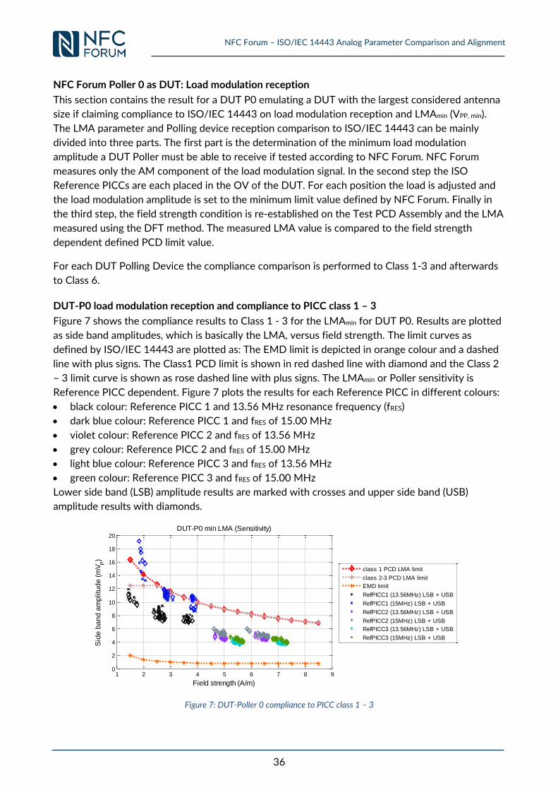
NFC Forum – ISO/IEC 14443 Analog Parameter Comparison and Alignment
36
NFC Forum Poller 0 as DUT: Load modulation reception
This section contains the result for a DUT P0 emulating a DUT with the largest considered antenna
size if claiming compliance to ISO/IEC 14443 on load modulation reception and LMAmin (VPP, min).
The LMA parameter and Polling device reception comparison to ISO/IEC 14443 can be mainly
divided into three parts. The first part is the determination of the minimum load modulation
amplitude a DUT Poller must be able to receive if tested according to NFC Forum. NFC Forum
measures only the AM component of the load modulation signal. In the second step the ISO
Reference PICCs are each placed in the OV of the DUT. For each position the load is adjusted and
the load modulation amplitude is set to the minimum limit value defined by NFC Forum. Finally in
the third step, the field strength condition is re-established on the Test PCD Assembly and the LMA
measured using the DFT method. The measured LMA value is compared to the field strength
dependent defined PCD limit value.
For each DUT Polling Device the compliance comparison is performed to Class 1-3 and afterwards
to Class 6.
DUT-P0 load modulation reception and compliance to PICC class 1 – 3
Figure 7 shows the compliance results to Class 1 - 3 for the LMAmin for DUT P0. Results are plotted
as side band amplitudes, which is basically the LMA, versus field strength. The limit curves as
defined by ISO/IEC 14443 are plotted as: The EMD limit is depicted in orange colour and a dashed
line with plus signs. The Class1 PCD limit is shown in red dashed line with diamond and the Class 2
– 3 limit curve is shown as rose dashed line with plus signs. The LMAmin or Poller sensitivity is
Reference PICC dependent. Figure 7 plots the results for each Reference PICC in different colours:
black colour: Reference PICC 1 and 13.56 MHz resonance frequency (fRES)
dark blue colour: Reference PICC 1 and fRES of 15.00 MHz
violet colour: Reference PICC 2 and fRES of 13.56 MHz
grey colour: Reference PICC 2 and fRES of 15.00 MHz
light blue colour: Reference PICC 3 and fRES of 13.56 MHz
green colour: Reference PICC 3 and fRES of 15.00 MHz
Lower side band (LSB) amplitude results are marked with crosses and upper side band (USB)
amplitude results with diamonds.
Figure 7: DUT-Poller 0 compliance to PICC class 1 – 3
1 2 3 4 5 6 7 8 90
2
4
6
8
10
12
14
16
18
20
Field strength (A/m)
Sid
e b
an
d a
mp
litu
de
(m
VP)
DUT-P0 min LMA (Sensitivity)
class 1 PCD LMA limit
class 2-3 PCD LMA limit
EMD limit
RefPICC1 (13.56MHz) LSB + USB
RefPICC1 (15MHz) LSB + USB
RefPICC2 (13.56MHz) LSB + USB
RefPICC2 (15MHz) LSB + USB
RefPICC3 (13.56MHz) LSB + USB
RefPICC3 (15MHz) LSB + USB
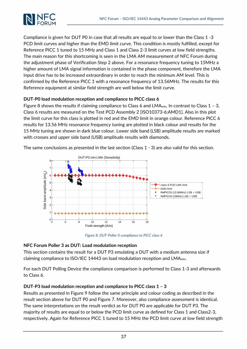
NFC Forum – ISO/IEC 14443 Analog Parameter Comparison and Alignment
37
Compliance is given for DUT P0 in case that all results are equal to or lower than the Class 1 -3
PCD limit curves and higher than the EMD limit curve. This condition is mostly fulfilled, except for
Reference PICC 1 tuned to 15 MHz and Class 1 and Class 2-3 limit curves at low field strengths.
The main reason for this shortcoming is seen in the LMA AM measurement of NFC Forum during
the adjustment phase of Verification Step 2 above. For a resonance frequency tuning to 15MHz a
higher amount of LMA signal information is contained in the phase component, therefore the LMA
input drive has to be increased extraordinary in order to reach the minimum AM level. This is
confirmed by the Reference PICC 1 with a resonance frequency of 13.56MHz. The results for this
Reference equipment at similar field strength are well below the limit curve.
DUT-P0 load modulation reception and compliance to PICC class 6
Figure 8 shows the results if claiming compliance to Class 6 and LMAmin. In contrast to Class 1 – 3,
Class 6 results are measured on the Test PCD Assembly 2 [ISO10373-6:AMD1]. Also in this plot
the limit curve for this class is plotted in red and the EMD limit in orange colour. Reference PICC 6
results for 13.56 MHz resonance frequency tuning are plotted in black colour and results for the
15 MHz tuning are shown in dark blue colour. Lower side band (LSB) amplitude results are marked
with crosses and upper side band (USB) amplitude results with diamonds.
The same conclusions as presented in the last section (Class 1 - 3) are also valid for this section.
Figure 8: DUT-Poller 0 compliance to PICC class 6
NFC Forum Poller 3 as DUT: Load modulation reception
This section contains the result for a DUT P3 emulating a DUT with a medium antenna size if
claiming compliance to ISO/IEC 14443 on load modulation reception and LMAmin.
For each DUT Polling Device the compliance comparison is performed to Class 1-3 and afterwards
to Class 6.
DUT-P3 load modulation reception and compliance to PICC class 1 – 3
Results as presented in Figure 9 follow the same principle and colour coding as described in the
result section above for DUT P0 and Figure 7. Moreover, also compliance assessment is identical.
The same interpretations on the result verdict as for DUT P0 are applicable for DUT P3. The
majority of results are equal to or below the PCD limit curve as defined for Class 1 and Class2-3,
respectively. Again for Reference PICC 1 tuned to 15 MHz the PCD limit curve at low field strength
4 6 8 10 12 14 16 180
1
2
3
4
5
6
7
8
Field strength (A/m)
Sid
e b
an
d a
mp
litu
de
(m
VP)
DUT-P0 min LMA (Sensitivity)
class 6 PCD LMA limit
EMD limit
RefPICC6 (13.56MHz) LSB + USB
RefPICC6 (15MHz) LSB + USB
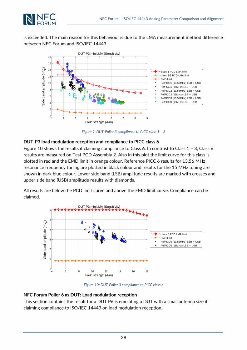
NFC Forum – ISO/IEC 14443 Analog Parameter Comparison and Alignment
38
is exceeded. The main reason for this behaviour is due to the LMA measurement method difference
between NFC Forum and ISO/IEC 14443.
Figure 9: DUT-Poller 3 compliance to PICC class 1 – 3
DUT-P3 load modulation reception and compliance to PICC class 6
Figure 10 shows the results if claiming compliance to Class 6. In contrast to Class 1 – 3, Class 6
results are measured on Test PCD Assembly 2. Also in this plot the limit curve for this class is
plotted in red and the EMD limit in orange colour. Reference PICC 6 results for 13.56 MHz
resonance frequency tuning are plotted in black colour and results for the 15 MHz tuning are
shown in dark blue colour. Lower side band (LSB) amplitude results are marked with crosses and
upper side band (USB) amplitude results with diamonds.
All results are below the PCD limit curve and above the EMD limit curve. Compliance can be
claimed.
Figure 10: DUT-Poller 3 compliance to PICC class 6
NFC Forum Poller 6 as DUT: Load modulation reception
This section contains the result for a DUT P6 is emulating a DUT with a small antenna size if
claiming compliance to ISO/IEC 14443 on load modulation reception.
1 2 3 4 5 6 7 8 90
2
4
6
8
10
12
14
16
18
Field strength (A/m)
Sid
e b
an
d a
mp
litu
de
(m
VP)
DUT-P3 min LMA (Sensitivity)
class 1 PCD LMA limit
class 2-3 PCD LMA limit
EMD limit
RefPICC1 (13.56MHz) LSB + USB
RefPICC1 (15MHz) LSB + USB
RefPICC2 (13.56MHz) LSB + USB
RefPICC2 (15MHz) LSB + USB
RefPICC3 (13.56MHz) LSB + USB
RefPICC3 (15MHz) LSB + USB
4 6 8 10 12 14 16 180
1
2
3
4
5
6
Field strength (A/m)
Sid
e b
an
d a
mp
litu
de
(m
VP)
DUT-P3 min LMA (Sensitivity)
class 6 PCD LMA limit
EMD limit
RefPICC6 (13.56MHz) LSB + USB
RefPICC6 (15MHz) LSB + USB
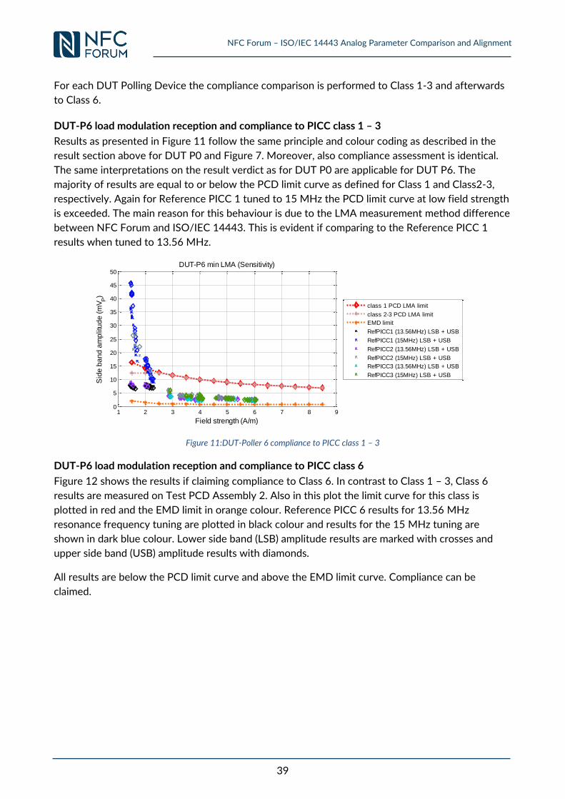
NFC Forum – ISO/IEC 14443 Analog Parameter Comparison and Alignment
39
For each DUT Polling Device the compliance comparison is performed to Class 1-3 and afterwards
to Class 6.
DUT-P6 load modulation reception and compliance to PICC class 1 – 3
Results as presented in Figure 11 follow the same principle and colour coding as described in the
result section above for DUT P0 and Figure 7. Moreover, also compliance assessment is identical.
The same interpretations on the result verdict as for DUT P0 are applicable for DUT P6. The
majority of results are equal to or below the PCD limit curve as defined for Class 1 and Class2-3,
respectively. Again for Reference PICC 1 tuned to 15 MHz the PCD limit curve at low field strength
is exceeded. The main reason for this behaviour is due to the LMA measurement method difference
between NFC Forum and ISO/IEC 14443. This is evident if comparing to the Reference PICC 1
results when tuned to 13.56 MHz.
Figure 11:DUT-Poller 6 compliance to PICC class 1 – 3
DUT-P6 load modulation reception and compliance to PICC class 6
Figure 12 shows the results if claiming compliance to Class 6. In contrast to Class 1 – 3, Class 6
results are measured on Test PCD Assembly 2. Also in this plot the limit curve for this class is
plotted in red and the EMD limit in orange colour. Reference PICC 6 results for 13.56 MHz
resonance frequency tuning are plotted in black colour and results for the 15 MHz tuning are
shown in dark blue colour. Lower side band (LSB) amplitude results are marked with crosses and
upper side band (USB) amplitude results with diamonds.
All results are below the PCD limit curve and above the EMD limit curve. Compliance can be
claimed.
1 2 3 4 5 6 7 8 90
5
10
15
20
25
30
35
40
45
50
Field strength (A/m)
Sid
e b
an
d a
mp
litu
de
(m
VP)
DUT-P6 min LMA (Sensitivity)
class 1 PCD LMA limit
class 2-3 PCD LMA limit
EMD limit
RefPICC1 (13.56MHz) LSB + USB
RefPICC1 (15MHz) LSB + USB
RefPICC2 (13.56MHz) LSB + USB
RefPICC2 (15MHz) LSB + USB
RefPICC3 (13.56MHz) LSB + USB
RefPICC3 (15MHz) LSB + USB
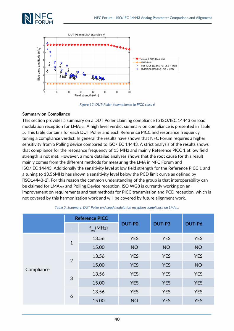
NFC Forum – ISO/IEC 14443 Analog Parameter Comparison and Alignment
40
Figure 12: DUT-Poller 6 compliance to PICC class 6
Summary on Compliance
This section provides a summary on a DUT Poller claiming compliance to ISO/IEC 14443 on load
modulation reception for LMAmin. A high level verdict summary on compliance is presented in Table
5. This table contains for each DUT Poller and each Reference PICC and resonance frequency
tuning a compliance verdict. In general the results have shown that NFC Forum requires a higher
sensitivity from a Polling device compared to ISO/IEC 14443. A strict analysis of the results shows
that compliance for the resonance frequency of 15 MHz and mainly Reference PICC 1 at low field
strength is not met. However, a more detailed analyses shows that the root cause for this result
mainly comes from the different methods for measuring the LMA in NFC Forum and
ISO/IEC 14443. Additionally the sensitivity level at low field strength for the Reference PICC 1 and
a tuning to 13.56MHz has shown a sensitivity level below the PCD limit curve as defined by
[ISO14443-2]. For this reason the common understanding of the group is that interoperability can
be claimed for LMAmin and Polling Device reception. ISO WG8 is currently working on an
improvement on requirements and test methods for PICC transmission and PCD reception, which is
not covered by this harmonization work and will be covered by future alignment work.
Table 5: Summary: DUT Poller and Load modulation reception compliance on LMAmin
Reference PICC
DUT-P0 DUT-P3 DUT-P6 - f
res(MHz)
Compliance
1 13.56 YES YES YES
15.00 NO NO NO
2 13.56 YES YES YES
15.00 YES YES NO
3 13.56 YES YES YES
15.00 YES YES YES
6 13.56 YES YES YES
15.00 NO YES YES
4 6 8 10 12 14 16 180
1
2
3
4
5
6
7
Field strength (A/m)
Sid
e b
an
d a
mp
litu
de
(m
VP)
DUT-P6 min LMA (Sensitivity)
class 6 PCD LMA limit
EMD limit
RefPICC6 (13.56MHz) LSB + USB
RefPICC6 (15MHz) LSB + USB
NFC Forum – ISO/IEC 14443 Analog Parameter Comparison and Alignment
41
b. VPP,max
CONTEXT
Reference [NFC_ANA]
Requirement 6.5.2.1: For NFC-A, NFC-B, and NFC-F, the Polling Device SHALL function properly with the NFC Forum – Reference Listening Device placed in its Operating Volume, provided the NFC Forum – Reference Listening Device has been set up as described in the specification context above.
Implicit Requirement
Maximum load modulation amplitude
Question Is an NFC Forum Device in Poll mode which is compliant for the above maximum load modulation requirement also compliant or interoperable to the corresponding maximum ISO PCD Requirement?
PROCEDURE Step SETUP
NFC Setup 1
Setup the DUT P0 power to exactly ISO Hmin when measured in the whole ISO OV (Hmin must be measured in exactly one point of the OV. All other positions shall have the same or higher value). The NFC max power shall not be exceeded in the whole NFC OV using NFC Forum – Reference Listeners. Record the measured VOV in the whole NFC OV with each NFC Forum – Reference Listener set to 820 Ω (min power setup). Note 1: NFC Forum max power has to be measured with NFC Forum – Reference Listeners 1, 3, 6. The ISO min field strength is split into 3 experiments: In the first the setup is done with ISO Reference PICC 1, 2, 3. In the second setup is done only with ISO Reference PICC 1, 2, 3 and 6 and in the third setup is done with ISO Reference PICC 6.
2
Place the NFC Forum – Reference Listener 1 (820 Ω) in NFC OV – 100 of
the NFC Forum – Reference Poller and setup to the maximum VOV as recorded in step 1. Setup the NFC Forum – Reference Listener 1 to transmit max LMA with 330Ω loading at (100-NFC OV) on the respective NFC Forum – Reference Poller. Note: for max LMA setup the following Reference Equipment configurations are used: P0-L1, P3-L3, P6-L6
Topic Parameter Coil Value RL
Units Max Ω
Load Modulation
(NFC-A, NFC-B,
NFC-F)
VS,pp Poller0 with Listener-1
114
330 mVpp Poller3 with Listener-3
54
Poller6 with Listener-6
90
3
Move NFC Forum – Listener 1 in whole NFC OV of DUT P0 and measure the LMA at J2 of DUT P0. Record the measured VOV (Listener with 330Ω
load), the maximum LMA and the position.
4 Repeat steps 2) and 3) for NFC Forum – Reference Listener 3 and 6. Note: In step 2) the according NFC Forum – Reference Poller has to be used.
5 Search the maximum LMA of the DUT Poller amongst all NFC Forum – Reference Listener.
NFC Forum – ISO/IEC 14443 Analog Parameter Comparison and Alignment
42
Note: It is assumed that the DUT Poller maximum is the value of the global max LMA independent on the Reference Listener antenna size and field strength seen by the Reference Listener.
6
Repeat steps 1) – 4) setting up the DUT Poller to the VOV,max in step 1.
Note: Care should be taken to be within Hmin and Hmax of ISO for a) classes 1-3, b) class 1-3 and class 6 and c) Class 6 only.
7 Repeat steps 1) - 6) for DUT P3 and DUT P6.
8 ISO SETUP
Tune the resonance frequency of each of the ISO Reference PICC 1, 2, 3 and 6 to 13,56 MHz.
Step VERIFICATION
1
For each position of the ISO OV perform the steps below: Place the ISO Reference PICC 1 in each position of the compete ISO OV of the DUT P0 and adjust the load measured at CON3 to the value defined in Table 21.
2 Increase the amplitude of the load modulation of the ISO Reference PICC 1 until the max value measured by the DUT P0 J2 output for this position (see setup step 5) is reached.
3 Place the ISO Reference PICC 1 in the DUT position of the respective Test PCD assembly and adjust the field strength until the value defined in Table 21 is measured at CON3.
4 Read the field strength measured at the calibration coil.
5 Measure the load modulation amplitude.
6 Repeat the VERIFICATION steps for ISO Reference PICC 2, 3 and 6.
7 Repeat VERIFICATION steps 1-6 for DUT P3 and DUT P6.
8 Repeat VERIFICATION procedure 1-7 for each of the Reference PICCs 1, 2, 3 and 6 tuned to 15 MHz resonance frequency.
EXPECTED OUTCOME
Step COMPLIANCY 1 n.a.
Step INTEROPERABILITY 1 n.a.
RESULT
n.a.
Verdict
Inte
rop
era
bil
ity
Co
mp
lia
ncy
CONCLUSION / DISCUSSION
[ISO14443-2] does not define maximum LMA limit. Thus this procedure is seen as an input for further discussions.
NFC Forum – ISO/IEC 14443 Analog Parameter Comparison and Alignment
43
3.2 Listening Device Requirements
This section contains the procedure and comparison results for the following parameter limits:
Power Transfer from Polling Device to Listening Device (Listening Device Reception)
o Minimum field strength
o Maximum field strength
Influence of the Listening Device on the Operating Field
Listening Device Reset (Listening Device Reception)
Modulation Polling Device to Listening Device – NFC-A (Listening Device Reception)
o Waveform Analysis
o Overshoot and Undershoot analysis
Modulation Polling Device to Listening Device – NFC-B (Listening Device Reception)
o Waveform Analysis
o Overshoot and Undershoot analysis
Modulation Listening Device to Polling Device (Listening Device Transmission)
o Minimum load modulation amplitude
o Maximum load modulation amplitude
3.2.1 Requirements 4.2.2.1 & 4.2.2.2 & 4.2.2.3: Power Transfer from Polling
Device to Listening Device (Listening Device Reception)
a. Minimum field strength
CONTEXT
Reference [NFC_ANA]
Requirement 4.2.2.1-4.2.2.3: 4.2.2.1 A Listening Device SHALL function properly within the Operating Volume of the NFC Forum – Reference Polling Device when the operating conditions have been established as described in the specification context above for NFC-A. See Section 3.4 for definition of “function properly”. 4.2.2.2 A Listening Device SHALL function properly within the Operating Volume of the NFC Forum – Reference Polling Device when the operating conditions have been established as described in the specification context above for NFC-B. 4.2.2.3 A Listening Device SHALL function properly within the Operating Volume of the NFC Forum – Reference Polling Device when the operating conditions have been established as described in the specification context above for NFC-F.
Implicit Requirement
Minimum power reception
Question Is an NFC Forum Device in Listen mode which is compliant for the above minimum power reception requirement also compliant or interoperable to the corresponding minimum ISO PICC Requirement?
PROCEDURE Step SETUP
1 NFC Setup:
Setup the 3 NFC Forum – Reference Pollers to generate listener minimum field strength with NFC Forum – Reference Listener 1 at (100 – NFC OV).
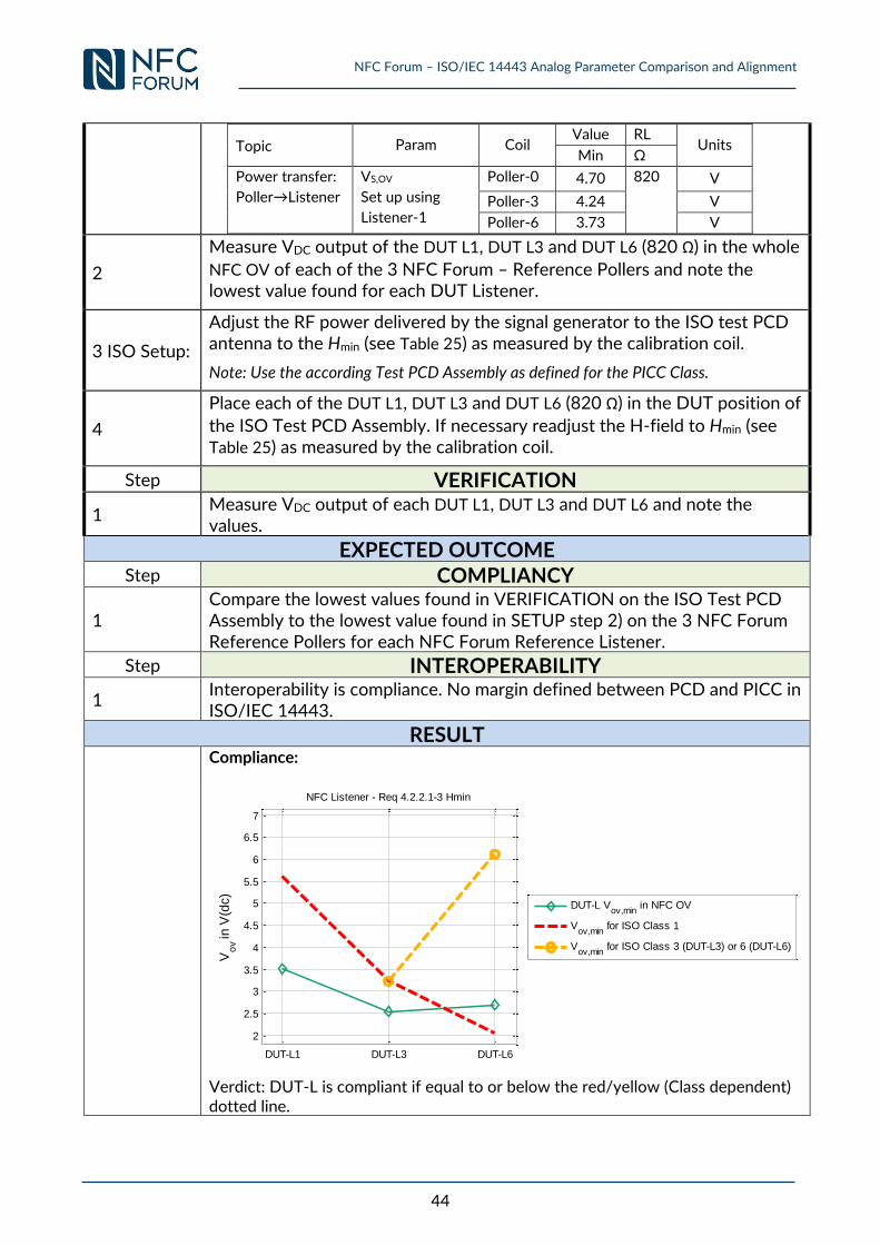
NFC Forum – ISO/IEC 14443 Analog Parameter Comparison and Alignment
44
Topic Param Coil Value RL
Units Min Ω
Power transfer:
Poller→Listener
VS,OV
Set up using
Listener-1
Poller-0 4.70 820 V
Poller-3 4.24 V
Poller-6 3.73 V
2
Measure VDC output of the DUT L1, DUT L3 and DUT L6 (820 Ω) in the whole
NFC OV of each of the 3 NFC Forum – Reference Pollers and note the lowest value found for each DUT Listener.
3 ISO Setup:
Adjust the RF power delivered by the signal generator to the ISO test PCD antenna to the Hmin (see Table 25) as measured by the calibration coil.
Note: Use the according Test PCD Assembly as defined for the PICC Class.
4
Place each of the DUT L1, DUT L3 and DUT L6 (820 Ω) in the DUT position of
the ISO Test PCD Assembly. If necessary readjust the H-field to Hmin (see Table 25) as measured by the calibration coil.
Step VERIFICATION
1 Measure VDC output of each DUT L1, DUT L3 and DUT L6 and note the values.
EXPECTED OUTCOME
Step COMPLIANCY
1 Compare the lowest values found in VERIFICATION on the ISO Test PCD Assembly to the lowest value found in SETUP step 2) on the 3 NFC Forum Reference Pollers for each NFC Forum Reference Listener.
Step INTEROPERABILITY
1 Interoperability is compliance. No margin defined between PCD and PICC in ISO/IEC 14443.
RESULT
Compliance:
Verdict: DUT-L is compliant if equal to or below the red/yellow (Class dependent) dotted line.
DUT-L1 DUT-L3 DUT-L6
2
2.5
3
3.5
4
4.5
5
5.5
6
6.5
7
Vo
v in
V(d
c)
NFC Listener - Req 4.2.2.1-3 Hmin
DUT-L Vov,min
in NFC OV
Vov,min
for ISO Class 1
Vov,min
for ISO Class 3 (DUT-L3) or 6 (DUT-L6)
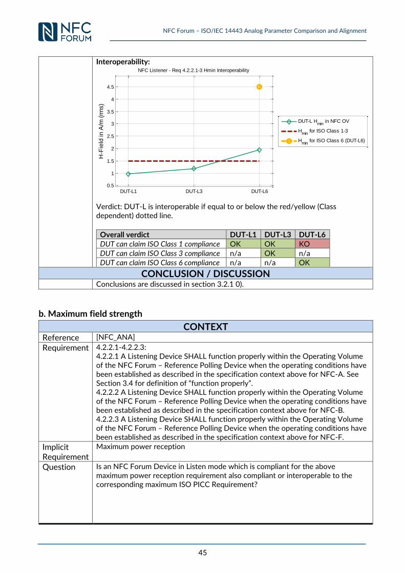
NFC Forum – ISO/IEC 14443 Analog Parameter Comparison and Alignment
45
Interoperability:
Verdict: DUT-L is interoperable if equal to or below the red/yellow (Class dependent) dotted line.
Overall verdict DUT-L1 DUT-L3 DUT-L6 DUT can claim ISO Class 1 compliance OK OK KO
DUT can claim ISO Class 3 compliance n/a OK n/a DUT can claim ISO Class 6 compliance n/a n/a OK
CONCLUSION / DISCUSSION
Conclusions are discussed in section 3.2.1 0).
b. Maximum field strength
CONTEXT
Reference [NFC_ANA]
Requirement 4.2.2.1-4.2.2.3: 4.2.2.1 A Listening Device SHALL function properly within the Operating Volume of the NFC Forum – Reference Polling Device when the operating conditions have been established as described in the specification context above for NFC-A. See Section 3.4 for definition of “function properly”. 4.2.2.2 A Listening Device SHALL function properly within the Operating Volume of the NFC Forum – Reference Polling Device when the operating conditions have been established as described in the specification context above for NFC-B. 4.2.2.3 A Listening Device SHALL function properly within the Operating Volume of the NFC Forum – Reference Polling Device when the operating conditions have been established as described in the specification context above for NFC-F.
Implicit Requirement
Maximum power reception
Question Is an NFC Forum Device in Listen mode which is compliant for the above maximum power reception requirement also compliant or interoperable to the corresponding maximum ISO PICC Requirement?
DUT-L1 DUT-L3 DUT-L60.5
1
1.5
2
2.5
3
3.5
4
4.5
H-F
ield
in
A/m
(rm
s)
NFC Listener - Req 4.2.2.1-3 Hmin Interoperability
DUT-L Hmin
in NFC OV
Hmin
for ISO Class 1-3
Hmin
for ISO Class 6 (DUT-L6)
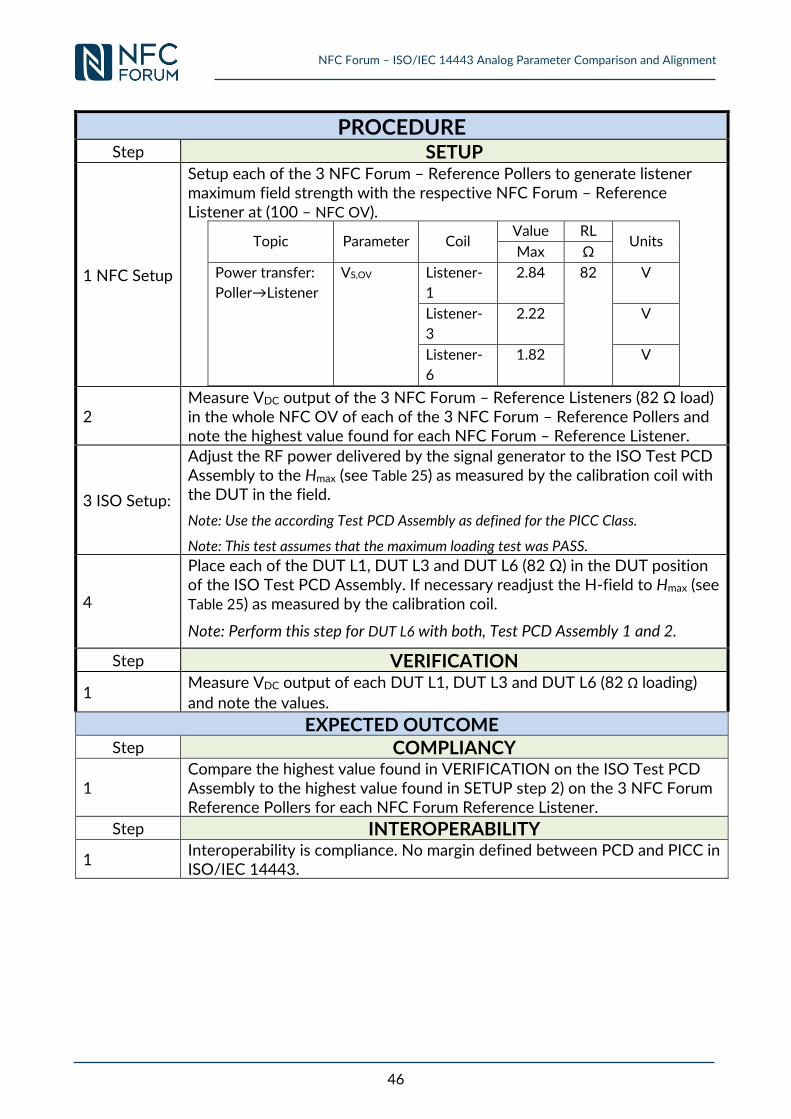
NFC Forum – ISO/IEC 14443 Analog Parameter Comparison and Alignment
46
PROCEDURE Step SETUP
1 NFC Setup
Setup each of the 3 NFC Forum – Reference Pollers to generate listener maximum field strength with the respective NFC Forum – Reference Listener at (100 – NFC OV).
Topic Parameter Coil Value RL
Units Max Ω
Power transfer:
Poller→Listener
VS,OV Listener-
1
2.84 82 V
Listener-
3
2.22 V
Listener-
6
1.82 V
2 Measure VDC output of the 3 NFC Forum – Reference Listeners (82 Ω load) in the whole NFC OV of each of the 3 NFC Forum – Reference Pollers and note the highest value found for each NFC Forum – Reference Listener.
3 ISO Setup:
Adjust the RF power delivered by the signal generator to the ISO Test PCD Assembly to the Hmax (see Table 25) as measured by the calibration coil with the DUT in the field.
Note: Use the according Test PCD Assembly as defined for the PICC Class.
Note: This test assumes that the maximum loading test was PASS.
4
Place each of the DUT L1, DUT L3 and DUT L6 (82 Ω) in the DUT position of the ISO Test PCD Assembly. If necessary readjust the H-field to Hmax (see Table 25) as measured by the calibration coil.
Note: Perform this step for DUT L6 with both, Test PCD Assembly 1 and 2.
Step VERIFICATION
1 Measure VDC output of each DUT L1, DUT L3 and DUT L6 (82 Ω loading)
and note the values.
EXPECTED OUTCOME
Step COMPLIANCY
1 Compare the highest value found in VERIFICATION on the ISO Test PCD Assembly to the highest value found in SETUP step 2) on the 3 NFC Forum Reference Pollers for each NFC Forum Reference Listener.
Step INTEROPERABILITY
1 Interoperability is compliance. No margin defined between PCD and PICC in ISO/IEC 14443.
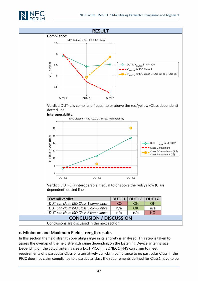
NFC Forum – ISO/IEC 14443 Analog Parameter Comparison and Alignment
47
RESULT
Compliance:
Verdict: DUT-L is compliant if equal to or above the red/yellow (Class dependent) dotted line. Interoperability:
Verdict: DUT-L is interoperable if equal to or above the red/yellow (Class dependent) dotted line.
Overall verdict DUT-L1 DUT-L3 DUT-L6 DUT can claim ISO Class 1 compliance KO OK OK DUT can claim ISO Class 3 compliance n/a OK n/a
DUT can claim ISO Class 6 compliance n/a n/a KO
CONCLUSION / DISCUSSION
Conclusions are discussed in the next section
c. Minimum and Maximum Field strength results In this section the field strength operating range in its entirety is analysed. This step is taken to
assess the overlap of the field strength range depending on the Listening Device antenna size.
Depending on the actual antenna size a DUT PICC in ISO/IEC14443 can claim to meet
requirements of a particular Class or alternatively can claim compliance to no particular Class. If the
PICC does not claim compliance to a particular class the requirements defined for Class1 have to be
DUT-L1 DUT-L3 DUT-L6
1.5
2
2.5
3
3.5
Vo
v in
V(d
c)
NFC Listener - Req 4.2.2.1-3 Hmax
DUT-L Vov,max
in NFC OV
Vov,max
for ISO Class 1
Vov,max
for ISO Class 3 (DUT-L3) or 6 (DUT-L6)
DUT-L1 DUT-L3 DUT-L6
6
8
10
12
14
16
18
H-F
ield
in
A/m
(rm
s)
NFC Listener - Req 4.2.2.1-3 Hmax Interoperability
DUT-L Hmax
in NFC OV
Class 1 maximum
Class 2-3 maximum (8.5)
Class 6 maximum (18)
NFC Forum – ISO/IEC 14443 Analog Parameter Comparison and Alignment
48
met. Regarding the Hmin limit parameter there is no difference between Class 1 to Class 3. In order
to ensure interoperability it is sufficient to be in line with Class 1 or Class 2 or Class 3 requirements
since a compliant PCD mandatorily has to support these 3 classes. Whenever a DUT Listener claim
compliance to no particular Class ("No Class") either Class 1, Class 2 or Class 3 defined
requirements will be met. Compliance/ interoperability for the DUT Listener against the ISO/IEC
14443 selected Class can be claimed if:
1) the minimum value of VOV measured with the DUT Listener in the NFC OV on the
Reference Pollers P0, P3 and P6 setup to minimum power condition is equal to or
below the value of VOV measured on the Test PCD Assembly (1 or 2) adjusted to the
minimum field strength condition for the selected Class as defined in Table 25 using
the according ISO Reference PICC.
2) the maximum value of VOV measured with the DUT Listener in the NFC OV on the
Reference Pollers P0, P3 and P6 setup to maximum power condition is equal to or
above the value of VOV measured on the Test PCD Assembly (1 or 2) adjusted to the
maximum field strength condition for the selected Class as defined in Table 25 using
the according ISO Reference PICC.
NFC Forum Listener 1 emulates a DUT (rectangular:71,6 x 41,5mm)
The NFC Forum Listener 1 (DUT L1) is emulating a DUT with the largest antenna size. In the
subsection below comparison results for Class 1 is provided. Compliance against other Classes is
not applicable.
NFC Listening Device Power Reception - Class 1
[ISO14443-2] does not apply the margin principle for PCD and PICC limit values for the field
strength parameter. For this reason compliance and interoperability verdicts are identical.
Compliance/interoperability for the DUT L1 against Class 1 can be claimed for the minimum value
of VOV, but not for the maximum VOV value. As the difference for the maximum is insignificant, the
group of experts concluded not to take any further action.
NFC Forum Listener 3 emulates a DUT (rectangular:46 x 32mm)
The NFC Forum Listener 3 (DUT L3) is emulating a DUT with a medium antenna size. This antenna
size range is commonly used in mobile devices. In the first subsection below comparison results for
Class 1 and in the second subsection comparison results for Class 3 are provided.
NFC Listening Device Power Reception - Class 1
[ISO14443-2] does not apply the margin principle for PCD and PICC limit values for the field
strength parameter. For this reason compliance and interoperability verdicts are identical.
Compliance/interoperability for the DUT L3 against Class 1 is given for the minimum value of VOV,
and for the maximum value.
NFC Listening Device Power Reception - Class 3
[ISO14443-2] does not apply the margin principle for PCD and PICC limit values for the field
strength parameter. For this reason compliance and interoperability verdicts are identical.
NFC Forum – ISO/IEC 14443 Analog Parameter Comparison and Alignment
49
Compliance/ interoperability for the DUT L3 against Class 3 is given for the minimum value of VOV,
and for the maximum value.
NFC Forum Listener 6 emulates a DUT (rectangular:24,7 x 19,7mm)
The NFC Forum Listener 6 (DUT L6) is emulating a DUT with a small antenna size. This antenna size
range is commonly used in mobile devices. In the first subsection below comparison results for
Class 1 and in the second subsection comparison results for Class 6 are provided. Compliance for
Class 3 is not applicable.
NFC Listening Device Power Reception - Class 1
[ISO14443-2] does not apply the margin principle for PCD and PICC limit values for the field
strength parameter. For this reason compliance and interoperability verdicts are identical.
Compliance/ interoperability for the DUT L6 against Class 1 is not given for the minimum value of
VOV, but for the maximum value. Taking into account the PT specific requirement for PCDs on Hmin
as defined in [CEN/TS 16794-1] interoperability can be claimed for a NFC Device using an antenna
size of Class 6. [CEN TS16794-1] requires an Hmin of at least 2 A/m(rms) if measured with a
Reference PICC 3. An NFC Device of Class 6 is tested at a minimum field strength of 1.9 A/m(rms).
NFC Listening Device Power Reception – Class 6
[ISO14443-2] does not apply the margin principle for PCD and PICC limit values for the field
strength parameter. For this reason compliance and interoperability verdicts are identical.
Compliance/ interoperability for the DUT L6 against Class 6 is given for the minimum value of VOV,
but not for the maximum value.
Summary and Recommendations
The NFC Forum Reference Listening Devices have been chosen to emulate the relevant antenna
size range observed in the field for NFC Devices. The most relevant use cases as defined in
[Mobile_Usecases] are relying on compliance or at least interoperability to Class 1 - 3.The
comparison of the minimum and maximum limit of the field strength parameter between NFC
Forum and ISO/IEC 14443 results in the following observations.
The comparison has unveiled a good overlap between NFC Forum and ISO/IEC 14443 on
the field strength parameter for a Listening Device independently of antenna size. Generally
NFC Forum requires a Listening Device to work at a lower Hmin compared to
ISO/IEC 14443.
NFC Forum Devices in Listen mode using an antenna size of Class 1 or Class 3 can claim
compliance to ISO/IEC 14443 and the Hmin parameter for "Class 1" and "Class 3",
respectively.
NFC Forum Devices in Listen mode using an antenna size of Class 6 can claim
interoperability to PCDs compliant to [CEN/TS 16794-1] and the Hmin parameter for Class 3.
NFC Forum Devices in Listen mode using an antenna size Class 1, Class 3 or Class 6 can
claim compliance to ISO/IEC 14443 and the Hmax parameter for Class 1.
No further actions are taken
NFC Forum – ISO/IEC 14443 Analog Parameter Comparison and Alignment
50
3.2.2 Requirements 4.3.2.1: Influence of the Listening Device on the
Operating Field
CONTEXT
Reference [NFC_ANA]
Requirement 4.3.2.1 Expected to be updated in the NFC Forum ANALOG specification! When placed in the Operating Volume of the NFC Forum – Reference Polling Device, the loading caused by the Listening Device SHALL result in a maximum voltage drop of ΔVOV as detected across the sense resistor via J2 of the NFC Forum – Reference Polling Device. The definition of the voltage drop is the difference in peak to peak voltage level before (VOV,FREE AIR) and after (VOV,Listening Device) the Listening Device is placed in the Operating Volume of the NFC Forum Reference Polling Device. ΔVOV,DUT = VOV,FREE AIR – VOV,Listening Device detected at J2 of the NFC Forum Reference Polling Device.
ΔVOV,ratioP0 = ΔVOV,DUT / ΔVOV,P0-L1(000), ΔVOV,ratioP3 = ΔVOV,DUT / ΔVOV,P3-L3(000),
ΔVOV,ratioP6 = ΔVOV,DUT / ΔVOV,P6-L6(000), where ΔVOV,PX-LX(000) is measured with the respective
NFC Forum reference equipment
Implicit Requirement
Maximum card loading
Question Is an NFC Forum Device in Listen mode which is compliant for the above maximum card loading requirement also compliant or interoperable to the corresponding maximum ISO PICC Requirement?
PROCEDURE Step SETUP
1 Tune the selected ISO Reference PICC to a fRES of 13,56 MHz.
2
Calibrate the Test PCD assembly to produce Hmin (see Table 25) operating condition on the calibration coil with the selected ISO Reference PICC in the DUT position of the Test PCD Assembly.
Note: Use the according Test PCD Assembly as defined for the PICC Class.
Step VERIFICATION
1 Place each of DUT L1, DUT L3 and DUT L6 in the DUT position of the Test PCD Assembly.
2 Read the H-field measured at the calibration coil.
EXPECTED OUTCOME
Step COMPLIANCY
1 Compliance is given if the measured H-field in VERIFICATION step 2 is equal to or greater than Hmin (see Table 25).
Step INTEROPERABILITY 1 INTEROPERABILITY equals COMPLIANCY.
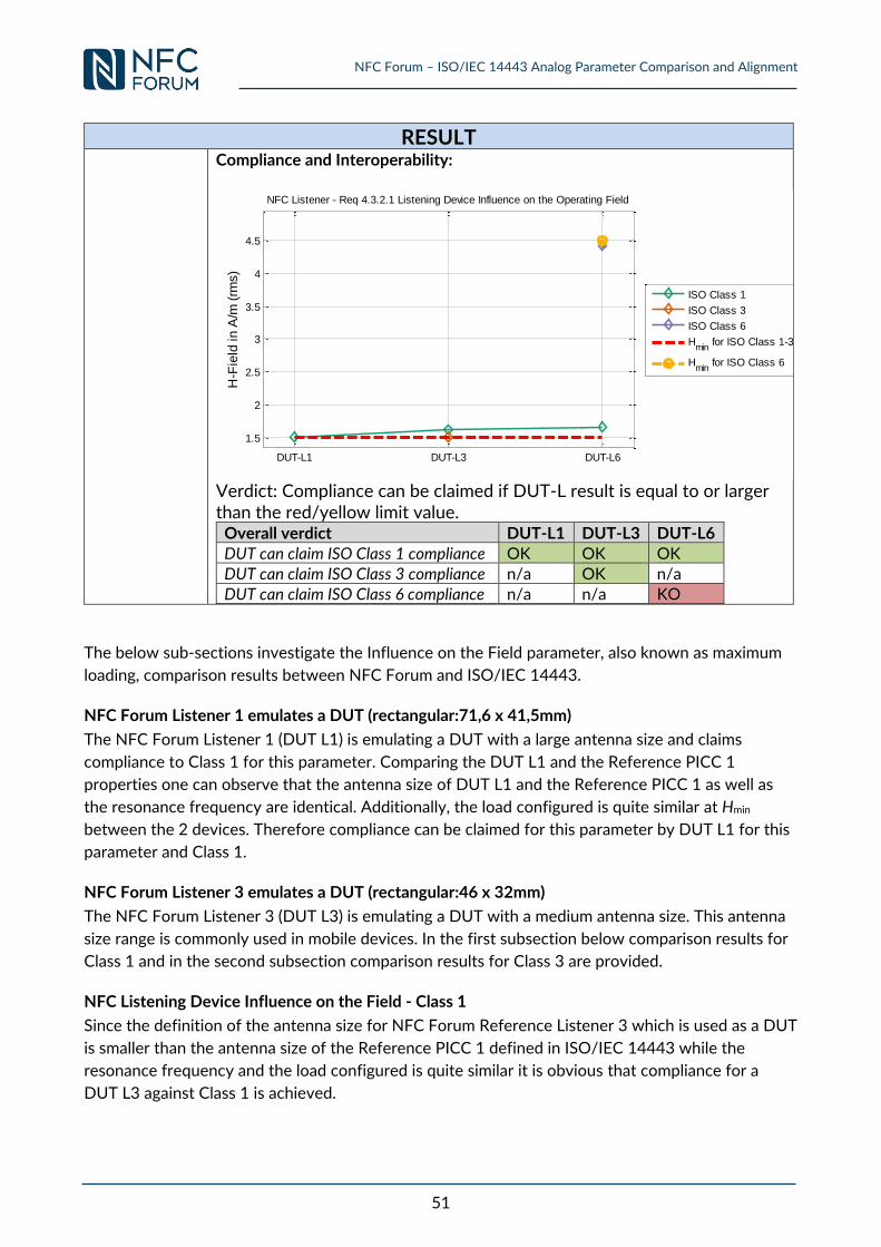
NFC Forum – ISO/IEC 14443 Analog Parameter Comparison and Alignment
51
RESULT
Compliance and Interoperability:
Verdict: Compliance can be claimed if DUT-L result is equal to or larger than the red/yellow limit value.
Overall verdict DUT-L1 DUT-L3 DUT-L6
DUT can claim ISO Class 1 compliance OK OK OK DUT can claim ISO Class 3 compliance n/a OK n/a DUT can claim ISO Class 6 compliance n/a n/a KO
The below sub-sections investigate the Influence on the Field parameter, also known as maximum
loading, comparison results between NFC Forum and ISO/IEC 14443.
NFC Forum Listener 1 emulates a DUT (rectangular:71,6 x 41,5mm)
The NFC Forum Listener 1 (DUT L1) is emulating a DUT with a large antenna size and claims
compliance to Class 1 for this parameter. Comparing the DUT L1 and the Reference PICC 1
properties one can observe that the antenna size of DUT L1 and the Reference PICC 1 as well as
the resonance frequency are identical. Additionally, the load configured is quite similar at Hmin
between the 2 devices. Therefore compliance can be claimed for this parameter by DUT L1 for this
parameter and Class 1.
NFC Forum Listener 3 emulates a DUT (rectangular:46 x 32mm)
The NFC Forum Listener 3 (DUT L3) is emulating a DUT with a medium antenna size. This antenna
size range is commonly used in mobile devices. In the first subsection below comparison results for
Class 1 and in the second subsection comparison results for Class 3 are provided.
NFC Listening Device Influence on the Field - Class 1
Since the definition of the antenna size for NFC Forum Reference Listener 3 which is used as a DUT
is smaller than the antenna size of the Reference PICC 1 defined in ISO/IEC 14443 while the
resonance frequency and the load configured is quite similar it is obvious that compliance for a
DUT L3 against Class 1 is achieved.
DUT-L1 DUT-L3 DUT-L6
1.5
2
2.5
3
3.5
4
4.5H
-Fie
ld in
A/m
(rm
s)
NFC Listener - Req 4.3.2.1 Listening Device Influence on the Operating Field
ISO Class 1
ISO Class 3
ISO Class 6
Hmin
for ISO Class 1-3
Hmin
for ISO Class 6
NFC Forum – ISO/IEC 14443 Analog Parameter Comparison and Alignment
52
NFC Listening Device Influence on the Field - Class 3
The definition of the antenna size for NFC Forum Reference Listener 3, emulating DUT Listener 3,
equals the antenna size of the Reference PICC 3 defined in [ISO10373-6] and [ISO10373-6:AMD1].
Additionally the resonance frequency is equal and the configured load is quite similar. Therefore
compliance for a DUT L3 against Class 3 can be claimed.
NFC Forum Listener 6 emulates a DUT (rectangular:24,7 x 19,7mm)
The NFC Forum Listener 6 (DUT L6) is emulating a DUT with a small antenna size. This antenna size
range is commonly used within mobile devices. In the first subsection below comparison results for
Class 1 and in the second subsection comparison results for Class 6 are provided.
NFC Listening Device Influence on the Field - Class 1
Since the definition of the antenna size for NFC Forum Reference Listener 6 which is used as a DUT
is smaller than the antenna size of the Reference PICC 1 defined in ISO/IEC 14443 while the
resonance frequency and the load configured is quite similar compliance for a DUT L6 against
Class 1 can be claimed.
NFC Listening Device Influence on the Field - Class 6
The definition of the antenna size for NFC Forum Reference Listener 6, emulating DUT L6, equals
the antenna size of the Reference PICC 6 defined in [ISO10373-6] and [ISO10373-6:AMD1].
Additionally the resonance frequency settings are equal and the configured load is quite similar. The
measurement results show a difference for this parameter and a slightly higher loading of DUT
Listener 6 compared to the loading of the Reference PICC 6. Since this difference is very low it can
be considered as measurement uncertainty. Therefore compliance for a DUT L6 against Class 6 can
be claimed.
Summary and Recommendations
Compliance can be claimed for all considered sizes of DUT antennas according to NFC Forum
against the Class 1 (including "no Class") as defined by ISO/IEC 14443 additionally to the
compliance to the claimed Class. No further actions required.
3.2.3 Requirement 4.5.2.1: Carrier Frequency fc (Listening Device Reception)
CONTEXT
Reference [NFC_ANA]
Requirement 4.5.2.1 When placed in the Operating Volume of the NFC Forum – Reference Polling Device, the Listening Device SHALL function properly with a carrier frequency between the Min and Max values of fS,C as defined in Appendix B.3, being generated by the NFC Forum – Reference Polling Device
Implicit Requirement
Carrier Frequency Generation
Question Is an NFC Forum Device in Listen mode which is compliant for the above Carrier Frequency requirement also compliant or interoperable to the corresponding ISO Requirement?
CONCLUSION / DISCUSSION
For a comparison on specification level refer to 0) B.4. ISO/IEC 14443-2 PICC Requirement for the Carrier Frequency fc
NFC Forum – ISO/IEC 14443 Analog Parameter Comparison and Alignment
53
No experimental measurement needed.
3.2.4 Requirement 4.6.2.1: Power On (Listening Device Reception)
CONTEXT
Reference [NFC_ANA]
Requirement 4.6.2.1 If a Listening Device in NO_REMOTE_FIELD state is placed in the Operating Volume of the NFC Forum – Reference Polling Device set-up to be between the Min and Max power levels of Operating Field that may be provided by a Polling Device, it SHALL enter the IDLE state within a time GTA, GTB, and GTF. Refer to [DIGITAL] for the values of GTA, GTB and GTF. Refer to [ACTIVITY] for details on the NO_REMOTE_FIELD and IDLE states.
Implicit Requirement
Startup Time for a Listener to enter IDLE State
Question Is an NFC Forum Device in Listen mode which is compliant for the above requirement also compliant or interoperable to the corresponding ISO PICC Requirement?
CONCLUSION / DISCUSSION
This parameter is defined in [NFC_ACTIVITY] and therefore is not of relevance for this analog parameter comparison. No experimental measurements needed.
3.2.5 Requirements 4.8.2.1: Listening Device Reset (Listening Device
Reception)
a. tFIELD OFF
CONTEXT
Reference [NFC_ANA]
Requirement 4.7.2.1 When the NFC Forum - Reference Listening Device is within the Operating Volume of the Polling Device and the Polling Device resets the Operating Field, it SHALL generate a voltage less than or equal to Max V0V,RESET (rms) for a time tFIELD_OFF defined by [ACTIVITY], characterized at the output of the sense coil on J4 of the NFC Forum - Reference Listening Device.
Implicit Requirement
Time for a Listener to enter NO_REMOTE_FIELD State
Question Is an NFC Forum Device in Listen mode which is compliant for the above requirement also compliant or interoperable to the corresponding ISO PICC Requirement?
CONCLUSION / DISCUSSION
This parameter is defined in [NFC_ACTIVITY] and therefore of no relevance for this analog parameter comparison. No experimental measurements needed.
b. VOV,RESET
CONTEXT
NFC Forum – ISO/IEC 14443 Analog Parameter Comparison and Alignment
54
Reference [NFC_ANA]
Requirement 4.8.2.1 When the Operating Field is switched off as simulated by the signal generator level being reduced from VGEN,MINIMUM to VGEN,RESET for a time tFIELD_OFF defined by [ACTIVITY], a Listening Device SHALL enter NO_REMOTE_FIELD state as defined by [ACTIVITY]. After the signal level is restored back to VGEN,MINIMUM, the Listening Device MUST be in IDLE state after a time GTA, GTB and GTF.
Implicit Requirement
Residual amplitude verification
Question Is an NFC Forum Device in Listen mode which is compliant for the above maximum reset voltage reception requirement also compliant or interoperable to the corresponding ISO PICC Requirement?
CONCLUSION / DISCUSSION There is no such Requirement in [ISO14443-2] . No experimental Measurements
needed.
3.2.6 Requirement 5.2.2.1: Modulation Polling Device to Listening Device –
NFC-A (Listening Device Reception)
CONTEXT
Reference [NFC_ANA]
Requirement 5.2.2.1: When placed in the Operating Volume of the NFC Forum – Reference Polling Device, a Listening Device of NFC-A SHALL function properly when the NFC Forum – Reference Polling Device has been set up as described in the specification context above.
Implicit Requirement
NFC-A Listener wave shape reception
Question Is an NFC Forum Device in Listen mode which is compliant for the above NFC-A wave shape reception requirement also compliant or interoperable to the corresponding ISO PICC Requirement?
CONCLUSION / DISCUSSION
See section 3.1.5 for further information
3.2.7 Requirement 5.4.2.1: Modulation Polling Device to Listening Device –
NFC-B (Listening Device Reception)
CONTEXT
Reference [NFC_ANA]
Requirement 5.4.2.1: When placed in the Operating Volume of the NFC Forum – Reference Polling Device, a Listening Device of NFC-B SHALL function properly when the NFC Forum – Reference Polling Device has been set up as described in the specification context above.
Implicit Requirement
NFC-A Listener wave shape reception
NFC Forum – ISO/IEC 14443 Analog Parameter Comparison and Alignment
55
Question Is an NFC Forum Device in Listen mode which is compliant for the above NFC-B wave shape reception requirement also compliant or interoperable to the corresponding ISO PICC Requirement?
CONCLUSION / DISCUSSION
See section 3.1.6 for further information
3.2.8 Requirement 5.6.2.1: Modulation Polling Device to Listening Device –
NFC-F (Listening Device Reception)
No experimental measurement needed.
3.2.9 Requirement 6.1.2.1 & 6.1.2.2 & 6.2.3.3: Load Modulation
Characteristics – Generic (Listening Device Transmission)
a. Subcarrier Frequency No experimental measurement needed.
b. VPP,min
CONTEXT
Reference [NFC_ANA]
Requirement 6.1.2.1-6.1.2.3: When put in the Operating Volume of the NFC Forum – Reference Polling Device that has been set up as described in the specification context above, the Listening Device SHALL modulate the Operating Field in such a way that the signal monitored at J2 of the NFC Forum – Reference Polling Device has the following characteristics: 6.1.2.1 The subcarrier frequency fs of the modulation signal SHALL be fc/16 for NFC-A and NFC-B. 6.1.2.2 For NFC-F, the frequency fs of the modulation signal during the preamble SHALL be fc/32 or fc/64 and SHALL be fc/32, fc/64 or fc/128 (see note 1) at other times. 6.1.2.3 The amplitude (Vpp) of the modulation signal at J2 of the NFC Forum – Reference Polling Device SHALL be Vpp (peak to peak). (Choosing a measurement position avoiding all transient effects, e.g., the first change from 0 to 1 for NFC-A, the TR1 zone for NFC-B and the zero coding preamble before the Sync code for NFC-F).
Implicit Requirement
Minimum load modulation amplitude transmission
Question Is an NFC Forum Device in Listen mode which is compliant for the above minimum load modulation transmission requirement also compliant or interoperable to the corresponding minimum ISO PICC Requirement?
PROCEDURE Step SETUP
1 Setup the NFC Forum – Reference Poller 0 to nominal field strength (VS,OV,nom).
2 Setup the DUT L1 (loading 330Ω) in order to get listener minimum load
modulation value in each position of the NFC OV when measured at the J2 output of the NFC Forum – Reference Poller 0.
NFC Forum – ISO/IEC 14443 Analog Parameter Comparison and Alignment
56
Topic Parameter Coil Value
Units Min
Load Modulation
Poller←Listener Vpp Poller-0 20 mVpp
Record VOV (loading 330Ω) and the load modulator input voltage for each
position of the NFC OV.
3 Setup the NFC Forum – Reference Poller 3 to nominal field strength (VS,OV,nom).
4
Setup the DUT L1 (loading 330Ω) in order to get listener minimum load
modulation value in each position of the NFC OV when measured at the J2 output of the NFC Forum – Reference Poller 3.
Topic Parameter Coil Value
Units Min
Load Modulation
Poller←Listener Vpp Poller-3 9.5 mVpp
Record VOV (loading 330Ω) and the load modulator input voltage for each
position of the NFC OV. 5 Setup the NFC Forum – Reference Poller 6 to nominal field strength.
6
Setup the DUT L1 (loading 330Ω) in order to get listener minimum load
modulation value in each position of the NFC OV when measured at the J2 output of the NFC Forum – Reference Poller 6.
Topic Parameter Coil Value
Units Min
Load Modulation
Poller←Listener Vpp Poller-
6 7 mVpp
Record VOV (loading 330Ω) and the load modulator input voltage for each
position of the NFC OV. 7 Repeat the procedure above with DUT L3 and DUT L6.
Step VERIFICATION 1 Place DUT L1 in the DUT position of the respective Test PCD Assembly.
2 Readjust the field strength until the VOV as measured at DUT L1 in each of the NFC Forum – Reference Poller test positions is reached.
3 Set the load modulator input voltage for the position (SETUP Steps 2), 4) and 6)) and measure the load modulation amplitude.
4 Repeat the VERIFICATION steps with DUT L3 and DUT L6.
5
Repeat the complete SETUP and VERIFICATION steps with max VS,OV in SETUP steps 1, 3 and 5. Note: This analysis assumes the NFC Forum Analog specification defines the Load
modulation amplitude limits independent of position within the NFC OV and field strength.
NFC Forum – ISO/IEC 14443 Analog Parameter Comparison and Alignment
57
EXPECTED OUTCOME
Step COMPLIANCY
1 Compare the measured load modulation amplitude of VERIFICATION step 3 to the ISO PICC minimum load modulation amplitude (see Table
27).
Step INTEROPERABILITY
1 Compare the measured load modulation amplitude of VERIFICATION step 3 to the ISO PCD minimum load modulation amplitude (see Table
24).
The below sub-sections analyze the minimum load modulation amplitude parameter comparison
results, between NFC Forum and ISO/IEC 14443.
Compliance and interoperability evaluation are performed for Class 1, Class 2 and Class 3 as
defined by ISO/IEC 14443. Since the support of these classes is mandatory for PCDs compliant to
[CEN/TS 16794-1] and [ISO14443-2] interoperability to one of these classes is the goal. For
DUT L6 compliance and interoperability is verified additionally for Class 6.
NFC Forum Listener 1 emulates a DUT (rectangular:71,6 x 41,5mm)
The NFC Forum Listener 1 (DUT L1) is emulating a DUT with the largest considered antenna size. In
the subsection below comparison results for compliance/interoperability to Class 1-3 is given.
Compliance to other classes is not applicable.
DUT L1 min LMA (VPP, min) and PICC class 1 compliance and interoperability
Figure 13 shows the field strength versus side band amplitude graph. Each black pair of points (*
and Diamond) corresponds to one measurement position of DUT L1 on Reference P0, P3 and P6,
transformed to equivalent field strength on the ISO Test PCD Assembly 1 with its related sideband
amplitude. The red dashed line denotes the minimum PICC limit, relevant for compliance, while the
red dotted line depicts the minimum PCD limit, relevant for interoperability for this parameter. For
interoperability the side band amplitude level for each field strength should be equal to or above
the PCD limit curve, for compliance equal to or above the PICC limit curve.
Compliance/Interoperability of DUT L1 against Class 1 Class 2 and Class 3 can only be claimed for a
field strength higher than 4,5A/m.
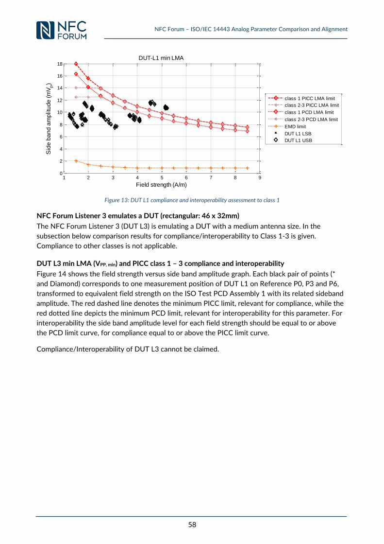
NFC Forum – ISO/IEC 14443 Analog Parameter Comparison and Alignment
58
Figure 13: DUT L1 compliance and interoperability assessment to class 1
NFC Forum Listener 3 emulates a DUT (rectangular: 46 x 32mm)
The NFC Forum Listener 3 (DUT L3) is emulating a DUT with a medium antenna size. In the
subsection below comparison results for compliance/interoperability to Class 1-3 is given.
Compliance to other classes is not applicable.
DUT L3 min LMA (VPP, min) and PICC class 1 – 3 compliance and interoperability
Figure 14 shows the field strength versus side band amplitude graph. Each black pair of points (*
and Diamond) corresponds to one measurement position of DUT L1 on Reference P0, P3 and P6,
transformed to equivalent field strength on the ISO Test PCD Assembly 1 with its related sideband
amplitude. The red dashed line denotes the minimum PICC limit, relevant for compliance, while the
red dotted line depicts the minimum PCD limit, relevant for interoperability for this parameter. For
interoperability the side band amplitude level for each field strength should be equal to or above
the PCD limit curve, for compliance equal to or above the PICC limit curve.
Compliance/Interoperability of DUT L3 cannot be claimed.
1 2 3 4 5 6 7 8 90
2
4
6
8
10
12
14
16
18
Field strength (A/m)
Sid
e b
an
d a
mp
litu
de
(m
VP)
DUT-L1 min LMA
class 1 PICC LMA limit
class 2-3 PICC LMA limit
class 1 PCD LMA limit
class 2-3 PCD LMA limit
EMD limit
DUT L1 LSB
DUT L1 USB

NFC Forum – ISO/IEC 14443 Analog Parameter Comparison and Alignment
59
Figure 14: DUT L3 and compliance assessment to class 1-3
NFC Forum Listener 6 emulates a DUT (rectangular: 24,7 x 19,7mm)
The NFC Forum Listener 6 (DUT L6) is emulating a DUT with a small antenna size. In the first
subsection below comparison results for compliance/interoperability to Class 1-3 is given. The
second subsection shows results for compliance/interoperability to Class 6
DUT L6 min LMA (VPP, min) and PICC class 1 – 3 and 6 compliance and interoperability
Figure 15 shows the field strength versus side band amplitude graph. Each black pair of points (*
and Diamond) corresponds to one measurement position of DUT L1 on Reference P0, P3 and P6,
transformed to equivalent field strength on the ISO Test PCD Assembly 1 with its related sideband
amplitude. The red dashed line denotes the minimum PICC limit, relevant for compliance, while the
red dotted line depicts the minimum PCD limit, relevant for interoperability for this parameter. For
interoperability the side band amplitude level for each field strength should be equal to or above
the PCD limit curve, for compliance equal to or above the PICC limit curve.
Neither compliance nor interoperability of DUT L6 can be claimed to Class 1-3.
1 2 3 4 5 6 7 8 90
2
4
6
8
10
12
14
16
18
Field strength (A/m)
Sid
e b
an
d a
mp
litu
de
(m
VP)
DUT-L3 min LMA
class 1 PICC LMA limit
class 2-3 PICC LMA limit
class 1 PCD LMA limit
class 2-3 PCD LMA limit
EMD limit
DUT L3 LSB
DUT L3 USB
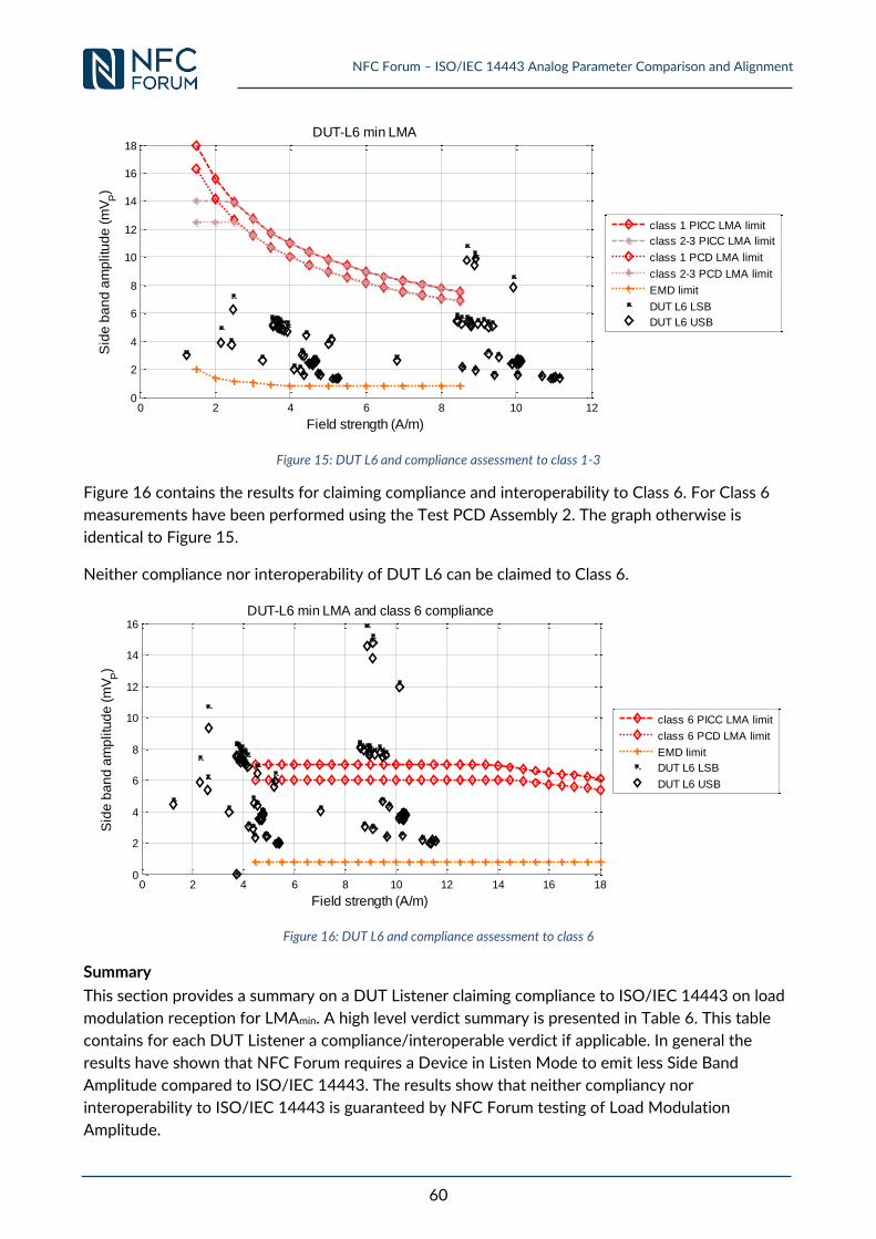
NFC Forum – ISO/IEC 14443 Analog Parameter Comparison and Alignment
60
Figure 15: DUT L6 and compliance assessment to class 1-3
Figure 16 contains the results for claiming compliance and interoperability to Class 6. For Class 6
measurements have been performed using the Test PCD Assembly 2. The graph otherwise is
identical to Figure 15.
Neither compliance nor interoperability of DUT L6 can be claimed to Class 6.
Figure 16: DUT L6 and compliance assessment to class 6
Summary
This section provides a summary on a DUT Listener claiming compliance to ISO/IEC 14443 on load
modulation reception for LMAmin. A high level verdict summary is presented in Table 6. This table
contains for each DUT Listener a compliance/interoperable verdict if applicable. In general the
results have shown that NFC Forum requires a Device in Listen Mode to emit less Side Band
Amplitude compared to ISO/IEC 14443. The results show that neither compliancy nor
interoperability to ISO/IEC 14443 is guaranteed by NFC Forum testing of Load Modulation
Amplitude.
0 2 4 6 8 10 120
2
4
6
8
10
12
14
16
18
Field strength (A/m)
Sid
e b
an
d a
mp
litu
de
(m
VP)
DUT-L6 min LMA
class 1 PICC LMA limit
class 2-3 PICC LMA limit
class 1 PCD LMA limit
class 2-3 PCD LMA limit
EMD limit
DUT L6 LSB
DUT L6 USB
0 2 4 6 8 10 12 14 16 180
2
4
6
8
10
12
14
16
Field strength (A/m)
Sid
e b
an
d a
mp
litu
de
(m
VP)
DUT-L6 min LMA and class 6 compliance
class 6 PICC LMA limit
class 6 PCD LMA limit
EMD limit
DUT L6 LSB
DUT L6 USB
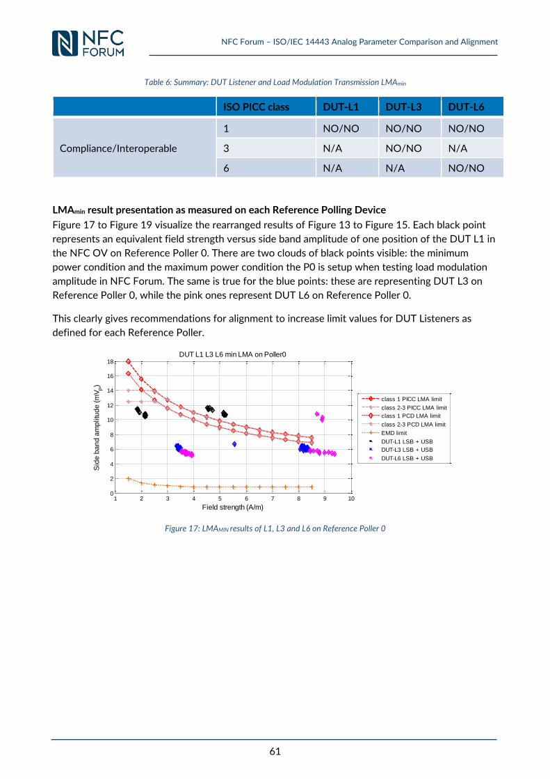
NFC Forum – ISO/IEC 14443 Analog Parameter Comparison and Alignment
61
Table 6: Summary: DUT Listener and Load Modulation Transmission LMAmin
ISO PICC class DUT-L1 DUT-L3 DUT-L6
Compliance/Interoperable
1 NO/NO NO/NO NO/NO
3 N/A NO/NO N/A
6 N/A N/A NO/NO
LMAmin result presentation as measured on each Reference Polling Device
Figure 17 to Figure 19 visualize the rearranged results of Figure 13 to Figure 15. Each black point
represents an equivalent field strength versus side band amplitude of one position of the DUT L1 in
the NFC OV on Reference Poller 0. There are two clouds of black points visible: the minimum
power condition and the maximum power condition the P0 is setup when testing load modulation
amplitude in NFC Forum. The same is true for the blue points: these are representing DUT L3 on
Reference Poller 0, while the pink ones represent DUT L6 on Reference Poller 0.
This clearly gives recommendations for alignment to increase limit values for DUT Listeners as
defined for each Reference Poller.
Figure 17: LMAMIN results of L1, L3 and L6 on Reference Poller 0
1 2 3 4 5 6 7 8 9 100
2
4
6
8
10
12
14
16
18
Field strength (A/m)
Sid
e b
an
d a
mp
litu
de
(m
VP)
DUT L1 L3 L6 min LMA on Poller0
class 1 PICC LMA limit
class 2-3 PICC LMA limit
class 1 PCD LMA limit
class 2-3 PCD LMA limit
EMD limit
DUT-L1 LSB + USB
DUT-L3 LSB + USB
DUT-L6 LSB + USB
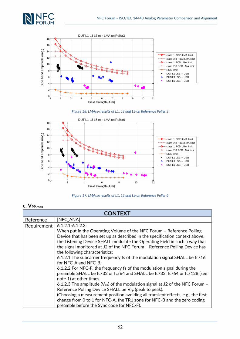
NFC Forum – ISO/IEC 14443 Analog Parameter Comparison and Alignment
62
Figure 18: LMAMIN results of L1, L3 and L6 on Reference Poller 3
Figure 19: LMAMIN results of L1, L3 and L6 on Reference Poller 6
c. VPP,max
CONTEXT
Reference [NFC_ANA]
Requirement 6.1.2.1-6.1.2.3: When put in the Operating Volume of the NFC Forum – Reference Polling Device that has been set up as described in the specification context above, the Listening Device SHALL modulate the Operating Field in such a way that the signal monitored at J2 of the NFC Forum – Reference Polling Device has the following characteristics: 6.1.2.1 The subcarrier frequency fs of the modulation signal SHALL be fc/16 for NFC-A and NFC-B. 6.1.2.2 For NFC-F, the frequency fs of the modulation signal during the preamble SHALL be fc/32 or fc/64 and SHALL be fc/32, fc/64 or fc/128 (see note 1) at other times. 6.1.2.3 The amplitude (Vpp) of the modulation signal at J2 of the NFC Forum – Reference Polling Device SHALL be Vpp (peak to peak). (Choosing a measurement position avoiding all transient effects, e.g., the first change from 0 to 1 for NFC-A, the TR1 zone for NFC-B and the zero coding preamble before the Sync code for NFC-F).
1 2 3 4 5 6 7 8 9 10 110
2
4
6
8
10
12
14
16
18
Field strength (A/m)
Sid
e b
an
d a
mp
litu
de
(m
VP)
DUT L1 L3 L6 min LMA on Poller3
class 1 PICC LMA limit
class 2-3 PICC LMA limit
class 1 PCD LMA limit
class 2-3 PCD LMA limit
EMD limit
DUT-L1 LSB + USB
DUT-L3 LSB + USB
DUT-L6 LSB + USB
0 2 4 6 8 10 120
2
4
6
8
10
12
14
16
18
Field strength (A/m)
Sid
e b
an
d a
mp
litu
de
(m
VP)
DUT L1 L3 L6 min LMA on Poller6
class 1 PICC LMA limit
class 2-3 PICC LMA limit
class 1 PCD LMA limit
class 2-3 PCD LMA limit
EMD limit
DUT-L1 LSB + USB
DUT-L3 LSB + USB
DUT-L6 LSB + USB
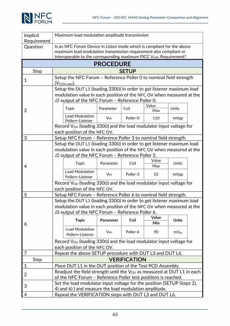
NFC Forum – ISO/IEC 14443 Analog Parameter Comparison and Alignment
63
Implicit Requirement
Maximum load modulation amplitude transmission
Question Is an NFC Forum Device in Listen mode which is compliant for the above maximum load modulation transmission requirement also compliant or interoperable to the corresponding maximum PICC VLMA Requirement?
PROCEDURE Step SETUP
1 Setup the NFC Forum – Reference Poller 0 to nominal field strength (VS,OV,nom).
2
Setup the DUT L1 (loading 330Ω) in order to get listener maximum load
modulation value in each position of the NFC OV when measured at the J2 output of the NFC Forum – Reference Poller 0.
Topic Parameter Coil Value
Units Max
Load Modulation Poller←Listener
VPP Poller-0 110 mVpp
Record VOV (loading 330Ω) and the load modulator input voltage for
each position of the NFC OV.
3 Setup NFC Forum – Reference Poller 3 to nominal field strength.
4
Setup the DUT L1 (loading 330Ω) in order to get listener maximum load
modulation value in each position of the NFC OV when measured at the J2 output of the NFC Forum – Reference Poller 3.
Topic Parameter Coil Value
Units Max
Load Modulation
Poller←Listener VPP Poller-3 53 mVpp
Record VOV (loading 330Ω) and the load modulator input voltage for
each position of the NFC OV.
5 Setup NFC Forum – Reference Poller 6 to nominal field strength.
6
Setup the DUT L1 (loading 330Ω) in order to get listener maximum load
modulation value in each position of the NFC OV when measured at the J2 output of the NFC Forum – Reference Poller 6.
Topic Parameter Coil Value
Units Min
Load Modulation
Poller←Listener VPP Poller-6 90 mVpp
Record VOV (loading 330Ω) and the load modulator input voltage for
each position of the NFC OV. 7 Repeat the above SETUP procedure with DUT L3 and DUT L6.
Step VERIFICATION 1 Place DUT L1 in the DUT position of the Test PCD Assembly.
2 Readjust the field strength until the VOV as measured at DUT L1 in each of the NFC Forum – Reference Poller test positions is reached.
3 Set the load modulator input voltage for the position (SETUP Steps 2), 4) and 6) ) and measure the load modulation amplitude.
4 Repeat the VERIFICATION steps with DUT L3 and DUT L6.
NFC Forum – ISO/IEC 14443 Analog Parameter Comparison and Alignment
64
5
Repeat the complete SETUP and VERIFICATION steps with max VS,OV in SETUP steps 1, 3 and 5. Note: This analysis assumes the NFC Forum Analog specification defines the Load
modulation amplitude limits independent of position within the NFC OV and field strength.
EXPECTED OUTCOME
Step COMPLIANCY
1 Compare the measured load modulation amplitude of VERIFICATION step 3 to the ISO PICC maximum load modulation amplitude (see 00)c.
VPP,max in process in WG8).
Step INTEROPERABILITY
1 Compare the measured load modulation amplitude of VERIFICATION step 3 to the ISO PCD maximum load modulation amplitude (see 0 0)b.
VPP,max in process in WG8).
3.2.10 Requirements 6.2.1.1 & 6.2.1.2: Load Modulation Characteristics
– NFC-A (Listening Device Transmission)
CONTEXT
Reference [NFC_ANA]
Requirement 6.2.1.1 A Listening Device of NFC-A SHALL modulate the subcarrier using On-Off Keying (OOK). 6.2.1.2 When modulating the subcarrier, a Listening Device of NFC-A SHALL only start the bit period on the rising or falling edge of the subcarrier so that the modulation starts with a defined phase relationship to the subcarrier.
Implicit Requirement
NFC-A subcarrier Load Modulation Characteristics
Question Is an NFC Forum Device in Listen mode which is compliant for the above NFC-A load modulation characteristics requirement also compliant or interoperable to the corresponding ISO PICC Requirement?
CONCLUSION / DISCUSSION
No Difference from specification point of view No experimental measurement needed.
3.2.11 Requirements 6.3.1.1 & 6.3.1.3: Load Modulation Characteristics
– NFC-B (Listening Device Transmission)
CONTEXT
Reference [NFC_ANA]
Requirement 6.3.1.1 A Listening Device of NFC-B SHALL modulate the subcarrier using BPSK. 6.3.1.2 A Listening Device of NFC-B SHALL generate a subcarrier only when data is to be transmitted. 6.3.1.3 Phase shifts SHALL only occur at nominal positions of rising or falling edges of the subcarrier.
Implicit Requirement
NFC-B subcarrier Load Modulation Characteristics
NFC Forum – ISO/IEC 14443 Analog Parameter Comparison and Alignment
65
Question Is an NFC Forum Device in Listen mode which is compliant for the above NFC-B load modulation characteristics requirement also compliant or interoperable to the corresponding ISO PICC Requirement?
CONCLUSION / DISCUSSION
No Difference from specification point of view No experimental measurement needed.
3.2.12 Requirement 6.4.1.1: Load Modulation Characteristics – NFC-F
(Listening Device Transmission)
CONTEXT
Reference [NFC_ANA]
Requirement 6.4.1.1 A Listening Device of NFC-F SHALL load modulate the carrier using Amplitude Shift Keying (ASK).
Implicit Requirement
NFC-F subcarrier Load Modulation Characteristics
Question Is an NFC Forum Device in Listen mode which is compliant for the above NFC-B load modulation characteristics requirement also compliant or interoperable to the corresponding ISO PICC Requirement?
CONCLUSION / DISCUSSION
No difference from specification point of view No experimental measurement needed.
NFC Forum – ISO/IEC 14443 Analog Parameter Comparison and Alignment
66
4 Limit Harmonization and Validation In the previous section a generic status quo assessment for analogue parameter limits between NFC
Forum and ISO/IEC 14443 has been performed taking into account the Public Transport application
profile is defined in [CEN/TS 16794-1]. The comparison of results in combination with an
interpretation, as well as a relevance analysis, finally led to the identification of parameter limits
differences with potential interoperability risks. For these identified parameter limits, this section
discusses options for harmonization. For the selected option harmonization proposals are
developed and proposed. Once a solution for harmonization was found. e.g. a new limit value has
been determined, an adequate validation is performed.
Amongst the analysed parameter limits the following resulted in differences which are relevant for
interoperability of mobile devices in legacy infrastructures and with legacy PICCs:
Polling Device minimum power requirement VOV, min versus ISO/IEC PCD requirement for
Hmin
Listening Device LMAmin requirement VPP, min versus ISO/IEC PICC requirement for LMAmin
(VLMA, PICC)
4.1 NFC Forum Polling Device VOV,min Harmonization and
Validation
For the harmonization of the minimum field strength parameter the following process was followed.
First an evaluation of different options for harmonization was performed. Second, for the selected
option the methodology and procedure have been defined. Third, the measurements have been
performed and reviewed accordingly. In case a suitability analysis was passed successfully the
validation of the new candidate limit was performed.
The following options to align the minimum field strength requirement between NFC Forum and
ISIO/IEC 14443 (with PT focus) have been discussed between the experts:
(1) Increase minimum field strength requirement defined by NFC Forum
(2) Decrease the Hmin requirement as defined in ISO/IEC 14443. This however, would need the
support of ISO WG 8
(3) Indirect increase of field strength requirement by increasing the operating volume in NFC
Forum
(4) Addition of a certification track with increased Hmin power requirements in NFC Forum.
(5) any combination of above listed options
All experts involved in the decision process clearly preferred the harmonization option (1), that NFC
Forum should increase the minimum field strength requirement. This step would globally improve
interoperability to all standards bodies defining the 13.56 MHz radio.
The harmonization for Hmin was split into two distinct analysis. The first harmonization approach
performs harmonization based on a homogenous field condition. This is achieved by performing the
harmonization on the Test PCD Assembly as defined in [ISO10373-6]. In contrast, the second
harmonization approach performs harmonization looking at the real situation in the field. This is
well reflected by the Polling Device power transmission and PCD field strength test cases defined
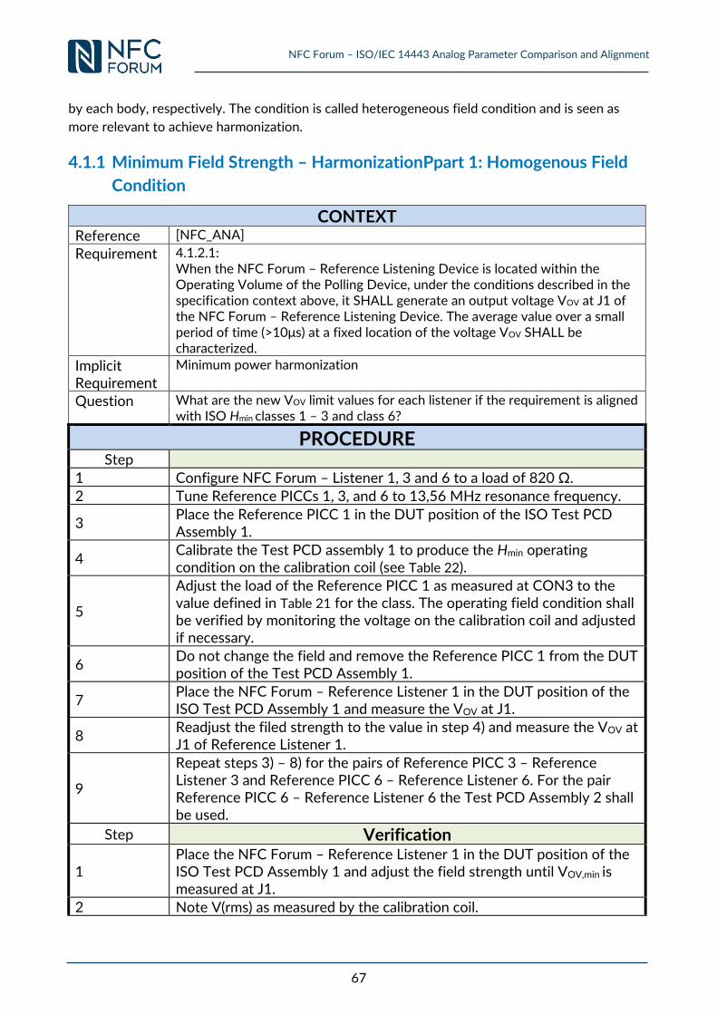
NFC Forum – ISO/IEC 14443 Analog Parameter Comparison and Alignment
67
by each body, respectively. The condition is called heterogeneous field condition and is seen as
more relevant to achieve harmonization.
4.1.1 Minimum Field Strength – HarmonizationPpart 1: Homogenous Field
Condition
CONTEXT
Reference [NFC_ANA]
Requirement 4.1.2.1: When the NFC Forum – Reference Listening Device is located within the Operating Volume of the Polling Device, under the conditions described in the specification context above, it SHALL generate an output voltage VOV at J1 of the NFC Forum – Reference Listening Device. The average value over a small period of time (>10μs) at a fixed location of the voltage VOV SHALL be characterized.
Implicit Requirement
Minimum power harmonization
Question What are the new VOV limit values for each listener if the requirement is aligned with ISO Hmin classes 1 – 3 and class 6?
PROCEDURE Step
1 Configure NFC Forum – Listener 1, 3 and 6 to a load of 820 Ω.
2 Tune Reference PICCs 1, 3, and 6 to 13,56 MHz resonance frequency.
3 Place the Reference PICC 1 in the DUT position of the ISO Test PCD Assembly 1.
4 Calibrate the Test PCD assembly 1 to produce the Hmin operating condition on the calibration coil (see Table 22).
5
Adjust the load of the Reference PICC 1 as measured at CON3 to the value defined in Table 21 for the class. The operating field condition shall be verified by monitoring the voltage on the calibration coil and adjusted if necessary.
6 Do not change the field and remove the Reference PICC 1 from the DUT position of the Test PCD Assembly 1.
7 Place the NFC Forum – Reference Listener 1 in the DUT position of the ISO Test PCD Assembly 1 and measure the VOV at J1.
8 Readjust the filed strength to the value in step 4) and measure the VOV at J1 of Reference Listener 1.
9
Repeat steps 3) – 8) for the pairs of Reference PICC 3 – Reference Listener 3 and Reference PICC 6 – Reference Listener 6. For the pair Reference PICC 6 – Reference Listener 6 the Test PCD Assembly 2 shall be used.
Step Verification
1 Place the NFC Forum – Reference Listener 1 in the DUT position of the ISO Test PCD Assembly 1 and adjust the field strength until VOV,min is measured at J1.
2 Note V(rms) as measured by the calibration coil.
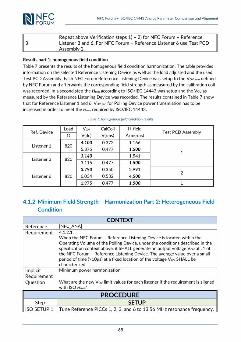
NFC Forum – ISO/IEC 14443 Analog Parameter Comparison and Alignment
68
3 Repeat above Verification steps 1) – 2) for NFC Forum – Reference Listener 3 and 6. For NFC Forum – Reference Listener 6 use Test PCD Assembly 2.
Results part 1: homogenous field condition
Table 7 presents the results of the homogenous field condition harmonization. The table provides
information on the selected Reference Listening Device as well as the load adjusted and the used
Test PCD Assembly. Each NFC Forum Reference Listening Device was setup to the VOV, min defined
by NFC Forum and afterwards the corresponding field strength as measured by the calibration coil
was recorded. In a second step the Hmin according to ISO/IEC 14443 was setup and the VOV as
measured by the Reference Listening Device was recorded. The results contained in Table 7 show
that for Reference Listener 1 and 6, VOV,min for Polling Device power transmission has to be
increased in order to meet the Hmin required by ISO/IEC 14443.
Table 7: homogenous field condition results
Ref. Device Load VOV CalCoil H-field
Test PCD Assembly Ω V(dc) V(rms) A/m(rms)
Listener 1 820 4.100 0.372 1.166
1 5.375 0.477 1.500
Listener 3 820 3.140 1.541
3.115 0.477 1.500
Listener 6 820
3.790 0.350 2.991 2
6.034 0.532 4.500
1.975 0.477 1.500 1
4.1.2 Minimum Field Strength – Harmonization Part 2: Heterogeneous Field
Condition
CONTEXT
Reference [NFC_ANA]
Requirement 4.1.2.1: When the NFC Forum – Reference Listening Device is located within the Operating Volume of the Polling Device, under the conditions described in the specification context above, it SHALL generate an output voltage VOV at J1 of the NFC Forum – Reference Listening Device. The average value over a small period of time (>10μs) at a fixed location of the voltage VOV SHALL be characterized.
Implicit Requirement
Minimum power harmonization
Question What are the new VOV limit values for each listener if the requirement is aligned with ISO Hmin?
PROCEDURE Step SETUP
ISO SETUP 1 Tune Reference PICCs 1, 2, 3, and 6 to 13,56 MHz resonance frequency.
NFC Forum – ISO/IEC 14443 Analog Parameter Comparison and Alignment
69
ISO SETUP 2
Place the Reference PICC into the DUT position of the Test PCD assembly 1 producing the Hmin (see Table 22) operating condition on the calibration coil. Measure Vload as defined in Table 21 at connector CON3. The operating field condition shall be verified by monitoring the voltage on the calibration coil and adjusted if necessary.
ISO SETUP 3 Repeat steps 2) – 4) for Reference PICCs 2, 3, and 6. Use Test PCD Assembly 2 for Reference PICC 6.
NFC SETUP 4
Setup DUT P0 in order to get Poller minimum field strength value measured with the Reference PICC 1, i.e., the measured CON3 value shall be equal to or larger than the value defined in Table 21 for the class, on at least one position of the NFC OV. Other positions shall give field strengths equal to or above the minimum defined for Reference PICC 1.
5
Measure the CON3 voltage V(dc) of Reference PICC 2 in the whole NFC OV of the DUT P0 and note the lowest value. If the value measured is less than the value defined in Table 21 for the class, increase the field strength to the value defined in Table 21 for this class, at this position.
6 Repeat Step 5 for Reference PICC 3 and 6.
Step VERIFICATION
1 Measure VDC output of each of the NFC Forum Reference Listening Devices in the whole NFC OV of the DUT P0 and note the lowest value measured.
2 Repeat this procedure with DUT P3 and DUT P6.
4.1.2.1 SETUP and VERIFICATION harmonization part 2: heterogeneous field
condition This section contains the results of the measurements performed according to the heterogeneous
field condition described in section 4.1.2. Table 8 contains the VOV [V(dc)] values as measured at J1
of the Reference Listening Devices for each DUT Polling device if setup is performed to be
compliant to exactly the Hmin limit defined by ISO/IEC 14443 for Class 1 - 3 and Class 6, i.e.
measured with Reference PICCs 1, 2, 3 and 6. This means for the setup using the Reference PICCs
at least in one position the minimum value Vload (see Table 21) is achieved and in all other positions
of the OV the same value or a value higher is measured. For DUT Poller 0 the worst case
counterpart was Reference PICC 1. For DUT Poller 3 the worst case counterpart was Reference
PICC 3. Finally, for DUT Poller 6 the worst case counterpart was Reference PICC 1. In order to
ensure interoperability on this parameter limit the minimum VOV, J1 value as measured by each
Listener on each DUT Poller in the OV is relevant. Therefore amongst the minimum VOV, J1
additionally the position information where this value was measured is provided. The position
information is encoded according to the NFC Forum definition (see [NFC_ANA], [NFC_TC_ANA])
except that the rotation index digit is not shown because constant. This minimum will be
automatically a candidate for new limits which achieves interoperability. In NFC Forum a DUT
Polling Device is required to pass the test cases using all 3 Reference Listening Devices.
Typically NFC Forum requirements and test cases are defined in such a way that each antenna size
of the Reference Equipment establishes the worst case for a DUT antenna size group. In case of the
VOV, min parameter, the best matching antenna size of the Reference Listener represent the worst
case situation for a DUT Poller or PCD. An analysis of the results contained in Table 8 show that
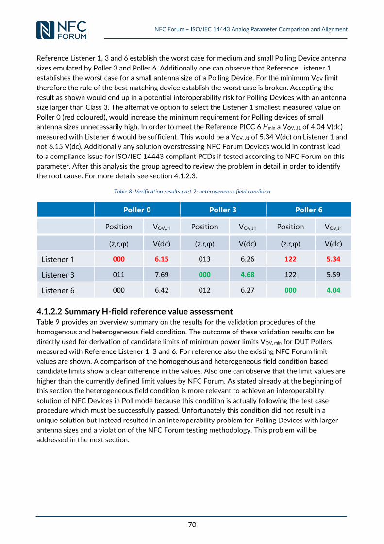
NFC Forum – ISO/IEC 14443 Analog Parameter Comparison and Alignment
70
Reference Listener 1, 3 and 6 establish the worst case for medium and small Polling Device antenna
sizes emulated by Poller 3 and Poller 6. Additionally one can observe that Reference Listener 1
establishes the worst case for a small antenna size of a Polling Device. For the minimum VOV limit
therefore the rule of the best matching device establish the worst case is broken. Accepting the
result as shown would end up in a potential interoperability risk for Polling Devices with an antenna
size larger than Class 3. The alternative option to select the Listener 1 smallest measured value on
Poller 0 (red coloured), would increase the minimum requirement for Polling devices of small
antenna sizes unnecessarily high. In order to meet the Reference PICC 6 Hmin a VOV, J1 of 4.04 V(dc)
measured with Listener 6 would be sufficient. This would be a VOV, J1 of 5.34 V(dc) on Listener 1 and
not 6.15 V(dc). Additionally any solution overstressing NFC Forum Devices would in contrast lead
to a compliance issue for ISO/IEC 14443 compliant PCDs if tested according to NFC Forum on this
parameter. After this analysis the group agreed to review the problem in detail in order to identify
the root cause. For more details see section 4.1.2.3.
Table 8: Verification results part 2: heterogeneous field condition
Poller 0 Poller 3 Poller 6
Position VOV,J1 Position VOV,J1 Position VOV,J1
(z,r,φ) V(dc) (z,r,φ) V(dc) (z,r,φ) V(dc)
Listener 1 000 6.15 013 6.26 122 5.34
Listener 3 011 7.69 000 4.68 122 5.59
Listener 6 000 6.42 012 6.27 000 4.04
4.1.2.2 Summary H-field reference value assessment Table 9 provides an overview summary on the results for the validation procedures of the
homogenous and heterogeneous field condition. The outcome of these validation results can be
directly used for derivation of candidate limits of minimum power limits VOV, min for DUT Pollers
measured with Reference Listener 1, 3 and 6. For reference also the existing NFC Forum limit
values are shown. A comparison of the homogenous and heterogeneous field condition based
candidate limits show a clear difference in the values. Also one can observe that the limit values are
higher than the currently defined limit values by NFC Forum. As stated already at the beginning of
this section the heterogeneous field condition is more relevant to achieve an interoperability
solution of NFC Devices in Poll mode because this condition is actually following the test case
procedure which must be successfully passed. Unfortunately this condition did not result in a
unique solution but instead resulted in an interoperability problem for Polling Devices with larger
antenna sizes and a violation of the NFC Forum testing methodology. This problem will be
addressed in the next section.
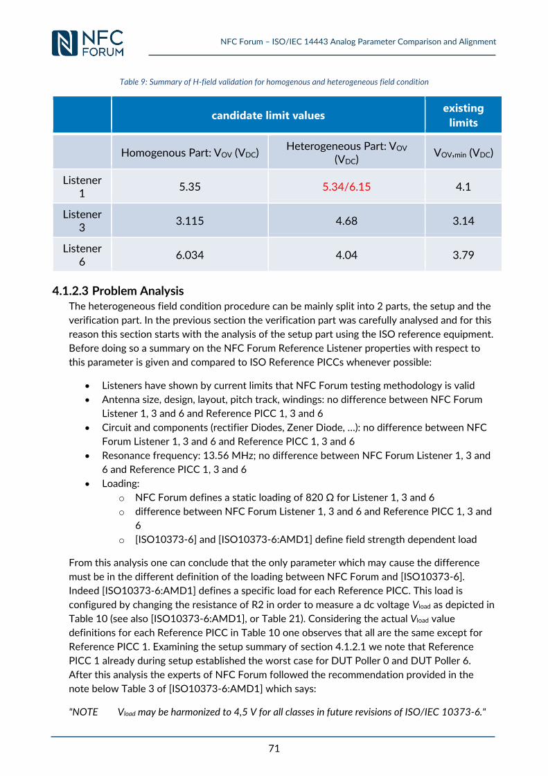
NFC Forum – ISO/IEC 14443 Analog Parameter Comparison and Alignment
71
Table 9: Summary of H-field validation for homogenous and heterogeneous field condition
candidate limit values existing
limits
Homogenous Part: VOV (VDC) Heterogeneous Part: VOV
(VDC) VOV,min (VDC)
Listener 1
5.35 5.34/6.15 4.1
Listener 3
3.115 4.68 3.14
Listener 6
6.034 4.04 3.79
4.1.2.3 Problem Analysis The heterogeneous field condition procedure can be mainly split into 2 parts, the setup and the
verification part. In the previous section the verification part was carefully analysed and for this
reason this section starts with the analysis of the setup part using the ISO reference equipment.
Before doing so a summary on the NFC Forum Reference Listener properties with respect to
this parameter is given and compared to ISO Reference PICCs whenever possible:
Listeners have shown by current limits that NFC Forum testing methodology is valid
Antenna size, design, layout, pitch track, windings: no difference between NFC Forum
Listener 1, 3 and 6 and Reference PICC 1, 3 and 6
Circuit and components (rectifier Diodes, Zener Diode, …): no difference between NFC
Forum Listener 1, 3 and 6 and Reference PICC 1, 3 and 6
Resonance frequency: 13.56 MHz; no difference between NFC Forum Listener 1, 3 and
6 and Reference PICC 1, 3 and 6
Loading:
o NFC Forum defines a static loading of 820 Ω for Listener 1, 3 and 6
o difference between NFC Forum Listener 1, 3 and 6 and Reference PICC 1, 3 and
6
o [ISO10373-6] and [ISO10373-6:AMD1] define field strength dependent load
From this analysis one can conclude that the only parameter which may cause the difference
must be in the different definition of the loading between NFC Forum and [ISO10373-6].
Indeed [ISO10373-6:AMD1] defines a specific load for each Reference PICC. This load is
configured by changing the resistance of R2 in order to measure a dc voltage Vload as depicted in
Table 10 (see also [ISO10373-6:AMD1], or Table 21). Considering the actual Vload value
definitions for each Reference PICC in Table 10 one observes that all are the same except for
Reference PICC 1. Examining the setup summary of section 4.1.2.1 we note that Reference
PICC 1 already during setup established the worst case for DUT Poller 0 and DUT Poller 6.
After this analysis the experts of NFC Forum followed the recommendation provided in the
note below Table 3 of [ISO10373-6:AMD1] which says:
"NOTE Vload may be harmonized to 4,5 V for all classes in future revisions of ISO/IEC 10373-6."
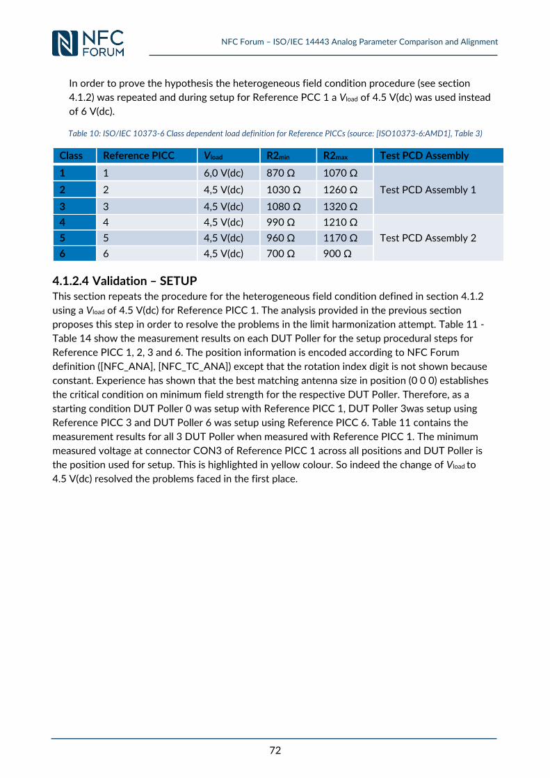
NFC Forum – ISO/IEC 14443 Analog Parameter Comparison and Alignment
72
In order to prove the hypothesis the heterogeneous field condition procedure (see section
4.1.2) was repeated and during setup for Reference PCC 1 a Vload of 4.5 V(dc) was used instead
of 6 V(dc).
Table 10: ISO/IEC 10373-6 Class dependent load definition for Reference PICCs (source: [ISO10373-6:AMD1], Table 3)
Class Reference PICC Vload R2min R2max Test PCD Assembly
1 1 6,0 V(dc) 870 Ω 1070 Ω
Test PCD Assembly 1 2 2 4,5 V(dc) 1030 Ω 1260 Ω
3 3 4,5 V(dc) 1080 Ω 1320 Ω
4 4 4,5 V(dc) 990 Ω 1210 Ω
Test PCD Assembly 2 5 5 4,5 V(dc) 960 Ω 1170 Ω
6 6 4,5 V(dc) 700 Ω 900 Ω
4.1.2.4 Validation – SETUP This section repeats the procedure for the heterogeneous field condition defined in section 4.1.2
using a Vload of 4.5 V(dc) for Reference PICC 1. The analysis provided in the previous section
proposes this step in order to resolve the problems in the limit harmonization attempt. Table 11 -
Table 14 show the measurement results on each DUT Poller for the setup procedural steps for
Reference PICC 1, 2, 3 and 6. The position information is encoded according to NFC Forum
definition ([NFC_ANA], [NFC_TC_ANA]) except that the rotation index digit is not shown because
constant. Experience has shown that the best matching antenna size in position (0 0 0) establishes
the critical condition on minimum field strength for the respective DUT Poller. Therefore, as a
starting condition DUT Poller 0 was setup with Reference PICC 1, DUT Poller 3was setup using
Reference PICC 3 and DUT Poller 6 was setup using Reference PICC 6. Table 11 contains the
measurement results for all 3 DUT Poller when measured with Reference PICC 1. The minimum
measured voltage at connector CON3 of Reference PICC 1 across all positions and DUT Poller is
the position used for setup. This is highlighted in yellow colour. So indeed the change of Vload to
4.5 V(dc) resolved the problems faced in the first place.
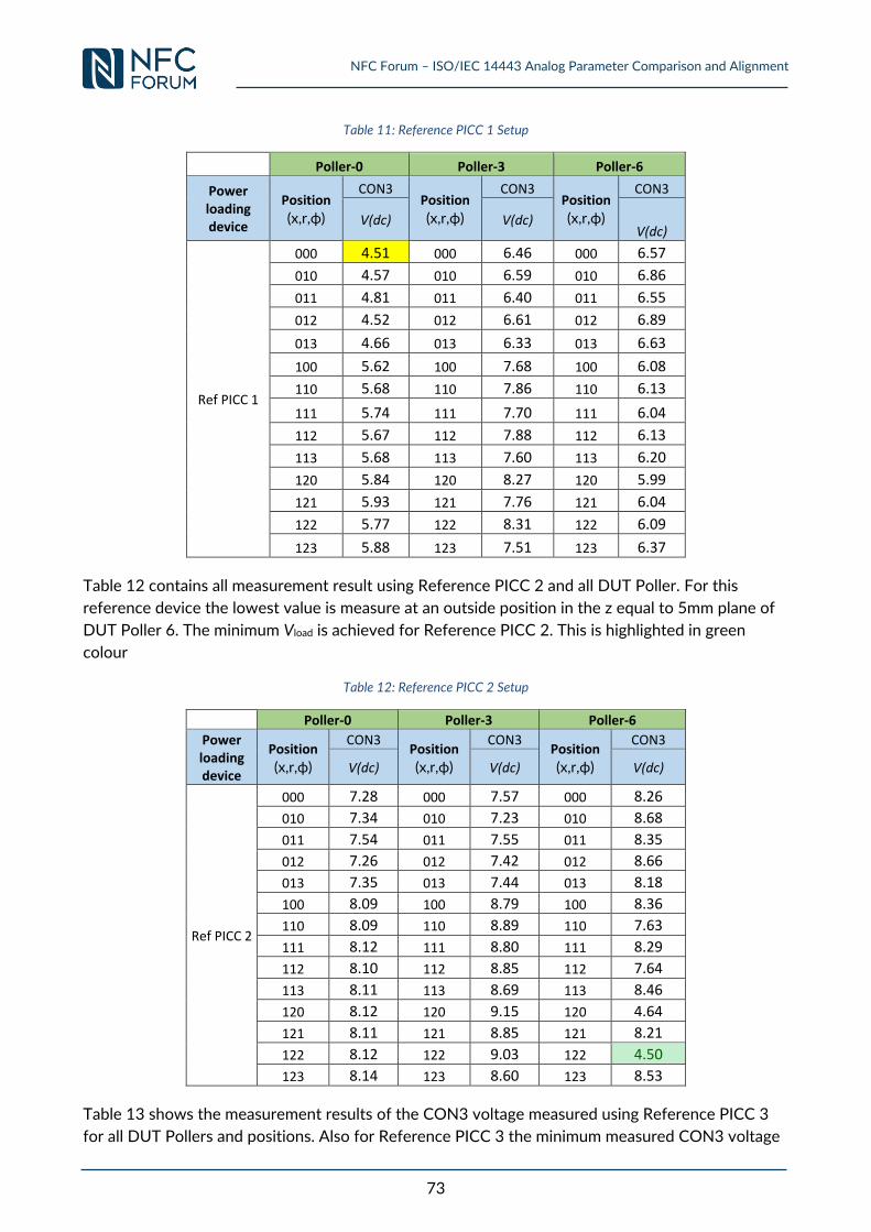
NFC Forum – ISO/IEC 14443 Analog Parameter Comparison and Alignment
73
Table 11: Reference PICC 1 Setup
Poller-0 Poller-3 Poller-6 Power loading device
Position
(x,r,ϕ) CON3
Position
(x,r,ϕ) CON3
Position
(x,r,ϕ) CON3
V(dc) V(dc) V(dc)
Ref PICC 1
000 4.51 000 6.46 000 6.57 010 4.57 010 6.59 010 6.86 011 4.81 011 6.40 011 6.55 012 4.52 012 6.61 012 6.89 013 4.66 013 6.33 013 6.63 100 5.62 100 7.68 100 6.08 110 5.68 110 7.86 110 6.13 111 5.74 111 7.70 111 6.04 112 5.67 112 7.88 112 6.13 113 5.68 113 7.60 113 6.20 120 5.84 120 8.27 120 5.99 121 5.93 121 7.76 121 6.04 122 5.77 122 8.31 122 6.09 123 5.88 123 7.51 123 6.37
Table 12 contains all measurement result using Reference PICC 2 and all DUT Poller. For this
reference device the lowest value is measure at an outside position in the z equal to 5mm plane of
DUT Poller 6. The minimum Vload is achieved for Reference PICC 2. This is highlighted in green
colour
Table 12: Reference PICC 2 Setup
Poller-0 Poller-3 Poller-6 Power loading device
Position
(x,r,ϕ) CON3
Position
(x,r,ϕ) CON3
Position
(x,r,ϕ) CON3
V(dc) V(dc) V(dc)
Ref PICC 2
000 7.28 000 7.57 000 8.26 010 7.34 010 7.23 010 8.68 011 7.54 011 7.55 011 8.35 012 7.26 012 7.42 012 8.66 013 7.35 013 7.44 013 8.18 100 8.09 100 8.79 100 8.36 110 8.09 110 8.89 110 7.63 111 8.12 111 8.80 111 8.29 112 8.10 112 8.85 112 7.64 113 8.11 113 8.69 113 8.46 120 8.12 120 9.15 120 4.64 121 8.11 121 8.85 121 8.21 122 8.12 122 9.03 122 4.50 123 8.14 123 8.60 123 8.53
Table 13 shows the measurement results of the CON3 voltage measured using Reference PICC 3
for all DUT Pollers and positions. Also for Reference PICC 3 the minimum measured CON3 voltage
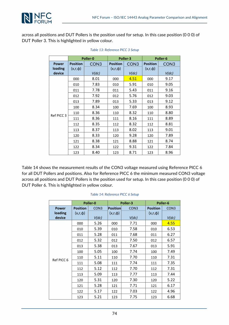
NFC Forum – ISO/IEC 14443 Analog Parameter Comparison and Alignment
74
across all positions and DUT Pollers is the position used for setup. In this case position (0 0 0) of
DUT Poller 3. This is highlighted in yellow colour.
Table 13: Reference PICC 3 Setup
Poller-0 Poller-3 Poller-6 Power loading device
Position
(x,r,ϕ) CON3 Position
(x,r,ϕ) CON3 Position
(x,r,ϕ) CON3
V(dc) V(dc) V(dc)
Ref PICC 3
000 8.01 000 4.51 000 9.17 010 7.83 010 5.91 010 9.05 011 7.78 011 5.43 011 9.16 012 7.92 012 5.76 012 9.03 013 7.89 013 5.33 013 9.12 100 8.34 100 7.69 100 8.93 110 8.36 110 8.32 110 8.80 111 8.36 111 8.16 111 8.89 112 8.35 112 8.32 112 8.81 113 8.37 113 8.02 113 9.01 120 8.33 120 9.28 120 7.89 121 8.38 121 8.88 121 8.74 122 8.34 122 9.31 122 7.84 123 8.40 123 8.71 123 8.96
Table 14 shows the measurement results of the CON3 voltage measured using Reference PICC 6
for all DUT Pollers and positions. Also for Reference PICC 6 the minimum measured CON3 voltage
across all positions and DUT Pollers is the position used for setup. In this case position (0 0 0) of
DUT Poller 6. This is highlighted in yellow colour.
Table 14: Reference PICC 6 Setup
Poller-0 Poller-3 Poller-6 Power loading device
Position
(x,r,ϕ) CON3 Position
(x,r,ϕ) CON3 Position
(x,r,ϕ) CON3
V(dc) V(dc) V(dc)
Ref PICC 6
000 5.26 000 7.71 000 4.55 010 5.39 010 7.58 010 6.53 011 5.28 011 7.68 011 6.27 012 5.32 012 7.50 012 6.57 013 5.38 013 7.67 013 5.91 100 5.05 100 7.74 100 7.49 110 5.11 110 7.70 110 7.31 111 5.08 111 7.74 111 7.35 112 5.12 112 7.70 112 7.31 113 5.09 113 7.77 113 7.44 120 5.31 120 7.30 120 5.22 121 5.28 121 7.71 121 6.17 122 5.17 122 7.03 122 4.96 123 5.21 123 7.75 123 6.68
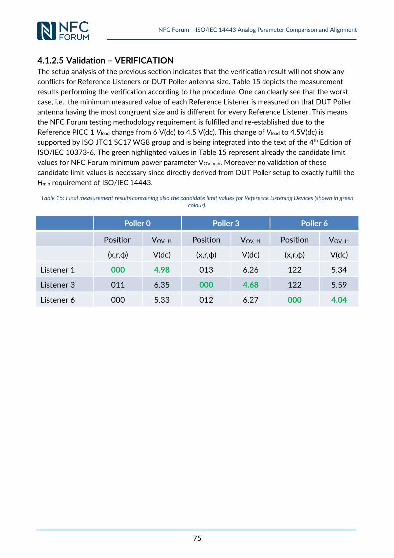
NFC Forum – ISO/IEC 14443 Analog Parameter Comparison and Alignment
75
4.1.2.5 Validation – VERIFICATION The setup analysis of the previous section indicates that the verification result will not show any
conflicts for Reference Listeners or DUT Poller antenna size. Table 15 depicts the measurement
results performing the verification according to the procedure. One can clearly see that the worst
case, i.e., the minimum measured value of each Reference Listener is measured on that DUT Poller
antenna having the most congruent size and is different for every Reference Listener. This means
the NFC Forum testing methodology requirement is fulfilled and re-established due to the
Reference PICC 1 Vload change from 6 V(dc) to 4.5 V(dc). This change of Vload to 4.5V(dc) is
supported by ISO JTC1 SC17 WG8 group and is being integrated into the text of the 4th Edition of
ISO/IEC 10373-6. The green highlighted values in Table 15 represent already the candidate limit
values for NFC Forum minimum power parameter VOV, min. Moreover no validation of these
candidate limit values is necessary since directly derived from DUT Poller setup to exactly fulfill the
Hmin requirement of ISO/IEC 14443.
Table 15: Final measurement results containing also the candidate limit values for Reference Listening Devices (shown in green colour).
Poller 0 Poller 3 Poller 6
Position VOV, J1 Position VOV, J1 Position VOV, J1
(x,r,ϕ) V(dc) (x,r,ϕ) V(dc) (x,r,ϕ) V(dc)
Listener 1 000 4.98 013 6.26 122 5.34
Listener 3 011 6.35 000 4.68 122 5.59
Listener 6 000 5.33 012 6.27 000 4.04
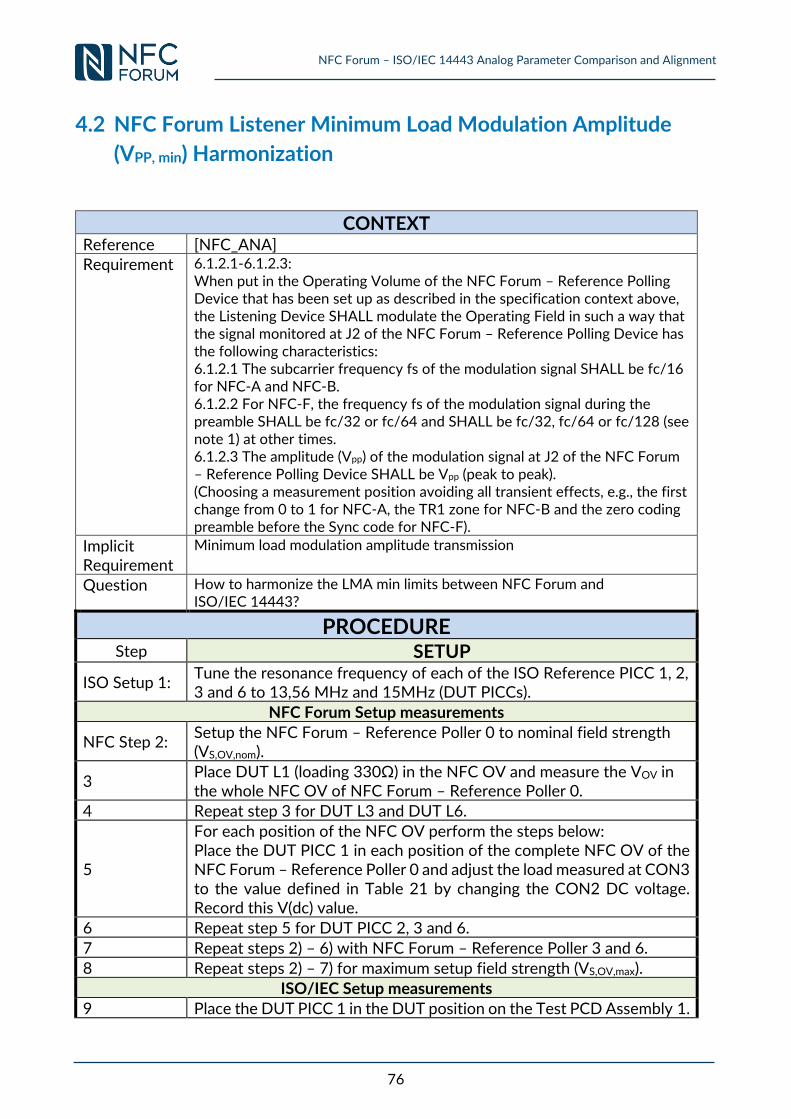
NFC Forum – ISO/IEC 14443 Analog Parameter Comparison and Alignment
76
4.2 NFC Forum Listener Minimum Load Modulation Amplitude
(VPP, min) Harmonization
CONTEXT
Reference [NFC_ANA] Requirement 6.1.2.1-6.1.2.3:
When put in the Operating Volume of the NFC Forum – Reference Polling Device that has been set up as described in the specification context above, the Listening Device SHALL modulate the Operating Field in such a way that the signal monitored at J2 of the NFC Forum – Reference Polling Device has the following characteristics: 6.1.2.1 The subcarrier frequency fs of the modulation signal SHALL be fc/16 for NFC-A and NFC-B. 6.1.2.2 For NFC-F, the frequency fs of the modulation signal during the preamble SHALL be fc/32 or fc/64 and SHALL be fc/32, fc/64 or fc/128 (see note 1) at other times. 6.1.2.3 The amplitude (Vpp) of the modulation signal at J2 of the NFC Forum – Reference Polling Device SHALL be Vpp (peak to peak). (Choosing a measurement position avoiding all transient effects, e.g., the first change from 0 to 1 for NFC-A, the TR1 zone for NFC-B and the zero coding preamble before the Sync code for NFC-F).
Implicit Requirement
Minimum load modulation amplitude transmission
Question How to harmonize the LMA min limits between NFC Forum and ISO/IEC 14443?
PROCEDURE Step SETUP
ISO Setup 1: Tune the resonance frequency of each of the ISO Reference PICC 1, 2, 3 and 6 to 13,56 MHz and 15MHz (DUT PICCs).
NFC Forum Setup measurements
NFC Step 2: Setup the NFC Forum – Reference Poller 0 to nominal field strength (VS,OV,nom).
3 Place DUT L1 (loading 330Ω) in the NFC OV and measure the VOV in the whole NFC OV of NFC Forum – Reference Poller 0.
4 Repeat step 3 for DUT L3 and DUT L6.
5
For each position of the NFC OV perform the steps below: Place the DUT PICC 1 in each position of the complete NFC OV of the NFC Forum – Reference Poller 0 and adjust the load measured at CON3 to the value defined in Table 21 by changing the CON2 DC voltage. Record this V(dc) value.
6 Repeat step 5 for DUT PICC 2, 3 and 6.
7 Repeat steps 2) – 6) with NFC Forum – Reference Poller 3 and 6.
8 Repeat steps 2) – 7) for maximum setup field strength (VS,OV,max).
ISO/IEC Setup measurements
9 Place the DUT PICC 1 in the DUT position on the Test PCD Assembly 1.
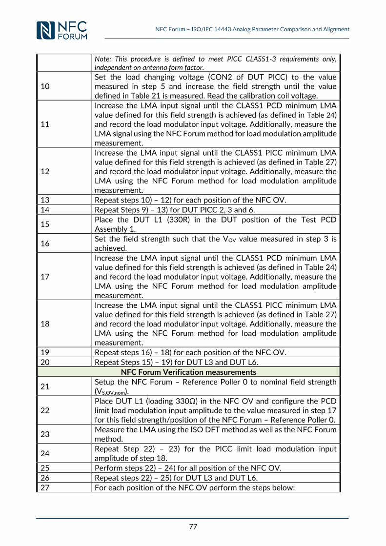
NFC Forum – ISO/IEC 14443 Analog Parameter Comparison and Alignment
77
Note: This procedure is defined to meet PICC CLASS1-3 requirements only, independent on antenna form factor.
10 Set the load changing voltage (CON2 of DUT PICC) to the value measured in step 5 and increase the field strength until the value defined in Table 21 is measured. Read the calibration coil voltage.
11
Increase the LMA input signal until the CLASS1 PCD minimum LMA value defined for this field strength is achieved (as defined in Table 24) and record the load modulator input voltage. Additionally, measure the LMA signal using the NFC Forum method for load modulation amplitude measurement.
12
Increase the LMA input signal until the CLASS1 PICC minimum LMA value defined for this field strength is achieved (as defined in Table 27) and record the load modulator input voltage. Additionally, measure the LMA using the NFC Forum method for load modulation amplitude measurement.
13 Repeat steps 10) – 12) for each position of the NFC OV.
14 Repeat Steps 9) – 13) for DUT PICC 2, 3 and 6.
15 Place the DUT L1 (330R) in the DUT position of the Test PCD Assembly 1.
16 Set the field strength such that the VOV value measured in step 3 is achieved.
17
Increase the LMA input signal until the CLASS1 PCD minimum LMA value defined for this field strength is achieved (as defined in Table 24) and record the load modulator input voltage. Additionally, measure the LMA using the NFC Forum method for load modulation amplitude measurement.
18
Increase the LMA input signal until the CLASS1 PICC minimum LMA value defined for this field strength is achieved (as defined in Table 27) and record the load modulator input voltage. Additionally, measure the LMA using the NFC Forum method for load modulation amplitude measurement.
19 Repeat steps 16) – 18) for each position of the NFC OV.
20 Repeat Steps 15) – 19) for DUT L3 and DUT L6.
NFC Forum Verification measurements
21 Setup the NFC Forum – Reference Poller 0 to nominal field strength (VS,OV,nom).
22 Place DUT L1 (loading 330Ω) in the NFC OV and configure the PCD limit load modulation input amplitude to the value measured in step 17 for this field strength/position of the NFC Forum – Reference Poller 0.
23 Measure the LMA using the ISO DFT method as well as the NFC Forum method.
24 Repeat Step 22) – 23) for the PICC limit load modulation input amplitude of step 18.
25 Perform steps 22) – 24) for all position of the NFC OV.
26 Repeat steps 22) – 25) for DUT L3 and DUT L6.
27 For each position of the NFC OV perform the steps below:
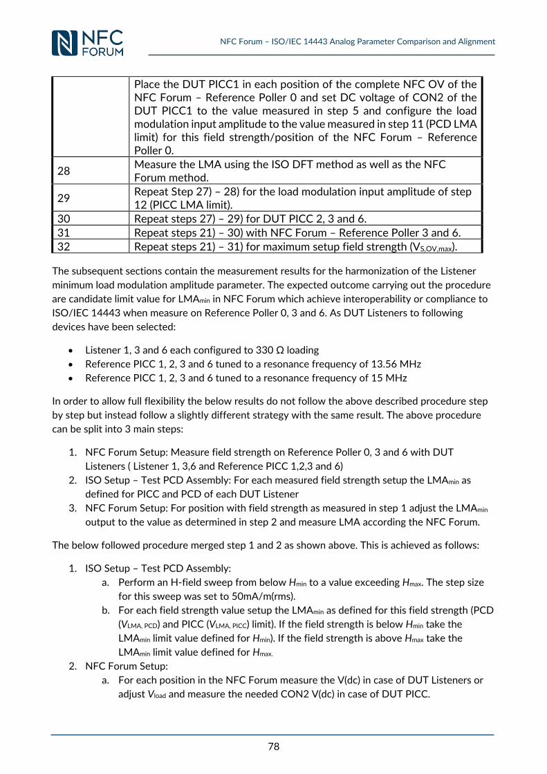
NFC Forum – ISO/IEC 14443 Analog Parameter Comparison and Alignment
78
Place the DUT PICC1 in each position of the complete NFC OV of the NFC Forum – Reference Poller 0 and set DC voltage of CON2 of the DUT PICC1 to the value measured in step 5 and configure the load modulation input amplitude to the value measured in step 11 (PCD LMA limit) for this field strength/position of the NFC Forum – Reference Poller 0.
28 Measure the LMA using the ISO DFT method as well as the NFC Forum method.
29 Repeat Step 27) – 28) for the load modulation input amplitude of step 12 (PICC LMA limit).
30 Repeat steps 27) – 29) for DUT PICC 2, 3 and 6.
31 Repeat steps 21) – 30) with NFC Forum – Reference Poller 3 and 6.
32 Repeat steps 21) – 31) for maximum setup field strength (VS,OV,max).
The subsequent sections contain the measurement results for the harmonization of the Listener
minimum load modulation amplitude parameter. The expected outcome carrying out the procedure
are candidate limit value for LMAmin in NFC Forum which achieve interoperability or compliance to
ISO/IEC 14443 when measure on Reference Poller 0, 3 and 6. As DUT Listeners to following
devices have been selected:
Listener 1, 3 and 6 each configured to 330 Ω loading
Reference PICC 1, 2, 3 and 6 tuned to a resonance frequency of 13.56 MHz
Reference PICC 1, 2, 3 and 6 tuned to a resonance frequency of 15 MHz
In order to allow full flexibility the below results do not follow the above described procedure step
by step but instead follow a slightly different strategy with the same result. The above procedure
can be split into 3 main steps:
1. NFC Forum Setup: Measure field strength on Reference Poller 0, 3 and 6 with DUT
Listeners ( Listener 1, 3,6 and Reference PICC 1,2,3 and 6)
2. ISO Setup – Test PCD Assembly: For each measured field strength setup the LMAmin as
defined for PICC and PCD of each DUT Listener
3. NFC Forum Setup: For position with field strength as measured in step 1 adjust the LMAmin
output to the value as determined in step 2 and measure LMA according the NFC Forum.
The below followed procedure merged step 1 and 2 as shown above. This is achieved as follows:
1. ISO Setup – Test PCD Assembly:
a. Perform an H-field sweep from below Hmin to a value exceeding Hmax. The step size
for this sweep was set to 50mA/m(rms).
b. For each field strength value setup the LMAmin as defined for this field strength (PCD
(VLMA, PCD) and PICC (VLMA, PICC) limit). If the field strength is below Hmin take the
LMAmin limit value defined for Hmin). If the field strength is above Hmax take the
LMAmin limit value defined for Hmax.
2. NFC Forum Setup:
a. For each position in the NFC Forum measure the V(dc) in case of DUT Listeners or
adjust Vload and measure the needed CON2 V(dc) in case of DUT PICC.
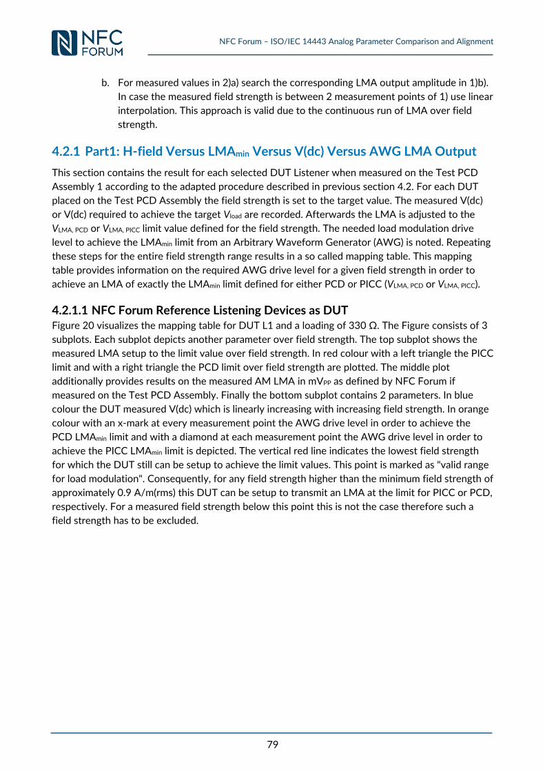
NFC Forum – ISO/IEC 14443 Analog Parameter Comparison and Alignment
79
b. For measured values in 2)a) search the corresponding LMA output amplitude in 1)b).
In case the measured field strength is between 2 measurement points of 1) use linear
interpolation. This approach is valid due to the continuous run of LMA over field
strength.
4.2.1 Part1: H-field Versus LMAmin Versus V(dc) Versus AWG LMA Output
This section contains the result for each selected DUT Listener when measured on the Test PCD
Assembly 1 according to the adapted procedure described in previous section 4.2. For each DUT
placed on the Test PCD Assembly the field strength is set to the target value. The measured V(dc)
or V(dc) required to achieve the target Vload are recorded. Afterwards the LMA is adjusted to the
VLMA, PCD or VLMA, PICC limit value defined for the field strength. The needed load modulation drive
level to achieve the LMAmin limit from an Arbitrary Waveform Generator (AWG) is noted. Repeating
these steps for the entire field strength range results in a so called mapping table. This mapping
table provides information on the required AWG drive level for a given field strength in order to
achieve an LMA of exactly the LMAmin limit defined for either PCD or PICC (VLMA, PCD or VLMA, PICC).
4.2.1.1 NFC Forum Reference Listening Devices as DUT Figure 20 visualizes the mapping table for DUT L1 and a loading of 330 Ω. The Figure consists of 3
subplots. Each subplot depicts another parameter over field strength. The top subplot shows the
measured LMA setup to the limit value over field strength. In red colour with a left triangle the PICC
limit and with a right triangle the PCD limit over field strength are plotted. The middle plot
additionally provides results on the measured AM LMA in mVPP as defined by NFC Forum if
measured on the Test PCD Assembly. Finally the bottom subplot contains 2 parameters. In blue
colour the DUT measured V(dc) which is linearly increasing with increasing field strength. In orange
colour with an x-mark at every measurement point the AWG drive level in order to achieve the
PCD LMAmin limit and with a diamond at each measurement point the AWG drive level in order to
achieve the PICC LMAmin limit is depicted. The vertical red line indicates the lowest field strength
for which the DUT still can be setup to achieve the limit values. This point is marked as "valid range
for load modulation". Consequently, for any field strength higher than the minimum field strength of
approximately 0.9 A/m(rms) this DUT can be setup to transmit an LMA at the limit for PICC or PCD,
respectively. For a measured field strength below this point this is not the case therefore such a
field strength has to be excluded.
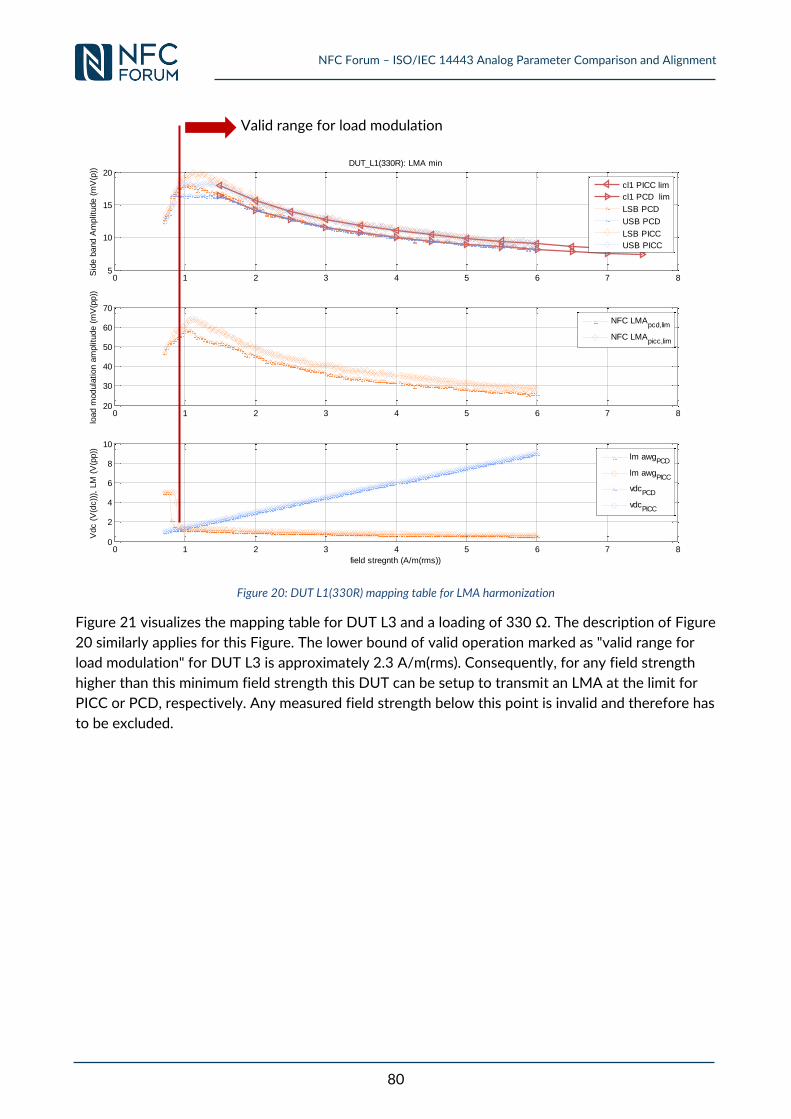
NFC Forum – ISO/IEC 14443 Analog Parameter Comparison and Alignment
80
Figure 20: DUT L1(330R) mapping table for LMA harmonization
Figure 21 visualizes the mapping table for DUT L3 and a loading of 330 Ω. The description of Figure
20 similarly applies for this Figure. The lower bound of valid operation marked as "valid range for
load modulation" for DUT L3 is approximately 2.3 A/m(rms). Consequently, for any field strength
higher than this minimum field strength this DUT can be setup to transmit an LMA at the limit for
PICC or PCD, respectively. Any measured field strength below this point is invalid and therefore has
to be excluded.
0 1 2 3 4 5 6 7 85
10
15
20
Sid
e b
and A
mplit
ude (
mV
(p))
DUT_L1(330R): LMA min
cl1 PICC lim
cl1 PCD lim
LSB PCD
USB PCD
LSB PICC
USB PICC
0 1 2 3 4 5 6 7 820
30
40
50
60
70
load m
odula
tion a
mplit
ude (
mV
(pp))
NFC LMApcd,lim
NFC LMApicc,lim
0 1 2 3 4 5 6 7 80
2
4
6
8
10
Vdc (
V(d
c))
), L
M (
V(p
p))
field stregnth (A/m(rms))
lm awgPCD
lm awgPICC
vdcPCD
vdcPICC
Valid range for load modulation
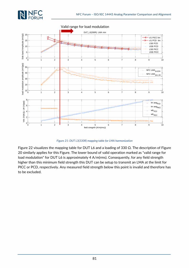
NFC Forum – ISO/IEC 14443 Analog Parameter Comparison and Alignment
81
Figure 21: DUT L3(330R) mapping table for LMA harmonization
Figure 22 visualizes the mapping table for DUT L6 and a loading of 330 Ω. The description of Figure
20 similarly applies for this Figure. The lower bound of valid operation marked as "valid range for
load modulation" for DUT L6 is approximately 4 A/m(rms). Consequently, for any field strength
higher than this minimum field strength this DUT can be setup to transmit an LMA at the limit for
PICC or PCD, respectively. Any measured field strength below this point is invalid and therefore has
to be excluded.
0 1 2 3 4 5 6 7 8 9 100
5
10
15
20
Sid
e b
and A
mplit
ude (
mV
(p))
DUT_L3(330R): LMA min
cl1 PICC lim
cl1 PCD lim
LSB PCD
USB PCD
LSB PICC
USB PICC
0 1 2 3 4 5 6 7 8 9 1010
20
30
40
50
load m
odula
tion a
mplit
ude (
mV
(pp))
NFC LMApcd,lim
NFC LMApicc,lim
0 1 2 3 4 5 6 7 8 9 100
2
4
6
8
Vdc (
V(d
c))
), L
M (
V(p
p))
field stregnth (A/m(rms))
lm awgPCD
lm awgPICC
vdcPCD
vdcPICC
Valid range for load modulation
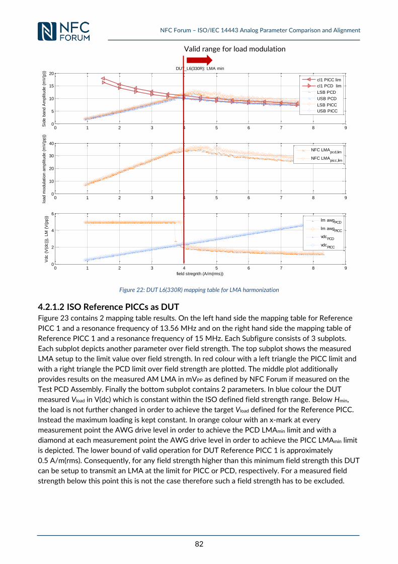
NFC Forum – ISO/IEC 14443 Analog Parameter Comparison and Alignment
82
Figure 22: DUT L6(330R) mapping table for LMA harmonization
4.2.1.2 ISO Reference PICCs as DUT Figure 23 contains 2 mapping table results. On the left hand side the mapping table for Reference
PICC 1 and a resonance frequency of 13.56 MHz and on the right hand side the mapping table of
Reference PICC 1 and a resonance frequency of 15 MHz. Each Subfigure consists of 3 subplots.
Each subplot depicts another parameter over field strength. The top subplot shows the measured
LMA setup to the limit value over field strength. In red colour with a left triangle the PICC limit and
with a right triangle the PCD limit over field strength are plotted. The middle plot additionally
provides results on the measured AM LMA in mVPP as defined by NFC Forum if measured on the
Test PCD Assembly. Finally the bottom subplot contains 2 parameters. In blue colour the DUT
measured Vload in V(dc) which is constant within the ISO defined field strength range. Below Hmin,
the load is not further changed in order to achieve the target Vload defined for the Reference PICC.
Instead the maximum loading is kept constant. In orange colour with an x-mark at every
measurement point the AWG drive level in order to achieve the PCD LMAmin limit and with a
diamond at each measurement point the AWG drive level in order to achieve the PICC LMAmin limit
is depicted. The lower bound of valid operation for DUT Reference PICC 1 is approximately
0.5 A/m(rms). Consequently, for any field strength higher than this minimum field strength this DUT
can be setup to transmit an LMA at the limit for PICC or PCD, respectively. For a measured field
strength below this point this is not the case therefore such a field strength has to be excluded.
0 1 2 3 4 5 6 7 8 90
5
10
15
20
Sid
e b
and A
mplit
ude (
mV
(p))
DUT_L6(330R): LMA min
cl1 PICC lim
cl1 PCD lim
LSB PCD
USB PCD
LSB PICC
USB PICC
0 1 2 3 4 5 6 7 8 90
10
20
30
40
load m
odula
tion a
mplit
ude (
mV
(pp))
NFC LMApcd,lim
NFC LMApicc,lim
0 1 2 3 4 5 6 7 8 90
2
4
6
Vdc (
V(d
c))
), L
M (
V(p
p))
field stregnth (A/m(rms))
lm awgPCD
lm awgPICC
vdcPCD
vdcPICC
Valid range for load modulation
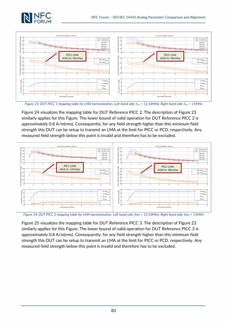
NFC Forum – ISO/IEC 14443 Analog Parameter Comparison and Alignment
83
Figure 23: DUT PICC 1 mapping table for LMA harmonization. Left hand side: fres = 13,56MHz; Right hand side: fres = 15MHz
Figure 24 visualizes the mapping table for DUT Reference PICC 2. The description of Figure 23
similarly applies for this Figure. The lower bound of valid operation for DUT Reference PICC 2 is
approximately 0.8 A/m(rms). Consequently, for any field strength higher than this minimum field
strength this DUT can be setup to transmit an LMA at the limit for PICC or PCD, respectively. Any
measured field strength below this point is invalid and therefore has to be excluded.
Figure 24: DUT PICC 2 mapping table for LMA harmonization. Left hand side: fres = 13,56MHz; Right hand side: fres = 15MHz
Figure 25 visualizes the mapping table for DUT Reference PICC 3. The description of Figure 23
similarly applies for this Figure. The lower bound of valid operation for DUT Reference PICC 3 is
approximately 0.8 A/m(rms). Consequently, for any field strength higher than this minimum field
strength this DUT can be setup to transmit an LMA at the limit for PICC or PCD, respectively. Any
measured field strength below this point is invalid and therefore has to be excluded.
0 1 2 3 4 5 6 7 85
10
15
20
25
Sid
e b
and A
mplit
ude (
mV
(p))
DUT_PICC1(13_56MHz): LMA min
cl1 PICC lim
cl1 PCD lim
LSB PCD
USB PCD
LSB PICC
USB PICC
0 1 2 3 4 5 6 7 820
30
40
50
60
load m
odula
tion a
mplit
ude (
mV
(pp))
NFC LMApcd,lim
NFC LMApicc,lim
0 1 2 3 4 5 6 7 80
2
4
6
8
Vdc (
V(d
c))
), L
M (
V(p
p))
field stregnth (A/m(rms))
lm awgPCD
lm awgPICC
vdcPCD
vdcPICC
0 1 2 3 4 5 6 7 85
10
15
20
25
Sid
e b
and A
mplit
ude (
mV
(p))
DUT_PICC1(15MHz): LMA min
cl1 PICC lim
cl1 PCD lim
LSB PCD
USB PCD
LSB PICC
USB PICC
0 1 2 3 4 5 6 7 820
30
40
50
load m
odula
tion a
mplit
ude (
mV
(pp))
NFC LMApcd,lim
NFC LMApicc,lim
0 1 2 3 4 5 6 7 80
2
4
6
8
Vdc (
V(d
c))
), L
M (
V(p
p))
field stregnth (A/m(rms))
lm awgPCD
lm awgPICC
vdcPCD
vdcPICC
0 1 2 3 4 5 6 7 8 90
5
10
15
20
25
Sid
e b
and A
mplit
ude (
mV
(p))
DUT_PICC2(13_56MHz): LMA min
cl1 PICC lim
cl1 PCD lim
LSB PCD
USB PCD
LSB PICC
USB PICC
0 1 2 3 4 5 6 7 8 90
20
40
60
80
load m
odula
tion a
mplit
ude (
mV
(pp))
NFC LMApcd,lim
NFC LMApicc,lim
0 1 2 3 4 5 6 7 8 91
2
3
4
5
Vdc (
V(d
c))
), L
M (
V(p
p))
field stregnth (A/m(rms))
lm awgPCD
lm awgPICC
vdcPCD
vdcPICC
0 1 2 3 4 5 6 7 8 95
10
15
20
25
Sid
e b
and A
mplit
ude (
mV
(p))
DUT_PICC2(15MHz): LMA min
cl1 PICC lim
cl1 PCD lim
LSB PCD
USB PCD
LSB PICC
USB PICC
0 1 2 3 4 5 6 7 8 920
30
40
50
60
70
load m
odula
tion a
mplit
ude (
mV
(pp))
NFC LMApcd,lim
NFC LMApicc,lim
0 1 2 3 4 5 6 7 8 91
2
3
4
5
Vdc (
V(d
c))
), L
M (
V(p
p))
field stregnth (A/m(rms))
lm awgPCD
lm awgPICC
vdcPCD
vdcPICC
PICC LMA @2A/m: 46mVpp
PICC LMA @2A/m: 40mVpp
PICC LMA @2A/m: 54mVpp
PICC LMA @2A/m: 48mVpp
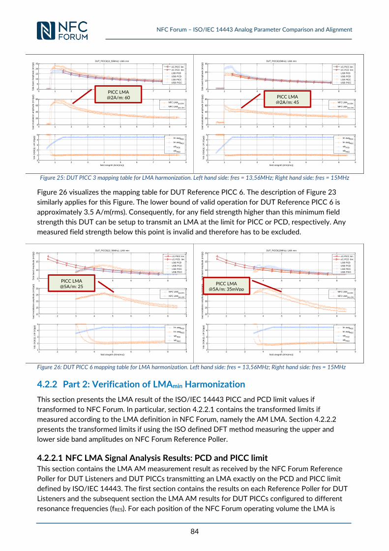
NFC Forum – ISO/IEC 14443 Analog Parameter Comparison and Alignment
84
Figure 25: DUT PICC 3 mapping table for LMA harmonization. Left hand side: fres = 13,56MHz; Right hand side: fres = 15MHz
Figure 26 visualizes the mapping table for DUT Reference PICC 6. The description of Figure 23
similarly applies for this Figure. The lower bound of valid operation for DUT Reference PICC 6 is
approximately 3.5 A/m(rms). Consequently, for any field strength higher than this minimum field
strength this DUT can be setup to transmit an LMA at the limit for PICC or PCD, respectively. Any
measured field strength below this point is invalid and therefore has to be excluded.
Figure 26: DUT PICC 6 mapping table for LMA harmonization. Left hand side: fres = 13,56MHz; Right hand side: fres = 15MHz
4.2.2 Part 2: Verification of LMAmin Harmonization
This section presents the LMA result of the ISO/IEC 14443 PICC and PCD limit values if
transformed to NFC Forum. In particular, section 4.2.2.1 contains the transformed limits if
measured according to the LMA definition in NFC Forum, namely the AM LMA. Section 4.2.2.2
presents the transformed limits if using the ISO defined DFT method measuring the upper and
lower side band amplitudes on NFC Forum Reference Poller.
4.2.2.1 NFC LMA Signal Analysis Results: PCD and PICC limit This section contains the LMA AM measurement result as received by the NFC Forum Reference
Poller for DUT Listeners and DUT PICCs transmitting an LMA exactly on the PCD and PICC limit
defined by ISO/IEC 14443. The first section contains the results on each Reference Poller for DUT
Listeners and the subsequent section the LMA AM results for DUT PICCs configured to different
resonance frequencies (fRES). For each position of the NFC Forum operating volume the LMA is
0 1 2 3 4 5 6 7 8 90
5
10
15
20
25
Sid
e b
and A
mplit
ude (
mV
(p))
DUT_PICC3(13_56MHz): LMA min
cl1 PICC lim
cl1 PCD lim
LSB PCD
USB PCD
LSB PICC
USB PICC
0 1 2 3 4 5 6 7 8 90
20
40
60
80
load m
odula
tion a
mplit
ude (
mV
(pp))
NFC LMApcd,lim
NFC LMApicc,lim
0 1 2 3 4 5 6 7 8 90
1
2
3
4
5
Vdc (
V(d
c))
), L
M (
V(p
p))
field stregnth (A/m(rms))
lm awgPCD
lm awgPICC
vdcPCD
vdcPICC
0 1 2 3 4 5 6 7 8 90
10
20
30
Sid
e b
and A
mplit
ude (
mV
(p))
DUT_PICC3(15MHz): LMA min
cl1 PICC lim
cl1 PCD lim
LSB PCD
USB PCD
LSB PICC
USB PICC
0 1 2 3 4 5 6 7 8 90
20
40
60
80
load m
odula
tion a
mplit
ude (
mV
(pp))
NFC LMApcd,lim
NFC LMApicc,lim
0 1 2 3 4 5 6 7 8 90
1
2
3
4
5
Vdc (
V(d
c))
), L
M (
V(p
p))
field stregnth (A/m(rms))
lm awgPCD
lm awgPICC
vdcPCD
vdcPICC
1 2 3 4 5 6 7 8 95
10
15
20
Sid
e b
and A
mplit
ude (
mV
(p))
DUT_PICC6(13_56MHz): LMA min
cl1 PICC lim
cl1 PCD lim
LSB PCD
USB PCD
LSB PICC
USB PICC
1 2 3 4 5 6 7 8 910
15
20
25
30
load m
odula
tion a
mplit
ude (
mV
(pp))
NFC LMApcd,lim
NFC LMApicc,lim
1 2 3 4 5 6 7 8 91
2
3
4
5
Vdc (
V(d
c))
), L
M (
V(p
p))
field stregnth (A/m(rms))
lm awgPCD
lm awgPICC
vdcPCD
vdcPICC
1 2 3 4 5 6 7 8 95
10
15
20
Sid
e b
and A
mplit
ude (
mV
(p))
DUT_PICC6(15MHz): LMA min
cl1 PICC lim
cl1 PCD lim
LSB PCD
USB PCD
LSB PICC
USB PICC
1 2 3 4 5 6 7 8 920
25
30
35
40
load m
odula
tion a
mplit
ude (
mV
(pp))
NFC LMApcd,lim
NFC LMApicc,lim
1 2 3 4 5 6 7 8 91
2
3
4
5
Vdc (
V(d
c))
), L
M (
V(p
p))
field stregnth (A/m(rms))
lm awgPCD
lm awgPICC
vdcPCD
vdcPICC
PICC LMA @2A/m: 60
mVpp PICC LMA @2A/m: 45
mVpp
PICC LMA @5A/m: 25
mVpp
PICC LMA @5A/m: 35mVpp
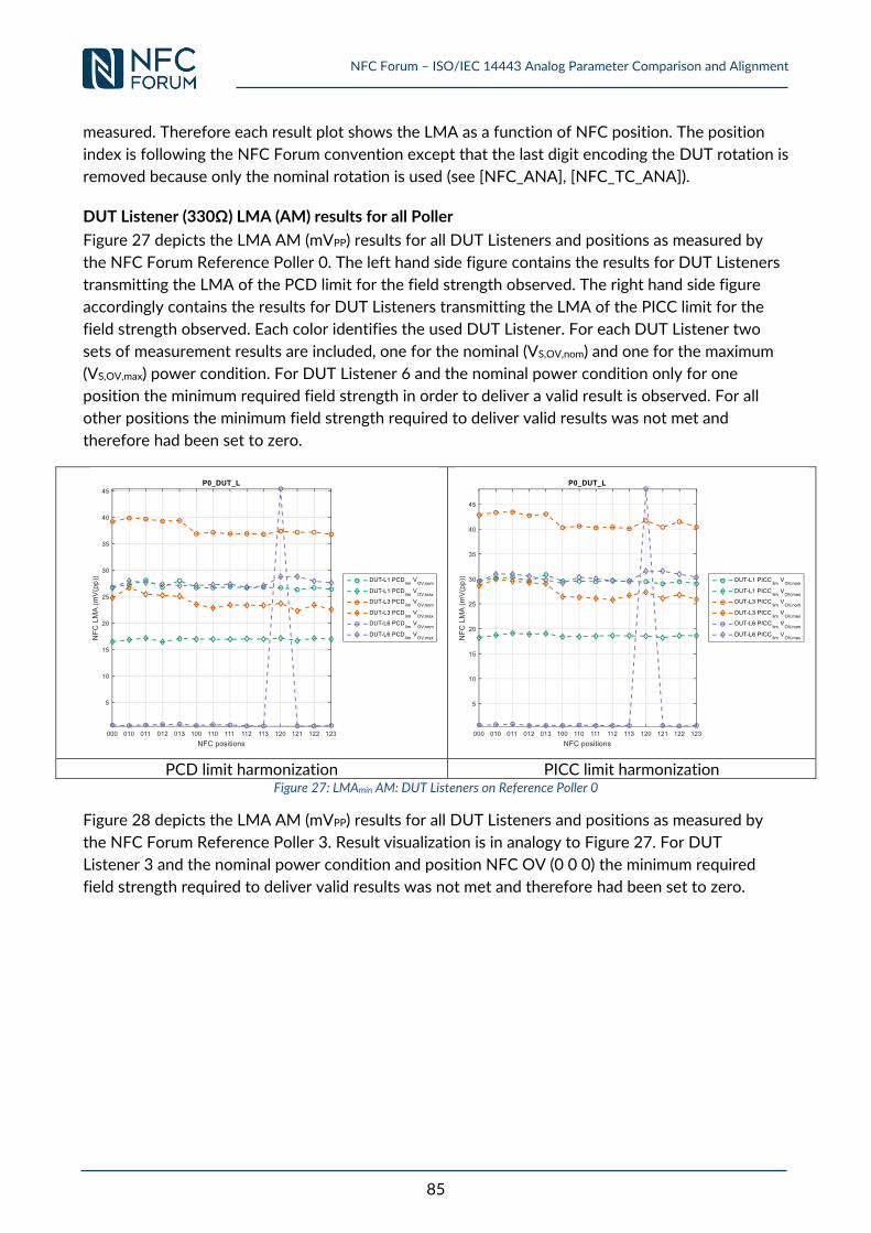
NFC Forum – ISO/IEC 14443 Analog Parameter Comparison and Alignment
85
measured. Therefore each result plot shows the LMA as a function of NFC position. The position
index is following the NFC Forum convention except that the last digit encoding the DUT rotation is
removed because only the nominal rotation is used (see [NFC_ANA], [NFC_TC_ANA]).
DUT Listener (330Ω) LMA (AM) results for all Poller
Figure 27 depicts the LMA AM (mVPP) results for all DUT Listeners and positions as measured by
the NFC Forum Reference Poller 0. The left hand side figure contains the results for DUT Listeners
transmitting the LMA of the PCD limit for the field strength observed. The right hand side figure
accordingly contains the results for DUT Listeners transmitting the LMA of the PICC limit for the
field strength observed. Each color identifies the used DUT Listener. For each DUT Listener two
sets of measurement results are included, one for the nominal (VS,OV,nom) and one for the maximum
(VS,OV,max) power condition. For DUT Listener 6 and the nominal power condition only for one
position the minimum required field strength in order to deliver a valid result is observed. For all
other positions the minimum field strength required to deliver valid results was not met and
therefore had been set to zero.
PCD limit harmonization PICC limit harmonization
Figure 27: LMAmin AM: DUT Listeners on Reference Poller 0
Figure 28 depicts the LMA AM (mVPP) results for all DUT Listeners and positions as measured by
the NFC Forum Reference Poller 3. Result visualization is in analogy to Figure 27. For DUT
Listener 3 and the nominal power condition and position NFC OV (0 0 0) the minimum required
field strength required to deliver valid results was not met and therefore had been set to zero.
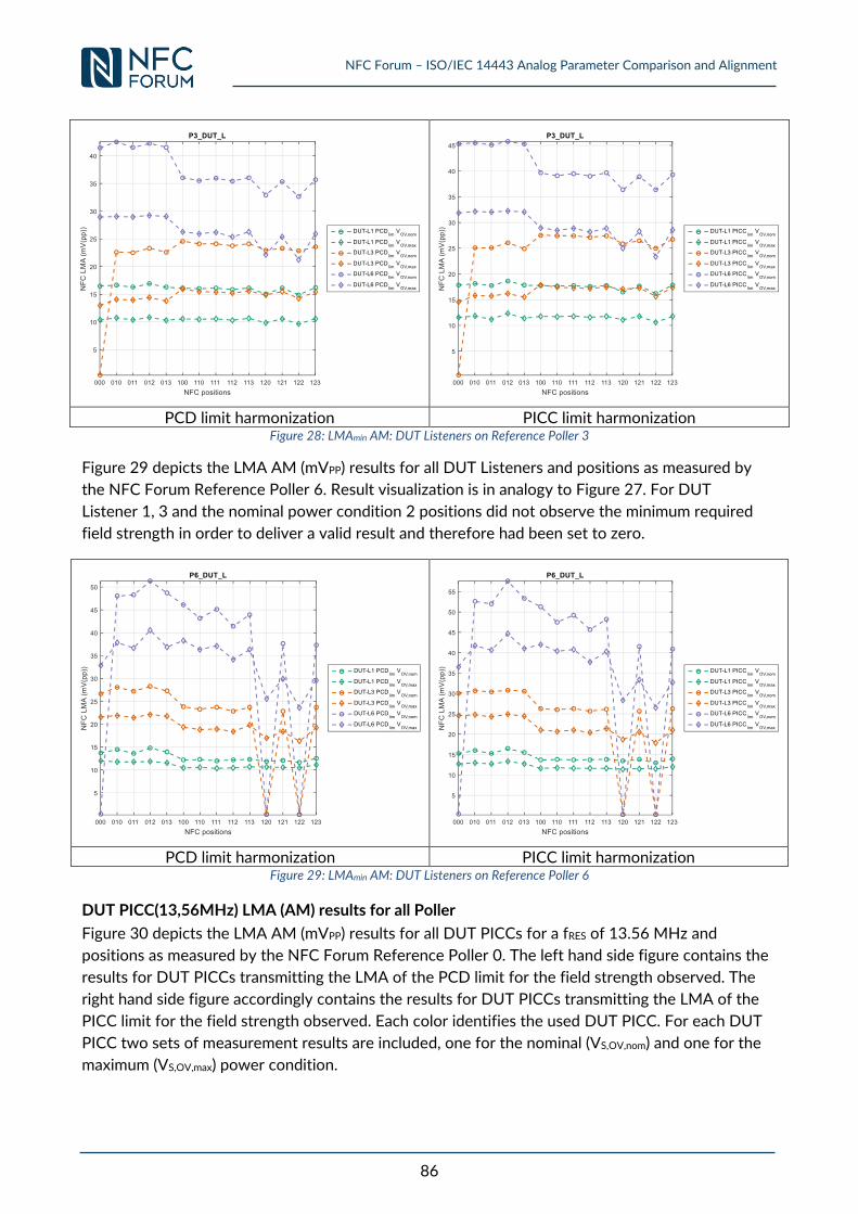
NFC Forum – ISO/IEC 14443 Analog Parameter Comparison and Alignment
86
PCD limit harmonization PICC limit harmonization
Figure 28: LMAmin AM: DUT Listeners on Reference Poller 3
Figure 29 depicts the LMA AM (mVPP) results for all DUT Listeners and positions as measured by
the NFC Forum Reference Poller 6. Result visualization is in analogy to Figure 27. For DUT
Listener 1, 3 and the nominal power condition 2 positions did not observe the minimum required
field strength in order to deliver a valid result and therefore had been set to zero.
PCD limit harmonization PICC limit harmonization
Figure 29: LMAmin AM: DUT Listeners on Reference Poller 6
DUT PICC(13,56MHz) LMA (AM) results for all Poller
Figure 30 depicts the LMA AM (mVPP) results for all DUT PICCs for a fRES of 13.56 MHz and
positions as measured by the NFC Forum Reference Poller 0. The left hand side figure contains the
results for DUT PICCs transmitting the LMA of the PCD limit for the field strength observed. The
right hand side figure accordingly contains the results for DUT PICCs transmitting the LMA of the
PICC limit for the field strength observed. Each color identifies the used DUT PICC. For each DUT
PICC two sets of measurement results are included, one for the nominal (VS,OV,nom) and one for the
maximum (VS,OV,max) power condition.
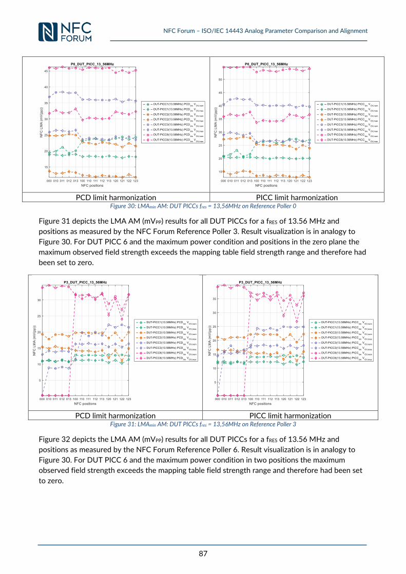
NFC Forum – ISO/IEC 14443 Analog Parameter Comparison and Alignment
87
PCD limit harmonization PICC limit harmonization
Figure 30: LMAmin AM: DUT PICCs fres = 13,56MHz on Reference Poller 0
Figure 31 depicts the LMA AM (mVPP) results for all DUT PICCs for a fRES of 13.56 MHz and
positions as measured by the NFC Forum Reference Poller 3. Result visualization is in analogy to
Figure 30. For DUT PICC 6 and the maximum power condition and positions in the zero plane the
maximum observed field strength exceeds the mapping table field strength range and therefore had
been set to zero.
PCD limit harmonization PICC limit harmonization
Figure 31: LMAmin AM: DUT PICCs fres = 13,56MHz on Reference Poller 3
Figure 32 depicts the LMA AM (mVPP) results for all DUT PICCs for a fRES of 13.56 MHz and
positions as measured by the NFC Forum Reference Poller 6. Result visualization is in analogy to
Figure 30. For DUT PICC 6 and the maximum power condition in two positions the maximum
observed field strength exceeds the mapping table field strength range and therefore had been set
to zero.
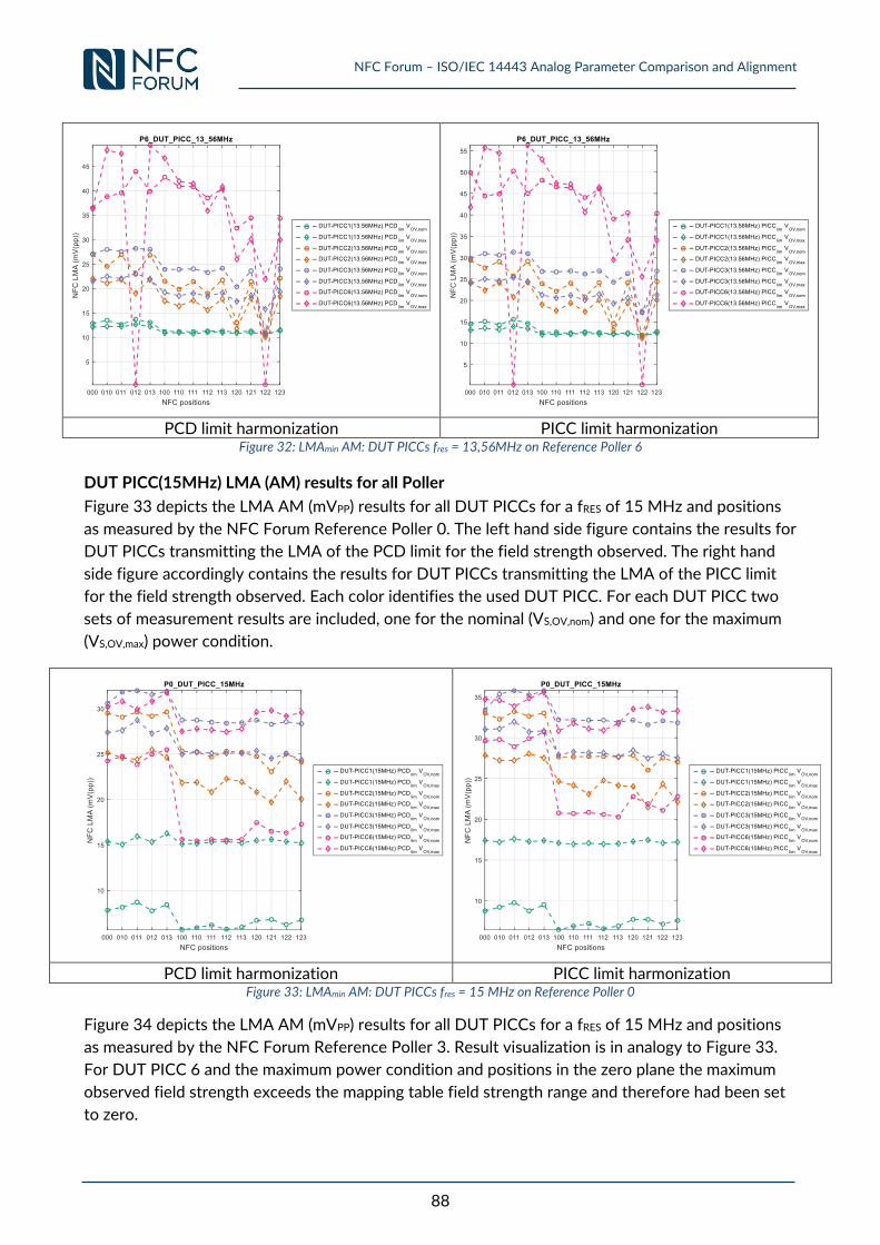
NFC Forum – ISO/IEC 14443 Analog Parameter Comparison and Alignment
88
PCD limit harmonization PICC limit harmonization
Figure 32: LMAmin AM: DUT PICCs fres = 13,56MHz on Reference Poller 6
DUT PICC(15MHz) LMA (AM) results for all Poller
Figure 33 depicts the LMA AM (mVPP) results for all DUT PICCs for a fRES of 15 MHz and positions
as measured by the NFC Forum Reference Poller 0. The left hand side figure contains the results for
DUT PICCs transmitting the LMA of the PCD limit for the field strength observed. The right hand
side figure accordingly contains the results for DUT PICCs transmitting the LMA of the PICC limit
for the field strength observed. Each color identifies the used DUT PICC. For each DUT PICC two
sets of measurement results are included, one for the nominal (VS,OV,nom) and one for the maximum
(VS,OV,max) power condition.
PCD limit harmonization PICC limit harmonization
Figure 33: LMAmin AM: DUT PICCs fres = 15 MHz on Reference Poller 0
Figure 34 depicts the LMA AM (mVPP) results for all DUT PICCs for a fRES of 15 MHz and positions
as measured by the NFC Forum Reference Poller 3. Result visualization is in analogy to Figure 33.
For DUT PICC 6 and the maximum power condition and positions in the zero plane the maximum
observed field strength exceeds the mapping table field strength range and therefore had been set
to zero.
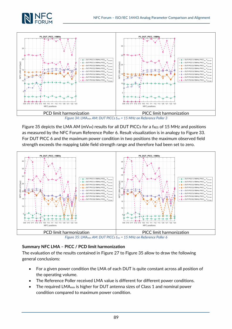
NFC Forum – ISO/IEC 14443 Analog Parameter Comparison and Alignment
89
PCD limit harmonization PICC limit harmonization
Figure 34: LMAmin AM: DUT PICCs fres = 15 MHz on Reference Poller 3
Figure 35 depicts the LMA AM (mVPP) results for all DUT PICCs for a fRES of 15 MHz and positions
as measured by the NFC Forum Reference Poller 6. Result visualization is in analogy to Figure 33.
For DUT PICC 6 and the maximum power condition in two positions the maximum observed field
strength exceeds the mapping table field strength range and therefore had been set to zero.
PCD limit harmonization PICC limit harmonization
Figure 35: LMAmin AM: DUT PICCs fres = 15 MHz on Reference Poller 6
Summary NFC LMA – PICC / PCD limit harmonization
The evaluation of the results contained in Figure 27 to Figure 35 allow to draw the following
general conclusions:
For a given power condition the LMA of each DUT is quite constant across all position of
the operating volume.
The Reference Poller received LMA value is different for different power conditions.
The required LMAmin is higher for DUT antenna sizes of Class 1 and nominal power
condition compared to maximum power condition.
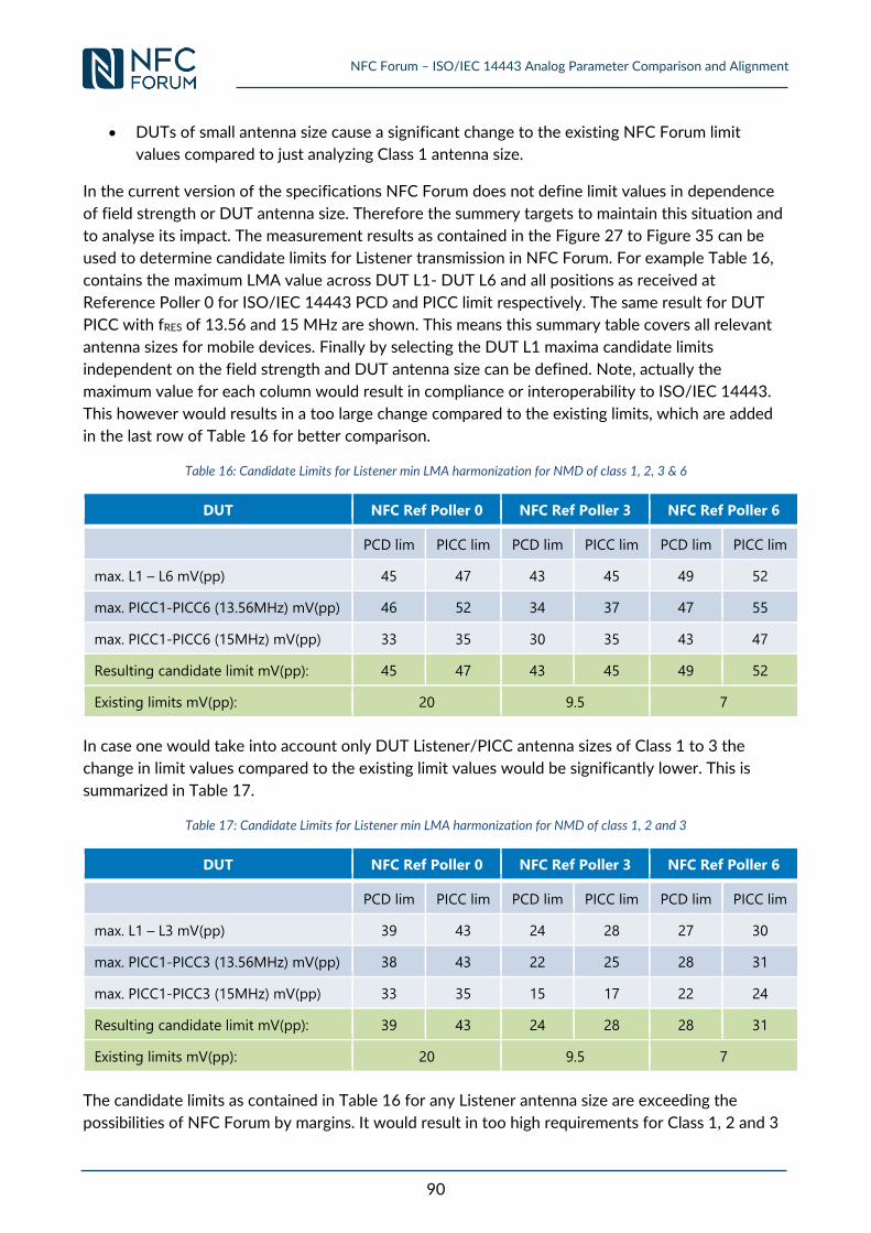
NFC Forum – ISO/IEC 14443 Analog Parameter Comparison and Alignment
90
DUTs of small antenna size cause a significant change to the existing NFC Forum limit
values compared to just analyzing Class 1 antenna size.
In the current version of the specifications NFC Forum does not define limit values in dependence
of field strength or DUT antenna size. Therefore the summery targets to maintain this situation and
to analyse its impact. The measurement results as contained in the Figure 27 to Figure 35 can be
used to determine candidate limits for Listener transmission in NFC Forum. For example Table 16,
contains the maximum LMA value across DUT L1- DUT L6 and all positions as received at
Reference Poller 0 for ISO/IEC 14443 PCD and PICC limit respectively. The same result for DUT
PICC with fRES of 13.56 and 15 MHz are shown. This means this summary table covers all relevant
antenna sizes for mobile devices. Finally by selecting the DUT L1 maxima candidate limits
independent on the field strength and DUT antenna size can be defined. Note, actually the
maximum value for each column would result in compliance or interoperability to ISO/IEC 14443.
This however would results in a too large change compared to the existing limits, which are added
in the last row of Table 16 for better comparison.
Table 16: Candidate Limits for Listener min LMA harmonization for NMD of class 1, 2, 3 & 6
DUT NFC Ref Poller 0 NFC Ref Poller 3 NFC Ref Poller 6
PCD lim PICC lim PCD lim PICC lim PCD lim PICC lim
max. L1 – L6 mV(pp) 45 47 43 45 49 52
max. PICC1-PICC6 (13.56MHz) mV(pp) 46 52 34 37 47 55
max. PICC1-PICC6 (15MHz) mV(pp) 33 35 30 35 43 47
Resulting candidate limit mV(pp): 45 47 43 45 49 52
Existing limits mV(pp): 20 9.5 7
In case one would take into account only DUT Listener/PICC antenna sizes of Class 1 to 3 the
change in limit values compared to the existing limit values would be significantly lower. This is
summarized in Table 17.
Table 17: Candidate Limits for Listener min LMA harmonization for NMD of class 1, 2 and 3
DUT NFC Ref Poller 0 NFC Ref Poller 3 NFC Ref Poller 6
PCD lim PICC lim PCD lim PICC lim PCD lim PICC lim
max. L1 – L3 mV(pp) 39 43 24 28 27 30
max. PICC1-PICC3 (13.56MHz) mV(pp) 38 43 22 25 28 31
max. PICC1-PICC3 (15MHz) mV(pp) 33 35 15 17 22 24
Resulting candidate limit mV(pp): 39 43 24 28 28 31
Existing limits mV(pp): 20 9.5 7
The candidate limits as contained in Table 16 for any Listener antenna size are exceeding the
possibilities of NFC Forum by margins. It would result in too high requirements for Class 1, 2 and 3
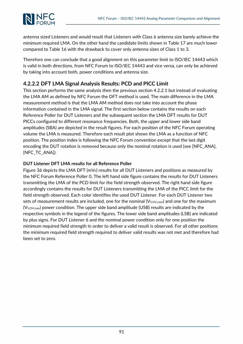
NFC Forum – ISO/IEC 14443 Analog Parameter Comparison and Alignment
91
antenna sized Listeners and would result that Listeners with Class 6 antenna size barely achieve the
minimum required LMA. On the other hand the candidate limits shown in Table 17 are much lower
compared to Table 16 with the drawback to cover only antenna sizes of Class 1 to 3.
Therefore one can conclude that a good alignment on this parameter limit to ISO/IEC 14443 which
is valid in both directions, from NFC Forum to ISO/IEC 14443 and vice versa, can only be achieved
by taking into account both, power conditions and antenna size.
4.2.2.2 DFT LMA Signal Analysis Results: PCD and PICC Limit This section performs the same analysis then the previous section 4.2.2.1 but instead of evaluating
the LMA AM as defined by NFC Forum the DFT method is used. The main difference in the LMA
measurement method is that the LMA AM method does not take into account the phase
information contained in the LMA signal. The first section below contains the results on each
Reference Poller for DUT Listeners and the subsequent section the LMA DFT results for DUT
PICCs configured to different resonance frequencies. Both, the upper and lower side band
amplitudes (SBA) are depicted in the result figures. For each position of the NFC Forum operating
volume the LMA is measured. Therefore each result plot shows the LMA as a function of NFC
position. The position index is following the NFC Forum convention except that the last digit
encoding the DUT rotation is removed because only the nominal rotation is used (see [NFC_ANA],
[NFC_TC_ANA]).
DUT Listener DFT LMA results for all Reference Poller
Figure 36 depicts the LMA DFT (mVP) results for all DUT Listeners and positions as measured by
the NFC Forum Reference Poller 0. The left hand side figure contains the results for DUT Listeners
transmitting the LMA of the PCD limit for the field strength observed. The right hand side figure
accordingly contains the results for DUT Listeners transmitting the LMA of the PICC limit for the
field strength observed. Each color identifies the used DUT Listener. For each DUT Listener two
sets of measurement results are included, one for the nominal (VS,OV,nom) and one for the maximum
(VS,OV,max) power condition. The upper side band amplitude (USB) results are indicated by the
respective symbols in the legend of the figures. The lower side band amplitudes (LSB) are indicated
by plus signs. For DUT Listener 6 and the nominal power condition only for one position the
minimum required field strength in order to deliver a valid result is observed. For all other positions
the minimum required field strength required to deliver valid results was not met and therefore had
been set to zero.
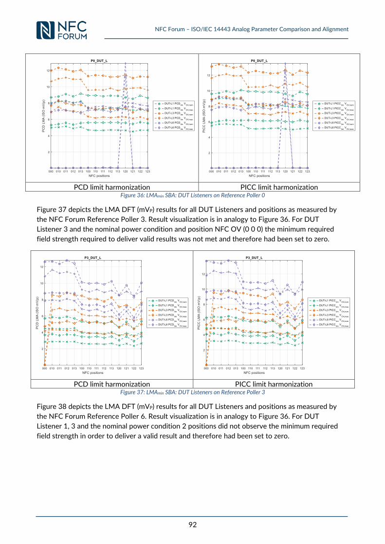
NFC Forum – ISO/IEC 14443 Analog Parameter Comparison and Alignment
92
PCD limit harmonization PICC limit harmonization
Figure 36: LMAmin SBA: DUT Listeners on Reference Poller 0
Figure 37 depicts the LMA DFT (mVP) results for all DUT Listeners and positions as measured by
the NFC Forum Reference Poller 3. Result visualization is in analogy to Figure 36. For DUT
Listener 3 and the nominal power condition and position NFC OV (0 0 0) the minimum required
field strength required to deliver valid results was not met and therefore had been set to zero.
PCD limit harmonization PICC limit harmonization
Figure 37: LMAmin SBA: DUT Listeners on Reference Poller 3
Figure 38 depicts the LMA DFT (mVP) results for all DUT Listeners and positions as measured by
the NFC Forum Reference Poller 6. Result visualization is in analogy to Figure 36. For DUT
Listener 1, 3 and the nominal power condition 2 positions did not observe the minimum required
field strength in order to deliver a valid result and therefore had been set to zero.
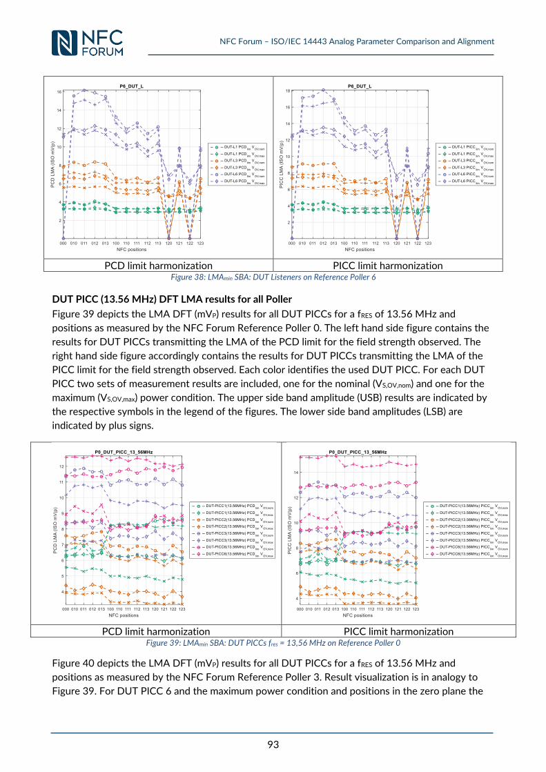
NFC Forum – ISO/IEC 14443 Analog Parameter Comparison and Alignment
93
PCD limit harmonization PICC limit harmonization
Figure 38: LMAmin SBA: DUT Listeners on Reference Poller 6
DUT PICC (13.56 MHz) DFT LMA results for all Poller
Figure 39 depicts the LMA DFT (mVP) results for all DUT PICCs for a fRES of 13.56 MHz and
positions as measured by the NFC Forum Reference Poller 0. The left hand side figure contains the
results for DUT PICCs transmitting the LMA of the PCD limit for the field strength observed. The
right hand side figure accordingly contains the results for DUT PICCs transmitting the LMA of the
PICC limit for the field strength observed. Each color identifies the used DUT PICC. For each DUT
PICC two sets of measurement results are included, one for the nominal (VS,OV,nom) and one for the
maximum (VS,OV,max) power condition. The upper side band amplitude (USB) results are indicated by
the respective symbols in the legend of the figures. The lower side band amplitudes (LSB) are
indicated by plus signs.
PCD limit harmonization PICC limit harmonization
Figure 39: LMAmin SBA: DUT PICCs fres = 13,56 MHz on Reference Poller 0
Figure 40 depicts the LMA DFT (mVP) results for all DUT PICCs for a fRES of 13.56 MHz and
positions as measured by the NFC Forum Reference Poller 3. Result visualization is in analogy to
Figure 39. For DUT PICC 6 and the maximum power condition and positions in the zero plane the
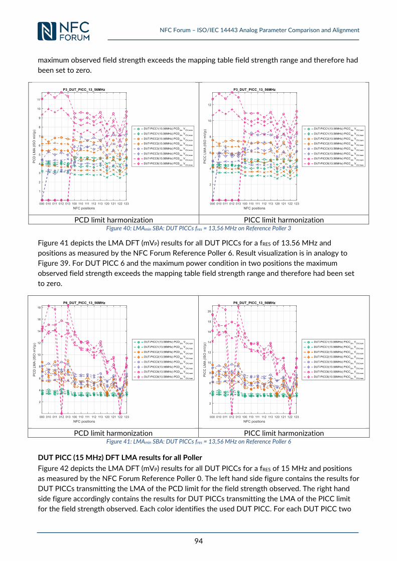
NFC Forum – ISO/IEC 14443 Analog Parameter Comparison and Alignment
94
maximum observed field strength exceeds the mapping table field strength range and therefore had
been set to zero.
PCD limit harmonization PICC limit harmonization
Figure 40: LMAmin SBA: DUT PICCs fres = 13,56 MHz on Reference Poller 3
Figure 41 depicts the LMA DFT (mVP) results for all DUT PICCs for a fRES of 13.56 MHz and
positions as measured by the NFC Forum Reference Poller 6. Result visualization is in analogy to
Figure 39. For DUT PICC 6 and the maximum power condition in two positions the maximum
observed field strength exceeds the mapping table field strength range and therefore had been set
to zero.
PCD limit harmonization PICC limit harmonization
Figure 41: LMAmin SBA: DUT PICCs fres = 13,56 MHz on Reference Poller 6
DUT PICC (15 MHz) DFT LMA results for all Poller
Figure 42 depicts the LMA DFT (mVP) results for all DUT PICCs for a fRES of 15 MHz and positions
as measured by the NFC Forum Reference Poller 0. The left hand side figure contains the results for
DUT PICCs transmitting the LMA of the PCD limit for the field strength observed. The right hand
side figure accordingly contains the results for DUT PICCs transmitting the LMA of the PICC limit
for the field strength observed. Each color identifies the used DUT PICC. For each DUT PICC two
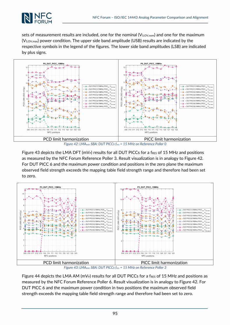
NFC Forum – ISO/IEC 14443 Analog Parameter Comparison and Alignment
95
sets of measurement results are included, one for the nominal (VS,OV,nom) and one for the maximum
(VS,OV,max) power condition. The upper side band amplitude (USB) results are indicated by the
respective symbols in the legend of the figures. The lower side band amplitudes (LSB) are indicated
by plus signs.
PCD limit harmonization PICC limit harmonization
Figure 42: LMAmin SBA: DUT PICCs fres = 15 MHz on Reference Poller 0
Figure 43 depicts the LMA DFT (mVP) results for all DUT PICCs for a fRES of 15 MHz and positions
as measured by the NFC Forum Reference Poller 3. Result visualization is in analogy to Figure 42.
For DUT PICC 6 and the maximum power condition and positions in the zero plane the maximum
observed field strength exceeds the mapping table field strength range and therefore had been set
to zero.
PCD limit harmonization PICC limit harmonization
Figure 43: LMAmin SBA: DUT PICCs fres = 15 MHz on Reference Poller 3
Figure 44 depicts the LMA AM (mVP) results for all DUT PICCs for a fRES of 15 MHz and positions as
measured by the NFC Forum Reference Poller 6. Result visualization is in analogy to Figure 42. For
DUT PICC 6 and the maximum power condition in two positions the maximum observed field
strength exceeds the mapping table field strength range and therefore had been set to zero.
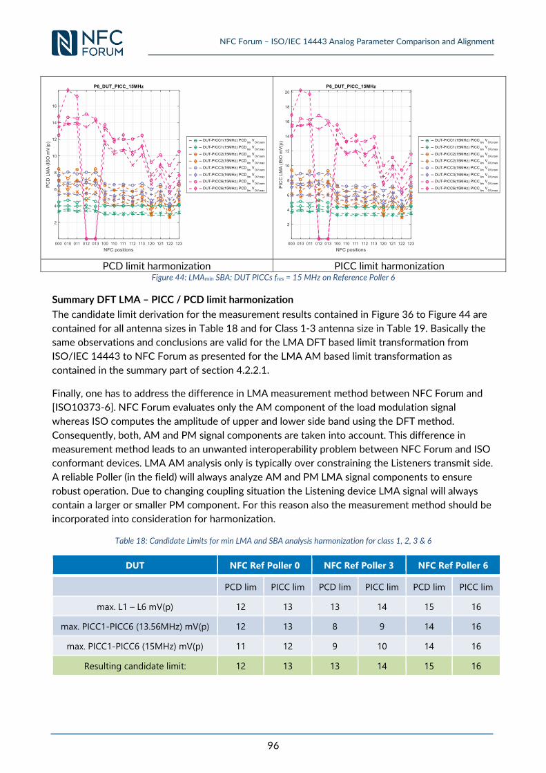
NFC Forum – ISO/IEC 14443 Analog Parameter Comparison and Alignment
96
PCD limit harmonization PICC limit harmonization
Figure 44: LMAmin SBA: DUT PICCs fres = 15 MHz on Reference Poller 6
Summary DFT LMA – PICC / PCD limit harmonization
The candidate limit derivation for the measurement results contained in Figure 36 to Figure 44 are
contained for all antenna sizes in Table 18 and for Class 1-3 antenna size in Table 19. Basically the
same observations and conclusions are valid for the LMA DFT based limit transformation from
ISO/IEC 14443 to NFC Forum as presented for the LMA AM based limit transformation as
contained in the summary part of section 4.2.2.1.
Finally, one has to address the difference in LMA measurement method between NFC Forum and
[ISO10373-6]. NFC Forum evaluates only the AM component of the load modulation signal
whereas ISO computes the amplitude of upper and lower side band using the DFT method.
Consequently, both, AM and PM signal components are taken into account. This difference in
measurement method leads to an unwanted interoperability problem between NFC Forum and ISO
conformant devices. LMA AM analysis only is typically over constraining the Listeners transmit side.
A reliable Poller (in the field) will always analyze AM and PM LMA signal components to ensure
robust operation. Due to changing coupling situation the Listening device LMA signal will always
contain a larger or smaller PM component. For this reason also the measurement method should be
incorporated into consideration for harmonization.
Table 18: Candidate Limits for min LMA and SBA analysis harmonization for class 1, 2, 3 & 6
DUT NFC Ref Poller 0 NFC Ref Poller 3 NFC Ref Poller 6
PCD lim PICC lim PCD lim PICC lim PCD lim PICC lim
max. L1 – L6 mV(p) 12 13 13 14 15 16
max. PICC1-PICC6 (13.56MHz) mV(p) 12 13 8 9 14 16
max. PICC1-PICC6 (15MHz) mV(p) 11 12 9 10 14 16
Resulting candidate limit: 12 13 13 14 15 16
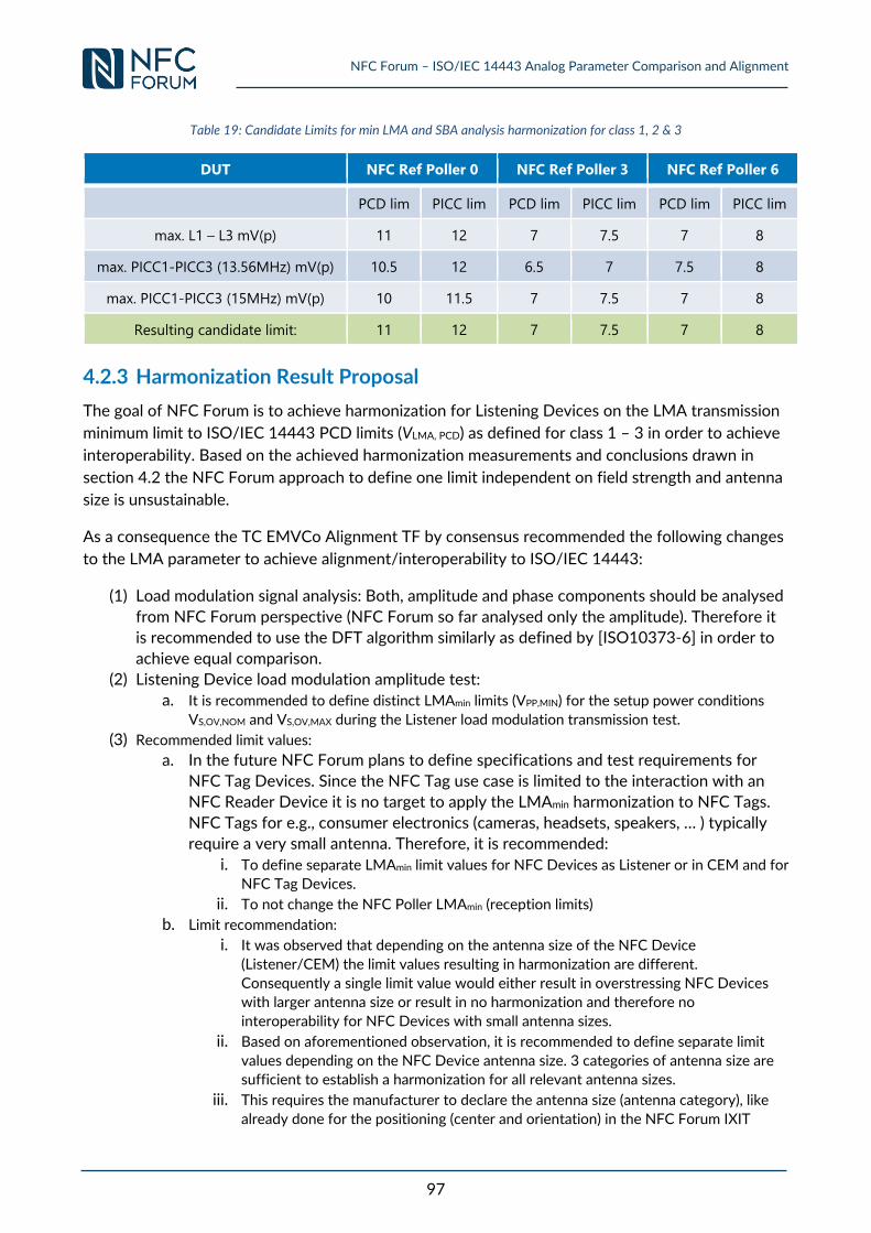
NFC Forum – ISO/IEC 14443 Analog Parameter Comparison and Alignment
97
Table 19: Candidate Limits for min LMA and SBA analysis harmonization for class 1, 2 & 3
DUT NFC Ref Poller 0 NFC Ref Poller 3 NFC Ref Poller 6
PCD lim PICC lim PCD lim PICC lim PCD lim PICC lim
max. L1 – L3 mV(p) 11 12 7 7.5 7 8
max. PICC1-PICC3 (13.56MHz) mV(p) 10.5 12 6.5 7 7.5 8
max. PICC1-PICC3 (15MHz) mV(p) 10 11.5 7 7.5 7 8
Resulting candidate limit: 11 12 7 7.5 7 8
4.2.3 Harmonization Result Proposal
The goal of NFC Forum is to achieve harmonization for Listening Devices on the LMA transmission
minimum limit to ISO/IEC 14443 PCD limits (VLMA, PCD) as defined for class 1 – 3 in order to achieve
interoperability. Based on the achieved harmonization measurements and conclusions drawn in
section 4.2 the NFC Forum approach to define one limit independent on field strength and antenna
size is unsustainable.
As a consequence the TC EMVCo Alignment TF by consensus recommended the following changes
to the LMA parameter to achieve alignment/interoperability to ISO/IEC 14443:
(1) Load modulation signal analysis: Both, amplitude and phase components should be analysed
from NFC Forum perspective (NFC Forum so far analysed only the amplitude). Therefore it
is recommended to use the DFT algorithm similarly as defined by [ISO10373-6] in order to
achieve equal comparison.
(2) Listening Device load modulation amplitude test:
a. It is recommended to define distinct LMAmin limits (VPP,MIN) for the setup power conditions
VS,OV,NOM and VS,OV,MAX during the Listener load modulation transmission test.
(3) Recommended limit values:
a. In the future NFC Forum plans to define specifications and test requirements for
NFC Tag Devices. Since the NFC Tag use case is limited to the interaction with an
NFC Reader Device it is no target to apply the LMAmin harmonization to NFC Tags.
NFC Tags for e.g., consumer electronics (cameras, headsets, speakers, … ) typically
require a very small antenna. Therefore, it is recommended:
i. To define separate LMAmin limit values for NFC Devices as Listener or in CEM and for
NFC Tag Devices.
ii. To not change the NFC Poller LMAmin (reception limits)
b. Limit recommendation:
i. It was observed that depending on the antenna size of the NFC Device
(Listener/CEM) the limit values resulting in harmonization are different.
Consequently a single limit value would either result in overstressing NFC Devices
with larger antenna size or result in no harmonization and therefore no
interoperability for NFC Devices with small antenna sizes.
ii. Based on aforementioned observation, it is recommended to define separate limit
values depending on the NFC Device antenna size. 3 categories of antenna size are
sufficient to establish a harmonization for all relevant antenna sizes.
iii. This requires the manufacturer to declare the antenna size (antenna category), like
already done for the positioning (center and orientation) in the NFC Forum IXIT
NFC Forum – ISO/IEC 14443 Analog Parameter Comparison and Alignment
98
(Implementation eXtra Information for Testing) document required for analog
certification.
The recommended changes are summarized as follows:
Usage of DFT for LMA analysis: Compute PASS/FAIL verdict by calculating the average of
upper and lower side band
Define separate LMAmin limit values for NFC Devices as Listener or in CEM and NFC Tag
Devices. Define antenna size dependent LMAmin limit values for NFC Devices: 3 categories are
proposed
Separate Listener limits LMAmin (VPP,min) for power conditions VS,OV,NOM and VS,OV,MAX
Unchanged LMAmin limit values for Polling Device reception tests
In contrast to ISO/IEC 10373-6 NFC Forum does not compute the LMA as the minimum of USB
and LSB but instead computes the average of USB and LSB. Main reason for this difference is the
difference in measurement equipment used for testing. ISO/IEC 10373-6 uses the Test PCD
Assembly to measure the PICC LMA. In particular the sense coils capture the PICC transmission.
The sense coils are wide band in frequency and therefore have no or only a negligible influence on
the signal. Additionally, the sense coils are arranged in a way that they perform a spatial filtering
and thus mainly capture the PICC transmission. In contrast NFC Forum measurement methodology
is closer to the real case seen in the field. NFC Forum receives the PICC transmission directly via
the Reference Poller antenna. In particular the voltage drop across the quality damping resistor is
measured. This means the observed PICC transmission is shaped by the Reference Poller transfer
function of the receive path. This transfer function is changing as a function of the coupling and fRES
of the DUT Listener or DUT PICC. For this reason the absolute value of LSB and USB has not the
same meaning compared to ISO/IEC 14443 since the levels of USB and LSB are shifting in
dependence of coupling and the DUT Listener fRES. The average of USB and LSB was shown to be a
good candidate to resolve the level shifting between USB and LSB. In case an ISO compliant PCD
uses a single side band receiver or amplifies one side band a reduction of the operating distance
may be observed. Future harmonization work will address the side band amplitude to VLMA (LMAmin)
computation difference. The recommended LMAmin candidate limit values using the DFT method
(mVP) are shown in Table 20. For the NFC Forum Devices 3 antenna categories (CAT) are
introduced and shown on the right hand side of Table 20. CAT A covers Class 1antenna sizes, CAT
B covers antenna sizes smaller than class 1 and equal to or larger than Class 3. CAT C is defined for
all antenna size smaller than Class 3 and is represented by a Class 6 antenna size. Moreover, any
antenna size which does not fit into CAT A or B belongs to CAT C.
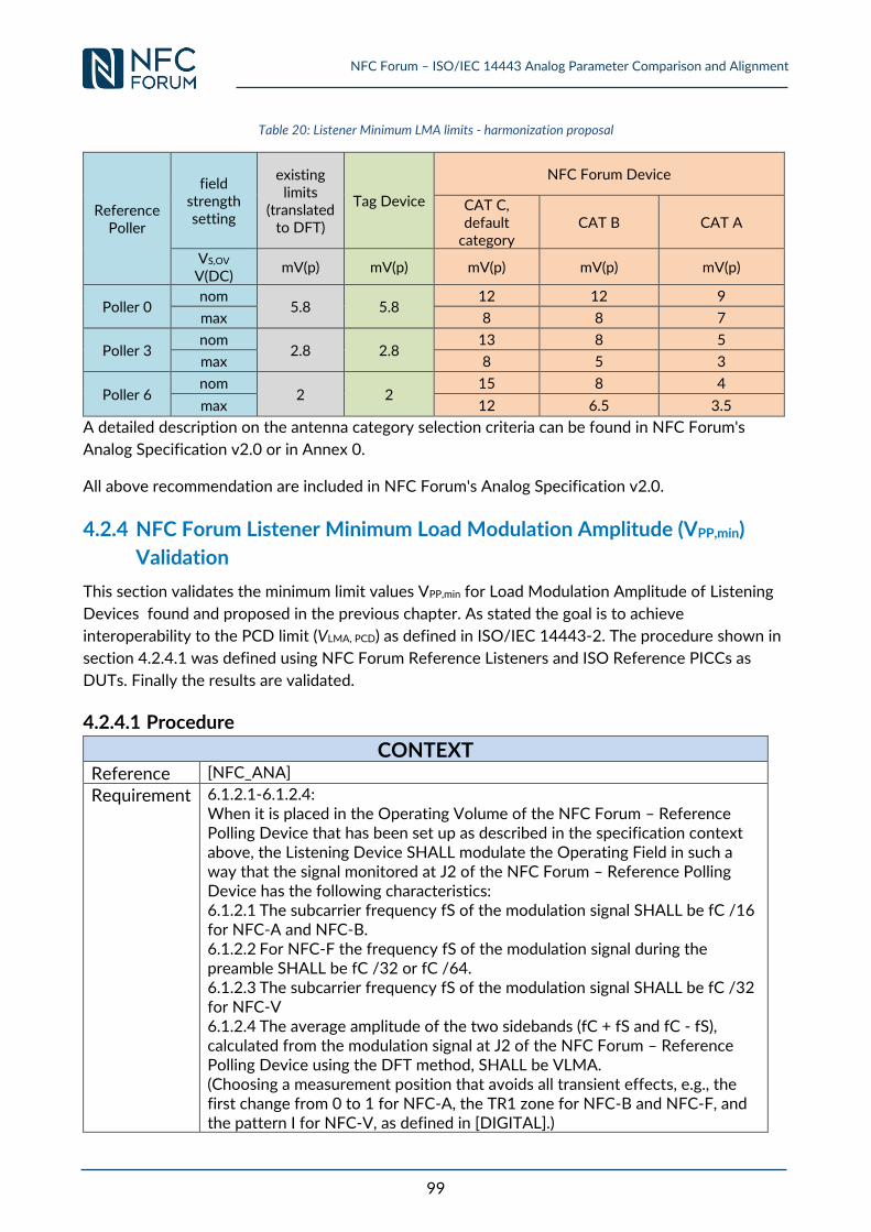
NFC Forum – ISO/IEC 14443 Analog Parameter Comparison and Alignment
99
Table 20: Listener Minimum LMA limits - harmonization proposal
Reference Poller
field strength setting
existing limits
(translated to DFT)
Tag Device
NFC Forum Device
CAT C, default
category CAT B CAT A
VS,OV V(DC)
mV(p) mV(p) mV(p) mV(p) mV(p)
Poller 0 nom
5.8 5.8 12 12 9
max 8 8 7
Poller 3 nom
2.8 2.8 13 8 5
max 8 5 3
Poller 6 nom
2 2 15 8 4
max 12 6.5 3.5
A detailed description on the antenna category selection criteria can be found in NFC Forum's
Analog Specification v2.0 or in Annex 0.
All above recommendation are included in NFC Forum's Analog Specification v2.0.
4.2.4 NFC Forum Listener Minimum Load Modulation Amplitude (VPP,min)
Validation
This section validates the minimum limit values VPP,min for Load Modulation Amplitude of Listening
Devices found and proposed in the previous chapter. As stated the goal is to achieve
interoperability to the PCD limit (VLMA, PCD) as defined in ISO/IEC 14443-2. The procedure shown in
section 4.2.4.1 was defined using NFC Forum Reference Listeners and ISO Reference PICCs as
DUTs. Finally the results are validated.
4.2.4.1 Procedure
CONTEXT
Reference [NFC_ANA]
Requirement 6.1.2.1-6.1.2.4: When it is placed in the Operating Volume of the NFC Forum – Reference Polling Device that has been set up as described in the specification context above, the Listening Device SHALL modulate the Operating Field in such a way that the signal monitored at J2 of the NFC Forum – Reference Polling Device has the following characteristics: 6.1.2.1 The subcarrier frequency fS of the modulation signal SHALL be fC /16 for NFC-A and NFC-B. 6.1.2.2 For NFC-F the frequency fS of the modulation signal during the preamble SHALL be fC /32 or fC /64. 6.1.2.3 The subcarrier frequency fS of the modulation signal SHALL be fC /32 for NFC-V 6.1.2.4 The average amplitude of the two sidebands (fC + fS and fC - fS), calculated from the modulation signal at J2 of the NFC Forum – Reference Polling Device using the DFT method, SHALL be VLMA. (Choosing a measurement position that avoids all transient effects, e.g., the first change from 0 to 1 for NFC-A, the TR1 zone for NFC-B and NFC-F, and the pattern I for NFC-V, as defined in [DIGITAL].)
NFC Forum – ISO/IEC 14443 Analog Parameter Comparison and Alignment
100
Refer to Appendix B.2 for the value of VLMA and to Appendix B.4 for the definition of antenna category.
Implicit Requirement
Minimum load modulation amplitude harmonization result validation
Question Is an NFC Forum Device in Listen mode which is compliant for the above minimum load modulation transmission requirement also compliant or interoperable to the corresponding minimum ISO PICC Requirement?
PROCEDURE Step SETUP
1 Setup the NFC Forum – Reference Poller 0 to nominal field strength (VS,OV,nom).
2
Setup the DUT L1 (loading 330Ω) in order to get listener minimum load
modulation value (see Table 20 – CAT A) in each position of the NFC OV when measured at the J2 output of the NFC Forum – Reference Poller 0. Record VOV (loading 330Ω) and the load modulator input voltage for each
position of the NFC OV.
3 Setup the NFC Forum – Reference Poller 3 to nominal field strength (VS,OV,nom).
4
Setup the DUT L1 (loading 330Ω) in order to get listener minimum load
modulation value (see Table 20 – CAT A) in each position of the NFC OV when measured at the J2 output of the NFC Forum – Reference Poller 3. Record VOV (loading 330Ω) and the load modulator input voltage for each
position of the NFC OV. 5 Setup the NFC Forum – Reference Poller 6 to nominal field strength.
6
Setup the DUT L1 (loading 330Ω) in order to get listener minimum load
modulation value (see Table 20 – CAT A) in each position of the NFC OV when measured at the J2 output of the NFC Forum – Reference Poller 6. Record VOV (loading 330Ω) and the load modulator input voltage for each
position of the NFC OV.
7
Repeat the procedure above with: DUT L1 (CAT A, 820 Ω),
DUT L3 (CAT B, 330 Ω and 820 Ω),
DUT L6 (CAT C, 330 Ω and 820 Ω),
DUT PICC 1 (fRES of 13.56, 15 and 16.5 MHz) for CAT A, DUT PICC 2 (fRES of 13.56, 15 and 16.5 MHz) for CAT B, DUT PICC 3 (fRES of 13.56, 15 and 16.5 MHz) for CAT B, DUT PICC 6 (fRES of 13.56, 15 and 16.5 MHz) for CAT C.
Step VERIFICATION
1 Place DUT L1 (820 Ω) in the DUT position of the respective Test PCD
Assembly.
2 Readjust the field strength until the VOV as measured at respective DUTListener/ DUT PICC in each of the NFC Forum – Reference Poller test positions is reached.
NFC Forum – ISO/IEC 14443 Analog Parameter Comparison and Alignment
101
3 Set the load modulator input voltage for the position (SETUP Steps 2) , 4) and 6) ) and measure the load modulation amplitude.
4
Repeat the VERIFICATION steps with:DUT L1 (330 Ω)
DUT L3 (330 Ω and 820 Ω)
DUT L6 (330 Ω and 820 Ω)
DUT PICC 1 (fRES of 13.56, 15 and 16.5 MHz) for CAT A, DUT PICC 2 (fRES of 13.56, 15 and 16.5 MHz) for CAT B, DUT PICC 3 (fRES of 13.56, 15 and 16.5 MHz) for CAT B, DUT PICC 6 (fRES of 13.56, 15 and 16.5 MHz) for CAT C.
5
Repeat the complete SETUP and VERIFICATION steps with VS,OV,MAX in SETUP steps 1, 3 and 5. Note: This analysis assumes the NFC Forum Analog specification defines the Load
modulation amplitude limits independent of position within the NFC OV and field strength.
EXPECTED OUTCOME
Step COMPLIANCY
1 Compare the measured load modulation amplitude of VERIFICATION step 3 to the ISO PICC minimum load modulation amplitude (see Table
27).
Step INTEROPERABILITY
1 Compare the measured load modulation amplitude of VERIFICATION step 3 to the ISO PCD minimum load modulation amplitude (see Table
24).
CONCLUSION / DISCUSSION
Results are presented in section 4.2.4.2 and a discussion is performed in section 4.2.5.
4.2.4.2 Validation Results Validation results are presented using the following Reference Equipment and configurations
emulating DUTs:
NFC Forum Reference Listener 1, 3 and 6 with loading 330Ω
NFC Forum Reference Listener 1, 3 and 6 with loading 820Ω
Reference PICCs 1 – 3 and 6 and resonance frequency 13,56MHz
Reference PICCs 1 – 3 and 6 and resonance frequency 15MHz
Reference PICCs 1 – 3 and 6 and resonance frequency 16,5MHz
The DUT configurations used for validation represent a real DUT Listener and DUT PICCs in the
field. The analysis considered a representative range of antenna sizes with different loadings and
resonance frequencies. The validation results contained in Figure 45 - Figure 64 are all depicted as
side band amplitude using the DFT method versus field strength. All result plots contain the LMAmin
PCD (VLMA, PCD) and PICC (VLMA, PICC) limits versus field strength for Class 1 and Class 2-3 as defined
in [ISO14443-2]and [ISO14443-2:AMD2] (see also Table 24 and Table 27). Also the EMD limit
versus field strength is indicated in orange colour (see [ISO14443-2:AMD1] and section 0 for a
definition). Additionally, DUTs of Class 6 results are provided when measured with Test PCD
Assembly 2 as required for Class 6 (see [ISO14443-2:AMD2] and [ISO10373-6:AMD1]).
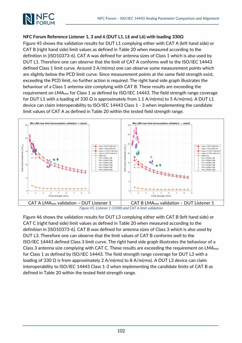
NFC Forum – ISO/IEC 14443 Analog Parameter Comparison and Alignment
102
NFC Forum Reference Listener 1, 3 and 6 (DUT L1, L§ and L6) with loading 330Ω
Figure 45 shows the validation results for DUT L1 complying either with CAT A (left hand side) or
CAT B (right hand side) limit values as defined in Table 20 when measured according to the
definition in [ISO10373-6]. CAT A was defined for antenna sizes of Class 1 which is also used by
DUT L1. Therefore one can observe that the limit of CAT A conforms well to the ISO/IEC 14443
defined Class 1 limit curve. Around 3 A/m(rms) one can observe some measurement points which
are slightly below the PCD limit curve. Since measurement points at the same field strength exist,
exceeding the PCD limit, no further action is required. The right hand side graph illustrates the
behaviour of a Class 1 antenna size complying with CAT B. These results are exceeding the
requirement on LMAmin for Class 1 as defined by ISO/IEC 14443. The field strength range coverage
for DUT L1 with a loading of 330 Ω is approximately from 1.1 A/m(rms) to 5 A/m(rms). A DUT L1
device can claim interoperability to ISO/IEC 14443 Class 1 - 3 when implementing the candidate
limit values of CAT A as defined in Table 20 within the tested field strength range.
CAT A LMAmin validation – DUT Listener 1 CAT B LMAmin validation – DUT Listener 1
Figure 45: Listener 1 (330R) and CAT A limit validation
Figure 46 shows the validation results for DUT L3 complying either with CAT B (left hand side) or
CAT C (right hand side) limit values as defined in Table 20 when measured according to the
definition in [ISO10373-6]. CAT B was defined for antenna sizes of Class 3 which is also used by
DUT L3. Therefore one can observe that the limit values of CAT B conforms well to the
ISO/IEC 14443 defined Class 3 limit curve. The right hand side graph illustrates the behaviour of a
Class 3 antenna size complying with CAT C. These results are exceeding the requirement on LMAmin
for Class 1 as defined by ISO/IEC 14443. The field strength range coverage for DUT L3 with a
loading of 330 Ω is from approximately 2 A/m(rms) to 8 A/m(rms). A DUT L3 device can claim
interoperability to ISO/IEC 14443 Class 1-3 when implementing the candidate limits of CAT B as
defined in Table 20 within the tested field strength range.
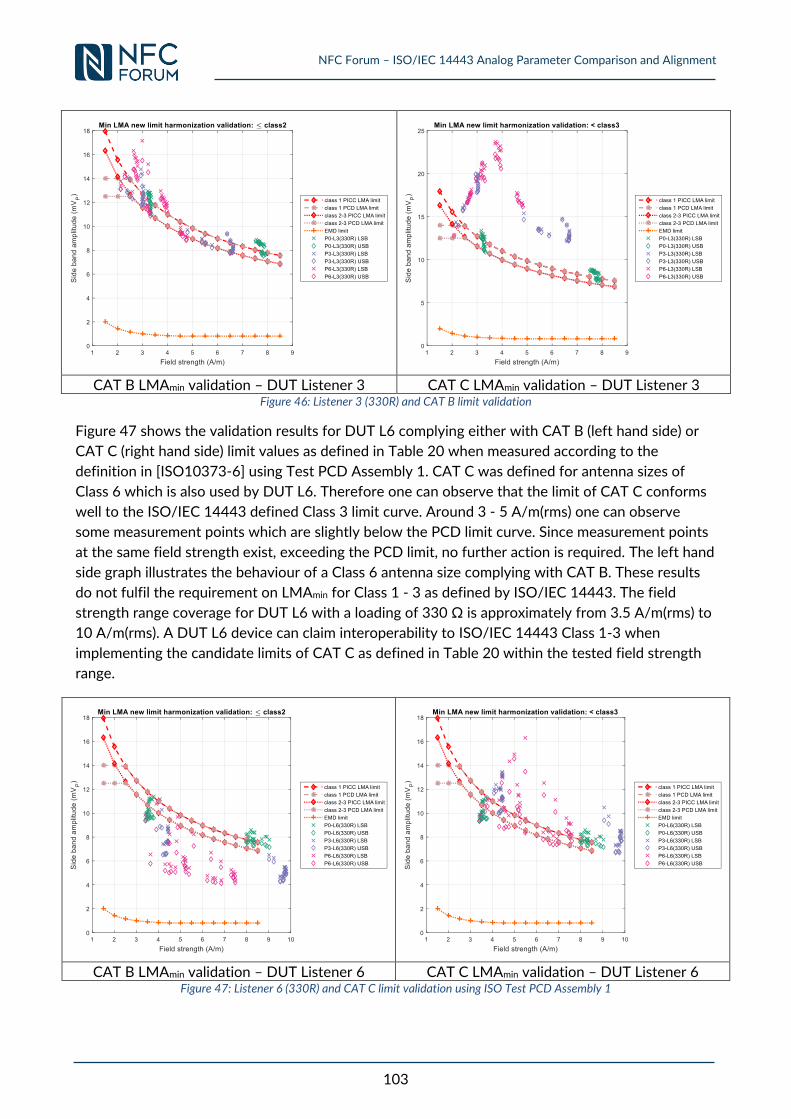
NFC Forum – ISO/IEC 14443 Analog Parameter Comparison and Alignment
103
CAT B LMAmin validation – DUT Listener 3 CAT C LMAmin validation – DUT Listener 3
Figure 46: Listener 3 (330R) and CAT B limit validation
Figure 47 shows the validation results for DUT L6 complying either with CAT B (left hand side) or
CAT C (right hand side) limit values as defined in Table 20 when measured according to the
definition in [ISO10373-6] using Test PCD Assembly 1. CAT C was defined for antenna sizes of
Class 6 which is also used by DUT L6. Therefore one can observe that the limit of CAT C conforms
well to the ISO/IEC 14443 defined Class 3 limit curve. Around 3 - 5 A/m(rms) one can observe
some measurement points which are slightly below the PCD limit curve. Since measurement points
at the same field strength exist, exceeding the PCD limit, no further action is required. The left hand
side graph illustrates the behaviour of a Class 6 antenna size complying with CAT B. These results
do not fulfil the requirement on LMAmin for Class 1 - 3 as defined by ISO/IEC 14443. The field
strength range coverage for DUT L6 with a loading of 330 Ω is approximately from 3.5 A/m(rms) to
10 A/m(rms). A DUT L6 device can claim interoperability to ISO/IEC 14443 Class 1-3 when
implementing the candidate limits of CAT C as defined in Table 20 within the tested field strength
range.
CAT B LMAmin validation – DUT Listener 6 CAT C LMAmin validation – DUT Listener 6
Figure 47: Listener 6 (330R) and CAT C limit validation using ISO Test PCD Assembly 1
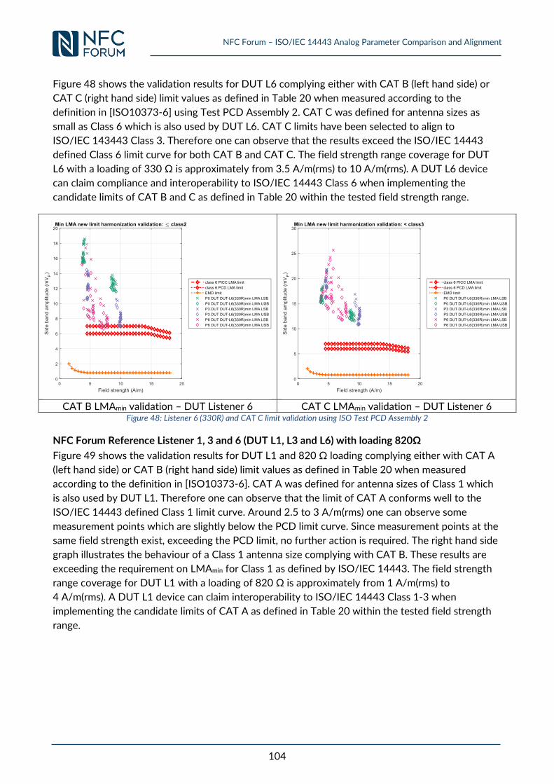
NFC Forum – ISO/IEC 14443 Analog Parameter Comparison and Alignment
104
Figure 48 shows the validation results for DUT L6 complying either with CAT B (left hand side) or
CAT C (right hand side) limit values as defined in Table 20 when measured according to the
definition in [ISO10373-6] using Test PCD Assembly 2. CAT C was defined for antenna sizes as
small as Class 6 which is also used by DUT L6. CAT C limits have been selected to align to
ISO/IEC 143443 Class 3. Therefore one can observe that the results exceed the ISO/IEC 14443
defined Class 6 limit curve for both CAT B and CAT C. The field strength range coverage for DUT
L6 with a loading of 330 Ω is approximately from 3.5 A/m(rms) to 10 A/m(rms). A DUT L6 device
can claim compliance and interoperability to ISO/IEC 14443 Class 6 when implementing the
candidate limits of CAT B and C as defined in Table 20 within the tested field strength range.
CAT B LMAmin validation – DUT Listener 6 CAT C LMAmin validation – DUT Listener 6
Figure 48: Listener 6 (330R) and CAT C limit validation using ISO Test PCD Assembly 2
NFC Forum Reference Listener 1, 3 and 6 (DUT L1, L3 and L6) with loading 820Ω
Figure 49 shows the validation results for DUT L1 and 820 Ω loading complying either with CAT A
(left hand side) or CAT B (right hand side) limit values as defined in Table 20 when measured
according to the definition in [ISO10373-6]. CAT A was defined for antenna sizes of Class 1 which
is also used by DUT L1. Therefore one can observe that the limit of CAT A conforms well to the
ISO/IEC 14443 defined Class 1 limit curve. Around 2.5 to 3 A/m(rms) one can observe some
measurement points which are slightly below the PCD limit curve. Since measurement points at the
same field strength exist, exceeding the PCD limit, no further action is required. The right hand side
graph illustrates the behaviour of a Class 1 antenna size complying with CAT B. These results are
exceeding the requirement on LMAmin for Class 1 as defined by ISO/IEC 14443. The field strength
range coverage for DUT L1 with a loading of 820 Ω is approximately from 1 A/m(rms) to
4 A/m(rms). A DUT L1 device can claim interoperability to ISO/IEC 14443 Class 1-3 when
implementing the candidate limits of CAT A as defined in Table 20 within the tested field strength
range.
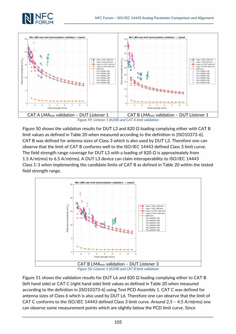
NFC Forum – ISO/IEC 14443 Analog Parameter Comparison and Alignment
105
CAT A LMAmin validation – DUT Listener 1 CAT B LMAmin validation – DUT Listener 1
Figure 49: Listener 1 (820R) and CAT A limit validation
Figure 50 shows the validation results for DUT L3 and 820 Ω loading complying either with CAT B
limit values as defined in Table 20 when measured according to the definition in [ISO10373-6].
CAT B was defined for antenna sizes of Class 3 which is also used by DUT L3. Therefore one can
observe that the limit of CAT B conforms well to the ISO/IEC 14443 defined Class 3 limit curve.
The field strength range coverage for DUT L3 with a loading of 820 Ω is approximately from
1.5 A/m(rms) to 6.5 A/m(rms). A DUT L3 device can claim interoperability to ISO/IEC 14443
Class 1-3 when implementing the candidate limits of CAT B as defined in Table 20 within the tested
field strength range.
CAT B LMAmin validation – DUT Listener 3 Figure 50: Listener 3 (820R) and CAT B limit validation
Figure 51 shows the validation results for DUT L6 and 820 Ω loading complying either to CAT B
(left hand side) or CAT C (right hand side) limit values as defined in Table 20 when measured
according to the definition in [ISO10373-6] using Test PCD Assembly 1. CAT C was defined for
antenna sizes of Class 6 which is also used by DUT L6. Therefore one can observe that the limit of
CAT C conforms to the ISO/IEC 14443 defined Class 3 limit curve. Around 2.5 – 4.5 A/m(rms) one
can observe some measurement points which are slightly below the PCD limit curve. Since
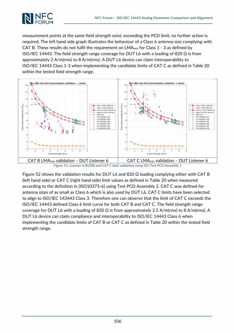
NFC Forum – ISO/IEC 14443 Analog Parameter Comparison and Alignment
106
measurement points at the same field strength exist, exceeding the PCD limit, no further action is
required. The left hand side graph illustrates the behaviour of a Class 6 antenna size complying with
CAT B. These results do not fulfil the requirement on LMAmin for Class 1 - 3 as defined by
ISO/IEC 14443. The field strength range coverage for DUT L6 with a loading of 820 Ω is from
approximately 2 A/m(rms) to 8 A/m(rms). A DUT L6 device can claim interoperability to
ISO/IEC 14443 Class 1-3 when implementing the candidate limits of CAT C as defined in Table 20
within the tested field strength range.
CAT B LMAmin validation – DUT Listener 6 CAT C LMAmin validation – DUT Listener 6
Figure 51: Listener 6 (820R) and CAT C limit validation using ISO Test PCD Assembly 1
Figure 52 shows the validation results for DUT L6 and 820 Ω loading complying either with CAT B
(left hand side) or CAT C (right hand side) limit values as defined in Table 20 when measured
according to the definition in [ISO10373-6] using Test PCD Assembly 2. CAT C was defined for
antenna sizes of as small as Class 6 which is also used by DUT L6. CAT C limits have been selected
to align to ISO/IEC 143443 Class 3. Therefore one can observe that the limit of CAT C exceeds the
ISO/IEC 14443 defined Class 6 limit curve for both CAT B and CAT C. The field strength range
coverage for DUT L6 with a loading of 820 Ω is from approximately 2.5 A/m(rms) to 8 A/m(rms). A
DUT L6 device can claim compliance and interoperability to ISO/IEC 14443 Class 6 when
implementing the candidate limits of CAT B or CAT C as defined in Table 20 within the tested field
strength range.
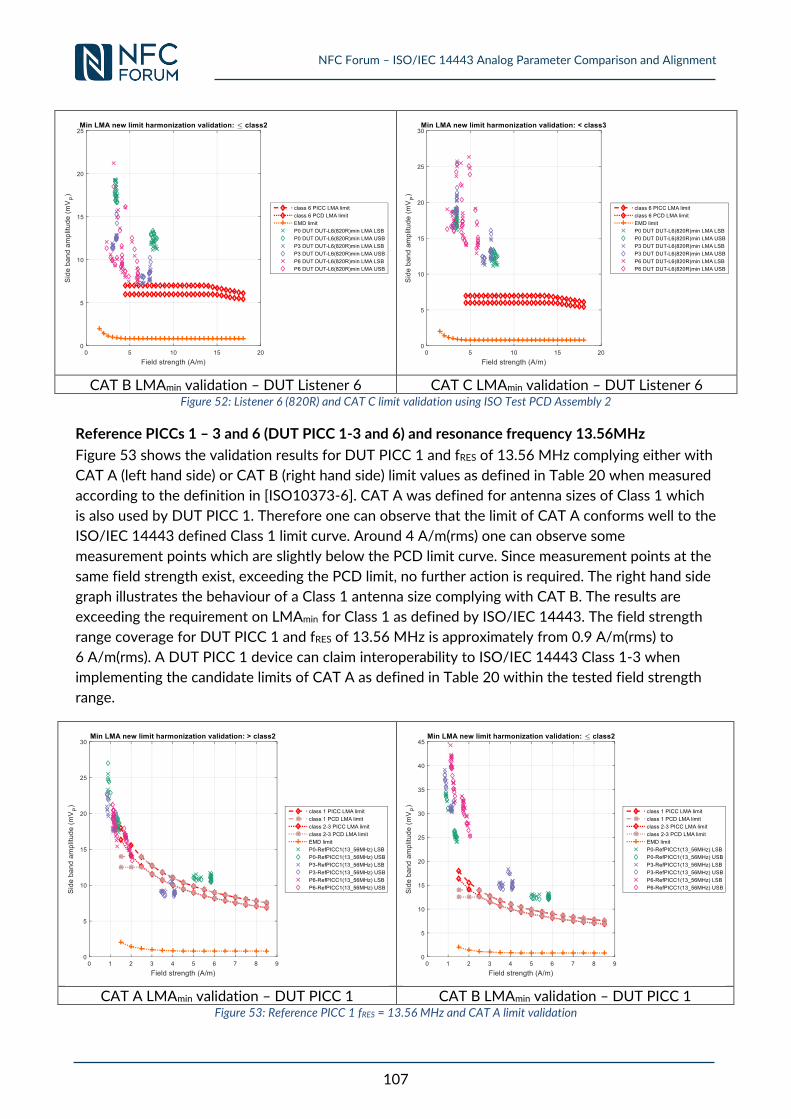
NFC Forum – ISO/IEC 14443 Analog Parameter Comparison and Alignment
107
CAT B LMAmin validation – DUT Listener 6 CAT C LMAmin validation – DUT Listener 6
Figure 52: Listener 6 (820R) and CAT C limit validation using ISO Test PCD Assembly 2
Reference PICCs 1 – 3 and 6 (DUT PICC 1-3 and 6) and resonance frequency 13.56MHz
Figure 53 shows the validation results for DUT PICC 1 and fRES of 13.56 MHz complying either with
CAT A (left hand side) or CAT B (right hand side) limit values as defined in Table 20 when measured
according to the definition in [ISO10373-6]. CAT A was defined for antenna sizes of Class 1 which
is also used by DUT PICC 1. Therefore one can observe that the limit of CAT A conforms well to the
ISO/IEC 14443 defined Class 1 limit curve. Around 4 A/m(rms) one can observe some
measurement points which are slightly below the PCD limit curve. Since measurement points at the
same field strength exist, exceeding the PCD limit, no further action is required. The right hand side
graph illustrates the behaviour of a Class 1 antenna size complying with CAT B. The results are
exceeding the requirement on LMAmin for Class 1 as defined by ISO/IEC 14443. The field strength
range coverage for DUT PICC 1 and fRES of 13.56 MHz is approximately from 0.9 A/m(rms) to
6 A/m(rms). A DUT PICC 1 device can claim interoperability to ISO/IEC 14443 Class 1-3 when
implementing the candidate limits of CAT A as defined in Table 20 within the tested field strength
range.
CAT A LMAmin validation – DUT PICC 1 CAT B LMAmin validation – DUT PICC 1
Figure 53: Reference PICC 1 fRES = 13.56 MHz and CAT A limit validation
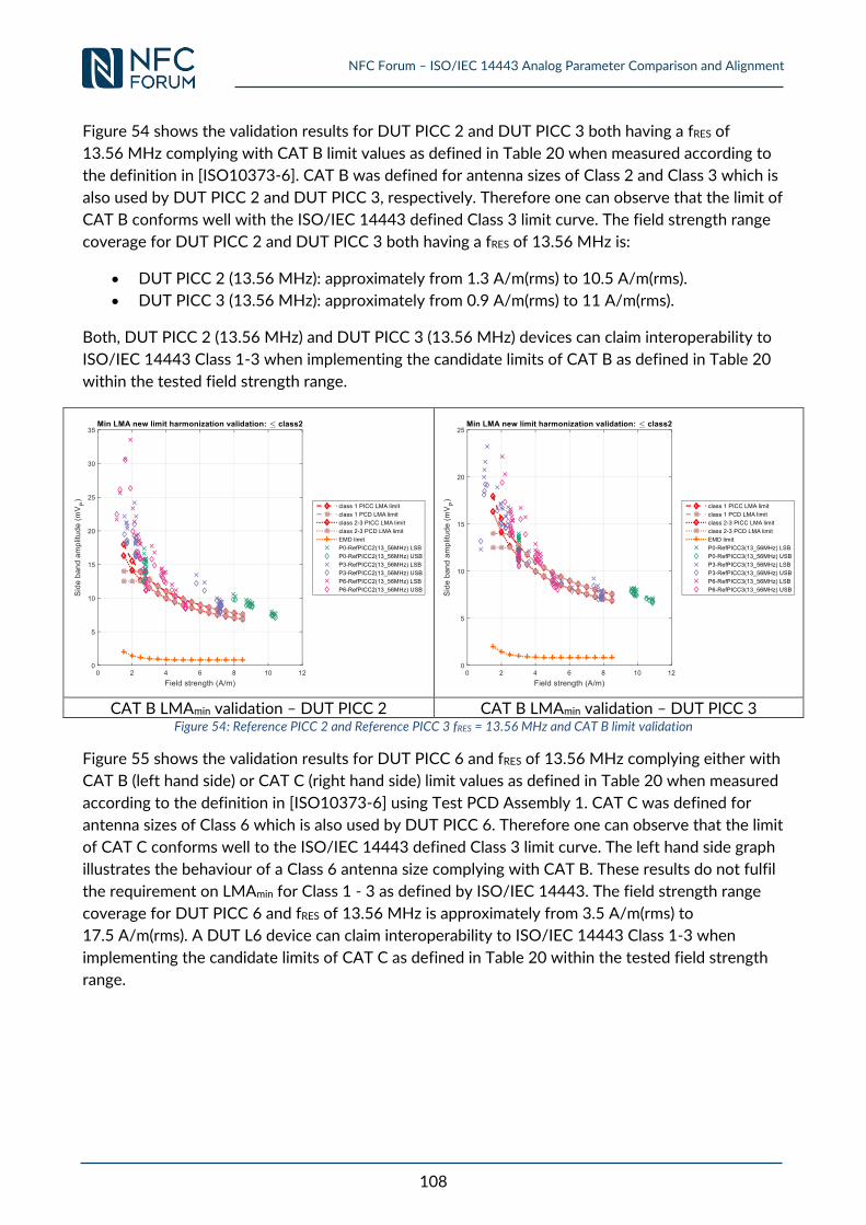
NFC Forum – ISO/IEC 14443 Analog Parameter Comparison and Alignment
108
Figure 54 shows the validation results for DUT PICC 2 and DUT PICC 3 both having a fRES of
13.56 MHz complying with CAT B limit values as defined in Table 20 when measured according to
the definition in [ISO10373-6]. CAT B was defined for antenna sizes of Class 2 and Class 3 which is
also used by DUT PICC 2 and DUT PICC 3, respectively. Therefore one can observe that the limit of
CAT B conforms well with the ISO/IEC 14443 defined Class 3 limit curve. The field strength range
coverage for DUT PICC 2 and DUT PICC 3 both having a fRES of 13.56 MHz is:
DUT PICC 2 (13.56 MHz): approximately from 1.3 A/m(rms) to 10.5 A/m(rms).
DUT PICC 3 (13.56 MHz): approximately from 0.9 A/m(rms) to 11 A/m(rms).
Both, DUT PICC 2 (13.56 MHz) and DUT PICC 3 (13.56 MHz) devices can claim interoperability to
ISO/IEC 14443 Class 1-3 when implementing the candidate limits of CAT B as defined in Table 20
within the tested field strength range.
CAT B LMAmin validation – DUT PICC 2 CAT B LMAmin validation – DUT PICC 3
Figure 54: Reference PICC 2 and Reference PICC 3 fRES = 13.56 MHz and CAT B limit validation
Figure 55 shows the validation results for DUT PICC 6 and fRES of 13.56 MHz complying either with
CAT B (left hand side) or CAT C (right hand side) limit values as defined in Table 20 when measured
according to the definition in [ISO10373-6] using Test PCD Assembly 1. CAT C was defined for
antenna sizes of Class 6 which is also used by DUT PICC 6. Therefore one can observe that the limit
of CAT C conforms well to the ISO/IEC 14443 defined Class 3 limit curve. The left hand side graph
illustrates the behaviour of a Class 6 antenna size complying with CAT B. These results do not fulfil
the requirement on LMAmin for Class 1 - 3 as defined by ISO/IEC 14443. The field strength range
coverage for DUT PICC 6 and fRES of 13.56 MHz is approximately from 3.5 A/m(rms) to
17.5 A/m(rms). A DUT L6 device can claim interoperability to ISO/IEC 14443 Class 1-3 when
implementing the candidate limits of CAT C as defined in Table 20 within the tested field strength
range.
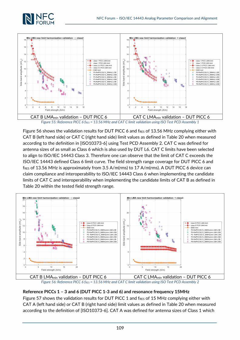
NFC Forum – ISO/IEC 14443 Analog Parameter Comparison and Alignment
109
CAT B LMAmin validation – DUT PICC 6 CAT C LMAmin validation – DUT PICC 6
Figure 55: Reference PICC 6 fRES = 13.56 MHz and CAT C limit validation using ISO Test PCD Assembly 1
Figure 56 shows the validation results for DUT PICC 6 and fRES of 13.56 MHz complying either with
CAT B (left hand side) or CAT C (right hand side) limit values as defined in Table 20 when measured
according to the definition in [ISO10373-6] using Test PCD Assembly 2. CAT C was defined for
antenna sizes of as small as Class 6 which is also used by DUT L6. CAT C limits have been selected
to align to ISO/IEC 14443 Class 3. Therefore one can observe that the limit of CAT C exceeds the
ISO/IEC 14443 defined Class 6 limit curve. The field strength range coverage for DUT PICC 6 and
fRES of 13.56 MHz is approximately from 3.5 A/m(rms) to 17 A/m(rms). A DUT PICC 6 device can
claim compliance and interoperability to ISO/IEC 14443 Class 6 when implementing the candidate
limits of CAT C and interoperability when implementing the candidate limits of CAT B as defined in
Table 20 within the tested field strength range.
CAT B LMAmin validation – DUT PICC 6 CAT C LMAmin validation – DUT PICC 6
Figure 56: Reference PICC 6 fRES = 13.56 MHz and CAT C limit validation using ISO Test PCD Assembly 2
Reference PICCs 1 – 3 and 6 (DUT PICC 1-3 and 6) and resonance frequency 15MHz
Figure 57 shows the validation results for DUT PICC 1 and fRES of 15 MHz complying either with
CAT A (left hand side) or CAT B (right hand side) limit values as defined in Table 20 when measured
according to the definition of [ISO10373-6]. CAT A was defined for antenna sizes of Class 1 which
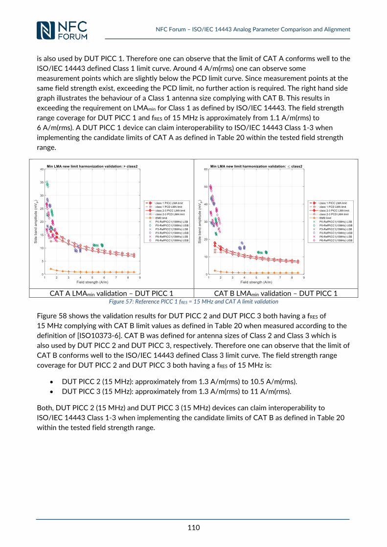
NFC Forum – ISO/IEC 14443 Analog Parameter Comparison and Alignment
110
is also used by DUT PICC 1. Therefore one can observe that the limit of CAT A conforms well to the
ISO/IEC 14443 defined Class 1 limit curve. Around 4 A/m(rms) one can observe some
measurement points which are slightly below the PCD limit curve. Since measurement points at the
same field strength exist, exceeding the PCD limit, no further action is required. The right hand side
graph illustrates the behaviour of a Class 1 antenna size complying with CAT B. This results in
exceeding the requirement on LMAmin for Class 1 as defined by ISO/IEC 14443. The field strength
range coverage for DUT PICC 1 and fRES of 15 MHz is approximately from 1.1 A/m(rms) to
6 A/m(rms). A DUT PICC 1 device can claim interoperability to ISO/IEC 14443 Class 1-3 when
implementing the candidate limits of CAT A as defined in Table 20 within the tested field strength
range.
CAT A LMAmin validation – DUT PICC 1 CAT B LMAmin validation – DUT PICC 1
Figure 57: Reference PICC 1 fRES = 15 MHz and CAT A limit validation
Figure 58 shows the validation results for DUT PICC 2 and DUT PICC 3 both having a fRES of
15 MHz complying with CAT B limit values as defined in Table 20 when measured according to the
definition of [ISO10373-6]. CAT B was defined for antenna sizes of Class 2 and Class 3 which is
also used by DUT PICC 2 and DUT PICC 3, respectively. Therefore one can observe that the limit of
CAT B conforms well to the ISO/IEC 14443 defined Class 3 limit curve. The field strength range
coverage for DUT PICC 2 and DUT PICC 3 both having a fRES of 15 MHz is:
DUT PICC 2 (15 MHz): approximately from 1.3 A/m(rms) to 10.5 A/m(rms).
DUT PICC 3 (15 MHz): approximately from 1.3 A/m(rms) to 11 A/m(rms).
Both, DUT PICC 2 (15 MHz) and DUT PICC 3 (15 MHz) devices can claim interoperability to
ISO/IEC 14443 Class 1-3 when implementing the candidate limits of CAT B as defined in Table 20
within the tested field strength range.
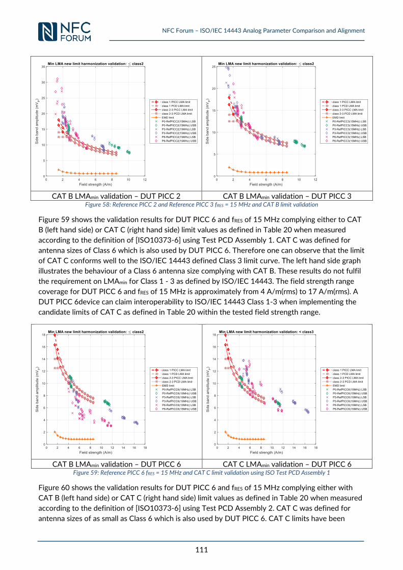
NFC Forum – ISO/IEC 14443 Analog Parameter Comparison and Alignment
111
CAT B LMAmin validation – DUT PICC 2 CAT B LMAmin validation – DUT PICC 3
Figure 58: Reference PICC 2 and Reference PICC 3 fRES = 15 MHz and CAT B limit validation
Figure 59 shows the validation results for DUT PICC 6 and fRES of 15 MHz complying either to CAT
B (left hand side) or CAT C (right hand side) limit values as defined in Table 20 when measured
according to the definition of [ISO10373-6] using Test PCD Assembly 1. CAT C was defined for
antenna sizes of Class 6 which is also used by DUT PICC 6. Therefore one can observe that the limit
of CAT C conforms well to the ISO/IEC 14443 defined Class 3 limit curve. The left hand side graph
illustrates the behaviour of a Class 6 antenna size complying with CAT B. These results do not fulfil
the requirement on LMAmin for Class 1 - 3 as defined by ISO/IEC 14443. The field strength range
coverage for DUT PICC 6 and fRES of 15 MHz is approximately from 4 A/m(rms) to 17 A/m(rms). A
DUT PICC 6device can claim interoperability to ISO/IEC 14443 Class 1-3 when implementing the
candidate limits of CAT C as defined in Table 20 within the tested field strength range.
CAT B LMAmin validation – DUT PICC 6 CAT C LMAmin validation – DUT PICC 6
Figure 59: Reference PICC 6 fRES = 15 MHz and CAT C limit validation using ISO Test PCD Assembly 1
Figure 60 shows the validation results for DUT PICC 6 and fRES of 15 MHz complying either with
CAT B (left hand side) or CAT C (right hand side) limit values as defined in Table 20 when measured
according to the definition of [ISO10373-6] using Test PCD Assembly 2. CAT C was defined for
antenna sizes of as small as Class 6 which is also used by DUT PICC 6. CAT C limits have been
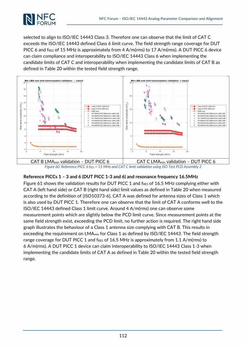
NFC Forum – ISO/IEC 14443 Analog Parameter Comparison and Alignment
112
selected to align to ISO/IEC 14443 Class 3. Therefore one can observe that the limit of CAT C
exceeds the ISO/IEC 14443 defined Class 6 limit curve. The field strength range coverage for DUT
PICC 6 and fRES of 15 MHz is approximately from 4 A/m(rms) to 17 A/m(rms). A DUT PICC 6 device
can claim compliance and interoperability to ISO/IEC 14443 Class 6 when implementing the
candidate limits of CAT C and interoperability when implementing the candidate limits of CAT B as
defined in Table 20 within the tested field strength range.
CAT B LMAmin validation – DUT PICC 6 CAT C LMAmin validation – DUT PICC 6
Figure 60: Reference PICC 6 fRES = 15 MHz and CAT C limit validation using ISO Test PCD Assembly 2
Reference PICCs 1 – 3 and 6 (DUT PICC 1-3 and 6) and resonance frequency 16.5MHz
Figure 61 shows the validation results for DUT PICC 1 and fRES of 16.5 MHz complying either with
CAT A (left hand side) or CAT B (right hand side) limit values as defined in Table 20 when measured
according to the definition of [ISO10373-6]. CAT A was defined for antenna sizes of Class 1 which
is also used by DUT PICC 1. Therefore one can observe that the limit of CAT A conforms well to the
ISO/IEC 14443 defined Class 1 limit curve. Around 4 A/m(rms) one can observe some
measurement points which are slightly below the PCD limit curve. Since measurement points at the
same field strength exist, exceeding the PCD limit, no further action is required. The right hand side
graph illustrates the behaviour of a Class 1 antenna size complying with CAT B. This results in
exceeding the requirement on LMAmin for Class 1 as defined by ISO/IEC 14443. The field strength
range coverage for DUT PICC 1 and fRES of 16.5 MHz is approximately from 1.1 A/m(rms) to
6 A/m(rms). A DUT PICC 1 device can claim interoperability to ISO/IEC 14443 Class 1-3 when
implementing the candidate limits of CAT A as defined in Table 20 within the tested field strength
range.
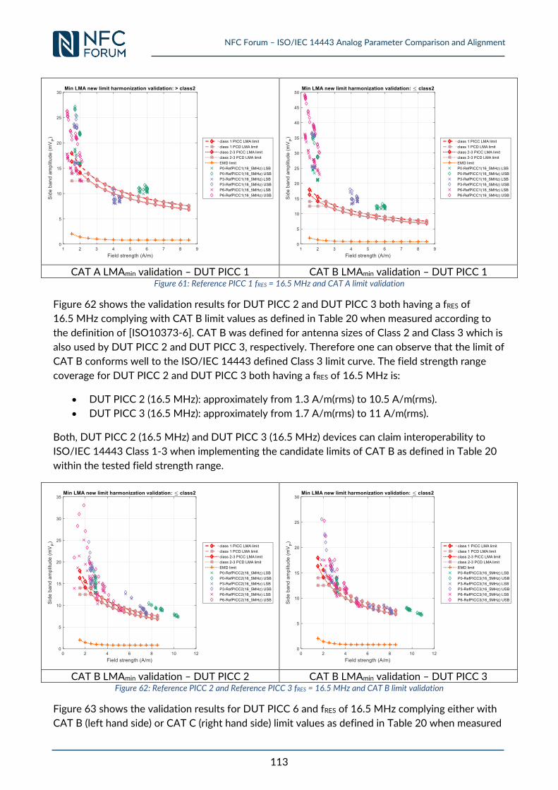
NFC Forum – ISO/IEC 14443 Analog Parameter Comparison and Alignment
113
CAT A LMAmin validation – DUT PICC 1 CAT B LMAmin validation – DUT PICC 1
Figure 61: Reference PICC 1 fRES = 16.5 MHz and CAT A limit validation
Figure 62 shows the validation results for DUT PICC 2 and DUT PICC 3 both having a fRES of
16.5 MHz complying with CAT B limit values as defined in Table 20 when measured according to
the definition of [ISO10373-6]. CAT B was defined for antenna sizes of Class 2 and Class 3 which is
also used by DUT PICC 2 and DUT PICC 3, respectively. Therefore one can observe that the limit of
CAT B conforms well to the ISO/IEC 14443 defined Class 3 limit curve. The field strength range
coverage for DUT PICC 2 and DUT PICC 3 both having a fRES of 16.5 MHz is:
DUT PICC 2 (16.5 MHz): approximately from 1.3 A/m(rms) to 10.5 A/m(rms).
DUT PICC 3 (16.5 MHz): approximately from 1.7 A/m(rms) to 11 A/m(rms).
Both, DUT PICC 2 (16.5 MHz) and DUT PICC 3 (16.5 MHz) devices can claim interoperability to
ISO/IEC 14443 Class 1-3 when implementing the candidate limits of CAT B as defined in Table 20
within the tested field strength range.
CAT B LMAmin validation – DUT PICC 2 CAT B LMAmin validation – DUT PICC 3
Figure 62: Reference PICC 2 and Reference PICC 3 fRES = 16.5 MHz and CAT B limit validation
Figure 63 shows the validation results for DUT PICC 6 and fRES of 16.5 MHz complying either with
CAT B (left hand side) or CAT C (right hand side) limit values as defined in Table 20 when measured
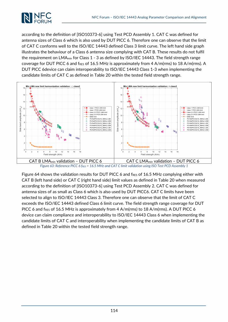
NFC Forum – ISO/IEC 14443 Analog Parameter Comparison and Alignment
114
according to the definition of [ISO10373-6] using Test PCD Assembly 1. CAT C was defined for
antenna sizes of Class 6 which is also used by DUT PICC 6. Therefore one can observe that the limit
of CAT C conforms well to the ISO/IEC 14443 defined Class 3 limit curve. The left hand side graph
illustrates the behaviour of a Class 6 antenna size complying with CAT B. These results do not fulfil
the requirement on LMAmin for Class 1 - 3 as defined by ISO/IEC 14443. The field strength range
coverage for DUT PICC 6 and fRES of 16.5 MHz is approximately from 4 A/m(rms) to 18 A/m(rms). A
DUT PICC 6device can claim interoperability to ISO/IEC 14443 Class 1-3 when implementing the
candidate limits of CAT C as defined in Table 20 within the tested field strength range.
CAT B LMAmin validation – DUT PICC 6 CAT C LMAmin validation – DUT PICC 6
Figure 63: Reference PICC 6 fRES = 16.5 MHz and CAT C limit validation using ISO Test PCD Assembly 1
Figure 64 shows the validation results for DUT PICC 6 and fRES of 16.5 MHz complying either with
CAT B (left hand side) or CAT C (right hand side) limit values as defined in Table 20 when measured
according to the definition of [ISO10373-6] using Test PCD Assembly 2. CAT C was defined for
antenna sizes of as small as Class 6 which is also used by DUT PICC6. CAT C limits have been
selected to align to ISO/IEC 14443 Class 3. Therefore one can observe that the limit of CAT C
exceeds the ISO/IEC 14443 defined Class 6 limit curve. The field strength range coverage for DUT
PICC 6 and fRES of 16.5 MHz is approximately from 4 A/m(rms) to 18 A/m(rms). A DUT PICC 6
device can claim compliance and interoperability to ISO/IEC 14443 Class 6 when implementing the
candidate limits of CAT C and interoperability when implementing the candidate limits of CAT B as
defined in Table 20 within the tested field strength range.
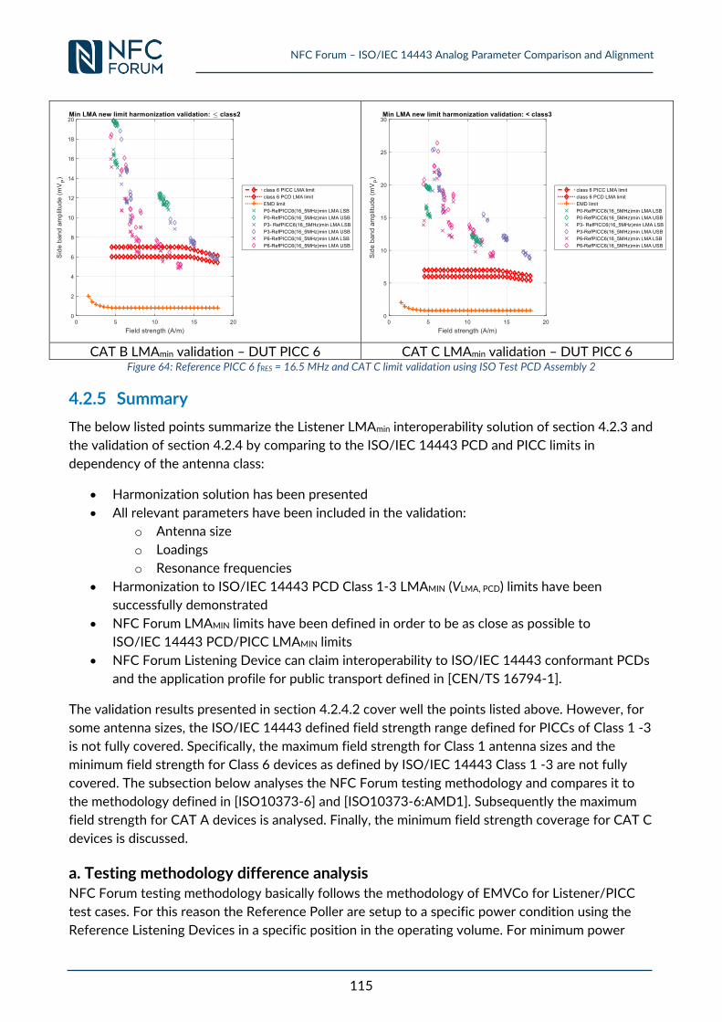
NFC Forum – ISO/IEC 14443 Analog Parameter Comparison and Alignment
115
CAT B LMAmin validation – DUT PICC 6 CAT C LMAmin validation – DUT PICC 6
Figure 64: Reference PICC 6 fRES = 16.5 MHz and CAT C limit validation using ISO Test PCD Assembly 2
4.2.5 Summary
The below listed points summarize the Listener LMAmin interoperability solution of section 4.2.3 and
the validation of section 4.2.4 by comparing to the ISO/IEC 14443 PCD and PICC limits in
dependency of the antenna class:
Harmonization solution has been presented
All relevant parameters have been included in the validation:
o Antenna size
o Loadings
o Resonance frequencies
Harmonization to ISO/IEC 14443 PCD Class 1-3 LMAMIN (VLMA, PCD) limits have been
successfully demonstrated
NFC Forum LMAMIN limits have been defined in order to be as close as possible to
ISO/IEC 14443 PCD/PICC LMAMIN limits
NFC Forum Listening Device can claim interoperability to ISO/IEC 14443 conformant PCDs
and the application profile for public transport defined in [CEN/TS 16794-1].
The validation results presented in section 4.2.4.2 cover well the points listed above. However, for
some antenna sizes, the ISO/IEC 14443 defined field strength range defined for PICCs of Class 1 -3
is not fully covered. Specifically, the maximum field strength for Class 1 antenna sizes and the
minimum field strength for Class 6 devices as defined by ISO/IEC 14443 Class 1 -3 are not fully
covered. The subsection below analyses the NFC Forum testing methodology and compares it to
the methodology defined in [ISO10373-6] and [ISO10373-6:AMD1]. Subsequently the maximum
field strength for CAT A devices is analysed. Finally, the minimum field strength coverage for CAT C
devices is discussed.
a. Testing methodology difference analysis NFC Forum testing methodology basically follows the methodology of EMVCo for Listener/PICC
test cases. For this reason the Reference Poller are setup to a specific power condition using the
Reference Listening Devices in a specific position in the operating volume. For minimum power
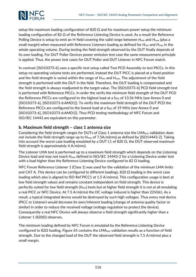
NFC Forum – ISO/IEC 14443 Analog Parameter Comparison and Alignment
116
setup the maximum loading configuration of 820 Ω and for maximum power setup the minimum
loading configuration of 82 Ω of the Reference Listening Device is used. As a result the Reference
Polling Device is setup to emit an H-field covering the valid range between Hmin and Hmax (plus a
small margin) when measured with Reference Listeners loading as defined for Hmin and Hmax in the
whole operating volume. During testing the field strength observed by the DUT finally depends of
its own loading. For DUT Poller Devices power emission test case the same measurement principle
is applied. Thus, the power test cases for DUT Poller and DUT Listener in NFC Forum match.
In contrast [ISO10373-6] uses a specific test setup called Test PCD Assembly to test PICCs. In this
setup no operating volume tests are performed, instead the DUT PICC is placed at a fixed position
and the field strength is varied within the range of Hmin and Hmax. The adjustment of the field
strength is performed with the DUT in the field. Therefore, the DUT loading is compensated and
the field strength is always readjusted to the target value. The [ISO10373-6] PCD field strength test
is performed with Reference PICCs. In order the verify the minimum field strength of the DUT PCD
the Reference PICCs are configured to the highest load at a fRES of 13.56 MHz (see Annex 0 and
[ISO10373-6], [ISO10373-6:AMD1]). To verify the maximum field strength of the DUT PCD the
Reference PICCs are configured to the lowest load at a fRES of 19 MHz (see Annex 0 and
[ISO10373-6], [ISO10373-6:AMD1]). Thus PCD testing methodology of NFC Forum and
ISO/IEC 14443 are equivalent on this parameter.
b. Maximum field strength – class 1 antenna size Considering the field strength ranges for DUTs of Class 1 antenna size the LMAmin validation does not include the field strength range up to Hmax of 7.5A/m(rms) as defined by [ISO14443-2]. Taking into account the worst case loading emulated by a DUT L1 of 820 Ω, the DUT observed maximum field strength is approximately 4 A/m(rms).
The Listener LMA test is performed up to a maximum field strength which depends on the Listening Device load and may not reach Hmax defined in ISO/IEC 14443-2 for a Listening Device under test with a load higher than the Reference Listening Device configured to 82 Ω loading.
NFC Forum Reference Listener 1 (Class 1) was used for the validation of the minimum LMA limits
and CAT A. This device can be configured to different loadings. 820 Ω loading is the worst case
loading which also is aligned to ISO Ref PICC1 at 1.5 A/m(rms). This configuration usage is best at
low field strength values and remains constant independent on field strength. This device is
perfectly suited for low field strength (Hmin) tests but at higher field strength it is not at all emulating
a real PICC or NFC Device. At 7.5 A/m(rms) the DC voltage induced is higher than 22V(dc). As a
result, a typical integrated device would be destroyed by such high voltages. Thus every real device
(PICC or Listener) would decrease its own/inherent loading (change of antenna quality factor or
similar) in order to reduce the received voltage (voltage regulation to protect the device).
Consequently a real NFC Device will always observe a field strength significantly higher than a
Listener 1 (820Ω) observes.
The minimum loading defined by NFC Forum is emulated by the Reference Listening Device
configured to 82Ω loading. Figure 65 contains the LMAmin validation results as a function of field
strength. Due to the changed load of the DUT the observed field strength is 7.5 A/m(rms) plus a
small margin.
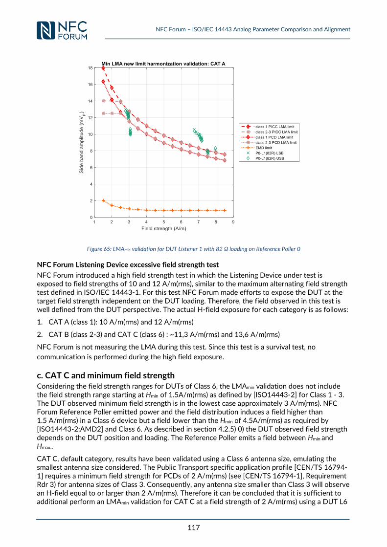
NFC Forum – ISO/IEC 14443 Analog Parameter Comparison and Alignment
117
Figure 65: LMAmin validation for DUT Listener 1 with 82 Ω loading on Reference Poller 0
NFC Forum Listening Device excessive field strength test
NFC Forum introduced a high field strength test in which the Listening Device under test is exposed to field strengths of 10 and 12 A/m(rms), similar to the maximum alternating field strength test defined in ISO/IEC 14443-1. For this test NFC Forum made efforts to expose the DUT at the target field strength independent on the DUT loading. Therefore, the field observed in this test is well defined from the DUT perspective. The actual H-field exposure for each category is as follows:
1. CAT A (class 1): 10 A/m(rms) and 12 A/m(rms)
2. CAT B (class 2-3) and CAT C (class 6) : ~11,3 A/m(rms) and 13,6 A/m(rms)
NFC Forum is not measuring the LMA during this test. Since this test is a survival test, no
communication is performed during the high field exposure.
c. CAT C and minimum field strength Considering the field strength ranges for DUTs of Class 6, the LMAmin validation does not include the field strength range starting at Hmin of 1.5A/m(rms) as defined by [ISO14443-2] for Class 1 - 3. The DUT observed minimum field strength is in the lowest case approximately 3 A/m(rms). NFC Forum Reference Poller emitted power and the field distribution induces a field higher than 1.5 A/m(rms) in a Class 6 device but a field lower than the Hmin of 4.5A/m(rms) as required by [ISO14443-2:AMD2] and Class 6. As described in section 4.2.5) 0) the DUT observed field strength depends on the DUT position and loading. The Reference Poller emits a field between Hmin and Hmax..
CAT C, default category, results have been validated using a Class 6 antenna size, emulating the smallest antenna size considered. The Public Transport specific application profile [CEN/TS 16794-1] requires a minimum field strength for PCDs of 2 A/m(rms) (see [CEN/TS 16794-1], Requirement Rdr 3) for antenna sizes of Class 3. Consequently, any antenna size smaller than Class 3 will observe an H-field equal to or larger than 2 A/m(rms). Therefore it can be concluded that it is sufficient to additional perform an LMAmin validation for CAT C at a field strength of 2 A/m(rms) using a DUT L6
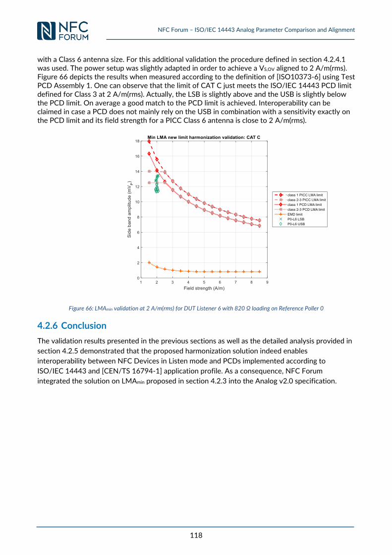
NFC Forum – ISO/IEC 14443 Analog Parameter Comparison and Alignment
118
with a Class 6 antenna size. For this additional validation the procedure defined in section 4.2.4.1 was used. The power setup was slightly adapted in order to achieve a VS,OV aligned to 2 A/m(rms). Figure 66 depicts the results when measured according to the definition of [ISO10373-6] using Test PCD Assembly 1. One can observe that the limit of CAT C just meets the ISO/IEC 14443 PCD limit defined for Class 3 at 2 A/m(rms). Actually, the LSB is slightly above and the USB is slightly below the PCD limit. On average a good match to the PCD limit is achieved. Interoperability can be claimed in case a PCD does not mainly rely on the USB in combination with a sensitivity exactly on the PCD limit and its field strength for a PICC Class 6 antenna is close to 2 A/m(rms).
Figure 66: LMAmin validation at 2 A/m(rms) for DUT Listener 6 with 820 Ω loading on Reference Poller 0
4.2.6 Conclusion
The validation results presented in the previous sections as well as the detailed analysis provided in
section 4.2.5 demonstrated that the proposed harmonization solution indeed enables
interoperability between NFC Devices in Listen mode and PCDs implemented according to
ISO/IEC 14443 and [CEN/TS 16794-1] application profile. As a consequence, NFC Forum
integrated the solution on LMAmin proposed in section 4.2.3 into the Analog v2.0 specification.
NFC Forum – ISO/IEC 14443 Analog Parameter Comparison and Alignment
119
5 Electromagnetic Disturbance (EMD) Electromagnetic disturbances (EMD) occurring in the frequency band of communication can impact
the Card to Reader communication stability. In order to mitigate the risk of communication
instabilities due to EMD, ISO/IEC 14443, EMVCo and NFC Forum defined requirements on EMD.
The below points compare the EMD requirements as defined by each standardization body for
Poller/PCD and Listener/PICC:
Poller EMD handling rules of NFC Forum [NFC_DIGITAL] are aligned with
[EMVCo_Book_D_v2_4] and [ISO14443-3:AMD1] PCD EMD requirements.
Timing requirements regarding EMD for Poller/PCD are aligned between NFC Forum
[NFC_DIGITAL] and [EMVCo_Book_D_v2_4] and are similar to [ISO14443-3:AMD1].
Timing requirements regarding EMD for Listener/PICC are aligned between [NFC_DIGITAL],
[EMVCo_Book_D_v2_4] and [ISO14443-3:AMD1].
Analog PCD and PICC EMD requirements defined in ISO/IEC 14443 are not defined by
both, NFC Forum and EMVCo.
Section 5.1 evaluates the impact of the analog EMD requirement on interoperability for NFC
Forum.
5.1 EMD Impact Analysis
This section performs an analysis on the benefits for NFC Forum to introduce analog EMD
requirements. The benefits are assessed in terms of an interoperability analysis between NFC
Forum Devices and the communication to legacy infrastructure and PICCs. Firstly, the NFC Forum
Device in Poll or Reader role and afterwards the NFC Forum Device in Listen or CE role are
analysed.
NFC Forum Device in Poll or Reader role:
o Communication with an ISO-conformant PICC should be supported.
o PICC dynamic current consumption during command execution may result in
arbitrary load changes. This load change affects the magnetic field.
o Conclusion: For NFC Forum Devices in Poll or Reader role, Analog EMD is required.
NFC Forum Device in Listen or CE role:
o An NFC Forum Device is battery powered therefore no load change will affect the
magnetic field.
o No EMD due to command execution and/or crypto processing
o Conclusion: For NFC Forum Devices in Listen or CE role, Analog EMD requirement
is rated as low priority.
Based on the provided analysis NFC Forum will consider to introduce requirements and test cases
for the analog EMD parameter and for NFC Forum Polling Devices in a future version of the Analog
Specification and according test cases document.
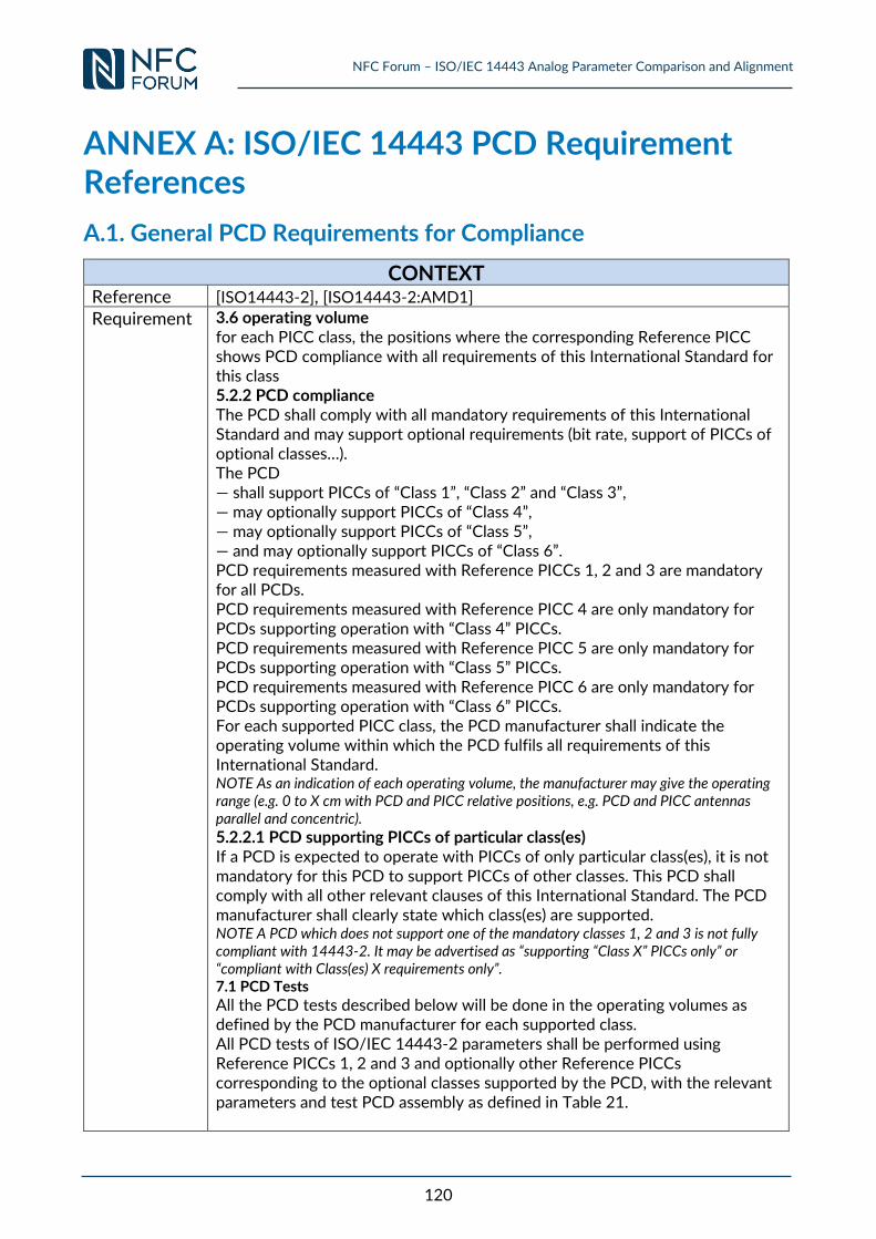
NFC Forum – ISO/IEC 14443 Analog Parameter Comparison and Alignment
120
ANNEX A: ISO/IEC 14443 PCD Requirement References
A.1. General PCD Requirements for Compliance
CONTEXT Reference [ISO14443-2], [ISO14443-2:AMD1] Requirement 3.6 operating volume
for each PICC class, the positions where the corresponding Reference PICC shows PCD compliance with all requirements of this International Standard for this class 5.2.2 PCD compliance The PCD shall comply with all mandatory requirements of this International Standard and may support optional requirements (bit rate, support of PICCs of optional classes…). The PCD — shall support PICCs of “Class 1”, “Class 2” and “Class 3”, — may optionally support PICCs of “Class 4”, — may optionally support PICCs of “Class 5”, — and may optionally support PICCs of “Class 6”. PCD requirements measured with Reference PICCs 1, 2 and 3 are mandatory for all PCDs. PCD requirements measured with Reference PICC 4 are only mandatory for PCDs supporting operation with “Class 4” PICCs. PCD requirements measured with Reference PICC 5 are only mandatory for PCDs supporting operation with “Class 5” PICCs. PCD requirements measured with Reference PICC 6 are only mandatory for PCDs supporting operation with “Class 6” PICCs. For each supported PICC class, the PCD manufacturer shall indicate the operating volume within which the PCD fulfils all requirements of this International Standard. NOTE As an indication of each operating volume, the manufacturer may give the operating range (e.g. 0 to X cm with PCD and PICC relative positions, e.g. PCD and PICC antennas parallel and concentric).
5.2.2.1 PCD supporting PICCs of particular class(es) If a PCD is expected to operate with PICCs of only particular class(es), it is not mandatory for this PCD to support PICCs of other classes. This PCD shall comply with all other relevant clauses of this International Standard. The PCD manufacturer shall clearly state which class(es) are supported. NOTE A PCD which does not support one of the mandatory classes 1, 2 and 3 is not fully compliant with 14443-2. It may be advertised as “supporting “Class X” PICCs only” or “compliant with Class(es) X requirements only”. 7.1 PCD Tests
All the PCD tests described below will be done in the operating volumes as defined by the PCD manufacturer for each supported class. All PCD tests of ISO/IEC 14443-2 parameters shall be performed using Reference PICCs 1, 2 and 3 and optionally other Reference PICCs corresponding to the optional classes supported by the PCD, with the relevant parameters and test PCD assembly as defined in Table 21.
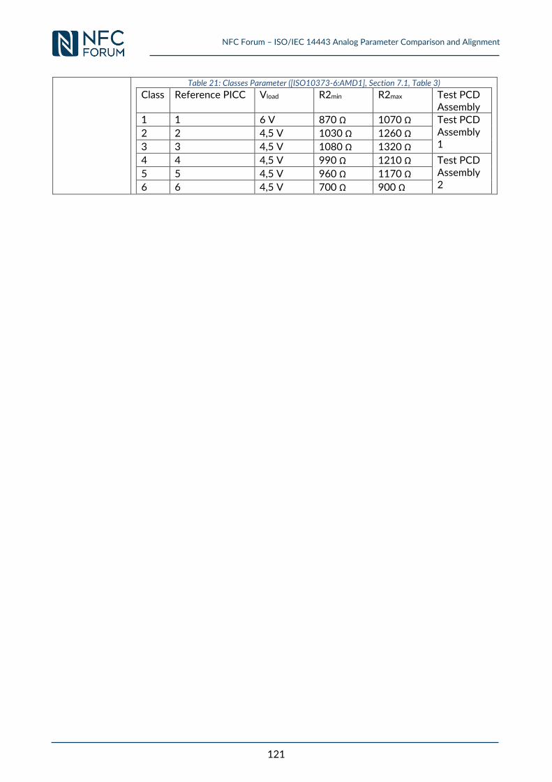
NFC Forum – ISO/IEC 14443 Analog Parameter Comparison and Alignment
121
Table 21: Classes Parameter ([ISO10373-6:AMD1], Section 7.1, Table 3)
Class Reference PICC Vload R2min R2max Test PCD Assembly
1 1 6 V 870 Ω 1070 Ω Test PCD Assembly 1
2 2 4,5 V 1030 Ω 1260 Ω
3 3 4,5 V 1080 Ω 1320 Ω
4 4 4,5 V 990 Ω 1210 Ω Test PCD Assembly 2
5 5 4,5 V 960 Ω 1170 Ω
6 6 4,5 V 700 Ω 900 Ω
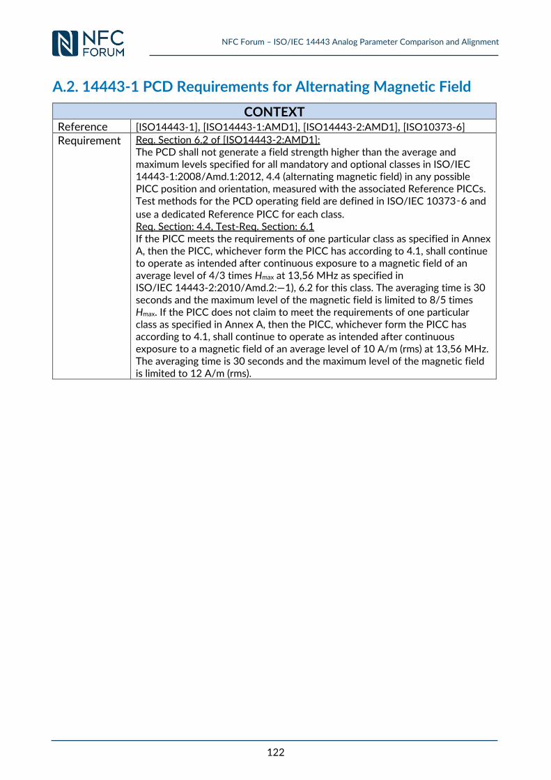
NFC Forum – ISO/IEC 14443 Analog Parameter Comparison and Alignment
122
A.2. 14443-1 PCD Requirements for Alternating Magnetic Field
CONTEXT Reference [ISO14443-1], [ISO14443-1:AMD1], [ISO14443-2:AMD1], [ISO10373-6] Requirement Req. Section 6.2 of [ISO14443-2:AMD1]:
The PCD shall not generate a field strength higher than the average and maximum levels specified for all mandatory and optional classes in ISO/IEC 14443-1:2008/Amd.1:2012, 4.4 (alternating magnetic field) in any possible PICC position and orientation, measured with the associated Reference PICCs. Test methods for the PCD operating field are defined in ISO/IEC 10373‑6 and
use a dedicated Reference PICC for each class. Req. Section: 4.4, Test-Req. Section: 6.1 If the PICC meets the requirements of one particular class as specified in Annex A, then the PICC, whichever form the PICC has according to 4.1, shall continue to operate as intended after continuous exposure to a magnetic field of an average level of 4/3 times Hmax at 13,56 MHz as specified in ISO/IEC 14443-2:2010/Amd.2:—1), 6.2 for this class. The averaging time is 30 seconds and the maximum level of the magnetic field is limited to 8/5 times Hmax. If the PICC does not claim to meet the requirements of one particular class as specified in Annex A, then the PICC, whichever form the PICC has according to 4.1, shall continue to operate as intended after continuous exposure to a magnetic field of an average level of 10 A/m (rms) at 13,56 MHz. The averaging time is 30 seconds and the maximum level of the magnetic field is limited to 12 A/m (rms).
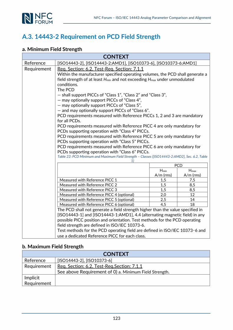
NFC Forum – ISO/IEC 14443 Analog Parameter Comparison and Alignment
123
A.3. 14443-2 Requirement on PCD Field Strength
a. Minimum Field Strength
CONTEXT Reference [ISO14443-2], [ISO14443-2:AMD1], [ISO10373-6], [ISO10373-6:AMD1] Requirement Req. Section: 6.2, Test-Req. Section: 7.1.1
Within the manufacturer specified operating volumes, the PCD shall generate a field strength of at least Hmin and not exceeding Hmax under unmodulated conditions. The PCD — shall support PICCs of “Class 1”, “Class 2” and “Class 3”, — may optionally support PICCs of “Class 4”, — may optionally support PICCs of “Class 5”, — and may optionally support PICCs of “Class 6”. PCD requirements measured with Reference PICCs 1, 2 and 3 are mandatory for all PCDs. PCD requirements measured with Reference PICC 4 are only mandatory for PCDs supporting operation with “Class 4” PICCs. PCD requirements measured with Reference PICC 5 are only mandatory for PCDs supporting operation with “Class 5” PICCs. PCD requirements measured with Reference PICC 6 are only mandatory for PCDs supporting operation with “Class 6” PICCs. Table 22: PCD Minimum and Maximum Field Strength – Classes ([ISO14443-2:AMD2], Sec. 6.2, Table
1)
PCD Hmin
A/m (rms) Hmax
A/m (rms) Measured with Reference PICC 1 1,5 7,5
Measured with Reference PICC 2 1,5 8,5 Measured with Reference PICC 3 1,5 8,5 Measured with Reference PICC 4 (optional) 2,0 12
Measured with Reference PICC 5 (optional) 2,5 14 Measured with Reference PICC 6 (optional) 4,5 18
The PCD shall not generate a field strength higher than the value specified in [ISO14443-1] and [ISO14443-1:AMD1], 4.4 (alternating magnetic field) in any possible PICC position and orientation. Test methods for the PCD operating field strength are defined in ISO/IEC 10373-6. Test methods for the PCD operating field are defined in ISO/IEC 10373‑6 and
use a dedicated Reference PICC for each class.
b. Maximum Field Strength
CONTEXT Reference [ISO14443-2], [ISO10373-6] Requirement Req. Section: 6.2, Test-Req.Section: 7.1.1
See above Requirement of 0) a. Minimum Field Strength. Implicit Requirement
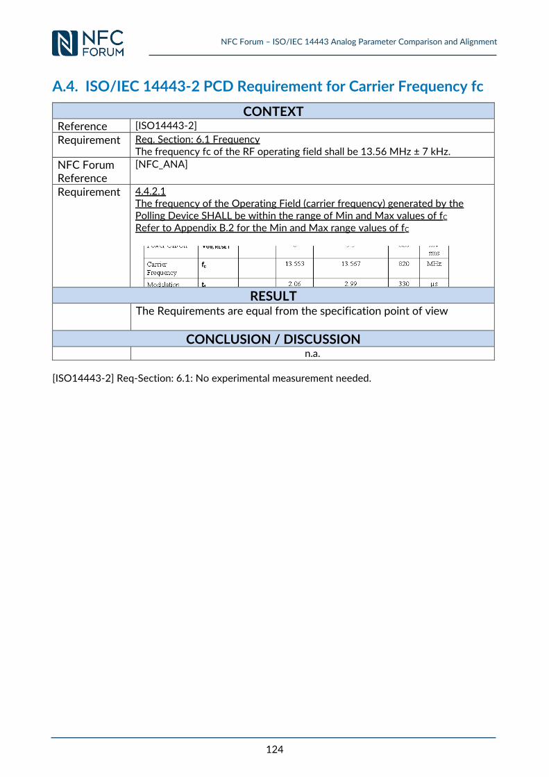
NFC Forum – ISO/IEC 14443 Analog Parameter Comparison and Alignment
124
A.4. ISO/IEC 14443-2 PCD Requirement for Carrier Frequency fc
CONTEXT Reference [ISO14443-2]
Requirement Req. Section: 6.1 Frequency The frequency fc of the RF operating field shall be 13.56 MHz ± 7 kHz.
NFC Forum Reference
[NFC_ANA]
Requirement 4.4.2.1 The frequency of the Operating Field (carrier frequency) generated by the Polling Device SHALL be within the range of Min and Max values of fC Refer to Appendix B.2 for the Min and Max range values of fC
RESULT
The Requirements are equal from the specification point of view
CONCLUSION / DISCUSSION
n.a.
[ISO14443-2] Req-Section: 6.1: No experimental measurement needed.
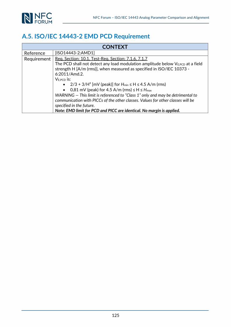
NFC Forum – ISO/IEC 14443 Analog Parameter Comparison and Alignment
125
A.5. ISO/IEC 14443-2 EMD PCD Requirement
CONTEXT
Reference [ISO14443-2:AMD1]
Requirement Req. Section: 10.1, Test-Req. Section: 7.1.6, 7.1.7 The PCD shall not detect any load modulation amplitude below VE,PCD at a field strength H [A/m (rms)], when measured as specified in ISO/IEC 10373 -6:2011/Amd.2. VE,PCD is:
2/3 + 3/H² [mV (peak)] for Hmin ≤ H ≤ 4.5 A/m (rms)
0,81 mV (peak) for 4.5 A/m (rms) ≤ H ≤ Hmax
WARNING — This limit is referenced to “Class 1” only and may be detrimental to communication with PICCs of the other classes. Values for other classes will be specified in the future. Note: EMD limit for PCD and PICC are identical. No margin is applied.
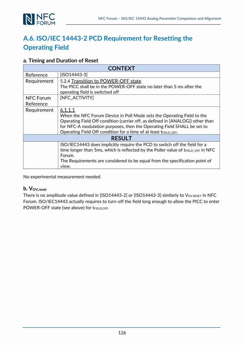
NFC Forum – ISO/IEC 14443 Analog Parameter Comparison and Alignment
126
A.6. ISO/IEC 14443-2 PCD Requirement for Resetting the
Operating Field
a. Timing and Duration of Reset
CONTEXT Reference [ISO14443-3]
Requirement 5.2.4 Transition to POWER-OFF state The PICC shall be in the POWER-OFF state no later than 5 ms after the operating field is switched off
NFC Forum Reference
[NFC_ACTIVITY]
Requirement 6.1.1.1 When the NFC Forum Device in Poll Mode sets the Operating Field to the Operating Field Off condition (carrier off, as defined in [ANALOG]) other than for NFC-A modulation purposes, then the Operating Field SHALL be set to Operating Field Off condition for a time of at least tFIELD_OFF.
RESULT
ISO/IEC14443 does implicitly require the PCD to switch off the field for a time longer than 5ms, which is reflected by the Poller value of tFIELD_OFF in NFC Forum. The Requirements are considered to be equal from the specification point of view.
No experimental measurement needed.
b. VOV,reset There is no amplitude value defined in [ISO14443-2] or [ISO14443-3] similarly to VOV,RESET in NFC
Forum. ISO/IEC14443 actually requires to turn-off the field long enough to allow the PICC to enter
POWER-OFF state (see above) for tFIELD,OFF.
NFC Forum – ISO/IEC 14443 Analog Parameter Comparison and Alignment
127
A.7. ISO/IEC 14443-2 PCD Requirements for Power-off of the
Operating Field
No Requirement available.
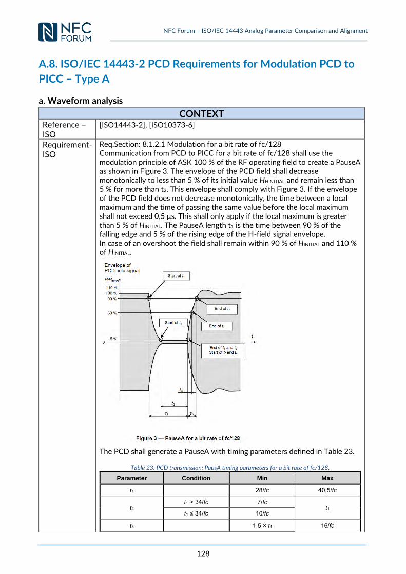
NFC Forum – ISO/IEC 14443 Analog Parameter Comparison and Alignment
128
A.8. ISO/IEC 14443-2 PCD Requirements for Modulation PCD to
PICC – Type A
a. Waveform analysis
CONTEXT
Reference – ISO
[ISO14443-2], [ISO10373-6]
Requirement- ISO
Req.Section: 8.1.2.1 Modulation for a bit rate of fc/128 Communication from PCD to PICC for a bit rate of fc/128 shall use the modulation principle of ASK 100 % of the RF operating field to create a PauseA as shown in Figure 3. The envelope of the PCD field shall decrease monotonically to less than 5 % of its initial value HHINITIAL and remain less than 5 % for more than t2. This envelope shall comply with Figure 3. If the envelope of the PCD field does not decrease monotonically, the time between a local maximum and the time of passing the same value before the local maximum shall not exceed 0,5 μs. This shall only apply if the local maximum is greater than 5 % of HINITIAL. The PauseA length t1 is the time between 90 % of the falling edge and 5 % of the rising edge of the H-field signal envelope. In case of an overshoot the field shall remain within 90 % of HINITIAL and 110 % of HINITIAL.
The PCD shall generate a PauseA with timing parameters defined in Table 23.
Table 23: PCD transmission: PausA timing parameters for a bit rate of fc/128.
Parameter Condition Min Max
t1 28/fc 40,5/fc
t2 t1 > 34/fc 7/fc
t1 t1 ≤ 34/fc 10/fc
t3 1,5 × t4 16/fc
NFC Forum – ISO/IEC 14443 Analog Parameter Comparison and Alignment
129
t4 0 6/fc
NOTE 1 PCD implementations may be restricted to generate a PauseA with values of t1 = n/fc (n = integer). Therefore measurement of t1 should be rounded to the closest n in the unit 1/fc. NOTE 2 The maximum value of t2 is a function of the measured value of t1. NOTE 3 The minimum value of t3 is a function of the measured value of t4. For a bit rate of fc/128 the PCD shall generate a PauseA with a rise time t3 ⎯ greater than both 0/fc and (t1 – t2) – 24.5/fc, ⎯ and less than both (t1 – t2) + 7/fc and 16/fc.
b. Overshoot and Undershoot analysis
CONTEXT
Reference [ISO14443-2]
Requirement Req.Section: 8.1.2.1 Modulation for a bit rate of fc/128 In case of an overshoot the field shall remain within 90 % of HINITIAL and 110 % of HINITIAL. Maximum of overshoots: OSmax = 10%
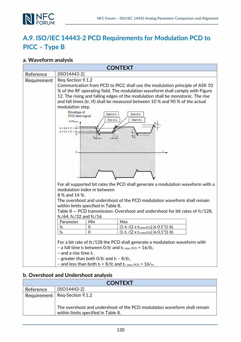
NFC Forum – ISO/IEC 14443 Analog Parameter Comparison and Alignment
130
A.9. ISO/IEC 14443-2 PCD Requirements for Modulation PCD to
PICC – Type B
a. Waveform analysis
CONTEXT
Reference [ISO14443-2]
Requirement Req-Section 9.1.2 Communication from PCD to PICC shall use the modulation principle of ASK 10 % of the RF operating field. The modulation waveform shall comply with Figure 12. The rising and falling edges of the modulation shall be monotonic. The rise and fall times (tr, tf) shall be measured between 10 % and 90 % of the actual modulation step.
For all supported bit rates the PCD shall generate a modulation waveform with a modulation index m between 8 % and 14 %. The overshoot and undershoot of the PCD modulation waveform shall remain within limits specified in Table 8. Table 8 — PCD transmission: Overshoot and undershoot for bit rates of fc/128, fc/64, fc/32 and fc/16
Parameter Min Max hf 0 (1-tf /(2 x tf,max,PCD) )x 0.1*(1-b)
hr 0 (1-tr /(2 x tr,max,PCD) )x 0.1*(1-b)
For a bit rate of fc/128 the PCD shall generate a modulation waveform with ⎯ a fall time tf between 0/fc and tf, max, PCD = 16/fc, ⎯ and a rise time tr ⎯ greater than both 0/fc and tf – 8/fc, ⎯ and less than both tf + 8/fc and tr, max, PCD = 16/fc.
b. Overshoot and Undershoot analysis
CONTEXT
Reference [ISO14443-2]
Requirement Req-Section 9.1.2
The overshoot and undershoot of the PCD modulation waveform shall remain within limits specified in Table 8.
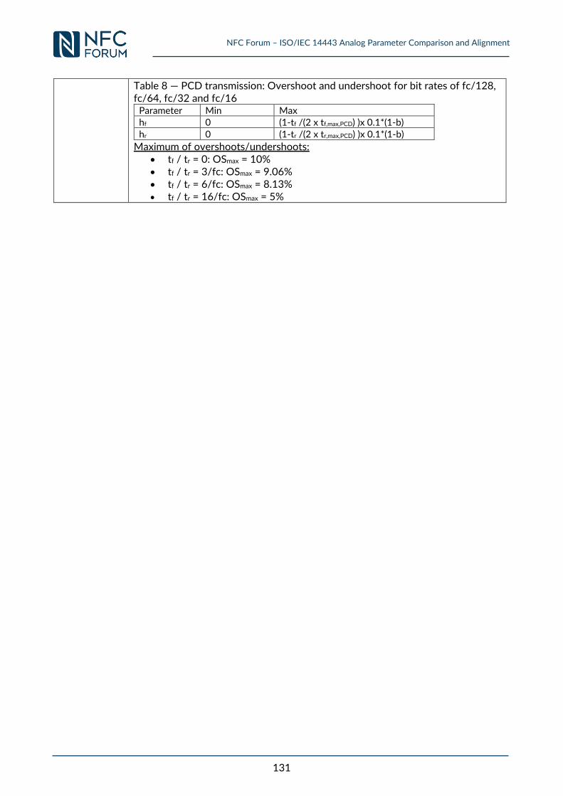
NFC Forum – ISO/IEC 14443 Analog Parameter Comparison and Alignment
131
Table 8 — PCD transmission: Overshoot and undershoot for bit rates of fc/128, fc/64, fc/32 and fc/16
Parameter Min Max hf 0 (1-tf /(2 x tf,max,PCD) )x 0.1*(1-b)
hr 0 (1-tr /(2 x tr,max,PCD) )x 0.1*(1-b)
Maximum of overshoots/undershoots: tf / tr = 0: OSmax = 10% tf / tr = 3/fc: OSmax = 9.06% tf / tr = 6/fc: OSmax = 8.13% tf / tr = 16/fc: OSmax = 5%
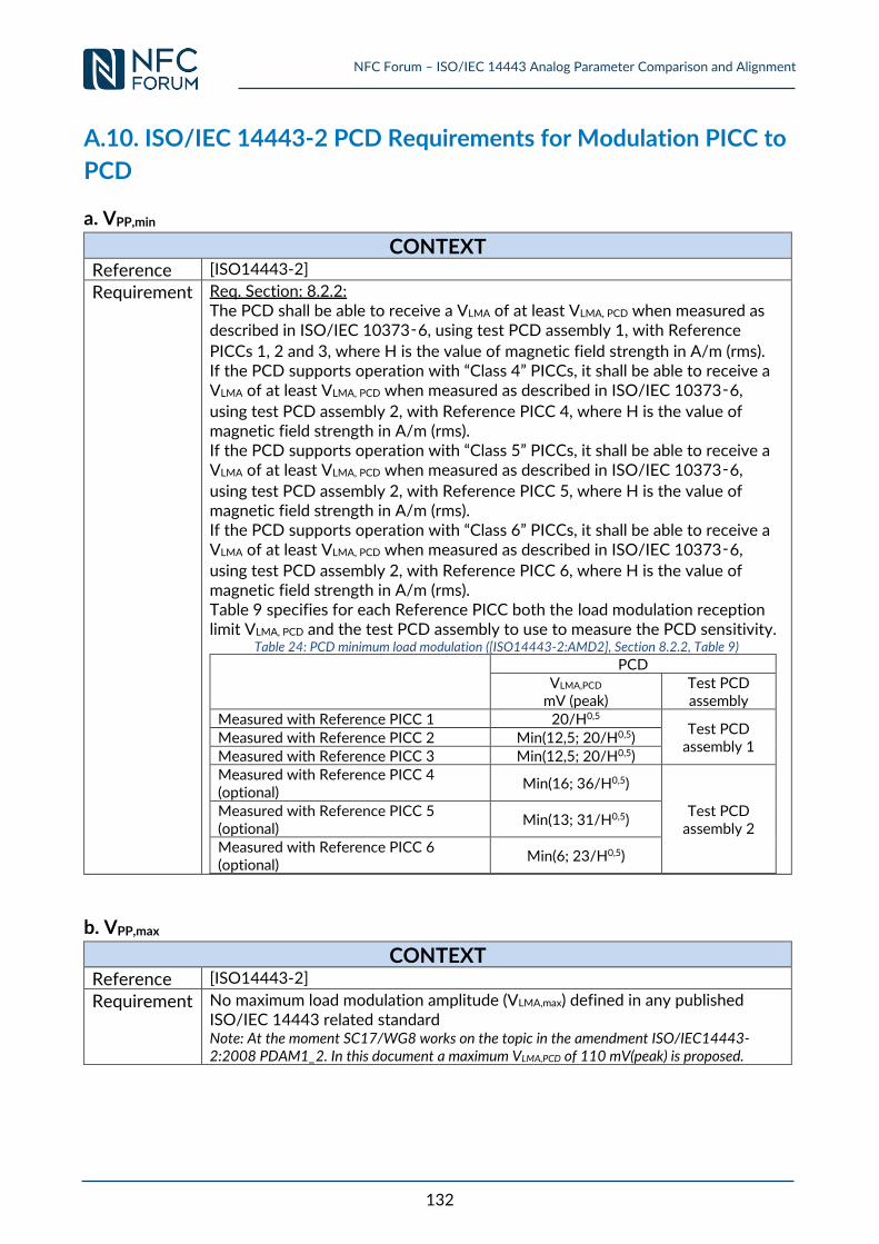
NFC Forum – ISO/IEC 14443 Analog Parameter Comparison and Alignment
132
A.10. ISO/IEC 14443-2 PCD Requirements for Modulation PICC to
PCD
a. VPP,min
CONTEXT
Reference [ISO14443-2]
Requirement Req. Section: 8.2.2: The PCD shall be able to receive a VLMA of at least VLMA, PCD when measured as described in ISO/IEC 10373‑6, using test PCD assembly 1, with Reference
PICCs 1, 2 and 3, where H is the value of magnetic field strength in A/m (rms). If the PCD supports operation with “Class 4” PICCs, it shall be able to receive a VLMA of at least VLMA, PCD when measured as described in ISO/IEC 10373‑6,
using test PCD assembly 2, with Reference PICC 4, where H is the value of magnetic field strength in A/m (rms). If the PCD supports operation with “Class 5” PICCs, it shall be able to receive a VLMA of at least VLMA, PCD when measured as described in ISO/IEC 10373‑6,
using test PCD assembly 2, with Reference PICC 5, where H is the value of magnetic field strength in A/m (rms). If the PCD supports operation with “Class 6” PICCs, it shall be able to receive a VLMA of at least VLMA, PCD when measured as described in ISO/IEC 10373‑6,
using test PCD assembly 2, with Reference PICC 6, where H is the value of magnetic field strength in A/m (rms). Table 9 specifies for each Reference PICC both the load modulation reception limit VLMA, PCD and the test PCD assembly to use to measure the PCD sensitivity.
Table 24: PCD minimum load modulation ([ISO14443-2:AMD2], Section 8.2.2, Table 9)
PCD VLMA,PCD
mV (peak) Test PCD assembly
Measured with Reference PICC 1 20/H0,5 Test PCD
assembly 1 Measured with Reference PICC 2 Min(12,5; 20/H0,5) Measured with Reference PICC 3 Min(12,5; 20/H0,5) Measured with Reference PICC 4 (optional)
Min(16; 36/H0,5)
Test PCD assembly 2
Measured with Reference PICC 5 (optional)
Min(13; 31/H0,5)
Measured with Reference PICC 6 (optional)
Min(6; 23/H0,5)
b. VPP,max
CONTEXT
Reference [ISO14443-2]
Requirement No maximum load modulation amplitude (VLMA,max) defined in any published ISO/IEC 14443 related standard Note: At the moment SC17/WG8 works on the topic in the amendment ISO/IEC14443-2:2008 PDAM1_2. In this document a maximum VLMA,PCD of 110 mV(peak) is proposed.
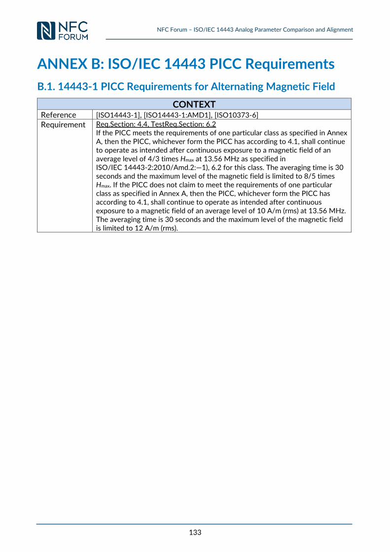
NFC Forum – ISO/IEC 14443 Analog Parameter Comparison and Alignment
133
ANNEX B: ISO/IEC 14443 PICC Requirements
B.1. 14443-1 PICC Requirements for Alternating Magnetic Field
CONTEXT Reference [ISO14443-1], [ISO14443-1:AMD1], [ISO10373-6] Requirement Req.Section: 4.4, TestReq.Section: 6.2
If the PICC meets the requirements of one particular class as specified in Annex A, then the PICC, whichever form the PICC has according to 4.1, shall continue to operate as intended after continuous exposure to a magnetic field of an average level of 4/3 times Hmax at 13.56 MHz as specified in ISO/IEC 14443-2:2010/Amd.2:—1), 6.2 for this class. The averaging time is 30 seconds and the maximum level of the magnetic field is limited to 8/5 times Hmax. If the PICC does not claim to meet the requirements of one particular class as specified in Annex A, then the PICC, whichever form the PICC has according to 4.1, shall continue to operate as intended after continuous exposure to a magnetic field of an average level of 10 A/m (rms) at 13.56 MHz. The averaging time is 30 seconds and the maximum level of the magnetic field is limited to 12 A/m (rms).
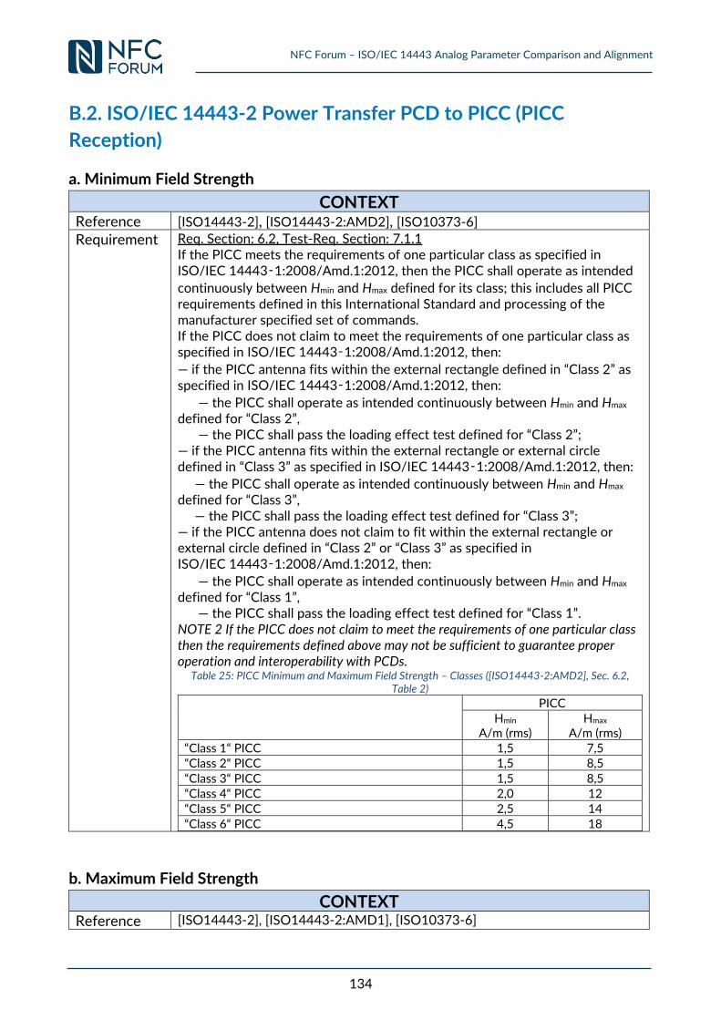
NFC Forum – ISO/IEC 14443 Analog Parameter Comparison and Alignment
134
B.2. ISO/IEC 14443-2 Power Transfer PCD to PICC (PICC
Reception)
a. Minimum Field Strength
CONTEXT Reference [ISO14443-2], [ISO14443-2:AMD2], [ISO10373-6] Requirement Req. Section: 6.2, Test-Req. Section: 7.1.1
If the PICC meets the requirements of one particular class as specified in ISO/IEC 14443‑1:2008/Amd.1:2012, then the PICC shall operate as intended
continuously between Hmin and Hmax defined for its class; this includes all PICC requirements defined in this International Standard and processing of the manufacturer specified set of commands. If the PICC does not claim to meet the requirements of one particular class as specified in ISO/IEC 14443‑1:2008/Amd.1:2012, then:
— if the PICC antenna fits within the external rectangle defined in “Class 2” as specified in ISO/IEC 14443‑1:2008/Amd.1:2012, then:
— the PICC shall operate as intended continuously between Hmin and Hmax defined for “Class 2”, — the PICC shall pass the loading effect test defined for “Class 2”; — if the PICC antenna fits within the external rectangle or external circle defined in “Class 3” as specified in ISO/IEC 14443‑1:2008/Amd.1:2012, then:
— the PICC shall operate as intended continuously between Hmin and Hmax defined for “Class 3”, — the PICC shall pass the loading effect test defined for “Class 3”; — if the PICC antenna does not claim to fit within the external rectangle or external circle defined in “Class 2” or “Class 3” as specified in ISO/IEC 14443‑1:2008/Amd.1:2012, then:
— the PICC shall operate as intended continuously between Hmin and Hmax defined for “Class 1”, — the PICC shall pass the loading effect test defined for “Class 1”. NOTE 2 If the PICC does not claim to meet the requirements of one particular class then the requirements defined above may not be sufficient to guarantee proper operation and interoperability with PCDs.
Table 25: PICC Minimum and Maximum Field Strength – Classes ([ISO14443-2:AMD2], Sec. 6.2, Table 2)
PICC
Hmin A/m (rms)
Hmax A/m (rms)
“Class 1“ PICC 1,5 7,5 “Class 2“ PICC 1,5 8,5
“Class 3“ PICC 1,5 8,5 “Class 4“ PICC 2,0 12 “Class 5“ PICC 2,5 14
“Class 6“ PICC 4,5 18
b. Maximum Field Strength
CONTEXT Reference [ISO14443-2], [ISO14443-2:AMD1], [ISO10373-6]

NFC Forum – ISO/IEC 14443 Analog Parameter Comparison and Alignment
135
Requirement Req. Section: 6.2, Test-Req. Section: 7.1.1 See above Requirement of 0) a. Minimum field strength.
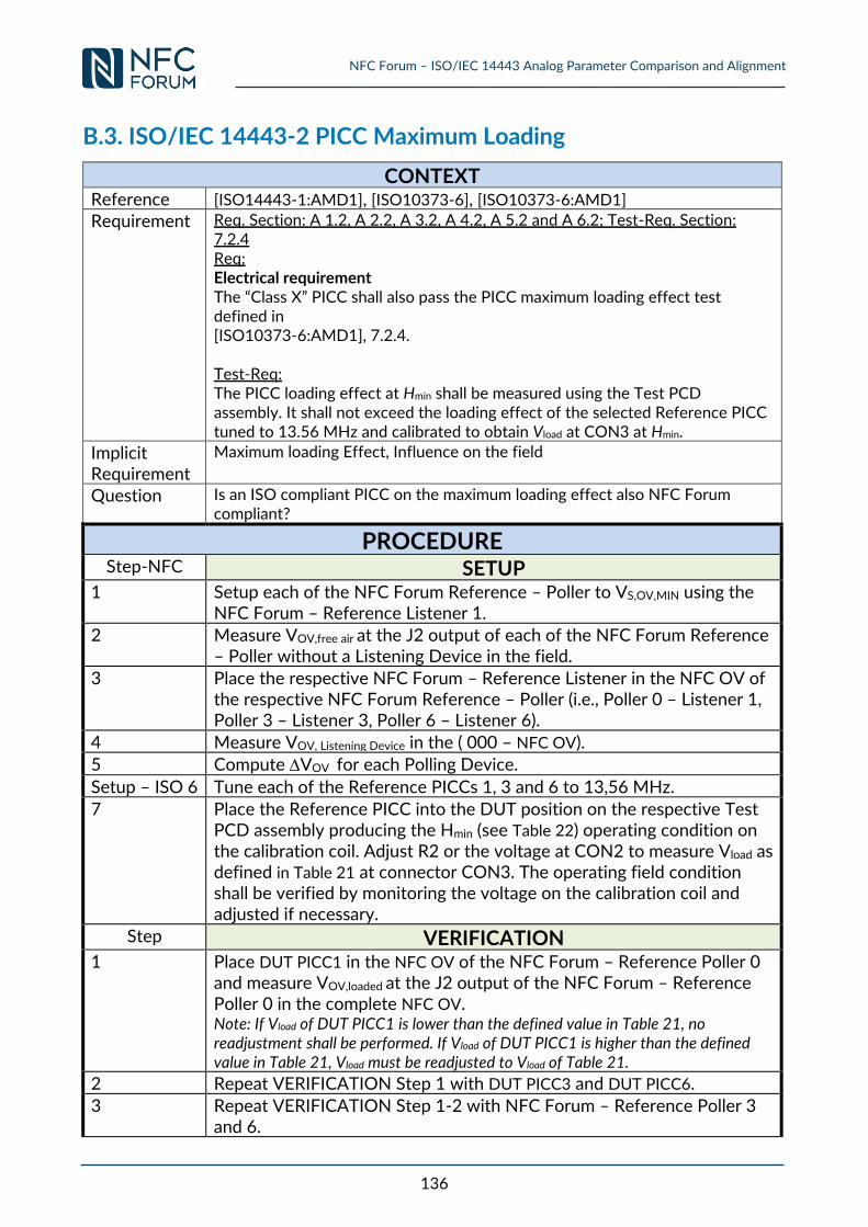
NFC Forum – ISO/IEC 14443 Analog Parameter Comparison and Alignment
136
B.3. ISO/IEC 14443-2 PICC Maximum Loading
CONTEXT Reference [ISO14443-1:AMD1], [ISO10373-6], [ISO10373-6:AMD1] Requirement Req. Section: A 1.2, A 2.2, A 3.2, A 4.2, A 5.2 and A 6.2; Test-Req. Section:
7.2.4 Req: Electrical requirement The “Class X” PICC shall also pass the PICC maximum loading effect test defined in [ISO10373-6:AMD1], 7.2.4. Test-Req: The PICC loading effect at Hmin shall be measured using the Test PCD assembly. It shall not exceed the loading effect of the selected Reference PICC tuned to 13.56 MHz and calibrated to obtain Vload at CON3 at Hmin.
Implicit Requirement
Maximum loading Effect, Influence on the field
Question Is an ISO compliant PICC on the maximum loading effect also NFC Forum compliant?
PROCEDURE Step-NFC SETUP
1 Setup each of the NFC Forum Reference – Poller to VS,OV,MIN using the NFC Forum – Reference Listener 1.
2 Measure VOV,free air at the J2 output of each of the NFC Forum Reference – Poller without a Listening Device in the field.
3 Place the respective NFC Forum – Reference Listener in the NFC OV of the respective NFC Forum Reference – Poller (i.e., Poller 0 – Listener 1, Poller 3 – Listener 3, Poller 6 – Listener 6).
4 Measure VOV, Listening Device in the ( 000 – NFC OV).
5 Compute VOV for each Polling Device.
Setup – ISO 6 Tune each of the Reference PICCs 1, 3 and 6 to 13,56 MHz.
7 Place the Reference PICC into the DUT position on the respective Test PCD assembly producing the Hmin (see Table 22) operating condition on the calibration coil. Adjust R2 or the voltage at CON2 to measure Vload as defined in Table 21 at connector CON3. The operating field condition shall be verified by monitoring the voltage on the calibration coil and adjusted if necessary.
Step VERIFICATION 1 Place DUT PICC1 in the NFC OV of the NFC Forum – Reference Poller 0
and measure VOV,loaded at the J2 output of the NFC Forum – Reference Poller 0 in the complete NFC OV. Note: If Vload of DUT PICC1 is lower than the defined value in Table 21, no readjustment shall be performed. If Vload of DUT PICC1 is higher than the defined value in Table 21, Vload must be readjusted to Vload of Table 21.
2 Repeat VERIFICATION Step 1 with DUT PICC3 and DUT PICC6.
3 Repeat VERIFICATION Step 1-2 with NFC Forum – Reference Poller 3 and 6.
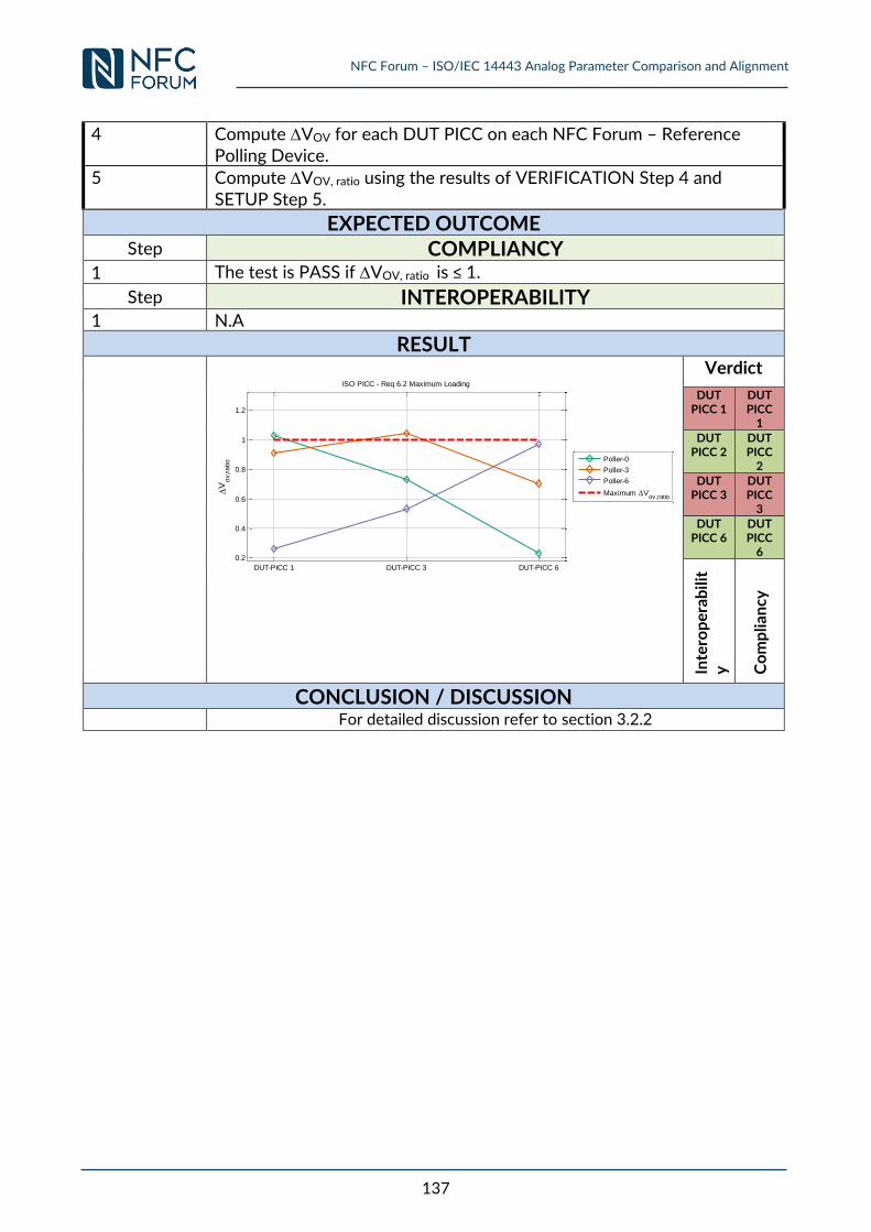
NFC Forum – ISO/IEC 14443 Analog Parameter Comparison and Alignment
137
4 Compute VOV for each DUT PICC on each NFC Forum – Reference Polling Device.
5 Compute VOV, ratio using the results of VERIFICATION Step 4 and SETUP Step 5.
EXPECTED OUTCOME
Step COMPLIANCY
1 The test is PASS if VOV, ratio is ≤ 1.
Step INTEROPERABILITY
1 N.A
RESULT
Verdict
DUT PICC 1
DUT PICC
1
DUT PICC 2
DUT PICC
2
DUT PICC 3
DUT PICC
3
DUT PICC 6
DUT PICC
6
Inte
rop
era
bil
ity
Co
mp
lia
ncy
CONCLUSION / DISCUSSION
For detailed discussion refer to section 3.2.2
DUT-PICC 1 DUT-PICC 3 DUT-PICC 6
0.2
0.4
0.6
0.8
1
1.2
V
ov,r
atio
ISO PICC - Req 6.2 Maximum Loading
Poller-0
Poller-3
Poller-6
Maximum Vov,ratio
NFC Forum – ISO/IEC 14443 Analog Parameter Comparison and Alignment
138
B.4. ISO/IEC 14443-2 PICC Requirement for the Carrier Frequency
fc
CONTEXT Reference [ISO14443-2], [ISO10373-6] Requirement Req. Section: 6.1 Frequency
The frequency fc of the RF operating field shall be 13.56 MHz ± 7 kHz. NFC Forum Reference
[NFC_ANA]
Requirement 4.5.2.1 When placed in the Operating Volume of the NFC Forum – Reference Polling Device, the Listening Device SHALL function properly with a carrier frequency between the Min and Max values of fS,C as defined in Appendix B.3, being generated by the NFC Forum – Reference Polling Device.
RESULT
The Requirements are providing a small difference from the specification point of view
CONCLUSION / DISCUSSION
No experimental measurement needed.

NFC Forum – ISO/IEC 14443 Analog Parameter Comparison and Alignment
139
B.5. ISO/IEC 14443-2 EMD PICC Requirement
CONTEXT
Reference [ISO14443-2:AMD1]
Requirement Req. Section: 10.2, Test-Req. Section: 7.2.2 This EMD requirement is applicable for "Class 1" PICC only. WARNING — Requirements for the classes other than "Class 1" will be specified in the future. However, the PICC limit for "Class 1" may ultimately be applied to "Class 2" and "Class 3" PICCs. The EMD level before PICC data transmission shall be below VE,PICC at a field strength H [A/m (rms)], for at least the duration of the low EMD time tE,PICC, when measured as specified in ISO/IEC 10373-6:2011/Amd.2. VE,PICC for "Class 1" PICC is:
2/3 + 3/H² [mV (peak)] for Hmin ≤ H ≤ 4,5 A/m (rms) 0,81 mV (peak) for 4,5 A/m(rms) ≤ H ≤ Hmax
During this low EMD time, the EMD level may exceed VE,PICC for no more than two short periods of 16/fc if:
it never exceeds 4 x VE,PICC and in case of two periods, the time between the two periods is greater than
1 etu. Figure 18 shows an illustration of such allowed EMD spikes. NOTE The low EMD time tE,PICC is defined in ISO/IEC 14443-3:2011/Amd.1. WARNING — This limit is referenced to "Class 1" only and values for the other classes may be specified in the future.
Note: EMD limit for PCD and PICC are identical. No margin is applied.
NFC Forum – ISO/IEC 14443 Analog Parameter Comparison and Alignment
140
B.6. ISO/IEC 14443-2 PICC Requirements for Transition to
POWER-OFF / IDLE State
a. Duration of Transition to POWER-OFF/IDLE state No experimental measurement needed.
b. VOV,RESET
There is no amplitude value defined in [ISO14443-2]or [ISO14443-3] similarly to VOV,RESET in NFC
Forum.
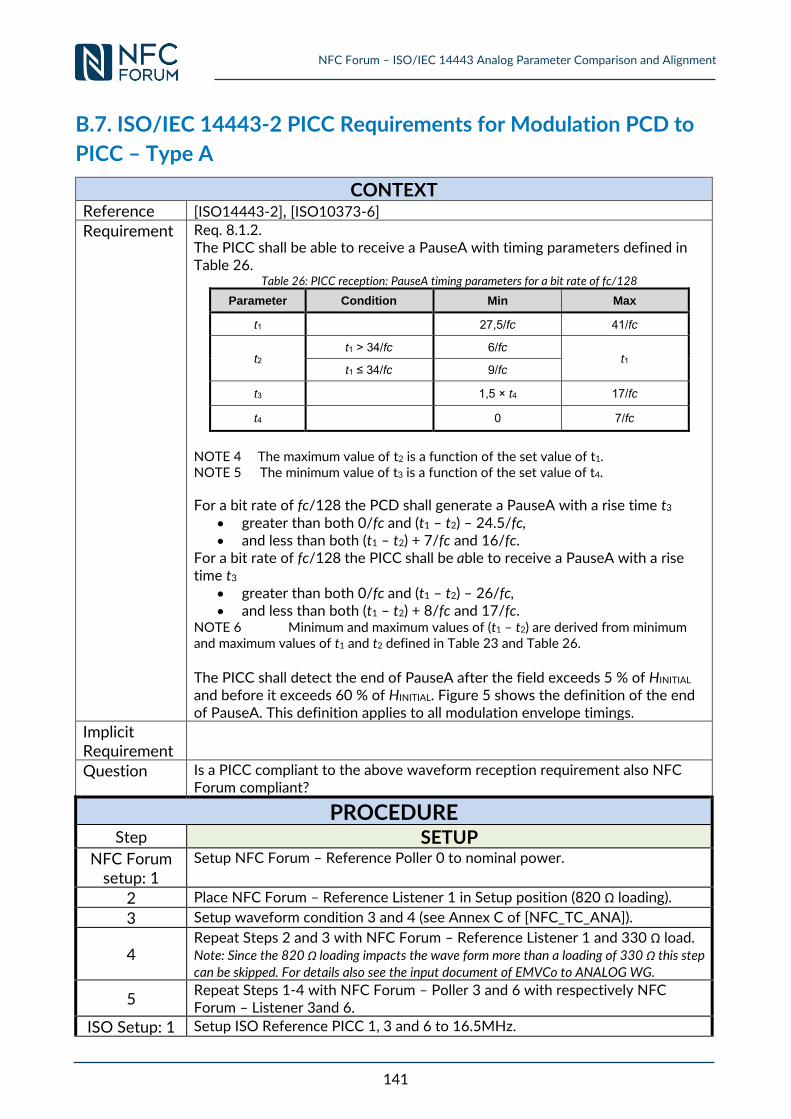
NFC Forum – ISO/IEC 14443 Analog Parameter Comparison and Alignment
141
B.7. ISO/IEC 14443-2 PICC Requirements for Modulation PCD to
PICC – Type A
CONTEXT
Reference [ISO14443-2], [ISO10373-6] Requirement Req. 8.1.2.
The PICC shall be able to receive a PauseA with timing parameters defined in Table 26.
Table 26: PICC reception: PauseA timing parameters for a bit rate of fc/128
Parameter Condition Min Max
t1 27,5/fc 41/fc
t2 t1 > 34/fc 6/fc
t1 t1 ≤ 34/fc 9/fc
t3 1,5 × t4 17/fc
t4 0 7/fc
NOTE 4 The maximum value of t2 is a function of the set value of t1. NOTE 5 The minimum value of t3 is a function of the set value of t4.
For a bit rate of fc/128 the PCD shall generate a PauseA with a rise time t3 greater than both 0/fc and (t1 – t2) – 24.5/fc, and less than both (t1 – t2) + 7/fc and 16/fc.
For a bit rate of fc/128 the PICC shall be able to receive a PauseA with a rise time t3
greater than both 0/fc and (t1 – t2) – 26/fc, and less than both (t1 – t2) + 8/fc and 17/fc.
NOTE 6 Minimum and maximum values of (t1 – t2) are derived from minimum and maximum values of t1 and t2 defined in Table 23 and Table 26.
The PICC shall detect the end of PauseA after the field exceeds 5 % of HINITIAL and before it exceeds 60 % of HINITIAL. Figure 5 shows the definition of the end of PauseA. This definition applies to all modulation envelope timings.
Implicit Requirement
Question Is a PICC compliant to the above waveform reception requirement also NFC Forum compliant?
PROCEDURE Step SETUP
NFC Forum setup: 1
Setup NFC Forum – Reference Poller 0 to nominal power.
2 Place NFC Forum – Reference Listener 1 in Setup position (820 Ω loading). 3 Setup waveform condition 3 and 4 (see Annex C of [NFC_TC_ANA]).
4 Repeat Steps 2 and 3 with NFC Forum – Reference Listener 1 and 330 Ω load. Note: Since the 820 Ω loading impacts the wave form more than a loading of 330 Ω this step
can be skipped. For details also see the input document of EMVCo to ANALOG WG.
5 Repeat Steps 1-4 with NFC Forum – Poller 3 and 6 with respectively NFC Forum – Listener 3and 6.
ISO Setup: 1 Setup ISO Reference PICC 1, 3 and 6 to 16.5MHz.
NFC Forum – ISO/IEC 14443 Analog Parameter Comparison and Alignment
142
Step VERIFICATION
1 Place each ISO Reference PICC 1, 3 and 6 in the complete NFC OV of the NFC Forum – Reference Poller 0 and adjust the load according to Table 21. Note: The R2 has to be re-adjusted for every NFC OV position.
2 Measure to waveform of the pick-up coil of the respective ISO Reference PICC.
3 Repeat Verification procedure steps 1-2 for NFC Forum – Reference Poller 3 and 6.
EXPECTED OUTCOME
Step COMPLIANCY
1
Compare the measured waveform parameter values of VERIFICATION Step 2 to the limits defined in [ISO14443-2]. The test is PASS if the measured waveform parameter values do not exceed the limits defined for the respective parameter.
Step INTEROPERABILITY CONCLUSION / DISCUSSION
Due to similar Reference Equipment used for PCD / Poller waveform measurement only a limit comparison is required. See Section 3.1.5 0) for a discussion.
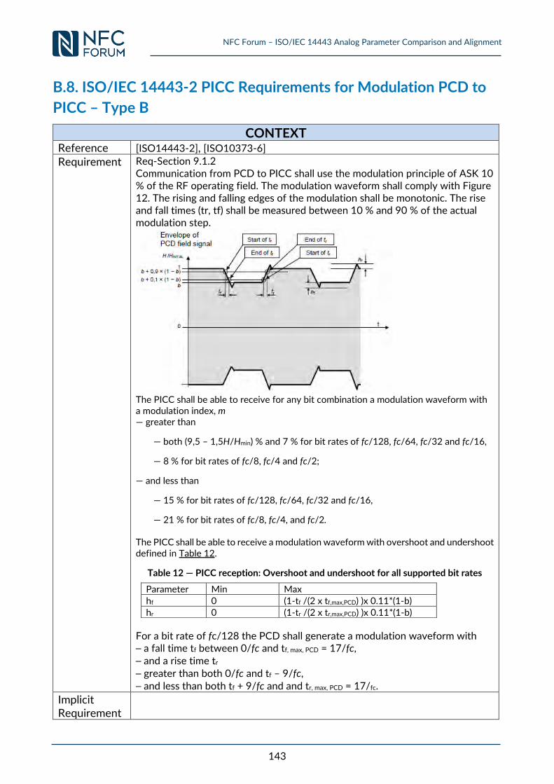
NFC Forum – ISO/IEC 14443 Analog Parameter Comparison and Alignment
143
B.8. ISO/IEC 14443-2 PICC Requirements for Modulation PCD to
PICC – Type B
CONTEXT
Reference [ISO14443-2], [ISO10373-6] Requirement Req-Section 9.1.2
Communication from PCD to PICC shall use the modulation principle of ASK 10 % of the RF operating field. The modulation waveform shall comply with Figure 12. The rising and falling edges of the modulation shall be monotonic. The rise and fall times (tr, tf) shall be measured between 10 % and 90 % of the actual modulation step.
The PICC shall be able to receive for any bit combination a modulation waveform with a modulation index, m — greater than
— both (9,5 – 1,5H/Hmin) % and 7 % for bit rates of fc/128, fc/64, fc/32 and fc/16,
— 8 % for bit rates of fc/8, fc/4 and fc/2;
— and less than
— 15 % for bit rates of fc/128, fc/64, fc/32 and fc/16,
— 21 % for bit rates of fc/8, fc/4, and fc/2.
The PICC shall be able to receive a modulation waveform with overshoot and undershoot defined in Table 12.
Table 12 — PICC reception: Overshoot and undershoot for all supported bit rates
Parameter Min Max
hf 0 (1-tf /(2 x tf,max,PCD) )x 0.11*(1-b) hr 0 (1-tr /(2 x tr,max,PCD) )x 0.11*(1-b)
For a bit rate of fc/128 the PCD shall generate a modulation waveform with ⎯ a fall time tf between 0/fc and tf, max, PCD = 17/fc, ⎯ and a rise time tr ⎯ greater than both 0/fc and tf – 9/fc, ⎯ and less than both tf + 9/fc and and tr, max, PCD = 17/fc.
Implicit Requirement
NFC Forum – ISO/IEC 14443 Analog Parameter Comparison and Alignment
144
Question Is a PICC compliant to the above waveform reception requirement also NFC Forum compliant?
PROCEDURE Step SETUP
NFC Forum setup: 1
Setup NFC Forum – Reference Poller 0 to nominal power.
2 Place NFC Forum – Reference Listener 1 in Setup position (820 Ω loading). 3 Setup waveform condition 3 and 4 (see Annex C of [NFC_TC_ANA]).
4 Repeat Steps 2 and 3 with NFC Forum – Reference Listener 1 and 330 Ω load. Note: Since the 820 Ω loading impacts the wave form more than a loading of 330 Ω this step
can be skipped. For details also see the input document of EMVCo to ANALOG WG.
5 Repeat Steps 1-4 with NFC Forum – Poller 3 and 6 with respectively NFC Forum – Listener 3and 6.
ISO Setup: 1 Setup ISO Reference PICC 1, 3 and 6 to 16.5MHz.
Step VERIFICATION
1 Place each ISO Reference PICC 1, 3 and 6 in the complete NFC OV of the NFC Forum – Reference Poller 0 and adjust the load according to Table 21. Note: The R2 has to be re-adjusted for every NFC OV position.
2 Measure to waveform of the pick-up coil of the respective ISO Reference PICC.
3 Repeat Verification procedure steps 1-2 for NFC Forum – Reference Poller 3 and 6.
EXPECTED OUTCOME
Step COMPLIANCY
1
Compare the measured waveform parameter values of VERIFICATION Step 2 to the limits defined in [ISO14443-2]. The test is PASS if the measured waveform parameter values do not exceed the limits defined for the respective parameter.
Step INTEROPERABILITY CONCLUSION / DISCUSSION
Due to similar Reference Equipment used for PCD / Poller waveform measurement only a limit comparison is required. See Section 3.1.6 0) for a discussion.
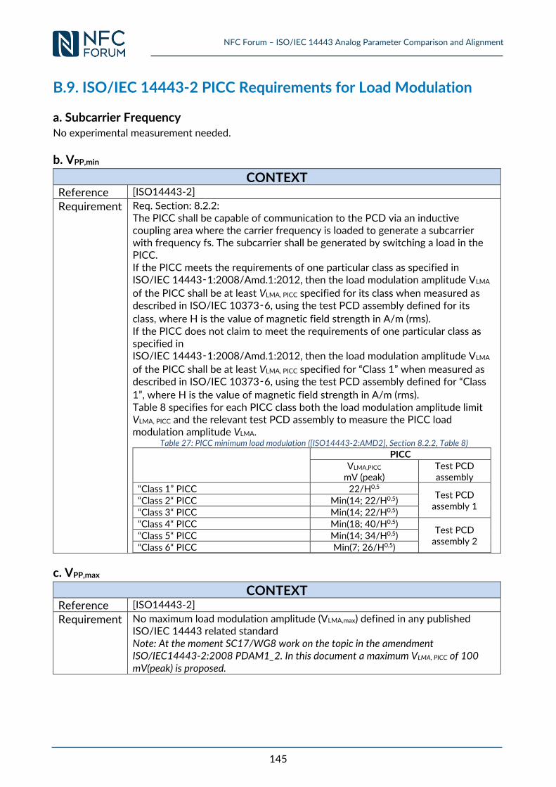
NFC Forum – ISO/IEC 14443 Analog Parameter Comparison and Alignment
145
B.9. ISO/IEC 14443-2 PICC Requirements for Load Modulation
a. Subcarrier Frequency No experimental measurement needed.
b. VPP,min
CONTEXT
Reference [ISO14443-2]
Requirement Req. Section: 8.2.2: The PICC shall be capable of communication to the PCD via an inductive coupling area where the carrier frequency is loaded to generate a subcarrier with frequency fs. The subcarrier shall be generated by switching a load in the PICC. If the PICC meets the requirements of one particular class as specified in ISO/IEC 14443‑1:2008/Amd.1:2012, then the load modulation amplitude VLMA
of the PICC shall be at least VLMA, PICC specified for its class when measured as described in ISO/IEC 10373‑6, using the test PCD assembly defined for its
class, where H is the value of magnetic field strength in A/m (rms). If the PICC does not claim to meet the requirements of one particular class as specified in ISO/IEC 14443‑1:2008/Amd.1:2012, then the load modulation amplitude VLMA
of the PICC shall be at least VLMA, PICC specified for “Class 1” when measured as described in ISO/IEC 10373‑6, using the test PCD assembly defined for “Class
1”, where H is the value of magnetic field strength in A/m (rms). Table 8 specifies for each PICC class both the load modulation amplitude limit VLMA, PICC and the relevant test PCD assembly to measure the PICC load modulation amplitude VLMA.
Table 27: PICC minimum load modulation ([ISO14443-2:AMD2], Section 8.2.2, Table 8)
PICC VLMA,PICC
mV (peak) Test PCD assembly
“Class 1” PICC 22/H0,5 Test PCD
assembly 1 “Class 2“ PICC Min(14; 22/H0,5) “Class 3“ PICC Min(14; 22/H0,5) “Class 4“ PICC Min(18; 40/H0,5)
Test PCD assembly 2
“Class 5“ PICC Min(14; 34/H0,5) “Class 6“ PICC Min(7; 26/H0,5)
c. VPP,max
CONTEXT
Reference [ISO14443-2]
Requirement No maximum load modulation amplitude (VLMA,max) defined in any published ISO/IEC 14443 related standard Note: At the moment SC17/WG8 work on the topic in the amendment ISO/IEC14443-2:2008 PDAM1_2. In this document a maximum VLMA, PICC of 100 mV(peak) is proposed.

NFC Forum – ISO/IEC 14443 Analog Parameter Comparison and Alignment
146
B.10. ISO/IEC 14443-2 PICC Requirements for Subcarrier
Modulation – Type A
No experimental measurement needed.
NFC Forum – ISO/IEC 14443 Analog Parameter Comparison and Alignment
147
B.11. ISO/IEC 14443-2 PICC Requirements for Subcarrier
Modulation – Type B
No experimental measurement needed.
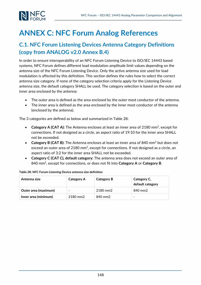
NFC Forum – ISO/IEC 14443 Analog Parameter Comparison and Alignment
148
ANNEX C: NFC Forum Analog References
C.1. NFC Forum Listening Devices Antenna Category Definitions
(copy from ANALOG v2.0 Annex B.4)
In order to ensure interoperability of an NFC Forum Listening Device to ISO/IEC 14443 based
systems, NFC Forum defines different load modulation amplitude limit values depending on the
antenna size of the NFC Forum Listening Device. Only the active antenna size used for load
modulation is affected by this definition. This section defines the rules how to select the correct
antenna size category. If none of the category selection criteria apply for the Listening Device
antenna size, the default category SHALL be used. The category selection is based on the outer and
inner area enclosed by the antenna:
The outer area is defined as the area enclosed by the outer most conductor of the antenna.
The inner area is defined as the area enclosed by the inner most conductor of the antenna
(enclosed by the antenna).
The 3 categories are defined as below and summarized in Table 28:
Category A (CAT A): The Antenna encloses at least an inner area of 2180 mm2, except for
connections. If not designed as a circle, an aspect ratio of 19:10 for the inner area SHALL
not be exceeded.
Category B (CAT B): The Antenna encloses at least an inner area of 840 mm2 but does not
exceed an outer area of 2180 mm2, except for connections. If not designed as a circle, an
aspect ratio of 3:2 for the inner area SHALL not be exceeded.
Category C (CAT C), default category: The antenna area does not exceed an outer area of
840 mm2, except for connections, or does not fit into Category A or Category B.
Table 28: NFC Forum Listening Device antenna size definition
Antenna size Category A Category B Category C,
default category
Outer area (maximum) - 2180 mm2 840 mm2
Inner area (minimum) 2180 mm2 840 mm2 -