extending iso/iec 14443 type a eavesdropping - perisens gmbh
TRANSCRIPT

Extending ISO/IEC 14443 Type A EavesdroppingRange using Higher Harmonics
Maximilian Engelhardt∗, Florian Pfeiffer†, Klaus Finkenzeller‡ and Erwin Biebl∗∗Fachgebiet Höchstfrequenztechnik, Technischen Universität München, Arcisstr. 21, 80333 München
Email: [email protected], [email protected]†perisens GmbH, Landwehrstr. 61, 80336 München, Email: [email protected]
‡Giesecke & Devrient GmbH, Prinzregentenstraße 159, 81607 München, Email: [email protected]
Abstract—Inductively coupled ISO/IEC 14443 compliantRFID systems are used in many security-relevant applications.A key security feature is their very short range of about 10 cm.Eavesdropping attack scenarios are a well known and recognisedthreat for these systems. In this paper, we show an approach,using higher-order harmonics to eavesdrop the data transmittedfrom a transponder to a RFID-reader (uplink). Practical distancesfor eavesdropping on higher-order harmonics are measuredfor exemplary ISO/IEC 14443 type A transponder and readerconfigurations in different environments.
I. INTRODUCTION
Inductively coupled ISO/IEC 14443 compliant RFID sys-tems are nowadays being used in a huge number of security-relevant applications such as payment (credit cards), ticketing(public transport and events), access control (company card)and identity verification (ePass, eID).
Typical ISO/IEC 14443 passive tags are designed to operateover a maximum distance of about 10 cm. The short commu-nication range of a smart card is also regarded as an importantsecurity feature. Extended range [1], skimming attacks [2] andeavesdropping are well known threats for these systems whichare seeking to overcome the short range. An extended rangeattack is the ability of an active tag to establish an unauthorisedcommunication with a reader. Skimming is the unauthorisedaccess of tag data without an authorised tag-reader connection.Eavesdropping is defined as unauthorised data access to anauthorised reader-tag communication.
Fig. 1. Eavesdropping attack of a RFID communication [3]
In several studies eavesdropping attack scenarios have beenanalysed theoretically and experimentally. In [4] we have
shown the theoretical limits of eavesdropping attacks, listeningto the uplink (tag to reader) at the fundamental wave at13.56 MHz of a contactless smart card, ID1 size. We resulted inan eavesdropping distance of between 2 m and approximately10 m, depending on the tag type, the environmental noise figureand the field strength applied to the tag.
Looking at the analogue front end of a transponder how-ever, one sees that the loop antenna is directly connected to arectifier circuit in the RFID-chip, providing the power supplyfor the chip. This in the simplest case is done, using the strongnonlinear characteristic of diodes. As we know, any nonlinear-ity in an electronic component generally causes higher-orderharmonics in the current, flowing through it. Therefore thishigher-order components must also be a part of the currentflowing through the transponder coil antenna connected to therectifier, where they cause a magnetic field which finally getsradiated into the proximity of the transponder.
Fig. 2. Schematic of the power supply, voltage regulation and generation ofload-modulation with a 848 kHz subcarrier of a RFID transponder circuit [3]
In this paper we focus on eavesdropping a transponderon the higher-order harmonics, generated by the nonlinearcharacteristic of the rectifier in the transponders analogue frontend.
II. ADVANTAGE IN EAVESDROPPING HIGH-ORDERHARMONICS
Receiving at higher frequencies offers several advantages:
A. Improved noise conditions
In the HF band the external noise with atmospheric, galac-tic and man-made noise is typically significantly greater thanthe internal receiver noise. [5] gives an overview of averagenoise levels of external noise sources including atmospheric,galactic and man-made noise. Depending on the frequency,
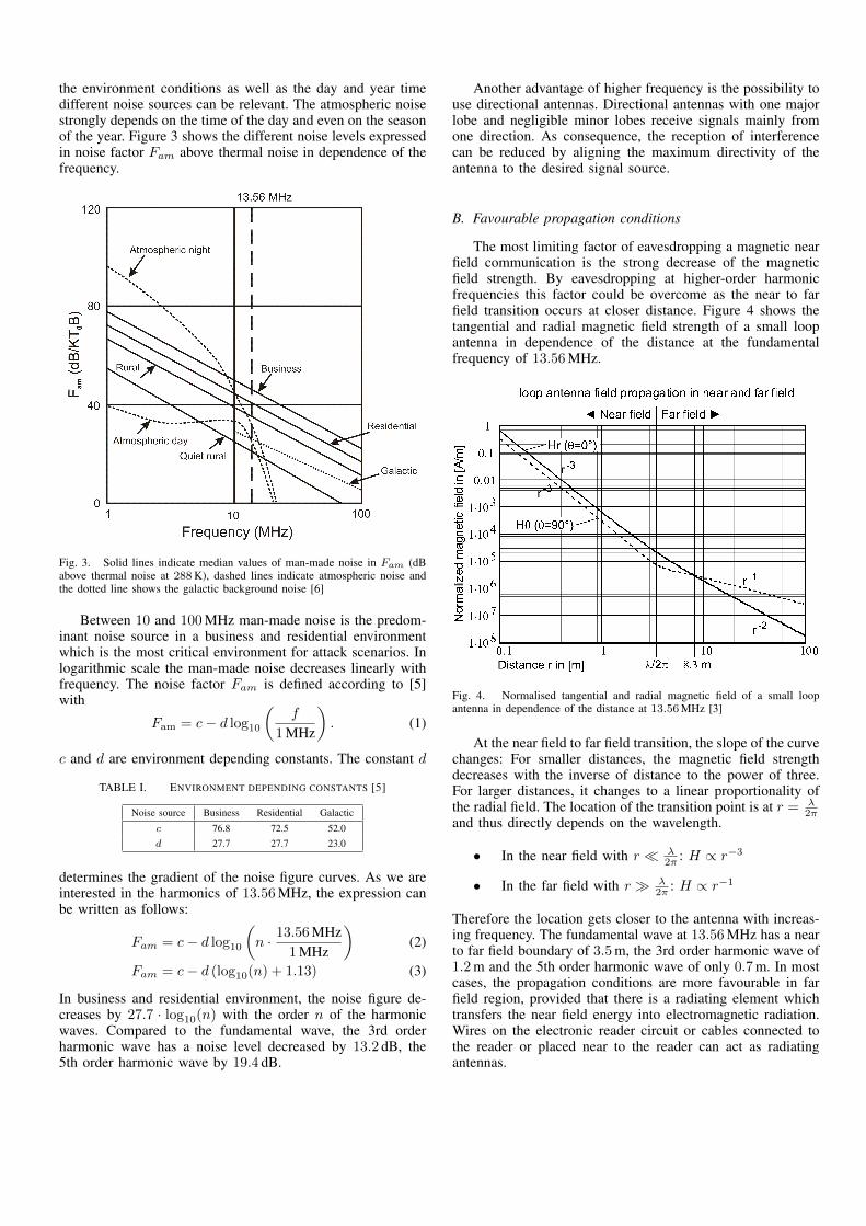
the environment conditions as well as the day and year timedifferent noise sources can be relevant. The atmospheric noisestrongly depends on the time of the day and even on the seasonof the year. Figure 3 shows the different noise levels expressedin noise factor Fam above thermal noise in dependence of thefrequency.
Fig. 3. Solid lines indicate median values of man-made noise in Fam (dBabove thermal noise at 288K), dashed lines indicate atmospheric noise andthe dotted line shows the galactic background noise [6]
Between 10 and 100 MHz man-made noise is the predom-inant noise source in a business and residential environmentwhich is the most critical environment for attack scenarios. Inlogarithmic scale the man-made noise decreases linearly withfrequency. The noise factor Fam is defined according to [5]with
Fam = c− d log10
(f
1 MHz
). (1)
c and d are environment depending constants. The constant d
TABLE I. ENVIRONMENT DEPENDING CONSTANTS [5]
Noise source Business Residential Galactic
c 76.8 72.5 52.0d 27.7 27.7 23.0
determines the gradient of the noise figure curves. As we areinterested in the harmonics of 13.56 MHz, the expression canbe written as follows:
Fam = c− d log10
(n · 13.56 MHz
1 MHz
)(2)
Fam = c− d (log10(n) + 1.13) (3)
In business and residential environment, the noise figure de-creases by 27.7 · log10(n) with the order n of the harmonicwaves. Compared to the fundamental wave, the 3rd orderharmonic wave has a noise level decreased by 13.2 dB, the5th order harmonic wave by 19.4 dB.
Another advantage of higher frequency is the possibility touse directional antennas. Directional antennas with one majorlobe and negligible minor lobes receive signals mainly fromone direction. As consequence, the reception of interferencecan be reduced by aligning the maximum directivity of theantenna to the desired signal source.
B. Favourable propagation conditions
The most limiting factor of eavesdropping a magnetic nearfield communication is the strong decrease of the magneticfield strength. By eavesdropping at higher-order harmonicfrequencies this factor could be overcome as the near to farfield transition occurs at closer distance. Figure 4 shows thetangential and radial magnetic field strength of a small loopantenna in dependence of the distance at the fundamentalfrequency of 13.56 MHz.
Fig. 4. Normalised tangential and radial magnetic field of a small loopantenna in dependence of the distance at 13.56MHz [3]
At the near field to far field transition, the slope of the curvechanges: For smaller distances, the magnetic field strengthdecreases with the inverse of distance to the power of three.For larger distances, it changes to a linear proportionality ofthe radial field. The location of the transition point is at r = λ
2πand thus directly depends on the wavelength.
• In the near field with r λ2π : H ∝ r−3
• In the far field with r λ2π : H ∝ r−1
Therefore the location gets closer to the antenna with increas-ing frequency. The fundamental wave at 13.56 MHz has a nearto far field boundary of 3.5 m, the 3rd order harmonic wave of1.2 m and the 5th order harmonic wave of only 0.7 m. In mostcases, the propagation conditions are more favourable in farfield region, provided that there is a radiating element whichtransfers the near field energy into electromagnetic radiation.Wires on the electronic reader circuit or cables connected tothe reader or placed near to the reader can act as radiatingantennas.

III. THEORY OF HIGH-ORDER HARMONICS GENERATION
The high-order harmonics are generated due to the non-linearities of the rectifier diodes. Typically, full-wave bridgerectifier circuits are used in smart cards. Such a commonlyused circuit is shown in figure 5.
13.56 MHz
2.5 µH
23 pF
4.7 Ω
10 nF 1 kΩ
Fig. 5. Schematic circuit of a bridge rectifier in receiving mode
To produce a steady DC supply, a smoothing capacitor isused at the output. The rectifier’s input is connected to thecoil antenna of the smartcard which is put resonant using acapacitor. The resonant frequency is adjusted to 13.56 MHz.
To analyse the behaviour of the rectifier circuit, it ismodelled using a Spice simulation tool. As diodes Schottkydiodes are used. In Figure 6, the spectrum of the output voltagewith the even harmonics of 13.56 MHz is shown.
0 50 100 150 200
−150
−100
−50
0DC
2×
13.56M
Hz
4×
13.56M
Hz
6×
13.56M
Hz
. . .
Frequency in MHz
Spec
tral
outp
utvo
ltage
indB
V
Fig. 6. Simulated frequency spectrum of voltage at the output of the bridgerectifier showing the even harmonics of 13.56MHz
This result can easily be explained: A full wave rectifierwith ideal diodes leaves the positive half cycle of an inputsine unchanged and clips the negative half cycle. The idealspectrum of such a rectified signal only consists of evenharmonics of the sine wave frequency. However, at the inputof the rectifier circuit the odd harmonics are produced. Seefigure 7 showing the simulated frequency spectrum of the coilcurrent. Since the odd harmonics occur directly at the input ofthe smartcard circuit, there is a great risk of radiating especially
0 50 100 150 200−160
−140
−120
−100
−80
−60
13.56M
Hz
3×
13.56M
Hz
5×
13.56M
Hz
. . .
Frequency in MHz
Spec
tral
coil
curr
ent
indB
A
Fig. 7. Simulated frequency spectrum of coil current at the input of thebridge rectifier showing odd harmonics of 13.56MHz
these lower odd harmonics (3rd order harmonic at 40.68 MHzand 5th order at 67.8 MHz).
IV. COMMUNICATION THEORY
A successful eavesdropping attack requires that the attackeris able to detect the bidirectional data communication betweena reader and a transponder with a sufficient accuracy. Thereliability of the data detection is directly connected to thebit error rate (BER). The BER itself is a function of themodulation scheme and the signal-to-noise ratio (SNR).
This paper concentrates on the eavesdropping of a readertransponder connection according to the ISO/IEC 14443type A standard at a default bitrate of 106 kbit/s. In the datatransfer from the reader to the transponder (downlink) thestandard specifies a 100 % Amplitude Shift Keying (ASK) withModified Miller coding. To ensure a continuous power supplyof the transponder, the width of the Miller glitches is limited to2–3 µs. For the transponder to reader communication (uplink)the transponder’s chip impedance is keyed by a modulated848 kHz subcarrier, usually by switching a modulation resistoron and off in the transponder-IC. The subcarrier itself is ASKmodulated with a Manchester coded data signal at the samebitrate (see figure 2).
As we are interested in the maximum reading distance, weassume optimum receiver architecture with a matched filterand a synchronous detector using an optimum threshold. Thematched filter maximises the SNR in presence of stochasticnoise, while the synchronous detector with optimum thresholdminimises the BER. For a binary ASK signal corrupted withadditive white Gaussian noise (AWGN) the probability of biterrors reads as [7]
BER =1
2erfc
(1
2
√SNRBB
), (4)
where SNRBB is the baseband SNR. For a coherent demodu-lation of the amplitude modulated (AM) signal the basebandSNR is twice as high as the high frequency SNR. At high

frequencies the noise power is divided equally into in-phaseand quadrature (I&Q) components. Assuming the desiredsignal as in-phase, half of the noise power can be removedafter down conversion. For coherent demodulation the BERreads as
BER =1
2erfc
(1
2
√2SNRHF
)(5)
and for non-coherent demodulation
BER =1
2erfc
(1
2
√SNRHF
). (6)
Figure 8 shows the BER in dependence of the SNR forcoherent and non-coherent demodulation.
Fig. 8. Bit error rate in dependence of SNR for binary ASK signal corruptedwith AWGN
The required BER depends on the amount of informationbits that are intended to be eavesdropped. It is obvious thatthe eavesdropping of a transponder-ID of only 4 bytes allowsa higher BER for reliable detection as a complete data frameof 256 bytes. For security applications as identity verification(ePass, eID) the ISO/IEC standard allows generation of arandom ID. Eavesdropping of such a randomly generatedID is completely worthless for every attacker. Therefore weconcentrate on the eavesdropping of data frames containing upto 4096 bytes according to [8]. Assuming no error-correctioncode, the probability that a frame with N bits arrives withoutany bit error (1 − FER) is N times the product of theprobability that a single bit arrives error:
1− FER = (1−BER)N (7)
In security relevant applications the communication isusually encrypted where a single bit error would significantlycomplicate or even prevent an unauthorised decryption. Ta-ble II shows the probability of an error-free detected frame independence of BER and frame length.
According to Table II, a BER of 0.1 % - as used in [9] -is not sufficient for a reliable error-free detection of a 64 or256 byte frame. Therefore, we also use a BER of 0.01 % inour study which allows an error-free detection of a 256 bytelong frame in 81.5 % of all attempts.
TABLE II. PROBABILITY THAT A FRAME ARRIVES WITH NO BITERRORS (WITHOUT ANY ERROR-CORRECTION)
Frame length BER1% 0.1% 0.01% 0.001%
4 byte 72.5% 96.6% 99.7% 100%16 byte 27.6% 88.0% 98.7% 99.9%64 byte 0.6% 59.9% 95.0% 99.5%
256 byte 0% 12.9% 81.5% 98.0%
A BER of 0.1 % implies a minimum SNRHF of 11.4 dBfor coherent and 14.4 dB for non-coherent demodulation (seeFigure 8). In our measurements we use an equivalent SNRBB
threshold of 14.4 dB for successful reception of the signal.
V. NEAR AND FAR FIELD COUPLING OF HIGH-ORDERHARMONICS
As proof of concept, initial field strength measurements arecarried out in the near and far field.
1) Near field Measurements: To determine the power of thegenerated harmonics we performed near field measurementsusing a small coil located on the surface of the smart cardwhile reading the smart card. Since the impedance of the coilis dependent on the frequency, we measured the inductivity ofthe coil and compensated the measured values accordingly.
jωL
un
R
i
uR
Fig. 9. Equivalent circuit of the measurement setup
Figure 9 shows the equivalent circuit of the measurement.R designates the 50 Ω input of the used spectrum analyser,jωL the inductivity of the coil and un the source voltage.Because the impedance grows with increasing frequency, uRwill decrease with constant source voltage. With this equivalentcircuit one can easily derive equation 8.
un = uRR + jωL
R(8)
For all our measurements we used a Mifare pegoda CLRD 701 reader from NXP and a 1K Mifare transponder cardfrom Philips. The reader was connected to a laptop with thesupplied 2 m long USB cable. Reader and laptop were placedat roughly the same distance so that the USB cable was aboutparallel to the ground.
Table III shows the power of the harmonics after compen-sating the effect of the coil. According to the simulated resultsin chapter III, the odd harmonics are noticeably stronger thanthe even harmonics. The 3rd order harmonic is the strongestwith 23 dB below the fundamental wave.

TABLE III. COMPARISON OF THE GENERATED HARMONICS
Harmonics 1 2 3 4 5 6 7
Frequency [MHz] 13.56 27.12 40.68 54.24 67.80 81.36 94.92
Power [dBc] 0 −54 −23 −58 −35 −56 −38
2) Far field Measurements: An crucial property for eaves-dropping higher order harmonics is the radiation of thoseinto the far field. As the signal of the transponder is thelimiting factor for eavesdropping an ISO/IEC 14443 Type ARFID communication [4], we conducted measurements at thefrequency of the upper side band of the transponder at differentorder harmonics.
In our measurements the Pegoda reader was connected tothe laptop using a USB cable. The laptop was placed at a heightof 0.5 m above ground, in a distance of about 2 m to the reader.The reader is about 1 m above ground. The complete setup isshown in figure 10.
Fig. 10. Reader connected to a laptop via USB cable which acted as antenna(marked in red) in the EMC chamber
It turned out that the field of the higher harmonic frequen-cies coupled to the USB cable and the cable acted as antenna.The best results could be achieved when the transponder cardwas placed eccentrically on the reader. Figure 11 shows thesetup we used in our measurements. In case of locating thetransponder card centrally to the reader, nearly no radiationoccurred.
Fig. 11. Exemplary positions of the transponder card on the reader forradiation of higher order harmonics into the far field
Table IV shows the measured electrical field strength of theharmonics at a distance of about 2.3 m from the reader. Thehighest field strength could be measured at the 3rd and 7thorder harmonics. As the spectrum of the 7th order harmonic
TABLE IV. MEASURED ELECTRIC FIELD STRENGTH OF THE RADIATEDHARMONICS AT THE UPPER SIDE BAND OF THE CARD SIGNAL
Harmonic 2 3 4 5
Frequency [MHz] 27.9675 41.5275 55.0875 68.6475
el. field strength [dB µV/m] −1 22 −7 −21
Harmonic 6 7 8 9
Frequency [MHz] 82.2075 95.7675 109.3275 122.8875
el. field strength [dB µV/m] −14 17 −11 −5
lies in the FM broadcasting radio band and the signal at the 3rdorder harmonic was stronger we decided to use this frequencyfor our further analysis.
VI. EAVESDROPPING OF 3RD ORDER HARMONIC
We conducted measurements at different locations withdifferent measurement equipment. As the limiting factor foreavesdropping an ISO/IEC 14443 type A communication isthe uplink signal we concentrated our analysis only on thissignal. Since the mixing products at the harmonics carry thespectrum of both, the reader and transponder communication,extracting the reader data is not much additional effort.
For our evaluation we made measurements in an exper-imental hall with a combined biconical and a log-periodicantenna from Rohde und Schwarz (HL562 ULTRALOG) aswell as in a long corridor using a much smaller SB 30-88-MU1 shortened quarter wavelength antenna from Procom.Both locations are at the Technische Universität München. Weintentionally wanted to perform measurements in an normalenvironment to simulate realistic eavesdropping attacks.
The measurements in the experimental hall were realisedusing a signal and spectrum analyser from Rohde und Schwarz.For the measurements in the corridor we used a self-developedreceiver hardware consisting of a low noise amplifier, bandpassfilter and a coherent receiver. The bandpass filter was tunedto the upper side band of the transponder signal at the 3rdorder harmonic, the receiver used a low cost TDA2542 ICfor demodulation the upper side band signal at 41.5275 MHz.The IQ baseband signal at the output of the receiver wasquantised and sampled for further digital processing using anoscilloscope. Together with the much smaller antenna used inour measurement this setup is a more realistic example for aneavesdropping attack. Figure 12 shows the measurement setupat the corridor.
Figure 13 displays the result of the measurements asSNRBB after matched filtering over distance. For comparisonwe also performed measurements at the fundamental wave.The measurements in the experimental hall were done forhorizontal polarisation, in the corridor we measured horizontaland vertical polarisation. During the measurements we onlycaptured the raw signal. Additional filtering and SNR calcula-tion was done later in the digital domain.
For a threshold value of 14.4 dB, as it is necessary for biterror rates smaller 0.01 %, we achieved a maximal eavesdrop-ping distance of 2.4 m at the fundamental wave. In contrast atthe 3rd order harmonic we were able to receive signals in as faras 18 m above this threshold. Noticeable are the SNR variationsin the region up to 15 m for the measurements in the corridor

Fig. 12. Measurement setup in the corridor. The laptop and reader can beseen in the background, in the foreground are the receiving antenna and thereception hardware.
0 5 10 15 20 25 30
10
15
20
25
30
14.4 dB
Distance in m
SN
RBB
indB
fund. wave3rd order harmonic
hall, H pol.corridor, V pol.corridor, H pol.
Fig. 13. Measured SNR versus antenna-reader distance for the fundamentalwave and the 3rd order harmonic. Measurement in the hall using horizontalpolarisation and in the corridor for vertical and horizontal polarisation.
in both polarisations. We explain this due to interference bymultipath propagation of the signal.
To rule out problems with only a specific transponder cardwe additionally conducted some tests with different transpon-der cards but achieved roughly the same results. In our casethe radiation of the 3rd harmonic occurred through the USBcable connecting the reader to the laptop. After adding a snap-on ferrite core to the USB cable at the readers side, we were
no longer able to receive any usable signal.
VII. CONCLUSION
Using higher harmonics for eavesdropping has obviousadvantages compared to eavesdropping at the fundamentalwave. In HF band the noise level decreases with increasingfrequencies and the near to far field transistion is getting closerto the antenna. In the far field, the field strength decreases onlylinearly with distance compared to the inverse of distance tothe power of three in the near field.
In this paper, we explain how higher order harmonicsare generated in a smartcard and how radiation can occur.We conducted measurements at the 3rd order harmonic for aexemplary ISO/IEC 14443 type A communication in differentlocations and achieved a maximal eavesdropping distanceof 18 m. This is much higher than the distances publishedat the fundamental wave. Table V gives an overview overdifferent published theoretical and experimental eavesdroppingdistances at the fundamental wave compared to our results.
TABLE V. COMPARISON OF OUR RESULTS TO OTHER PUBLICATIONS,/: THEORETICAL, õ: PRACTICAL, 5: COUPLING?
current Publications eavesdropping distance comment
Fundamental wave
õ Finke (2004) [10] 2m
õ BSI (2008) [11] 2.3m reading ID
õ Hanke (2008) [12] 1–3m (different locations) reading ID
õ5 Novotny (2008) [13] 8–15m (different cards) reading ID
/ NXP (2007) [9] 2.4–38.6m (different locations) BER < 0.1%
/ Pfeiffer (2012) [4] 2.1–7.7m (different locations) BER < 0.01%
õ Our results 2.2–2.4m (different locations) BER < 0.01%
3rd order harmonic
õ Our results 18m BER < 0.01%
Comparing the experimental studies, only the results of[13] with up to 15 m are close to our results at the 3rdharmonic. All other measurements - our own included - showmaximum eavesdropping ranges between 1 m and 3 m at thefundamental wave. Therefore, we assume coupling effects(e.g. in wires) as reason for the excessive range of [13]. Thephenomenon of coupling effects at the fundamental wave arementioned in [14].
In contrast to the fundamental wave, there is no systemantenna at the higher harmonics frequency. Therefore radiationis only possible if coupling to surrounding metal objects(e.g. cables, wires) which act as antennas occur. In ourmeasurements, the USB cable between reader and laptop actedas antenna. The intensity of radiation depended on the locationof the transponder on the reader. The best results could beachieved with an eccentrically position on the reader. By usinga simple snap-on ferrite at the reader’s side of the USB cablea sufficient suppression of the radiation could be achieved.
To avoid possible eavesdropping attacks with high rangesat higher harmonics, measures are needed to minimise har-monic generation or at least to prevent coupling to possiblesurrounding metal objects which can act as antennas. Typicallybridge rectifiers are used in transponders to provide the powersupply. At the input of these rectifiers, odd harmonics aregenerated and directly transformed in a magnetic field at

the transponder coil. Therefore, there is a large risk that themagnetic field of the higher harmonics couples through thereader circuit to a surrounding "antenna" where the energy istransfered into the far field. The harmonic generation has tobe suppressed at the bridge rectifier of the transponder card.At the reader’s side, the RF path to a surrounding "antenna"can be interrupted. This can be achieved, for example, byferrite based isolators at connected cables or harmonic filtersat critical spots in the reader circuit. In critical cases, on-sidespectrum measurements might be useful as coupling stronglydepends on the surrounding.
REFERENCES
[1] K. Finkenzeller, F. Pfeiffer, and E. Biebl, “Range extension of anISO/IEC 14443 type A RFID system with actively emulating loadmodulation,” RFID SysTech 2011; 7th European Workshop on SmartObjects: Systems, Technologies and Applications; Proceedings of, pp.1–10, may 2011.
[2] I. Kirschenbaum and A. Wool, “How to build a low-cost, extended-range RFID skimmer,” in 15th Usenix Security Symposium, 2006, pp.43–57.
[3] K. Finkenzeller, RFID-Handbuch, 6th ed. München: Hanser, 2012,http://rfid-handbook.com.
[4] F. Pfeiffer, K. Finkenzeller, and E. Biebl, “Theoretical limits of ISO/IEC14443 type A RFID eavesdropping attacks,” in Smart SysTech 2012- European Conference on Smart Objects, Systems and Technologies,2012.
[5] European Radiocommunications Committee (ERC), “Propagationmodel and interference range calculation for inductive systems 10 kHz– 30 MHz,” ERC report 69, 1999.
[6] C. Bianchi and A. Meloni, “Natural and man-made terrestrial electro-magnetic noise: an outlook,” Annals of Geophysics, vol. 50, no. 3, June2007.
[7] D. M. Pozar, Microwave and RF Design of Wireless Systems. NewYork [u.a.]: Wiley, 2001.
[8] “ISO/IEC 14443-4:2008 (2nd edition). identification cards - contactlessintegrated circuit(s) cards - proximity cards, part 4: Transmissionprotocol,” 2008.
[9] “Application note AN200701: ISO/IEC 14443 eavesdropping and acti-vation distance,” NXP, 2007.
[10] T. Finke and H. Kelter, “Radio frequency identification (RFID) – Abhör-möglichkeiten der Kommunikation zwischen Lesegerät und Transpon-der am Beispiel eines ISO 14443-Systems,” Bundesamt für Sicherheitin der Informationstechnik, 2004.
[11] “Messung der Abstrahleigenschaften von RFID-Systemen (MARS),Teilbericht 1,” Bundesamt für Sicherheit in der Informationstechnik,2008.
[12] G. Hancke, “Eavesdropping attacks on high-frequency RFID tokens,”in 4th Workshop on RFID Security (RFIDSec), 2008.
[13] D. Novotny, J. Guerrieri, M. Francis, and K. Remley, “HF RFIDelectromagnetic emissions and performance,” in Electromagnetic Com-patibility, 2008. EMC 2008. IEEE International Symposium on, aug.2008, pp. 1–7.
[14] P.-H. Thevenon, O. Savry, S. Tedjini, and R. Malherbi-Martins, “Attackson the HF physical layer of contactless and RFID systems,” in CurrentTrends and Challenges in RFID. Cornel Turcu (Ed.), 2011.
ABOUT THE AUTHORS
Maximilian Engelhardt wasborn in Karlsruhe, Germany,in 1986. He is currentlystudying electrical engineeringat the Technische UniversitätMünchen, Munich, Germany.In 2012 he wrote his BachelorThesis at the FachgebietHöchstfrequenztechnik. Heis now working towardscompleting his Diplomadegree.
Florian Pfeiffer was bornin Starnberg, Germany, in1976. He received the Dipl.-Wirtsch.-Ing. (FH) degree inindustrial engineering fromthe Fachhochschule München,Munich, Germany, in 2001, theDipl.-Ing. and Dr.-Ing. degreesin electrical engineering fromthe Technische UniversitätMünchen, Munich, Germany,in 2005 and 2010, respectively.In 2009, together with Erwin
M. Biebl, he founded an engineering company for highfrequency electronics (perisens GmbH), where he is chiefexecutive.
Klaus Finkenzeller was bornin Ingolstadt, Germany in 1962.He received his Dipl.-Ing. (FH)degree in electrical engineeringfrom the Munich University ofApplied Sciences (FH), MunichGermany. In 1989 he joinedGiesecke & Devrient. Since1994 he has been involved inthe development of contactlesssmart cards and RIFD sys-tems. He is currently work-ing as a technology consultantfor RFID/security, where he isinvolved in basic development
and innovation projects. Since 1994 he has been engaged in thestandardisation of contactless smartcards and RFID Systems(DIN NI 17.8, NI 31.4, SC17/WG8), where he has been vicechair of the German DIN NI 17.8 (ISO/IEC 14443) for morethan 10 years now. Up to now he has published more than130 individual patent applications, mainly in the RFID fieldof technology. In 1998 he published the RFID handbook,which now is available in its 6th edition and in 7 differentlanguages. In 2008 Klaus Finkenzeller received the FraunhoferSIT smartcard price for his work on RFID, especially the RFIDhandbook.
Erwin M. Biebl was bornin Munich, Germany, in 1959.He received the Dipl.-Ing., Dr.-Ing., and Habilitation degreesfrom the Technische UniversitätMünchen, Munich, Germany, in1986, 1990, and 1993, respec-tively. In 1986, he joined Ro-hde & Schwarz, Munich, Ger-many, where he was involved inthe development of mobile ra-dio communication test sets. In1988, he was with the Lehrstuhlfür Hochfrequenztechnik, Tech-
nische Universität München. In 1998, he became a Pro-fessor and Head of the Optical and Quasi-Optical SystemsGroup. Since 1999, he has been Head of the FachgebietHöchstfrequenztechnik, Technische Universität München. Hehas been engaged in research on optical communications,integrated optics, and computational electromagnetics. Hiscurrent interests include quasi-optical measurement techniques,design and characterization of microwave and millimeter-wavedevices and components, sensor and communication systems,and cooperative approaches to sensor and communicationsystems and networks. Dr. Biebl is a member of the Informa-tionstechnische Gesellschaft (ITG) in the Verband DeutscherElektrotechniker (VDE), Germany, a senior member of theIEEE and an appointed member of the commission B of URSI,Germany.