next generation networks -the technologies and enablers
TRANSCRIPT

TECHNISCHE UNIVERSITÄT BERLIN
MASTER THESIS
Next Generation Networks -The Technologiesand Enablers
Author:
Anna Sofía Bidot García
Supervisor:
Manzoor A. Khan
A thesis submitted in fulfilment of the requirements
for the degree of Master of Telecommunications Engineering
IV Fakultät Elektrotechnik und Informatik
DAI-Labor
May 2015

Declaration of Authorship
I, Anna Sofía Bidot García, declare that this thesis titled, ’Next Generation Networks -The
Technologies and Enablers ’ and the work presented in it are my own. I confirm that:
� This work was done wholly or mainly while in candidature for a research degree at this
University.
� Where any part of this thesis has previously been submitted for a degree or any other
qualification at this University or any other institution, this has been clearly stated.
� Where I have consulted the published work of others, this is always clearly attributed.
� Where I have quoted from the work of others, the source is always given. With the excep-
tion of such quotations, this thesis is entirely my own work.
� I have acknowledged all main sources of help.
� Where the thesis is based on work done by myself jointly with others, I have made clear
exactly what was done by others and what I have contributed myself.
Signed:
Date:
i

Abstract
While consumers are currently yearning for 4G smartphones, laboratories and some of the
biggest companies are already working to develop its successor: the 5th generation networks.
5G will alter current technologies as we know them today. Software Defined Networking (SDN)
will be the architecture used to deploy 5G. This thesis introduces the reader to the world of
SDN. SDN breaks away from the conventional model of network, decoupling the network in-
frastructure from the applications and services it provides. The global network control in SDN
is achieved by centralizing the logic function control plane. An element called ’Controller’ im-
plements the behavior rules of the switching elements.
Essentially, the objective of this paper is to present an overview of both the challenges and the
vision of future networks, along with the analytical explanations and the precise definitions of
cloud computing, SDN and Network Function Virtualization (VTN). OpenStack, as a cloud-
computing platform is also presented, as well as the OpenFlow Protocol and Mininet, a network
emulator tool. Additionally, the controller OpenDaylight is utilized to exhibit the extensive ca-
pabilities and immense potential of SDN network.
In this thesis, the OpenDaylight project is illustrated, implying its current projects and its techni-
cal aspects. This is in conjuntion with an in-depth view of the OpenDaylight Controller, where
the Service Abstraction Layer (SAL) resides. As a result of the application oriented extensible
north-bound architecture, the two Northbound APIs (OSGi services and RESTful web services)
are accessible. Finally, a progressive system is delineated, which demonstrates the technique of
writing an OpenDaylight application using all three different methods - either with API Driven
SAL, Model Driven SAL or with RESTful web services-. Supplementary to this is a test-case
called "Solving a DoS attack", in which the AD-SAL and REST API methods are utilized as
solutions to the attack. This illustrates how SDN architecture, through the OpenDaylight Con-
troller, is able to modify a network.

Acknowledgements
First of all, I would like to thank my family, my parents Heiner Bidot and Francisca García, my
sister Emily Bidot and my aunts Heidi Bidot and Gundi Bidot. Without them, I wouldn’t be
who I am today and I would never have gotten this far. Thank you so much for your constant
support, and for always believing in me. I really appreciate your help throughout my life as a
student, firstly in Mallorca, then in Barcelona and finally in Berlin.
My sincere thanks to my supervisor Dr.-Eng. Manzoor Ahmed Khan for his guidance and for
introducing me to the fascinating Software Defined Networking world. I would like to thank
him also for giving me the opportunity of working with him in the "Tel Gebäude". Not only was
it a great experience but also a pleasure to have one of the best views of Berlin.
Thanks also to professor Dr.-Eng. Juan Luis Gorricho, who agreed to be my supervisor in
Barcelona. I really appreciate his help and his kind attention throughout my thesis.
A special thanks to Gary Beecher, who has been there for me, through ups and downs. He,
despite not belonging to the science world, always helped and listened to me, giving me his best
advice and motivation.
And finally, thank you to all of my friends. Those I met here in Berlin, with whom I enjoyed this
amazing city. Thank you to my university colleagues in Barcelona, with whom I shared lots of
laughs and fun as well as many hours of study. Also to my friends outside of university (Bernat,
Cristina J., Cristina M., Laura, Loli, María, Miriam and Sandra) who, despite the time and long
distance, have been always there for me.
iii

Agradecimientos
Darle las gracias ante todo a mi familia, mis padres Heiner Bidot y Francisca García, a mi her-
mana Emily Bidot y a mis tías Heidi Bidot y Gundi Bidot. Sin ellos no sería quien soy hoy ni
habría llegado hasta donde he llegado. Mil gracias por el apoyo constante, por creer siempre en
mí. Realmente aprecio la ayuda incondicional a lo largo de mi vida como estudiante, primero
en Mallorca, luego en Barcelona y finalmente en Berlín.
Mis más sincero agradecimiento a mi supervisor Dr.-Ing. Manzoor Ahmed Khan, quien me
ha guiado e introducido al fascinante mundo de las redes definidas por software. Me gus-
taría agradecerle también por la oportunidad que se me ha brindado de trabajar con él en "Tel
Gebäude". No sólo ha sido una muy buena experiencia, sino también ha sido un placer poder
disfrutar día a día de una de las mejores vistas de Berlín.
Gracias también al profesor Dr.-Ing. Juan Luis Gorricho, quien aceptó ser mi supervisor en
Barcelona. Agradezco realmente su ayuda y su siempre amable atención durante el proyecto.
Agradecer especialmente a Gary Beecher, quien ha estado a mi lado tanto para los buenos mo-
mentos como para los no tan buenos. Él, aun no perteneciendo al mundo científico, ha sabido
ayudarme y escucharme, motivándome y aconsejándome en todo momento.
Y por último, pero no menos importante, a todas mis amistades. Aquellas que he hecho aquí en
Berlín y con las que he disfrutado de esta magnífica ciudad. A mis compañeros de carrera en
Barcelona, con los que he compartido millones de risas e infinitas horas de estudio. Y agradecer
también a mis amigos fuera de ella (Bernat, Cristina J., Cristina M., Laura, Loli, María, Miriam
y Sandra) quienes a pesar del tiempo y la distancia han estado siempre a mi lado.
iv

List of Figures
2.1 Cloud Services . . . . . . . . . . . . . . . . . . . . . . . . . . . . . . . . . . 72.2 SDN basic Arcuitecture . . . . . . . . . . . . . . . . . . . . . . . . . . . . . . 112.3 NFV vision Source: https://network-functions-virtualization.com . . . . . . . . 13
3.1 Horizon Dashboard . . . . . . . . . . . . . . . . . . . . . . . . . . . . . . . . 21
4.1 Traditional architecture vs. SDN . . . . . . . . . . . . . . . . . . . . . . . . . 284.2 SDN Layers . . . . . . . . . . . . . . . . . . . . . . . . . . . . . . . . . . . . 304.3 Switch Components . . . . . . . . . . . . . . . . . . . . . . . . . . . . . . . . 344.4 Packet processing . . . . . . . . . . . . . . . . . . . . . . . . . . . . . . . . . 354.5 From traditional networks to SDN . . . . . . . . . . . . . . . . . . . . . . . . 364.6 Mininet Source: http://mininet.org . . . . . . . . . . . . . . . . . . . . . . . . 374.7 Scenario 1 switch and 2 hosts . . . . . . . . . . . . . . . . . . . . . . . . . . . 404.8 sudo mn command . . . . . . . . . . . . . . . . . . . . . . . . . . . . . . . . 404.9 nodes, dump and net commands . . . . . . . . . . . . . . . . . . . . . . . . . 414.10 h1 ifconfig command . . . . . . . . . . . . . . . . . . . . . . . . . . . . . . . 414.11 s1 ifconfig command . . . . . . . . . . . . . . . . . . . . . . . . . . . . . . . 424.12 Network topology with 2 switches and 6 hosts . . . . . . . . . . . . . . . . . . 434.13 Virtual network topology example . . . . . . . . . . . . . . . . . . . . . . . . 44
5.1 Technical Overview Source: http://www.opendaylight.org . . . . . . . . . . . . 485.2 Controller architecture . . . . . . . . . . . . . . . . . . . . . . . . . . . . . . 495.3 Service Abstraction Layer Source: http://www.opendaylight.org . . . . . . . . 505.4 From AD-SAL to MD-SAL Source: https://wiki.opendaylight.org MD-SAL
App Tutorial . . . . . . . . . . . . . . . . . . . . . . . . . . . . . . . . . . . . 52
6.1 Two ways of visualizing an application in ODL platform . . . . . . . . . . . . 556.2 Scenario used for AD-SAL application . . . . . . . . . . . . . . . . . . . . . . 576.3 pingall unreachable . . . . . . . . . . . . . . . . . . . . . . . . . . . . . . . . 626.4 Results . . . . . . . . . . . . . . . . . . . . . . . . . . . . . . . . . . . . . . . 636.5 MD-SAL Software Architecture View Source: https://wiki.opendaylight.org -
MD-SAL App Tutorial . . . . . . . . . . . . . . . . . . . . . . . . . . . . . . 636.6 Building a Pluggin/Application Source Os2014-md-sal-tutorial.pdf . . . . . . . 656.7 GET Network Topology AD-SAL . . . . . . . . . . . . . . . . . . . . . . . . 766.8 GET Flow Statistics AD-SAL . . . . . . . . . . . . . . . . . . . . . . . . . . 776.9 GET Switches AD-SAL . . . . . . . . . . . . . . . . . . . . . . . . . . . . . 776.10 RESTCONF apidoc . . . . . . . . . . . . . . . . . . . . . . . . . . . . . . . . 786.11 Get Data RESTCONF . . . . . . . . . . . . . . . . . . . . . . . . . . . . . . . 786.12 Flow tables before adding flow . . . . . . . . . . . . . . . . . . . . . . . . . . 80
v

List of Figures vi
6.13 PUT Flow . . . . . . . . . . . . . . . . . . . . . . . . . . . . . . . . . . . . . 806.14 Results . . . . . . . . . . . . . . . . . . . . . . . . . . . . . . . . . . . . . . . 80

List of Tables
2.1 Published specifications on NFV . . . . . . . . . . . . . . . . . . . . . . . . . 15
3.1 OpenStack Components . . . . . . . . . . . . . . . . . . . . . . . . . . . . . . 22
4.1 Controllers comparison . . . . . . . . . . . . . . . . . . . . . . . . . . . . . . 31
5.1 Important bundles OpenDaylight . . . . . . . . . . . . . . . . . . . . . . . . . 515.2 Differences between AD-SAL and MD-SAL Source: http://sdntutorials.com/difference-
between-ad-sal-and-md-sal . . . . . . . . . . . . . . . . . . . . . . . . . . . . 53
vii

Contents
Declaration of Authorship i
Abstract ii
Acknowledgements iii
Agradecimientos iv
List of Figures v
List of Tables vii
Contents viii
1 Introduction 11.1 Motivation . . . . . . . . . . . . . . . . . . . . . . . . . . . . . . . . . . . . . 11.2 Scope . . . . . . . . . . . . . . . . . . . . . . . . . . . . . . . . . . . . . . . 21.3 Outline . . . . . . . . . . . . . . . . . . . . . . . . . . . . . . . . . . . . . . 2
2 State of the Art Technologies 42.1 Cloud Computing . . . . . . . . . . . . . . . . . . . . . . . . . . . . . . . . . 4
2.1.1 Cloud services . . . . . . . . . . . . . . . . . . . . . . . . . . . . . . 62.1.1.1 Examples . . . . . . . . . . . . . . . . . . . . . . . . . . . 8
2.1.2 Deployment Models . . . . . . . . . . . . . . . . . . . . . . . . . . . 82.2 Software Defined Networking . . . . . . . . . . . . . . . . . . . . . . . . . . 102.3 Network Functions Virtualization . . . . . . . . . . . . . . . . . . . . . . . . . 11
2.3.1 NFV technology . . . . . . . . . . . . . . . . . . . . . . . . . . . . . 122.3.2 NFV definition . . . . . . . . . . . . . . . . . . . . . . . . . . . . . . 12
2.3.2.1 European Telecommunications Standards Institute . . . . . . 132.3.2.2 Benefits of NFV . . . . . . . . . . . . . . . . . . . . . . . . 16
3 OpenStack 183.1 OpenStack Objective . . . . . . . . . . . . . . . . . . . . . . . . . . . . . . . 183.2 What is OpenStack? . . . . . . . . . . . . . . . . . . . . . . . . . . . . . . . . 193.3 How to install multi nodes in OpenStack . . . . . . . . . . . . . . . . . . . . . 23
viii

List of Tables ix
4 Software Defined Networking 274.1 SDN, an Introduction . . . . . . . . . . . . . . . . . . . . . . . . . . . . . . . 27
4.1.1 Motivation to use SDN . . . . . . . . . . . . . . . . . . . . . . . . . . 284.1.2 Architecture . . . . . . . . . . . . . . . . . . . . . . . . . . . . . . . . 29
4.2 Controllers . . . . . . . . . . . . . . . . . . . . . . . . . . . . . . . . . . . . 304.2.1 NOX . . . . . . . . . . . . . . . . . . . . . . . . . . . . . . . . . . . 324.2.2 POX . . . . . . . . . . . . . . . . . . . . . . . . . . . . . . . . . . . . 324.2.3 Beacon . . . . . . . . . . . . . . . . . . . . . . . . . . . . . . . . . . 324.2.4 Floodlight . . . . . . . . . . . . . . . . . . . . . . . . . . . . . . . . . 324.2.5 OpenDaylight . . . . . . . . . . . . . . . . . . . . . . . . . . . . . . . 33
4.3 OpenFlow . . . . . . . . . . . . . . . . . . . . . . . . . . . . . . . . . . . . . 334.3.1 OpenFlow Switch . . . . . . . . . . . . . . . . . . . . . . . . . . . . . 344.3.2 SDN and OpenFlow . . . . . . . . . . . . . . . . . . . . . . . . . . . 36
4.4 Mininet . . . . . . . . . . . . . . . . . . . . . . . . . . . . . . . . . . . . . . 374.4.1 Procedure . . . . . . . . . . . . . . . . . . . . . . . . . . . . . . . . . 384.4.2 Study of a network topology . . . . . . . . . . . . . . . . . . . . . . . 394.4.3 Python API Examples . . . . . . . . . . . . . . . . . . . . . . . . . . 424.4.4 Creating a virtual network topology . . . . . . . . . . . . . . . . . . . 43
5 OpenDaylight 455.1 OpenDaylight, a first view . . . . . . . . . . . . . . . . . . . . . . . . . . . . 45
5.1.1 Current Projects, an overview . . . . . . . . . . . . . . . . . . . . . . 465.2 Technical aspects . . . . . . . . . . . . . . . . . . . . . . . . . . . . . . . . . 475.3 Controller Project[21] . . . . . . . . . . . . . . . . . . . . . . . . . . . . . . . 49
5.3.1 Service Abstraction Layer . . . . . . . . . . . . . . . . . . . . . . . . 505.3.1.1 From AD-SAL to MD-SAL . . . . . . . . . . . . . . . . . . 51
6 OpenDaylight Application Development 546.1 Background . . . . . . . . . . . . . . . . . . . . . . . . . . . . . . . . . . . . 546.2 Writing an Application using OSGi interfaces . . . . . . . . . . . . . . . . . . 56
6.2.1 AD-SAL Application Development . . . . . . . . . . . . . . . . . . . 566.2.1.1 Scenario . . . . . . . . . . . . . . . . . . . . . . . . . . . . 566.2.1.2 IDE Setup . . . . . . . . . . . . . . . . . . . . . . . . . . . 576.2.1.3 POM XML File . . . . . . . . . . . . . . . . . . . . . . . . 576.2.1.4 Activator Java . . . . . . . . . . . . . . . . . . . . . . . . . 596.2.1.5 Plugin Code . . . . . . . . . . . . . . . . . . . . . . . . . . 596.2.1.6 Evaluation test . . . . . . . . . . . . . . . . . . . . . . . . . 62
6.2.2 MD-SAL Application Development . . . . . . . . . . . . . . . . . . . 636.2.2.1 POM XML file . . . . . . . . . . . . . . . . . . . . . . . . 646.2.2.2 Activator Java . . . . . . . . . . . . . . . . . . . . . . . . . 646.2.2.3 Plugin Code Overview . . . . . . . . . . . . . . . . . . . . . 656.2.2.4 Prepare the project . . . . . . . . . . . . . . . . . . . . . . . 656.2.2.5 POM XML File . . . . . . . . . . . . . . . . . . . . . . . . 676.2.2.6 Karaf Feature . . . . . . . . . . . . . . . . . . . . . . . . . 676.2.2.7 MD-SAL Model . . . . . . . . . . . . . . . . . . . . . . . . 696.2.2.8 Implementing the Provider Plugin . . . . . . . . . . . . . . . 716.2.2.9 How Karaf knows about the Config Subsystem Dependency . 73

List of Tables x
6.2.2.10 Implementing Consumer Plugin . . . . . . . . . . . . . . . . 746.3 Writing an Application using RESTful APIs . . . . . . . . . . . . . . . . . . . 75
6.3.1 AD-SAL REST API . . . . . . . . . . . . . . . . . . . . . . . . . . . 766.3.2 MD-SAL RESTCONF API . . . . . . . . . . . . . . . . . . . . . . . 776.3.3 How to add a flow . . . . . . . . . . . . . . . . . . . . . . . . . . . . 78
6.3.3.1 Plugin Code . . . . . . . . . . . . . . . . . . . . . . . . . . 786.3.4 Test the Code . . . . . . . . . . . . . . . . . . . . . . . . . . . . . . . 79
7 Conclusions and Future Work 82

Chapter 1
Introduction
1.1 Motivation
Although the deployment of 4th generation mobile networks has not yet been completed, a se-
ries of R & D initiatives have been launched to develop the technology Mobile 5th generation
(5G), with the idea of commercializing this technology by 2020.
5G represents a paradigm shift in the mobile network design. It completely changes the current
technology in order to support the flow requirements, latency and scalability necessary to meet
extreme use cases such as augmented reality or the connection of billion devices.
The new generation of networks will transform how we live, and how we perceive the world
today. It could be said that with 5G networks, we will live in a reality in which everybody and
everything will be connected; not only to each other but also to every single device capable of
gaining access to the internet (internet of things).
Companies such as Ericsson have already proved that the speed of a 5G network prototype has
a 5Gbps data transfer rate, 50 times faster than the 100 Mbps fiber optic connection offered by
operators. Here is where concepts such as Software Defined Networking (SDN) and Network
Function Virtualization come in to play. With SDN architecture and NFV technology, it will be
essential to enable telecommunications providers to create agile, scalable and efficient enough
platforms. These platforms will be able to meet the requirements and demands of a hyper-fast
network. Consequently, a new open network era will form.
1

Chapter 1. Introduction 2
In addition to these concepts, the OpenDaylight Open Source Project aims not only to create a
robust, extensible, open source code base that covers the major common components required to
build an SDN solution, but also to have a thriving and growing technical community contributing
to the code base, using the code in commercial products, and adding value above, below and
around[1].
1.2 Scope
While searching for information about the OpenDaylight Project, (explicitly in relation to Open-
Daylight application development), it is easy to appreciate the large amount of information pro-
vided. Everything is on the Internet. However, as it is a new and a complex concept, it becomes
quite difficult to obtain a comprehensive view on its functionality.
The main objective of this thesis is to bring the main points of information regarding OpenDay-
light together. It specifically clarifies how an OpenDaylight application can be developed, and
also provides examples and sources where the information is located.
1.3 Outline
• Chapter 2 provides the relevant background information to this thesis. It introduces the
reader into a number of various concepts including, Cloud Computing, Software Defined
Networking and Network Function Virtualization.
• Chapter 3 describes the OpenStack open source software, as it is a platform that creates
private and public clouds (cloud computing deployment models). It also provides the steps
to install a multi-node OpenStack deployment, as it is required when OpenStack Neutron
uses OpenDaylight.
• Chapter 4 analyzes the Software Defined Networking concept in depth. It also defines
the OpenFlow protocol and the network emulator Mininet. Finally, this chapter describes
and compares the different types of controllers to express the reasons why OpenDaylight
was chosen for this thesis as opposed to other existing controllers.
• Chapter 5 defines OpenDaylight. It presents an overview of the current projects, and
illustrates and describes the technical aspects. Ultimately, it defines the OpenDaylight
Controller project. Here is where important concepts such as AD-SAL and MD-SAL
appear.

Chapter 1. Introduction 3
• Chapter 6, one of the core chapters of this thesis, explains step-by-step how to develop
an OpenDaylight application. It provides different application examples and the obtained
results, proving that the OpenDaylight controller is effectively able to control a network.
• Chapter 7, the final chapter, the thesis conclusion, summarizes the accomplishments and
results obtained. Also included is a brief discussion on possible future work to further
pursue the subject researched in this thesis.

Chapter 2
State of the Art Technologies
This chapter presents a general overview of the 5th Generation Networks. This includes Vir-
tualization, Cloud Computing and its services and deployment models. Also in this chapter is
a brief introduction to Software Defined Networking, Network Function Virtualization and the
differences between them.
2.1 Cloud Computing
Before starting with the definition of cloud computing, a short explanation of the concept of
virtualization is necessary.
Virtualization is a technique of creating a virtual version of a device or a resource such as a
server, a storage device, a network or even an operating system where the resource is divided
into one or more execution environments.
In general terms, virtualization represents a physical server partitioned into multiple virtual
servers. Each virtual machine (VM) can interact independently with other devices, applica-
tions, data and users, as if it was a separate physical resource. Different virtual machines can
run different operating systems and multiple applications simultaneously using a single physical
computer. The software that enables virtualization is called Hypervisor. This software, also
known as ’virtualization administrator’, is located between the hardware and operating system,
separating the operating system and hardware applications.
4

Chapter 2. State of the Art Technologies 5
In short, virtualization is no more than the creation of a virtual version of any technology re-
source through software. This is the technology used by cloud computing.
Cloud computing could be defined as a technology concept and a business model which pro-
vides storage services, access to computing resources and essentially, the use of them over the
Internet. Basically, cloud computing is the term used for the delivery of hosted services over the
"cloud". This term is used as a metaphor for Internet network diagrams of the infrastructure that
it represents.
Cloud computing is a paradigm in which information is stored permanently on Internet servers
and sent to temporary caches of the customer, including desktops, entertainment centers, lap-
tops, etc[2]. With cloud computing it is possible to increase capacity or add capabilities without
investing in a new infrastructure, new employees, or paying for the license of a software. Cloud
computing covers any subscription-based service or payment for use in real time over the Inter-
net.
Since cloud computing appeared the number of network-based services have increased. This
brings benefits to both providers and users. The providers can offer services faster and more
efficiently, and the users who are able to access them, can enjoy the transparency and immedi-
acy of the system. Likewise, the consumer saves labor costs or costs in economic investment
(local, specialized equipment, etc.). The consumer pays for use and as needed, elastic scale up
and down in capacity and functionalities.
A simple example of cloud computing would be Google Docs / Google Apps, a system of
electronic documents and applications. For its use software needs to be installed or have a
server. The only requirement needed to use any of their services is an Internet connection.
Cloud computing presents the following key features:
• Agility: improving capacity to provide technological resources to the user by the supplier.
• Cost: cloud computing providers argue that costs are reduced. A public provision model
in the cloud becomes capital expenditures in operating expenses. This reduces entry bar-
riers, as infrastructure is typically provided by a third party and not acquired by one-time
or infrequent intensive computing tasks.
• Scalability and elasticity: resource procurement over self-service basis in nearly real
time, without loads of high durability.

Chapter 2. State of the Art Technologies 6
• Device and location independence allows users to access the system using a web browser,
regardless of the location or device used (eg, PC, mobile phone).
• Virtualization technology enables sharing servers and storage devices and greater use.
Applications can be easily migrated from one physical server to another.
• Performance: cloud systems control and optimize the use of resources automatically; this
feature allows the monitoring, the control and the reporting of it. This capability provides
transparency for both the consumer and the service provider.
• Security: this may improve due to the centralization of data. Security is often as good or
even better than traditional systems, partly because providers are able to apply resources
to the solution of security issues.
• Simpler maintenance of cloud computing applications; each application does not need to
be installed on each user’s computer and can be accessed from different locations.
2.1.1 Cloud services
There are three basic types of services that constitute the business model of cloud computing:
Infrastructure as a Service (IaaS), Platform as a Service (PaaS) and Software as a Service (SaaS).
The path taken to define these terms starts with the service most related to hardware, IaaS, until
reaching the most relevant to software, SaaS, through the one which enables the development
tools, PaaS.
Infrastructure as a Service (IaaS)
This service offers customers storage space or processing capacity on their servers. Hence, users
will have a "hard drive of unlimited capacity" for their use and a processor with an almost in-
finite performance, just restricted to the type of service contracted. Basically it means having
access to hardware located over the Internet.
Some examples would be Amazon EC2, Windows Azure, Rackspace, Google Compute Engine.
Platform as a service (PaaS)
The Platform Service provides the IT development tools, so that users can build their application
or software pieces without purchasing and implementing such tools in their local computers. The
Platform Service provides the IT development tools, so that users can build their application or
software pieces without purchasing and implementing in their local computers such tools. This
service has two clear advantages for the application developer: there is no need to purchase the
expensive license to develop the market tools. On the other hand the service provider ensures

Chapter 2. State of the Art Technologies 7
Applications
Data
Runtime
Middleware
O/S
Virtualization
Servers
Storage
Networking
Applications
Data
Runtime
Middleware
O/S
Virtualization
Servers
Storage
Networking
Applications
Data
Runtime
Middleware
O/S
Virtualization
Servers
Storage
Networking
Platform as a Service
Infrastructure as a Service
Software as a Service
Use
rs
Use
rs
Service
pro
viders
Service
pro
viders
Service
pro
vide
rs
FIGURE 2.1: Cloud Services
that these tools are in optimal maintenance situation.
For example, AppScale allows a user to deploy some applications written for Google App En-
gine to their own servers, providing datastore access from a standard SQL or NoSQL database.
Software as a service (SaaS)
SaaS is a distribution model which gives customers access to software applications over the In-
ternet. This is often called Web services. Thanks to these services, application maintenance,
and technical support operations are not necessary. These Web services can reach any kind of
company regardless of their size or geographical location. This is a model that links the product
(software) to the service, to provide companies a complete solution to optimize their costs and
resources.
Google Apps, Twitter, Facebook and Flickr are all examples of SaaS, with users able to access
the services via any internet enabled device.

Chapter 2. State of the Art Technologies 8
2.1.1.1 Examples
Several large companies are the ones dedicated to procure these services, promoting an easy
access to the information, low cost, and scalability. We can mention many features that make us
think of the comfort they give us:
• Google Apps offers the service of business applications such as Gmail, Google Talk,
Google Calendar and Google Docs, etc.
• Amazon Web Services: the services offered are the Amazon EC2TM, Amazon S3TM,
SimpleDBTM, Amazon SQSTM.
• Microsoft Azure procures operating system services, hosting and systems development.
2.1.2 Deployment Models
Public clouds
The cloud infrastructure is available to the general public and belongs to the organization which
sells cloud computing services. Services are shared without an exhaustive control over the lo-
cation of the information that resides on the provider’s servers. However, public and unsafe are
not synonymous. For the user of these services are all operating costs (OPEX).
The following are the main characteristics in this form of implementation:
• Public clouds reduce timeframe for service availability.
• Performing monetary investment for implementation is not required.
• It allows the outsourcing of all basic functions of a company to a cloud service provider.
• It encourages the use of standard software packages.
• Initial fees are lower than other implementations. Costs of public cloud are variable,
fulfilling the principle of pay per use.
• Corporate data is hosted in the public cloud with the rest of provider customers, which
means, aside from not being able to physically locate such information, some require-
ments of high demands on safety and protection data are absolutely necessary.

Chapter 2. State of the Art Technologies 9
Private clouds
This model is for customers that need a platform and applications for their own exclusive use,
due to the importance of the managed information. The cloud infrastructure is part of one orga-
nization, which provides this infrastructure as a service to their departments. It can be managed
by the organization or by a third party and may exist within the same institution or out of it. It
solves some of the problems of the public clouds (security, control data, services, etc.), but it
involves capital expenditures (CAPEX).
Private clouds are a good choice for companies that require high data protection and have service
issues. In private clouds the client controls which applications to use and how to use them. The
company owns the infrastructure and decides which users are allowed to use it.
The main characteristics are listened as follows:
• Short period of time for service availability and high flexibility in the allocation of re-
sources.
• Unlike public clouds, economic investment is required for implementation of the solution
selected.
• This model brings associated systems and local databases.
• It offers the ability to leverage existing staff and investments in information systems pre-
viously made.
• TThe company has total control over the administrated infrastructure, systems and corpo-
rate information.
• There is better control and supervision of the security requirements and protection of the
stored information.
Hybrid clouds
Here, the private infrastructure is augmented with cloud computing services of public infras-
tructure. This allows a company to maintain control of its main applications and leverage cloud
computing published only when necessary.
This model combines characteristics of public and private clouds, thus part of the service can be
offered privately (infrastructure) and another part on a shared basis (development tools):

Chapter 2. State of the Art Technologies 10
• This model offers greater flexibility in providing IT services, while greater control over
business services and data are maintained.
• With a hybrid cloud solution, as well as the models described above, the timeframe for
service availability is reduced.
• It involves higher complexity of integrating the cloud solution, as a result of the combina-
tion of two different cloud services implementations.
• This model allows the integration of the best features of the cloud models, regarding the
data control and the basic functions of the entity management.
Comunity clouds
This service is used by different cloud organizations whose functions and services are common,
thereby enabling collaboration among stakeholders.
Examples of this form of implementation are the healthcare community clouds which facilitate
the access to applications and critical information on general health issues.
In principle, its strengths and weaknesses are located between the private and the public. In
general, the set of available resources with community cloud is higher than in the private, with
obvious the benefits that it entails in terms of elasticity. However, the amount of resources is
lower than the ones of the public cloud, limiting the elasticity regarding public cloud. Moreover,
the number of users of this type of cloud is lower than the public cloud, which gives it greater
benefits in security and privacy.
2.2 Software Defined Networking
With Software Defined Networking (SDN) the global network control is achieved by central-
izing the logic function control plane, and network-operations organizations can manage with
a group of network devices as a single entity. With SDN, network flows are controlled in an
abstraction level of the global network, rather than at the level of individual devices, usually, but
not always, with the help of the OpenFlow protocol.
The group that is most involved with the development of standards based on SDN is the ONF[3]
(Open Networking Foundation). The ONF was launched in 2011 and its vision is to make the
SDN based in OpenFlow as the new standard for networks. In order to achieve this vision,

Chapter 2. State of the Art Technologies 11
the ONF took on the responsibility of leading the standardization of OpenFlow protocol. The
amplitude of the ecosystem SDN is reflected in the fact that the ONF currently has over 140
members of various types, including suppliers providing silicon and switches, network devices,
controllers, test equipment, telecommunication services, data center services hyper-scale and
smartphones.
Ap
p
Ap
p
Ap
p
Ap
p
SDN Control Platform
Switch Switch
vSwitch vSwitch
Northbound API
Southbound API
FIGURE 2.2: SDN basic Arcuitecture
A layered architecture for SDN is shown in the figure above. In this architecture, the control
plane functionality is centralized in the driver software SDN.
In the following chapter the SDN definition is completed in more detail.
2.3 Network Functions Virtualization
The manufacturers of telecommunication equipment traditionally developed their products (base
stations, firewalls, softswitches, routers, etc.) on proprietary hardware, optimized for each type
of application. These devices were not capable of withstanding other functions efficiently in
comparison to those that had been considered in their initial design. Although currently propri-
etary platforms are the most effective for certain applications; many nodes network, or at least its
control plane are supported more efficiently on standard or COTS(Commercial Off-The-Shelf).

Chapter 2. State of the Art Technologies 12
The convergence of telecommunications networks to the world "all IP" can take advantage of
the huge progress that has been in recent years in virtualization technologies for large data cen-
ters. Network Functions Virtualization (NFV) decouples services and applications to a specific
hardware in order to provide a more elastic model, where resources can be used when and where
necessary. Thus NFV allows consolidate different types of proprietary network infrastructure in
a large volume of standard hardware, which implies for operators large cost savings, simplifica-
tion of the introduction of new services and more innovation.
2.3.1 NFV technology
Before going into more details about NFV, it is necessary to clarify that NFV and SDN are dif-
ferent technologies. As both are linked to the "Cloud" concept in the telecommunications world,
they are often confused or wrongly used. Similar to NFV, SDN (Software Defined Networking)
involves a transformation in the traditional architecture of telecommunication network opera-
tors. In SDN architecture network intelligence is centralized and provides a separation between
control plane and data. This separation helps network virtualization. Thus, NFV is highly com-
plementary to SDN, allowing to take a maximum benefit of cloud computing. Both are very
beneficial for operators in term of cost and flexibility, but they do not depend strictly on each
other. NFV can be virtualized and deployed without SDN and vice versa. NFV can be applied
to both the control plane and the data plane, and to both fixed and mobile networks, eventhough
the data plane is which represents higher challenges.
2.3.2 NFV definition
Network Functions Virtualization (NFV) is an initiative to virtualize network services that are
now performed by proprietary hardware. This is intended to decrease the amount of proprietary
hardware needed to implement and operate network services.
NFV aims to dissociate the functions of network devices proprietary hardware and to enable
network services which are now performed by routers, firewalls, load balancers and other pro-
prietary devices which are hosted on virtual machines (VM) and network functions that are
under the control of a hypervisor. As server capacity can be added via software, there will be
no longer a need for network administrators to supply their data centers, which will reduce both
capital expenditures (CAPEX) and operational costs (OPEX).
For instance, if an application is running on a VM and requires more bandwidth, the admin-
istrator can move the virtual machine to another physical server or supply another VM on the

Chapter 2. State of the Art Technologies 13
original server to take part of the load. Having this flexibility will allow IT department to re-
spond quicker to changing business goals and demands of network services.
FIGURE 2.3: NFV visionSource: https://network-functions-virtualization.com
2.3.2.1 European Telecommunications Standards Institute
The standardization of NFV is being led by the ETSI[4] (European Telecommunications Stan-
dards Institute). After several informal conversations and meetings since April 2012, the NFV
ETSI ISG (Industry Specification Group) was formally created in November 2012, by seven
telecommunications operators (ATT, BT, Deutsche Telekom, Orange, Telecom Italia, Telefónica
and Verizon). The NFV ISG is open to both organization members and the ETSI. Today consists
of over 150 companies, including main telecommunications operators and telecommunications
infrastructure and IT suppliers.
Although ETSI is an organization for development standards, the objective of the NFV ISG is
not to produce standards, but to get an industrial consensus on the technical and business require-
ments of the NFV, and also to agree on common approaches to meet these requirements under

Chapter 2. State of the Art Technologies 14
a common architecture. Results are published openly and shared with key standard groups and
industry forums such as IETF, NGMN Alliance, ONF, TM Forum etc.; in order to get a broader
collaborative effort. The NFV ISG collaborates with other standardization bodies in case any
kind of standardization is necessary to achieve the requirements.
The first specifications[5] of the ETSI ISG were published in October 2013: GS NFV 001 "Use
Cases", GS NFV 002 "Architectural Framework", GS NFV 003 "Terminology for Main Con-
cepts in NFV", GS NFV 004 "Virtualisation Requirements" y GS NFV-PER 002 "Proofs of
Concepts Framework". These five documents establish a framework of fundamental work for
NFV development, covering: use cases, requirements, architecture framework and terminology.
In addition a framework is established to coordinate and promote public demonstrations of the
key aspects of NFV. This will make it easier for network operators and solution providers of the
NFV to work together. This subsequently improves the interoperability and the development of
an open ecosystem which will facilitate global scale economies.
GS NFV-REL 001 Ver 1.1.1 "Resiliency Requirements" and GS NFV-INF 001 Ver 1.1.1 "In-
frastructure Overview" are the last published specifications on January 2015, the following table
is a list of recently published specifications on Network Functions Virtualisation:

Chapter 2. State of the Art Technologies 15
Standard No. Standard title.Network Functions Virtualisation (NFV);
GS NFV-INF 001 Infrastructure OverviewNetwork Functions Virtualisation (NFV);
GS NFV-INF 004 Infrastructure; Hypervisor DomainNetwork Functions Virtualisation (NFV);
GS NFV-REL 001 Resiliency RequirementsNetwork Functions Virtualisation (NFV);
GS NFV 002 Architectural FrameworkNetwork Functions Virtualisation (NFV);
GS NFV 003 Terminology for Main Concepts in NFVNetwork Functions Virtualisation (NFV);
GS NFV-INF 003 Infrastructure; Compute DomainNetwork Functions Virtualisation (NFV);
GS NFV-INF 005 Service Quality MetricsNetwork Functions Virtualisation (NFV);
GS NFV-MAN 001 Management and OrchestrationNetwork Functions Virtualisation (NFV);
GS NFV-SWA 001 Virtual Network Functions ArchitectureNetwork Functions Virtualisation (NFV);
GS NFV-SEC 003 NFV Security; Security and Trust GuidanceNetwork Functions Virtualisation (NFV);
GS NFV-PER 001 NFV Performance and Portability Best PractisesNetwork Functions Virtualisation (NFV);
GS NFV-PER 002 Proofs of Concept; FrameworkNetwork Functions Virtualisation (NFV);Infrastructure; Methodology to describe
GS NFV-INF 007 Interfaces and AbstractionsNetwork Functions Virtualisation (NFV);
GS NFV-SEC 001 NFV Security; Problem StatementNetwork Functions Virtualisation (NFV);
GS NFV 001 Use CasesNetwork Functions Virtualisation (NFV);
GS NFV 004 Virtualisation Requirements
TABLE 2.1: Published specifications on NFV
Currently ETSI ISG is working on several new specifications, meant to be published throughout
this year; the fields of these specifications are as follows:
• Trust
• Ecosystem
• Management and Orchestration
• Assurance
• Virtualization Technologies

Chapter 2. State of the Art Technologies 16
• Privacy and Regulation
• Pre-deployment Testing
• Acceleration Technologies
• Security Guide
• Security Monitoring
• Testing Methodology
2.3.2.2 Benefits of NFV
NFV will radically transform the way network operators design and dimension their networks,
enabling the consolidation of network services on servers, hubs and standard storage systems,
which can be located in data centers, network nodes or in the customer premises. NFV can
provide significant benefits to network operators and their customers, which include:
• Reduce costs: CAPEX and OPEX are reduced by decreasing equipment costs, energy
consumption, logistics, operations, etc. The largest volume of purchases of the same
infrastructure standard allows better discounts. Cycles of hardware introduction improve-
ments in processing and memory are reduced as well. This also facilitates operation and
maintenance through simplification and automation, reducing the need of training and
specialized personnel. NFV allows a more efficient use of hardware resources and soft-
ware licenses in each of the potential demanding situations for network resources (users,
bandwidth, etc.). This improves efficiency, robustness and scalability of the network and
drastically reduces the time dedicated to planning and dimensioning of network resources.
• Simplify the deployment of new services: The introduction of new services in the net-
work of operators is very slow and costly, often facing the increasing number and com-
plexity equipment in their networks. This represents a large certification process with
specialized employees in each one of these services. NFV accelerates the deployment of
new services, giving a faster return on investment. Sharing resources between services,
applications and users, provides better resource utilization and more flexibility to scale to
both larger and smaller capacities. New services can be introduced in a more controlled-
way, with less risk and cost. If the service is not commercially successful or if customers
suffer significant incidents, it will be able to finish quickly with the service of the network,
without incurring significant losses for the purchase of infrastructure.

Chapter 2. State of the Art Technologies 17
• Promoting innovation: NFV accelerates innovation and service differentiation; it favours
an open ecosystem, since the absence of proprietary hardware reduces the entry barri-
ers for new providers of software. It is also easier to input more suppliers, as the scale
economies needed to cover investments in features based in hardware are never more ap-
plicable the development of software based functions.

Chapter 3
OpenStack
Openstack is a project for building and managing cloud computing platforms (public and private
clouds) to provide an infrastructure as a service (IaaS). This project aims to be an open-source
software easy to implement and massively scalable.
3.1 OpenStack Objective
"Create a free software platform for cloud computing that meets the needs of providers of public
and private clouds, regardless of size, easy to implement and massively scalable.[6]"
OpenStack is a collection of Open Source technologies that provide software for scalable de-
ployment of cloud computing. OpenStack provides Infrastructure as a Service (IaaS) and is a
project initiated in 2010 by the company Rackspace Cloud and the US space agency, NASA.
Currently more than 150 companies have joined the project such as AMD, Intel, Canonical,
SUSE Linux, Red Hat, IBM, Dell, HP, Cisco, etc. OpenStack is free software under the terms
of the Apache license.
OpenStack can be used by any organization looking to deploy a large-scale cloud for both private
and public use. OpenStack is an interesting project for almost any type of organization: small
and medium enterprises, administration, large corporations, service providers, value-added en-
terprises, data centers, etc.
18

Chapter 3. OpenStack 19
3.2 What is OpenStack?
Basically, it is an Open Source software used to build public and private clouds. OpenStack
represents both a community and a Free Software project as software to help organizations to
execute their own clouds for computing or virtual storage.
From the point of view of software, OpenStack is a free software collection projects maintained
by the community which include several components. Through these services, OpenStack pro-
vides a complete operating platform for administration and management of clouds. The most
important components of OpenStack are explained in more detail:
Keystone (Identity) provides authentication and authorization services for all OpenStack , and
also a catalog of these services in a particular cloud.
Services:
• Identity: Provides validation of authentication credentials of users, "tenants" and roles.
• Token: validates and manages tokens used for authentication once credentials have been
verified.
• Catalog: provides information about available endpoint. With which you can access to
services for each of the tenants.
• Policy: provides engine based authorization rules.
Glance (Image) provides a catalog and a repository for images.
Services:
• glance-api: is the main interface that provides access to Glance APIs. It addresses cus-
tomer requests for service glance-registry, manages the images in the back-end and in the
cache where these are stored.
• glance-registry: manages information of images (size, type, etc.) into the database.
Cinder (Block Storage) provides persistent storage for VMs hosted on the cloud.
Services:
• cinder-api: provides authentication and route requests to the other cinder services. It
has the API to handle the volumes and their interaction with virtual machines and their
backups.

Chapter 3. OpenStack 20
• cinder-volume: manages the block storage devices, specifically which are defined as back-
end.
• cinder-scheduler: locates service requests to the appropriate back-end storage.
Neutron (Network) provides virtual networks as a service between devices managed by other
OpenStack services, such as a virtual machine Nova. It allows users to create their own networks
and then link them to the devices they want.
Services:
• quantum-server: accepts and routes requests to the appropriate plugins for processing.
• quantum-plug-in and quantum-agent: connect and disconnect ports, create networks, sub-
nets, provide IP addressing. The plugins depend on the provider and the technology that
OpenStack supports and wants to use.
Nova (Compute) recovers images and associated metadata, and transforms the requests of users
in virtual machines.
API Services:
• nova-api: accepts and responds to the API calls by customers. It supports OpenStack
APIs, Amazon EC2 and special API for management, as well as orchestrating many ac-
tivities: running instance and enforce certain policies.
• nova-api-metadata: accepts requests from virtual machine instances. It is generally used
when nova-network is used as multi-host mode.
"Compute" Services:
• nova-compute: creates and terminates virtual machines through hypervisor APIs and up-
dates the information in the database.
• nova-scheduler: makes a request to create virtual machine instance and determines which
hypervisor will run.
• nova-conductor: makes a request to create virtual machine instance and determines which
hypervisor will run.
Console Services:

Chapter 3. OpenStack 21
• nova-consoleauth: authorizes tokens for users which access to consoles.
• nova-novncproxy: provides a proxy to access consoles instances via VNC. It supports
novnc browser-based clients.
• nova-xvpnvncproxy: the same as novncproxy but this one only supports java client specif-
ically designed for OpenStack .
Swift (Object Store) provides object storage. This is not a file system, it’s more like a container
that can store files and then recover.
Services:
• Swift-proxy-server: accepts requests from the API and HTTP requests to upload, down-
load and create containers.
• Account: manages the defined accounts.
• Container: manages the folder relationship within the service.
• Objects: manages the files (objects) in the storage nodes.
FIGURE 3.1: Horizon Dashboard

Chapter 3. OpenStack 22
Horizon (dashboard) is the graphical interface via Web (see Figure 3.1) through which is pos-
sible to handle much of the functionality of OpenStack via APIs (throw instances, assign IP,
create user, etc.). An example would be:
The table above shows the components and their description:
Service Project Name DescriptionDashboard Horizon Computational resources on demand managementCompute Nova Computational resources on demand management
Networking Neutron Networking automationStorage
Object Storage Swift Storing objects in distributed environmentBlock Storage Cinder Management volumes to storage blocks
(IBM, EMC, HP, Red Hat / Gluster, Ceph / RBD,NetApp, SolidFire and Mexenta)
Shared ServicesIdentity Service Keystone Control images of O.SImage Service Glance Authentication and authorization control
Telemetry Ceilometer Measurement and monitoring featuresHigher-level services
Orchestration Heat Service orchestrationDatabase Service Trove Database as a service
TABLE 3.1: OpenStack Components

Chapter 3. OpenStack 23
3.3 How to install multi nodes in OpenStack
OpenDaylight brings together a number of virtual networking approaches; one of them is the in-
tegration approaches with OpenStack Neutron[7]. OpenDaylight has a driver for Neutron ML2
(Modular Layer 2) plugin to enable communication between them. OpenDaylight manages the
network flows for the OpenStack compute nodes via the OVSDB south-bound plug-in.
This section focuses to discuss how to install multi nodes in OpenStack (minimum requirement)
to configuring Neutron to use OpenDaylight[8].
The reference deployment used in this section is a 3 node cluster:
• Compute Node - two network interfaces: eth0 (network connectivity) and eth1 (internal
network for Management use)
• Control Node - two network interfaces: eth0 (network connectivity) and eth1 (internal
network for Management use)
• Network – three Network interfaces: eth0 (network connectivity), eth1 (internat network
for Management use) and eth2 (data network for connectivity between Virtual Machines)
Preparation of Control Node
Two network interfaces :
$ vi /etc/network/interfaces
#External Network
auto eth0
iface eth0 inet static
address 192.168.100.10
netmask 255.255.255.0
gateway 192.168.100.1
#Management Network
auto eth1
iface eth1 inet static
address 10.0.0.10
netmask 255.255.255.0
gateway 10.0.0.1
$ service networking restart
#set the hostname

Chapter 3. OpenStack 24
$ hostname controller.flux7.com
$ echo controller.flux7.com > /etc/hostname
Add OpenStack Ubuntu Cloud Archive repository
Adding Havanna release repository:
$ apt-get install python-software-properties
$ add-apt-repository cloud-archive:havana
$ apt-get update
$ apt-get dist-upgrade (Optional)
Install MySQL server
MySQL as database back-end :
$ apt-get install python-mysqldb mysql-server
# /etc/mysql/my.cnf
#bind-address 192.168.100.10
(Comment out this line or change 192.168.100.10 to 0.0.0.0)
Install Messaging server
RabbitMQ as messaging/broker service:
$ apt-get install rabbitmq-server
$ rabbitmqctl change_password guest <New_Pass>
Preparation of Compute Node
Two network interfaces :
$ vi /etc/network/interfaces
#Management Network
auto eth0
iface eth0 inet static
address 10.0.0.20
netmask 255.255.255.0
gateway 10.0.0.1
#Data Network
auto eth1
iface eth1 inet static
address 11.0.0.20
netmask 255.255.255.0

Chapter 3. OpenStack 25
gateway 11.0.0.1
#set hostname
$ hostname compute.flux7.com
$ echo compute.flux7.com > /etc/hostname
Add OpenStack Ubuntu Cloud Archive repository
Add Havanna release repository:
$ apt-get install python-software-properties
$ add-apt-repository cloud-archive:havana
$ apt-get update
$ apt-get dist-upgrade (Optional)
Install MySQL python library
MySQL client and MySQL Python library:
$ apt-get install python-mysqldb
Preparation of Network Node
Three network Interfaces:
$ vi /etc/network/interfaces
#External Network
auto eth0
iface eth0 inet static
address 192.168.100.30
netmask 255.255.255.0
gateway 192.168.100.1
#Management Network
auto eth1
iface eth1 inet static
address 10.0.0.30
netmask 255.255.255.0
gateway 10.0.0.1
#Data Network
auto eth2
iface eth2 inet static

Chapter 3. OpenStack 26
address 11.0.0.10
netmask 255.255.255.0
gateway 11.0.0.1
$ service networking restart
# Set the hostname
$ hostname network.flux7.com
$ echo network.flux7.com > /etc/hostname
Add OpenStack Ubuntu Cloud Archive repository
Add Havanna release repository:
$ apt-get install python-software-properties
$ add-apt-repository cloud-archive:havana.com
$ apt-get update
$ apt-get dist-upgrade (Optional)
Install MySQL python library
MySQL client and MySQL Python library:
$ apt-get install python-mysqldb

Chapter 4
Software Defined Networking
This chapter is performed a brief introduction to the Software-Defined Networking (SDN) con-
cept and a detailed study of OpenFlow technology. OpenFlow is a new technology based on
SDN. This concept was defined to break with the conventional model of network where the
switch is the one that decides the actions to do. OpenFlow technology moves the control logic
to an external controller (server). This controller is responsible for deciding the actions that the
switch must perform. This communication between the controller and the Data Path is made, on
the network itself, using the protocol provided by OpenFlow.
4.1 SDN, an Introduction
SDN is a revolutionary way of managing a network. Its main feature is to separate the man-
agement from the switching. This new architecture aims to decouple the network infrastructure
from the applications and services it provides. The network will work as a logical entity, sepa-
rate and independent of the applications and services previously mentioned.
By way of explanation, the administrator is completely able to define and manage the behavior
of the network. As the OFN (Open Networking Foundation) defines, SDN is a dynamic, man-
ageable, cost-effective, and adaptable architecture, which protects existing investments while
enabling adaptation to future needs.
This is achieved by centralizing the control of the network. An element called Controller im-
plements the behavior rules of the switching elements, based on rules previously defined by the
network administrator.
27

Chapter 4. Software Defined Networking 28
4.1.1 Motivation to use SDN
Today, networker users are becoming extremely demanding and exigent. It is becoming more
complicated every day for the telecommunication industry to meet these demands due to the
huge use of mobile devices.
The current architecture is composed of the Data plane and the Control Plane. The Data plane is
in charge of looking at a routing table from which it can read where to forward the packets; the
Control plane acts as the brain of the network element – it manages the network, and the system
configuration - deciding where traffic is sent. For instance, if a network consists of 10.000 net-
work devices, 10.000 control planes need to be administrated and keep all of them updated.
With SDN the control plane is not implemented on the network element, but on a centralized
server. Applications have direct access to the control plane. See Figure 3.1.
Apps
Traditional Network Architecture
Apps
SDN Architecture
Control Plane
Data Plane
FIGURE 4.1: Traditional architecture vs. SDN
The main benefits of using SDN are the reduction of costs in equipment and network opera-
tions, the increased speed of innovation, the ability to maximize an open ecosystem and the
accelerated introduction of new services and scalability. In addition, SDN creates new business
opportunities for customers by providing access to information on the status of the network and
by allowing them to manage traffic flows in a smarter and efficient manner.

Chapter 4. Software Defined Networking 29
The current network can evolve into a deploying application and service platform is able to re-
spond quickly to changing user, business or market needs. With SDN application it is possible
to demand resources in real time.
4.1.2 Architecture
According to the Open Networking Foundation, the SDN architecture is [9] :
• Directly programmable: Network control is directly programmable because it is decou-
pled from forwarding functions.
• Agile: Abstracting control from forwarding lets administrators dynamically adjust network-
wide traffic flow to meet changing needs.
• Centrally managed: Network intelligence is (logically) centralized in software-based
SDN controllers that maintain a global view of the network, which appears to applications
and policy engines as a single, logical switch.
• Programmatically configured: SDN lets network managers configure, manage, secure,
and optimize network resources very quickly via dynamic, automated SDN programs,
which they can write themselves because the programs do not depend on proprietary soft-
ware.
• Open standards-based and vendor-neutral: When implemented through open stan-
dards, SDN simplifies network design and operation because instructions are provided by
SDN controllers instead of multiple, vendor-specific devices and protocols.
As mentioned before, in SDN networks the main fact is the separation between control plane
and data plane. Hence, we could see it as a set of transmission elements connected by switching
elements, the same as in a traditional layer, but adding the control layer above it, where the
Controller manages the network.
More concretly, a SDN network is divided into three logical layers, as shown in the Figure 4.3.
The bottom layer consists of the network infrastructure, switches/routers, hosts and transmission
media. The interlayer is composed of the SDN Controler, which has a global view of the net-
work and incorporates the Network Operating System (NOS). The NOS is the decision maker
and also programs the flow tables of the elements of the bottom layer. Using the SouthBound

Chapter 4. Software Defined Networking 30
SouthBound APIs
NorthBound APIs
Applications
RESTful OSGi
Protocol Plugins
Network Service Functions
Platform Service
Service Abstraction Layer
Application Layer
Control Layer
Network Device Layer Network Devices
Co
ntr
olle
r
FIGURE 4.2: SDN Layers
APIs, the Controller can communicate with the switching elements of the network. These APIs
enable the SDN Controller to dynamically make changes according to real-time demands and
needs. OpenFlow is the first and probably the most well-known southbound interface, which
will be explained later.
The top or initial layer is where the philosophy in relation to traditional networks completely
changes. It is called the application layer. This layer is composed of user applications, where
are the NorthBound APIs. The function of theses NorthBound APIs is to communicate usage
patterns to the control layer, where decisions are made. In short, applications define how the
network is going to be used, then they communicate it to the SDN Controller, which makes the
appropiate decisions and informs the lower layer using the SouthBound APIs.
The main advantages of SDN over traditional networks are: testing and deploying new appli-
cations in real network, capital and operating expenses are minimized and there is a centralized
management of each switch.
4.2 Controllers
A SDN controller, basically provides an interface to the device layer. The network management
logic encamped in the applications are executed via this interface, which may be translated

Chapter 4. Software Defined Networking 31
as implementation of high level policies over the device layer. A SDN controller is generally
described as a software system, or a collection of systems. The features that it offers are:
• Management of the state of the network.
• A data model that captures high-level connections between the managed resources, poli-
cies and other services provided by the controller.
• A mechanism of device discovery, topology and service; a path calculation system and
other information services.
• A secure session control over TCP (Transmission Control Protocol) between the controller
and associated agents in the network elements.
• A standards-based protocol (OpenFlow).
• A set of APIs, often RESTful (Representational State Transfer) that expose controller
services to management applications.
Therefore, in SDN, the central controller is the one that guides the overall network performance
based on the application requirements. Some examples [10] of existing open source controllers
are: NOX, POX, Beacon, Floodlight, Ryu,Trema and OpenDayLight (ODL).
The following table lists compares some of the mentioned controllers.
Controllers NOX POX BEACON Floodlight ODLLanguages C++ Python Java Java JavaOpenStack No No No Yes YesGUI Python+QT4 Python+QT4 Web Web Web
WebDocumented Medium Poor Good Good GoodO.S Linux Linux, Linux, Linux, Linux,
Mac OS Mac OS Mac OS Mac OSWindows Windows Windows Windows
AndroidOpenFlow OF v1.0 OF v1.0 OF v1.0 OF v1.0, OF v1.0,
OF v1.3 OF v1.3Installation Difficult Easy Easy Easy EasyREST API NO Basic Yes Yes YesAbstractionlayer
NO NO No No Yes
above SBprotocols
TABLE 4.1: Controllers comparison

Chapter 4. Software Defined Networking 32
4.2.1 NOX
Everything began with NOX [11]. This was the first accepted Openflow controller by the re-
searcher’s community whose great interest led to their work around it. However, since 2010, it
stopped being an important controller and there was subsequently no more documentation and
updates available.
The language used in NOX is C++ and it is known that the environment provided by this con-
troller is tedious, and difficult to program. This controller is shipped with a Python+QT based
GUI(Graphical User Interface). A missing feature is that it does not support topologies with
loops.
4.2.2 POX
This is often called the younger sibling of NOX, as it was both created and maintained by the
same organization as NOX. POX was created in an attempt to create a controller with a better
developer environment than NOX.
POX [12] is written in Python and, in addition to supporting the NOX GUI, POX also provides
a web-based GUI.
4.2.3 Beacon
The code for this controller is written in Java, in a simple and expressive style. The developer
only needs to program in an IDE (Integrated Development Environment), Eclipse for example,
which is in charge of the compilation and library issues. It was also the first controller to be
managed in a built-in web user interface. The main issue that Beacon presents is that it is not
able to handle topologies with loops or devices with multiple attachment points, it only supports
start topologies [13].
4.2.4 Floodlight
The Floodlight [14] controller is Java-based OpenFlow Controller. Originally developed by
David Erickson at Stanford, the Floodlight controller derived from the Beacon controller. How-
ever, unlike Beacon, Floodlight supports topologies with loops and non-OpenFlow domains, and
multiple device attachment points. Along with these features, Floodlight is built with Apache
Ant, whereby it is possible to export easily JARs (Java ARchive) and replaces OSGi [15] (Open

Chapter 4. Software Defined Networking 33
Services Gateway Initiative) with a custom, Java-based, simple module loading system.
There is also a really supportive and effective community. Its functionalities are exposed through
a REST API (Representational State Transfer) and it has a web-based UI (User Interface) and a
Java-based GUI, called Avior. It is important to also mention that it can also be run as network
backend for OpenStack using a Neutron plug-in.
4.2.5 OpenDaylight
OpenDaylight (ODL)is an open source project under linux distribution. This controller, as Bea-
con and Floodlight, is also based on the OSGi architecture. It supports network programmability
via southbound protocols, a bunch of programmable network services, a collection of north-
bound APIs, very easy to use and intuitive, and a set of applications.
There is no doubt that ODL is the most successful open-source SDN controller with a very
large community. This is largely due to the successful collaborations between member com-
panies and excellent commitment from the existing members, such as Arista Networks, Big
Switch Networks, Cisco, Citrix, Ericsson, HP, IBM, Juniper Networks, Microsoft, Red Hat and
VMware. OpenDaylight is also the most documented controller, with numerous mediums such
as wiki, IRC, listservs, meetup groups, hackfests, summits, and video tutorials.
As it will be explained in section 5.3, there are three available methods to write an application
using ODL controller. Then, questions such as how it is possible to communicate to the plugin
in three different ways or what happens if the devices are using a different protocol. Thanks to
the Service Abstraction Layer (see section 5.3.1). This layer translates the required services and
orders, making OpenDaylight controller more flexibility.
For these reasons, OpenDaylight is the controller that will be used to complete this project.
4.3 OpenFlow
There is considerable confusion with the OpenFlow term. Sometimes is refered as a synony-
mous of SDN. Other times is confused with a type of controller.
However, OpenFlow[16] is the protocol used by a SDN server. With this protocol a server can
order the network switches where to send the packets. In traditional networks each switch has

Chapter 4. Software Defined Networking 34
proprietary software which tells the server what to do. However, with OpenFlow, the migration
of packet decisions is centralized. Now the network can be programmed independently of the
switches and data center.
Therefore, OpenFlow would have two main functions:
• Allowing users to define flows
• Deciding the path to take through the network
Before going into more detail about what OpenFlow is, talking about the OpenFlow Switch is
necessary.
4.3.1 OpenFlow Switch
Switch OpenFlow is composed of flow tables and a channel towards the controller. It is divided
in three parts:
Controller
OpenFlow Data Path
Secure Channel
Group Table
Flow Table Flow Table
Packet Out Packet In
FIGURE 4.3: Switch Components
• Secure channel: It is a channel needed to create the communication between the switch
and the controller. This communication is possible thank to the OpenFlow protocol.
• OpenFlow Protocol: Southbound API, a communication protocol between the control
layer and the infrastructure layer.
• Flow table: indicates how the switch must process the arriving flows.

Chapter 4. Software Defined Networking 35
An OpenFlow switch may have different flow charts, where the searching of incoming packets
match is performed. Each entry in a table flow consists of three fields:
• Header, which defines the flow
• Counters, which counts the matching packets. Updated per flow, per table, per port and
per queue
• Actions to take when it finds a match between a package and a flow table
The processing of a packet by an OpenFlow Switch is as follows:
Controller
OpenFlow Data Path
Secure Channel
Group Table
Packet Out Packet In
FIGURE 4.4: Packet processing
As previously mentioned, in traditional networks developing new applications and modifying
the behavior of existing devices becomes more difficult every day. With SDN these problems
disappear separating the control logic from devices to a centralized place: the SDN Controller.
OpenFlow protocol defines the protocol communication between the switch OpenFlow and the
controller. The switch establishes communication with the controller in an IP address using a
particular port. If the switch knows the IP switch controller, it initiates a standard TCP session.
When a connection is established, each side sends a HELLO message. Once the message is
recieved, the receiver calculates the protocol version to use. If the version negotiated is sup-
ported, the connection will be initiated, otherwise it will send a HELLO-FAILED message and
the connection will end.

Chapter 4. Software Defined Networking 36
Specialized Features
Specialized Control Plane
Specialized Hardware
Applications
Any Control Plane
Commodity Switching Chips
Northbound Open API
Vendor agnostic Open API
Traditional Network Device
Software Defined Networking
FIGURE 4.5: From traditional networks to SDN
4.3.2 SDN and OpenFlow
In traditional networks, the data plane and the control plane are tightly coupled on the same
device. Therefore in traditional networks, the development of new applications and the modifi-
cation of the behavior of existing devices is a very difficult task. SDN overcomes these problems
by shifting the control logic from devices to the centralized place. The shifted control logic is
called SDN Controller or Network Operating System (NOS). Thanks to the Controller, the func-
tionality of the network is managed in a very efficient manner.
OpenFlow is a standard protocol that is used to provide a communication between the Con-
troller and a dumb device. The Controller and dumb devices are called ’control plane’ and ’data
plane’ respectively. The OpenFlow controller is responsible of deciding which action is to be
performed by the switch. The decision approach is either Reactiver or Proactive.
In the Reactive approach, when a pachet arrives to the switch, the switch does not know how
to handle that packet. Therefore the packet is sent to the controller. Controller is responsible
of inserting a flow entry into the flow table of a switch using the Openflow protocol. The main
disadvantage of this approach is that the switch is totally dependent of the controller decision.
Thus, when a switch loses the connection with the Controller, it is not able to handle that packet.
In the Proactive approach, the Controller fills the flow entries in the flow tables of each switch.
This approach overcomes the limitation of Reactive approach because even if the switch loses

Chapter 4. Software Defined Networking 37
the connection with the Controller, it does not disrupt traffic.
4.4 Mininet
In order to experiment with SDN features, develop applications and encourage their use, a group
of professors from Stanford decided to create Mininet.
FIGURE 4.6: MininetSource: http://mininet.org
Mininet is a network emulator. It creates a realistic virtual network, running real kernel, switch
and application code, on a single machine (VM, cloud or native), in seconds, with a single com-
mand. In other words MiniNet is an OpenFlow testing platform. It is possible to access to
each host individually, make a ssh connection and each host may individually run applications
installed on the Linux system. Therefore, it is possible to simulate such complex custom sce-
narios through virtual components created using the Mininet Phyton API.
Mininet has a number of features that make it a suitable environment for development, testing,
and teaching in the field of SDN :
• Flexibility: the use of programming languages and known operating systems allows the
definition of new topologies and functionalities.
• Interactivity: the management and operation of the network must be done in real time,
as if it was operating on a physical network.
• Scalability: real environments must allow scaling networks with a large number of switches
on a single physical machine.
• Realistic: the developed prototype must match the real one as much as possible.
• Share-ability: a simple sharing of independent prototypes to test them in parallel.
Mininet is used in many areas such as research, development, learning, prototyping, testing,
debugging and many other tasks.

Chapter 4. Software Defined Networking 38
The developed, and Mininet tested code can be exported to a real system without any changes.
Mininet[7] :
• Provides a simple and inexpensive network testbed for developing OpenFlow applications
• Enables multiple concurrent developers to work independently on the same topology
• Supports system-level regression tests, which are repeatable and easily packaged
• Enables complex topology testing, without the need to wire up a physical network
• Includes a CLI (Command Line Interface) that is topology-aware and OpenFlow-aware,
for debugging or running network-wide tests
• Supports arbitrary custom topologies, and includes a basic set of parametrized topologies
• is usable out of the box without programming, but
• also Provides a straightforward and extensible Python API for network creation and ex-
perimentation
Mininet also possesses a large range of features that other virtualization systems do not:
• Speed: Implementing and testing a connectivity network takes seconds.
• Larger scaling: hundreds of hosts and switches.
• Provides more bandwidth: typically 2Gbps total bandwidth
• Easy to install
However, MiniNet has some drawbacks, among which includes the sharing of resources. As any
virtualization resources the parent system is shared, and consequently the size and operation of
the simulated network is conditioned by these resources. In addition, Mininet is not able to run
OpenFlow switches or applications that are not compatible with Linux.
4.4.1 Procedure
As previously mentioned, Mininet provides a fast prototyping method to create, interact, cus-
tomize and share software defined networking, as well as the possibility of being executed on
real hardware. Furthermore, it is possible to combine virtualization, a CLI and an API.

Chapter 4. Software Defined Networking 39
Setting upTo create a network, Mininet emulates the different links, hosts, switches and controllers using
different virtualization mechanisms of Linux operating system.
• Links: a virtual pair Ethernet acts as a network cable connecting two virtual interfaces.
Thus, the packets sent through one interface are received by the other, each interface
appearing as a fully functional Ethernet port for all types of systems and applications.
The end of a virtual connection (pair) Ethernet can be connected to virtual switches, such
as the Linux Bridge or switch software OpenFlow.
• Hosts: In Mininet, it is simply a shell process (e.g. bash) located within its own names-
pace network. Each host has its own virtual Ethernet interface (built and installed with
ip link add / set) and a pipe to a Mininet father process, mn, which sends commands and
monitors the output.
• Switches: OpenFlow switches provide the same semantic software package delivery that
a physic device provides.
• Controllers: A controller can be in any part of the network (real or simulated), as long as
the machine where the switches are running has connectivity to IP level with the controller.
While Mininet running in a virtual machine, the controller may be in the own virtual
machine, natively on the host computer or in the cloud.
InteractionOnce the network is initialized, it is possible to interact with it, for instance, executing com-
mands on different hosts, switch checking operations, introducing bugs or adjusting connectiv-
ity. For this, Mininet includes a CLI, and is aware of the existence of the network in a manner
that allows developers to control and manage, for example, a network from a console.
CustomizationMininet exports a Python API to create customized topologies and nodes (switch, controller, or
other hosts). A few lines of code are enough to define a regression testing that, as the network
is created, runs a command on multiple nodes, and shows results.
4.4.2 Study of a network topology
There are different network topologies predefined in the system. This section will focus on the
study of a simple topology created in order to get started and understand the key functions. This
is a topology that includes a switch connected to two hosts and an OpenFlow controller.

Chapter 4. Software Defined Networking 40
Host h1: 10.0.01 Host h2: 10.0.02
Switch s1
127.0.0.1
FIGURE 4.7: Scenario 1 switch and 2 hosts
The first step to start a study of any network is its load on the system. To do this, once logged
into the virtual machine, one must run this command:
$ sudo mn
With this command the different components will be loaded, links will be established and the
CLI Mininet will appear.
FIGURE 4.8: sudo mn command
Getting information about the network
First of all, a study of the most basic functions that Mininet offers. These functions provide
information on different network nodes.

Chapter 4. Software Defined Networking 41
• $ nodes: these list the components that are part of the network.
• $ dump: this provides basic information about each node, e.g. the IP address and the PID
code.
• $ net: this displays the network links.
FIGURE 4.9: nodes, dump and net commands
• ifconfig: this provides more detailed information about nodes. It is necessary to specify
the element.
FIGURE 4.10: h1 ifconfig command

Chapter 4. Software Defined Networking 42
FIGURE 4.11: s1 ifconfig command
4.4.3 Python API Examples
Mininet offers a set of Python implementations that were designed as an aid for beginners [18].
This section will discuss some of the most important implementations:
• consoles.py: this example generates a set of windows, one for each node, allowing the
interaction and monitoring of each of them. It also allows all sorts of tests on various
network components.
• emptynet.py: This code generates an empty network and then adds other nodes to it.
• linearbandwidth.py: This example shows how to create a custom topology programmat-
ically by using Topo subclasses and also how to run a series of tests on it.
• miniedit.py: shows how to create a network through a graphical editor.
• multitest.py: creates a network and runs several tests on it.
• scratchnet.py and scratchnetuser.py: These two examples show how to create a network
using low-level functions of Mininet.
• tree1024.py: creates a 1024 hosts network and then the CLI runs with it.

Chapter 4. Software Defined Networking 43
• treeping64.py: this example creates a tree network with 64 hosts. The connectivity is
tested using the ping function for three different types of switch / datapath.
4.4.4 Creating a virtual network topology
This point aims to show how to develop a Mininet topology using the Python API. To do this,
a simple scenario has been created in order to properly understand the performing of a new
network topology. It consists of two switches with three hosts each.
Host 1 Host 2 Host 3 Host 4 Host 5 Host 6
FIGURE 4.12: Network topology with 2 switches and 6 hosts
The code is the following:
from mininet.topo import Topo
class MyTopo( Topo ):
"Simple topology example."
def __init__( self ):
"Create custom topo."
# Initialize topology
Topo.__init__( self )
# Add hosts and switches
leftHost1 = self.addHost( ’h1’ )
leftHost2 = self.addHost( ’h2’ )
leftHost3 = self.addHost( ’h3’ )
rightHost4 = self.addHost( ’h4’ )

Chapter 4. Software Defined Networking 44
rightHost5 = self.addHost( ’h5’ )
rightHost6 = self.addHost( ’h6’ )
leftSwitch = self.addSwitch( ’s1’ )
rightSwitch = self.addSwitch( ’s2’ )
# Add links
self.addLink( leftHost1, leftSwitch )
self.addLink( leftHost2, leftSwitch )
self.addLink( leftHost3, leftSwitch )
self.addLink( leftSwitch, rightSwitch )
self.addLink( rightSwitch, rightHost4 )
self.addLink( rightSwitch, rightHost5 )
self.addLink( rightSwitch, rightHost6 )
topos = { ’mytopo’: ( lambda: MyTopo() ) }
Once the file is generated and stored within Mininet, the code must be executed to verify it. The
next command runs the topology topo-2sw-6host.py, which is located in mininet/custom.
$ sudo mn –custom /mininet/custom/topo-2sw-6host.py –topo mytopo
The functions explained in the previous section, among others, could be implemented to study
the topology.
FIGURE 4.13: Virtual network topology example

Chapter 5
OpenDaylight
This chapter explains what OpenDayLight is. It is an opensource project which aims to ac-
celerate and promote innovation in the creation and adoption of an open and transparent SDN.
OpenDaylight was created as a collaborative project based in an open code, making SDN and
NFV compatible with all networks of all scales and sizes. This proposal aims to emulate what
Hadoop did within the big data market or OpenStack in cloud computing. This means that it
becomes an open platform used by all enterprises. In that way, propietary systems will not limit
the market growth and the development costs will be reduced.
Particularly, this project assumes the role of an open platform which can be used by all enter-
prises. The system will not limit market growth and will in turn reduce the development costs.
In the last few years virtualization and cloud technologies have been the innovative protagonists.
Today, however, the networks have come to the fore. Until now, they have remained static and
hardware-based. This change occurred with the creation of SDN, providing the increased ability
to scale and program with more flexibility. This was due to the removal of the intelligence of
the routers and switches, which was given to controllers based in software.
5.1 OpenDaylight, a first view
The OpenDaylight project is a collaborative open source project sponsored by the Linux Foun-
dation. The objective of the project is to accelerate the adoption of SDN and create a solid base
for Network functions Virtualization (NFV).
45

Chapter 5. OpenDaylight 46
The first release was published in February 2014 under the name of Hydrogen. This release con-
sists of three different editions: base, virtualization and Service provider. Those interested in
exploring SDN and OpenFlow for proof-of-concepts or academic initiatives either in physical or
virtual environments are meant to use Hydrogen Base Edition. Virtualization Edition includes
the same features as Base Edition but adding functionality for creating and managing Virtual
Tenant Networks and virtual overlays plus applications for security and network management.
In the other hand, Service Provider Edition is for is for providers and carriers who manage ex-
isting networks and want to plot a path to SDN and NFV. The second and last release "Helium"
has a new user interface and a simpler installation process, due to the Apache Karaf container.
5.1.1 Current Projects, an overview
As OpenDaylight is structured in different projects in order to handle the different software fea-
tures provided, this section provides a quick overview of some of the ongoing projects with their
aims. For more detailed information about the OpenDaylight project list visit the OpenDaylight
wiki[19].
• AAA - will develop capabilities for Authentication, Authorization and Accounting..
• BGP LS PCEP: - brings a south-bound plugin for supporting BGP Linkstate Distribution
as a source of L3 topology information and another one to add support for Path Compu-
tation Element Protocol as a way to instantiate paths into the underlying network.
• Documentation Group: – aims to support the OpenDaylight projects with improved
documentation.
• Integration Group – coordinates and drives integration and test efforts to achieve a suc-
cessful OpenDaylight release.
• Defense4All– is an application that detects and mitigates Distributed Denial of Service
(DDoS) attacks.
• Group Policy – separates application connectivity requirements and underlaying details
of network infrastructure.
• Controller project: – is, without a doubt, the most important project. It is a highly
available, modular, extensible, scalable, and multi-protocol Controller infrastructure built
for SDN deployment on modern heterogeneous multi-vendor networks.
• Dlux - This project focuses on OpenDaylight’s user experience.

Chapter 5. OpenDaylight 47
• List Mapping service – provides a flexible map-and-encap framework that can be used
for overlay network applications.
• OpenDove - is a network virtualization platform with a full control plane implementation
for Open Daylight and data plane based on Open vSwitch.
• OpenFlow Plugin - intends to develop a plugin to support OpenFlow implementations
and specifications.
• OpenFlow Protocol Library - provides a communication channel to the user in order to
provide a mechanism for managing network hardware devices.
• OVSDB Integration Plugin – accomplishes the implementation of the Open vSwitch
Database management.
• Reservation – develops a SNMP (Simple Network Management Protocol) southbound
plugin to control supporting SNMP devices.
• SNMP4SDN – provides end to end multi-layer provisioning. It focuses on flexible provi-
sioning.
• Virtual Tenant Network project (VTN) - is an application that provides multi-tenant
virtual network on an SDN controller.
• Yang Tools – is a infrastructure project aiming to develop necessary tooling and libraries
providing support of NETCONF and YANG for Java (JVM-language based) projects and
applications, such as Model Driven SAL for Controller (which uses YANG as it’s model-
ing language) and Netconf / OFConfig plugin.
5.2 Technical aspects
OpenDaylight is a community-led, open, industry-supported framework, for accelerating adop-
tion, fostering new innovation, reducing risk and creating a more transparent approach to Software-
Defined Networking[20].
SDN is usually is described in layers. The following figure displays a more detailed view of these
layers, including the projects, services, applications and plugins that OpenDaylight provides:
As mentioned in Chapter 3, SDN is divided in three layers:
Network Applications and Orchestration (NorthBound interface)The top layer is the application layer, which consists of business and network logic applications,

Chapter 5. OpenDaylight 48
FIGURE 5.1: Technical OverviewSource: http://www.opendaylight.org
NorthBound APIs are located in this layer. The function of theses NB APIs is controlling and
managing the network and communicate it to the OpenDaylight controller, which makes the
appropriate decisions and informs the lower layer using the SouthBound APIs.
Controller PlatformThe middle layer is composed by the OpenDaylight controller. It is in this layer where SDN
abstraction can manifest and implement the OpenFlow protocol to communicate and control the
switching elements of the network (bottom layer) using the SouthBound APIs. With this APIs
the controller is able to make changes according to real-time demands and needs.
Network Devices (southbound interface)The bottom layer consists of the physical & virtual network infrastructure (devices, switches,
routers and transmission media), that create the connective fabric between all endpoints within
the network.

Chapter 5. OpenDaylight 49
5.3 Controller Project[21]
OpenDaylight contains - among other projects - a controller platform, modular, extensible, scal-
able, multi-protocol and flexible. This controller is strictly implemented in software and en-
closed in its own java virtual machine (JVM). Thus, it can be used in any device or platform
supporting Java.
The platform controller contains a number of dynamic modules to execute the necessary net-
works tasks. There are a number of basic network services for these tasks, such as understanding
what devices are contained in the network and the capabilities of each one of them, or statistic
compilation, etc. In addition, platform-oriented services and other extensions can be incorpo-
rated into the controller platform to improve SDN functionality.
Network Element
Network Element
Network Element
Network Service Functions
Network Orchestration
Functions
Service Management
Functions
Network Services Platform API
REST OSGi Framework
Service Abstraction Layer (SAL)
API
OpenFlow
Java native function calls REST/HTTP
FIGURE 5.2: Controller architecture
The southbound interface is capable of supporting multiple protocols (as separate plugins), eg
OpenFlow 1.0, 1.3 OpenFlow, BGP-LS, etc. These modules are dynamically linked with the
Service Abstraction Layer (SAL).
The figure below illustrates the controller architecture.

Chapter 5. OpenDaylight 50
5.3.1 Service Abstraction Layer
SAL provides the necessaries abstraction to support multiple southbound protocols through plu-
gins. The northbound extensible architecture application oriented provides a rich set of North-
bound APIs through RESTful web services and OSGi services.
It is at the heart of the controller modular design which supports multiple protocols to south-
bound and provides consistent services for modules and applications (where the business intel-
ligence resides). SAL determines as the requested services must be fulfilled regardless of the
underlying protocol used between the controller and network devices. Basically, adapts the dif-
ferent technologies used in the southbound. In order to make the controller able to administer
the devices, it needs to know about these devices, their capabilities, accessibility, etc. This in-
formation is stored and managed by the Topology Manager. Other components such as ARP
Handler, Host Tracker and the Switch Manager Device help to generate the database topology
for the Topology Manager.
FIGURE 5.3: Service Abstraction LayerSource: http://www.opendaylight.org
It provides basic services as device discovery, which are used by modules such as the Topology
Manager to build the topology and device capabilities. Services are built using the features
exposed by plugins (based on the presence of a plugin and capabilities of network device).
Based on the service request, SAL maps it to the appropriate plugin and therefore to the most

Chapter 5. OpenDaylight 51
appropriate Southbound protocol to interact with the network device given. As a reminder, each
plugin is independent to another.
Bundle Exported interface Descriptionarphandle IHostFinder Component responsible for
learning about host location byhandling ARP
hosttracker IfIptoHost Track the location of the host rel-atively to the SDN network
switchmanager ISwitchManager Component holding the inven-tory information for all theknown nodes (i.e., switches) inthe controller.
topologymanager ITopologyManager Component holding the wholenetwork graph
usermanager IUserManager Component taking care of usermanagement.
statisticsmanager IStatisticsManager Component in charge of usingthe SAL ReadService to collectseveral statistics from the SDNnetwork.
sal IReadService Interface for retrieving thenetwork node’s flow/port/queuehardware view
sal ITopologyService Topology methods provided bySAL toward the applications
sal IFlowProgrammerService Interface for installing/modify-ing/removing flows on a networknode
sal IDataPacketService Data Packet Services SAL pro-vides to the applications
web IDaylightWeb Component tracking the severalpieces of the UI depending onbundles installed on the system.
TABLE 5.1: Important bundles OpenDaylight
5.3.1.1 From AD-SAL to MD-SAL
At, first static APIs were used. With API-Driven SAL (AD-SAL), request routing and service
adaptation were performing. That is, when a NorthBound plugin wishes to talk to the South-
bound plugins, is this SouthBound plugin the one doing the request. Regarding the adaptation
between NB and SB services, an existing code runs in the SB interface in order to provide
this adaptation. However, with the emergence of Model Driven SAL (MD-SAL), the APIs are
automatically generated using YANG models and, always maintaining the compatibility with
previous versions. In MD-SAL the service adaptation is yield in an adaptation plugin located

Chapter 5. OpenDaylight 52
outside the SAL. Firstly, the NB service model needs to be defined for then, the adaptation
plugin is loaded into the controller. Consequently, the SAL is completely independent of the
adaptation process. The request routing is preserved.
FIGURE 5.4: From AD-SAL to MD-SALSource: https://wiki.opendaylight.org MD-SAL App Tutorial
The following table illustrates the main differences between AD-SAL and MD-SAL.

Chapter 5. OpenDaylight 53
AD-SAL MD-SALThe SAL APIs, request routing between con-sumers and providers, and data adaptationsare all statically defined at compile/buildtime.
The SAL APIs, request routing between con-sumers and providers are defined from mod-els, and data adaptations are provided by ‘in-ternal’ adaptation plugins.
The AD-SAL typically has both NB andSB APIs even for functions/services that aremapped 1:1 between SB Plugins and NB Plu-gins
The MD-SAL allows both the NB plugins andSB plugins to use the same API generatedfrom a model. One plugin becomes an API(service) provider; the other becomes an API(service) Consumer.
In AD-SAL there is a "dedicate" REST APIfor each northbound/southbound plugin
MD-SAL provides a "common" REST API toaccess data and functions defined in models.
The AD-SAL provides request routing (se-lects an SB plugin based on service type) andoptionally provides service adaptation, if anNB (Service, abstract) API is different fromits corresponding SB (protocol) API
The MD-SAL provides request routing andthe infrastructure to support service adapta-tion, but it does not provide service adapta-tion itself; service adaptation is provided byplugins.
Request routing is based on plugin type: theSAL knows which node instance is servedby which plugin, and when an NB Pluginrequests an operation on a given node, therequest is routed to the appropriate pluginwhich then routes the request to the appropri-ate node
Request Routing in the MD-SAL is done onboth protocol type and node instances, sincenode instance data is exported from the plugininto the SAL.
AD-SAL is stateless MD-SAL can store data for models defined byplugins: provider and consumer plugins canexchange data through the MD-SAL storage.
Limited to flow-capable device and servicemodels only
Model agnostic. It can support any deviceand/or service models and is not limited toflow-capable device and service models only.
AD-SAL services usually provide both asyn-chronous and synchronous versions of thesame API method
In MD-SAL, Service model APIs only pro-vide asynchronous APIs, but they return a‘java.concurrent.Future’ object, which allowsa caller to block until the call is processed anda result object is available. Same API can beused for both synchronous and asynchronousapproach. Thus MD-SAL encourages asyn-chronous approach to application design butdoes not preclude synchronous applications.
TABLE 5.2: Differences between AD-SAL and MD-SALSource: http://sdntutorials.com/difference-between-ad-sal-and-md-sal

Chapter 6
OpenDaylight ApplicationDevelopment
6.1 Background
After explaining what OpenDaylight is, now is the moment to describe how to write an Open-
Daylight application. Basically, an Opendaylight application can be developed using two broad
procedures: using the OSGi interfaces to (Java APIs), that is writing a "native" application; oth-
erwise an application can be written using the RESTful APIs, which is not necessarily native to
the framework.
With OSGi interfaces the application can exploit much more functionality as well as have higher
performance. However, using the RESTful way, an application can be agnostic to the complex-
ities associated with the OpenDaylight framework as well as being completely language inde-
pendent (See Figure 6.1). Deciding which way should be use to write an application depends on
the developer and his/her priorities: flexibility and performance (OSGi interfaces) or ease and
turnaround time (RESTful APIs).
Before starting with how to develop an OpenDaylight application a few concepts are required to
be defined.
OSGiThe OSGi (Open Service Gateway Interface) is a layer of Java that allows to create modules
that can interact runtime and it forms the backend of the OpenDaylight platform. With an
OSGi framework an environment for the modularization of applications is provided into smaller
bundles, OSGi describes a modular system and service platform in Java that implements an
entire and changing component model.
54

Chapter 6. OpenDaylight Application Development 55
Application A
Northbound API Bindings
Plugin 1
Service Abstraction Layer (AD-SAL or MD-SAL)
Plugin for App B
User Interface for App B
OD
L C
on
tro
ller
Application B
Plugin 2 Plugin 3
RESTful Request Response
RESTful Request Response
Java API calls
FIGURE 6.1: Two ways of visualizing an application in ODL platform
Maven and maven-bundle pluginMaven is used for OpenDaylight to build automation and dependency management. Maven is
a software tool that allows managing and building Java-based projects, based in XML format.
Maven-bundle-plugin provides a maven plugin that supports creating an OSGi bundle.
POM fileProject Object Model (POM) is an XML file that contains information about the project and
configuration details used by Maven to build the project. It is named as pom.xml, and is typically
located in the root directory of a project. However, more than one pom.xml files can appear if
the project is divided into subprojects, where there will be one for the parent project and one
in every subproject, in order to build the whole project or only the subproject, as the developer
desires.
KarafApache Karaf is an OSGi based runtime, which provides a slight container, within which differ-
ent elements and applications can be deployed. It is a very malleable and extensible container.
YANGIn order to generate compatible interfaces for a model driven plugin a modelling language and
YANG Tool are used. These models are defined in YANG (Yet Another Next Generation), that
once compiled generates definitions for distinct APIs applicable for the plugin. As Wikipedia
says “YANG is a data modeling language for the NETCONF network configuration protocol”.
The logic can be written by developer thanks to provided templates.

Chapter 6. OpenDaylight Application Development 56
RESTful APIREST (Representational State Transfer) is a software architecture style for managing state in-
formation. REST entirely relies on the HTTP standard, which allows creating services and
applications that can be used by any device or client who understand HTTP. This proposal is
simpler and more conventional than other alternatives, such as SOAP or XML-RPC.
6.2 Writing an Application using OSGi interfaces
There are two existing methodologies to write an application using the OSGi Interfaces: Appli-
cation Driven (AD-SAL) or Model Driven (MD-SAL). As explained in section 5.3.1, the first
one focuses on development of a standalone service consumer, consuming services produced by
basic or domain-specific service plugins. Whereas, Model Driven methodology does it through
the use of YANG based models. Coming up next these two processes will be describe in detail.
6.2.1 AD-SAL Application Development
In order to study and understand properly the high-level steps for developing of an AD-SAL
compliant plugin in OpenDaylight, the SDN Hub tutorial[22] has been followed, and an example
of application has been created. Before starting with the technical aspects of the application
development, the following scenario is proposed:
6.2.1.1 Scenario
Our network consists in a single switch (s1) with three hosts connected to it (h1, h2 and h3).
Unfortunately, there is a malicious host (h3) that wants to saturate a website launching a DoS
attack to consume SDN resources of the network, so that the other two devices (h1 and h2) will
fail to load the website.
A Denial of Service (DoS) attack aims to exhaust resources on vulnerable switches and/or the
SDN controller, hereby affecting forwarding in the data plane for an indefinite period of time. It
consists basically of sending a large number of requests to a server so that users of the service
are not able to access these resources.
A framework has been used to detect the attack on the network topology and data plane forward-
ing. This example proposes a solution establishing the traffic flow uniquely between h1 and h2,
blocking the communication with h3.

Chapter 6. OpenDaylight Application Development 57
FIGURE 6.2: Scenario used for AD-SAL application
Mininet is the network emulator used to create this virtual network topology. This topology is
already implemented in mininet as " —topo single,3".
To write this example, the next steps have been followed:
6.2.1.2 IDE Setup
First of all, while not mandatory, setting up an integrated development environment (IDE) for
OpenDaylight, in this case a Maven-Eclipse integration[23], which basically includes the Java
compiler and the Maven build tools. An IDE (Integrated Development Environment) is recom-
mended as it eases the process of viewing and editing the source code and command-line for
compiling and running the controller.
6.2.1.3 POM XML File
The next step consists of creating the pom.xml file explained above, which indicates the inter-
bundle dependencies and its specifications. With the pom.xml file, bundle specifications would
define the required services by the plugin.
Part of the pom.xml file[24] is shown below. The structure of this file can be divided in four
sections:

Chapter 6. OpenDaylight Application Development 58
• Parent definition
• Import packages (required for AD-SAL) and Export packages (AD-SAL application for
other packages) definition
• Bundle activator definition
• Dependencies definition
<project>
...
<parent>
<groupId>org.sdnhub.odl.tutorial</groupId>
<artifactId>commons</artifactId>
<version>1.1.0-SNAPSHOT</version>
<relativePath>../commons/parent/</relativePath>
</parent>
<artifactId>adsal_L2_forwarding</artifactId>
<version>0.5.0-SNAPSHOT</version>
<name>L2 forwarding tutorial with AD-SAL OpenFlow plugins</name>
<packaging>bundle</packaging>
<build>
<plugins>
<plugin>
<groupId>org.apache.felix</groupId>
<artifactId>maven-bundle-plugin</artifactId>
<version>2.3.6</version>
<extensions>true</extensions>
<configuration>
<instructions>
<Import-Package>
org.opendaylight.controller.sal.core,
org.opendaylight.controller.sal.utils,
...
org.osgi.framework
</Import-Package>
<Export-Package>
org.opendaylight.tutorial.tutorial_L2_forwarding
</Export-Package>
<Bundle-Activator>
org.opendaylight.tutorial.tutorial_L2_forwarding.internal.Activator
</Bundle-Activator>
</instructions>
<manifestLocation>${project.basedir}/META-INF</manifestLocation>
<buildDirectory>${project.basedir}/distribution/opendaylight-osgi-adsal/target
/distribution-osgi-adsal-1.1.0-SNAPSHOT-osgipackage/opendaylight/plugins
</buildDirectory>
</configuration>
</plugin>
</plugins>
</build>
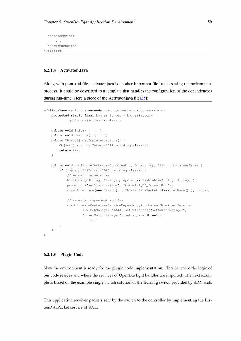
Chapter 6. OpenDaylight Application Development 59
<dependencies>
...
</dependencies>
</project>
6.2.1.4 Activator Java
Along with pom.xml file, activator.java is another important file in the setting up environment
process. It could be described as a template that handles the configuration of the dependencies
during run-time. Here a piece of the Activator.java file[25]:
public class Activator extends ComponentActivatorAbstractBase {
protected static final Logger logger = LoggerFactory
.getLogger(Activator.class);
public void init() { ... }
public void destroy() { ... }
public Object[] getImplementations() {
Object[] res = { TutorialL2Forwarding.class };
return res;
}
public void configureInstance(Component c, Object imp, String containerName) {
if (imp.equals(TutorialL2Forwarding.class)) {
// export the services
Dictionary<String, String> props = new Hashtable<String, String>();
props.put("salListenerName", "tutorial_L2_forwarding");
c.setInterface(new String[] { IListenDataPacket.class.getName() }, props);
// register dependent modules
c.add(createContainerServiceDependency(containerName).setService(
ISwitchManager.class).setCallbacks("setSwitchManager",
"unsetSwitchManager").setRequired(true));
...
}
}
}
6.2.1.5 Plugin Code
Now the environment is ready for the plugin code implementation. Here is where the logic of
our code resides and where the services of OpenDaylight bundles are imported. The next exam-
ple is based on the example single switch solution of the learning switch provided by SDN Hub.
This application receives packets sent by the switch to the controller by implementing the Ilis-
tenDataPacket service of SAL.

Chapter 6. OpenDaylight Application Development 60
public class TutorialL2Forwarding implements IListenDataPacket{
There are a few important methods that need to be highlighted to explain the process of the
development of this application example.
First of all, the method receiveDataPacket is invocated to check the MAC source and destination
addresses.
Then, the IListenDataPacket insterface calls this method when when a packet arrives at a node
withoud a pre-cached rule and the dataPacketService is used to forward a packet. This service
sends a packet out of a node-connector.
After forwarding and processing the packet, the other bundles are informed through PacketRe-
sult.CONSUME. The packets sended to the host 3 (ip=10.0.0.3) are ignored and the receiveDat-
aPacket method returns PacketResult.IGNORED.
The functions getSourceMACAddress() and getDestinationMACAddress() are used to parse
packet information.
Finally, the receiveDataPacket method needs to create an action list and consequently, match
them.
Here we can see the logic of our application:
@Override
public PacketResult receiveDataPacket(RawPacket inPkt) {
if (inPkt == null) {
return PacketResult.IGNORED;
}
// Use DataPacketService to decode the packet.
Packet pkt = this.dataPacketService.decodeDataPacket(inPkt);
//extract the incoming node (i.e., switch) and node-connector (i.e., switchport)
NodeConnector incoming_connector = inPkt.getIncomingNodeConnector();
Node incoming_node = incoming_connector.getNode();
if (pkt instanceof Ethernet) {
Object next = pkt.getPayload();
if (next instanceof IPv4) {
for ( int i = 0; i <= 1; i ++ ) {
IPv4 ipv4Pkt = (IPv4) next;
InetAddress dstIP =
intToInetAddress(ipv4Pkt.getDestinationAddress());
if (dstIP.equals(virtual_ip3)) {

Chapter 6. OpenDaylight Application Development 61
return PacketResult.IGNORED;
}
}
}
}
else return PacketResult.IGNORED;
byte[] srcMAC = ((Ethernet)pkt).getSourceMACAddress();
long srcMAC_val = BitBufferHelper.toNumber(srcMAC);
this.mac_to_port.put(srcMAC_val, incoming_connector);
byte[] dstMAC = ((Ethernet)pkt).getDestinationMACAddress();
long dstMAC_val = BitBufferHelper.toNumber(dstMAC);
NodeConnector outgoing_connector =
this.mac_to_port.get(dstMAC_val) ;
if (!outgoing_connector.equals(incoming_connector)) {
try {
RawPacket destPkt = new RawPacket(inPkt);
destPkt.setOutgoingNodeConnector(outgoing_connector);
this.dataPacketService.transmitDataPacket(destPkt);
} catch (ConstructionException e2) {
logger.warn("Could not create packet for PACKET_OUT");
return PacketResult.CONSUME;
}
}
Match match = new Match();
match.setField(MatchType.IN_PORT, incoming_connector);
match.setField(MatchType.DL_DST, dstMAC.clone());
match.setField(MatchType.DL_TYPE, EtherTypes.IPv4.shortValue());
match.setField(MatchType.IN_PORT, incoming_connector);
NodeConnector dst_connector;
// Do I know the destination MAC?
if ((dst_connector = this.mac_to_port.get(dstMAC_val)) != null) {
List<Action> actions = new ArrayList<Action>();
actions.add(new Output(dst_connector));
Flow f = new Flow(match, actions);
f.setIdleTimeout((short)10);
// Modify the flow on the network node
Status status = programmer.addFlow(incoming_node, f);
if (!status.isSuccess()) {
logger.warn("SDN Plugin failed to program the flow: {}.
The failure is: {}",
f, status.getDescription());
return PacketResult.IGNORED;
}
logger.info("Installed flow {} in node {}",

Chapter 6. OpenDaylight Application Development 62
f, incoming_node);
}
return PacketResult.CONSUME;
}
6.2.1.6 Evaluation test
Once the code has been developed, OpenDaylight OSGi framework compiles the build using
the Maven tool, which at the same time uses the POM file to do it.
After the code was written, the subsequent steps were followed to run the application:
• Run the following command to create the virtual network topology using Mininet and
Open vSwithc. This command emulates the desired topology (1 single switch with 3
hosts), that attemps to connect to a remote controller (OpenDaylight):
$ sudo mn –topo single,3 –mac –switch ovsk,protocols=OpenFlow13 –controller remote
• If we run the the command "pingall" , we can see that there is no reachability between
hosts as the switch does not have the intelligence to learn the MAC addresses of each host
and to forward traffic to the correct switch ports.
FIGURE 6.3: pingall unreachable
• To add intelligence to the switch, the application needs to be built and inserted into the
OSGi platform. As previously mentioned, it is achieved using maven tool. In a new ter-
minal, in the folder where the pom.xml file resides, run the following command:
$ mvn install -nsu

Chapter 6. OpenDaylight Application Development 63
• Run the controller itself to start the OSGi bundles installed as jar files in the plugins
directory. With the controller running and after all bundles are started, if we go back to
the Mininet terminal we can see that our application works as expected, hosts h1 and h2
"talk" to each other, but h3 remains outside the "conversation".
FIGURE 6.4: Results
6.2.2 MD-SAL Application Development
Thanks to YANG models, APIs are automatically generated and therefore MD-SAL which en-
tails an easier application development for the controller. Therefore, MD-SAL has been well
accepted by developers’ community.
However, it requires a deeper understanding. This section will attempt to briefly explain what
MD-SAL is and how to develop an MD-SAL application.
FIGURE 6.5: MD-SAL Software Architecture ViewSource: https://wiki.opendaylight.org MD-SAL App Tutorial

Chapter 6. OpenDaylight Application Development 64
Until MD-SAL appeared, the general overview presented consisted of protocol plugins in the
bottom, services plugins at the top and adaptations to these plugins in the middle. In MD-SAL,
the Service Abstraction Layer acts as a backbone of the system, where the plugins are plugged
into. That means, that the SAL is being just a plum connecting "consumers" and "providers", it
is an independent infrastructure.
Pre-requisites: to avoid future problems, it is necessary to have installed the Java 1.7.0 version
instead of the newer Java 1.8.0. Also, and Apache Maven version higher than 3.1.1 version is
required and Eclipse as IDE (see section 6.2.1.2).
6.2.2.1 POM XML file
As explained in section 6.2.1.3, the pom.xml file describes the dependencies to write against
the flow capable model, to compile the sample against different models (e.g. inventory, flow
services, flow base models) and also the MD-SAL APIs.
6.2.2.2 Activator Java
The bundle setup is already explained in section 6.2.1.3. For a better understanding the example
provided by SDN Hub MD-SAL "learning switch" is used
To start the application, the helper class AbstractBindingAwareConsumer is extended:
public class Activator extends AbstractBindingAwareConsumer implements AutoCloseable {
Then it implements the callback onSessionInitialized in order to be able to communicate with
the MD-SAL as a consumer. Now, any model or any API is exposed, only the existing ones are
being consumed:
public void onSessionInitialized(ConsumerContext session) {
The different dependencies need to be called: DataBroker, which provides access to other data
tree and is used to configure the flows and to look up into the operational interface. RpcService
is the packet processing service used to send the packets out. And the NotificationService,
used to subscribe for the notifications. Basically, when the PacketProcessingService is get, the
learningSwitchManagerMultiImpl class is started.
learningSwitch = new LearningSwitchManagerMultiImpl();
learningSwitch.setDataBroker(session.getSALService(DataBrokerService.class));

Chapter 6. OpenDaylight Application Development 65
learningSwitch.setPacketProcessingService(session.getRpcService
PacketProcessingService.class));
learningSwitch.setNotificationService(session.getSALService(NotificationService.class));
learningSwitch.start();
6.2.2.3 Plugin Code Overview
FIGURE 6.6: Building a Pluggin/ApplicationSource Os2014-md-sal-tutorial.pdf
MD-SAL uses the yang models. These models define the data structures, RPCs and notifi-
cations. Basically, plugins (or applications) are built for the controller while defining a new
model. There are a set of tools (e.g. Maven Plugin) that take the YANG model and generate
Java interfaces in the compile time. These Java interfaces represent the RPCs of the data struc-
tures. Summarizing, the developer has an API that is compiled into the Jar file to describe the
model. In the run-time, these jar files also contain the model and it is used for other MD-SAL
functions. The plugin must is developed against these generated APIs and against a set of MD-
SAL APIs (where services are registered).
Finally, maven is used to compile the plugin. It provides a jar file that needs to be deployed to
the controller to run the application.
6.2.2.4 Prepare the project
To get started on creating a MD-SAL application, maven project templates are used. These tem-
plates are known as maven archetype or MD-SAL-App-Simple.

Chapter 6. OpenDaylight Application Development 66
Run the Maven ArchetypeThe necessary steps to run the Maven Archetype are explained in the OpenDaylight wiki [26].
After executing the commands, some parameters will be asked: groupid, artifactid, version,
package and modelFields. At this point, the generation of the maven archetype is completed.
For more information abou Apache Maven Archetypes visit this site [27]
Finish Generation – Run the ’Generator’As maven archetypes are extremely limited in their capabilities, one more step is necessary. A
remainder of the template code is generated for the sample application. To do this we need to
make use of the "generate" folder which was created in the previous step.
Now, the project can be imported to the IDE.
What the MD-SAL Archetype ProvidesAs can be appreciated at the end of the execution of the "Run the Maven Archetype", 5 subfold-
ers were created under the <artifactId> folder.
• Consumer: how an application can be written, consuming the RPC (Remote Procedure
Calls) services provided with the provider bundle.
• Generate: helper folder used to add more capabilities to the maven archetypes.
• Model: sample yang file defining the "model".
• Provider: it sets up a service that implements any RPC already defined in the model’s
yang files.
• Web: application that allows defining customer REST APIs.
• Features: list of sample features to enable provider, consumer and web budles.
Additional Generation ParametersNaming the application and provide the Artifac and Group IDs are optionals, the command line
for these parameters are the followings:

Chapter 6. OpenDaylight Application Development 67
-DappName=<appNamePrefix>
-DgroupId=« Any group Id such as org.opendaylight.controller»
-DartifactId=«Any app name such as mdSalExample»
How to Remove Unneeded ProjectsFollow the next steps:
• Delete the project: rm –rf ’project’
• Modify the pom.xml in the root folder
• Remove the unneeded project from the "modules" section
• Remove the feature of the unneeded project, it is located in features/src/main/resources
directory
• Run ’mvn clean install’
Advanced Usage of the MD-SAL-App-Simple ArchetypeFor a better auto generation of a yang file there are advanced features of the MD-SAL-App-
Simple archetype. To do this you will make use of the "modelProperties" field.
When prompted during the interactive mode, or optionally using the ’-DmodelFields’ flag on
the command line, you can provide a JSON formatted list of fields that you want included in
your yang file.
6.2.2.5 POM XML File
As explained in section 6.1, the pom.xml file describes the dependencies to write against the
flow capable model, to compile the sample against different models (e.g. inventory, flow ser-
vices, flow base models) and also the MD-SAL APIs.
6.2.2.6 Karaf Feature
Apache Karaf is a small OSGi based runtime which provides a lightweight container for loading
different modules. In Apache Karaf, the application provisioning is an Apache Karaf "feature".

Chapter 6. OpenDaylight Application Development 68
Using karaf feature an application is described as a name, a version and a set of bundles. Op-
tionally, an application can be also described providing a description, a set of configurations or
configuration files and a set of dependency features.
When you install a feature, Apache Karaf installs all resources described in the feature. It
means that it will automatically resolves and installs all bundles, configurations, and dependency
features described in the feature. For further information about Karaf Features visit the following
site[28].
Define a Karaf FeatureKaraf features are defined in the src/main/resource/features.xml, located in the previously cre-
ated ‘ ’feature’ folder. For a better understanding, the md-sal application sample of SDN Hub
tutorial is used. In the following code snipped, we can see how the "thesis" feature is added.
<feature name=’odl-tesis’ version=’${project.version}’>
<feature version=’${yangtools.version}’>odl-yangtools-common</feature>
<feature version=’${yangtools.version}’>odl-yangtools-binding</feature>
<feature version=’${project.version}’>odl-mdsal-broker</feature>
<bundle>mvn:org.opendaylight.controller.samples/thesis/
${project.version}</bundle>
<bundle>mvn:org.opendaylight.controller.samples/thesis-consumer/
${project.version}</bundle>
<bundle>mvn:org.opendaylight.controller.samples/thesis-provider/
${project.version}</bundle>
<configfile finalname="${config.configfile.directory}/
${config.thesis.configfile}">
mvn:org.opendaylight.controller.samples/thesis-config/
${project.version}/xml/config</configfile>
</feature>
The following step for defining a Karaf Feature is, again, using the pom.xml contained in the
features project. A maven-resources-plugin is created to make the features.xml available outside
the jar in the maven repository.
<plugin>
<groupId>org.apache.maven.plugins</groupId>
<artifactId>maven-resources-plugin</artifactId>
<executions>
<execution>
<id>filter</id>
<goals>
<goal>resources</goal>
</goals>
<phase>generate-resources</phase>
</execution>
</executions>
</plugin>

Chapter 6. OpenDaylight Application Development 69
Once the features have been defined in the pom.xml, the maven Project can be built just running
the command:
$ mvn clean install
Feature DependencyWhile developing a feature, it may use (depend on) services such as RPCs or models. These
features must be also installed to maven repository and specified in the dependent’s definition.
<repository>mvn:org.opendaylight.yangtools/features-yangtools/
${ yangtools.version}/xml/features</repository>
<repository>mvn:org.opendaylight.controller/features-mdsal/
${controller.mdsal.version}/xml/features</repository>
Deploy the FeaturesWith the karaf distribution already running, execute the following command:
$ feature:repo-add mvn:<groupId>/features-<artifactId>/<version>/xml/features
Here [29] the installing instructions, how to run and how to add a feature.
After adding the feature, the next step consist in its installation:
$ feature:install ’feature_name’
To list the available features type:
$ feature:list
6.2.2.7 MD-SAL Model
YANG Modelling LanguageYANG (see section 6.1) is a data modeling language used by the Network Configuration Proto-
col (NETCONF).
In order to prepare the bundle, a first yang file defining data model is created under the name
thesis.yang. In this file the thesis attributes, container, RPC and notifications are defined. It is
located under src/main/yang folder and its general structure would be as follows:
module thesis {

Chapter 6. OpenDaylight Application Development 70
yang-version 1;
namespace "opendaylight:sample";
prefix thesis;
revision "2010-11-20" { description "Thesis module in progress.";
}
YANG Maven Plugin
To compile the thesis.yang file, the yang-maven-plugin[30] needs to be specified in the pom.xml.
<plugin>
<groupId>org.opendaylight.yangtools</groupId>
<artifactId>yang-maven-plugin</artifactId>
<executions>
<execution>
<goals>
<goal>generate-sources</goal>
</goals>
<configuration>
<yangFilesRootDir>src/main/yang</yangFilesRootDir>
<codeGenerators>
<generator>
<codeGeneratorClass>
org.opendaylight.yangtools.maven.sal.api.gen.plugin.CodeGeneratorImpl
</codeGeneratorClass>
<outputBaseDir>${salGeneratorPath}</outputBaseDir>
</generator>
</codeGenerators>
<inspectDependencies>true</inspectDependencies>
</configuration>
</execution>
</executions>
<dependencies>
<dependency>
<groupId>org.opendaylight.yangtools</groupId>
<artifactId>maven-sal-api-gen-plugin</artifactId>
<version>${yangtools.version}</version>
<type>jar</type>
</dependency>
</dependencies>
</plugin>
Generate the codeAfter running the command ’mvn clean install’ to build the project, the following classes will
be generated:
• Thesis: an interface that represents the thesis container with methods to obtain the leaf
node data.

Chapter 6. OpenDaylight Application Development 71
• ThesisData: The thesis container stores the data in the module.
• $YangModuleInfoImpl: information about the YANG module.
• $YangModelBindingProvider: private contructor of $YangModuleInfoImpl.
6.2.2.8 Implementing the Provider Plugin
This section aims to explain how to write the provider ‘thesis-provider-impl.yang’ to perform
RPC implementation and to add notification listeners. However, MD-SAL dependencies must
be included.
Service Dependency ConfigurationAgain, the yang-maven-plugin configured in the pom.xml is used to generate the Java code to
help with wiring into the config subsystem:
<plugin>
<groupId>org.apache.felix</groupId>
<artifactId>maven-bundle-plugin</artifactId>
<configuration>
<instructions>
<Export-Package>org.opendaylight.controller.config.yang.thesis_provider
</Export-Package>
<Import-Package>*</Import-Package>
</instructions>
</configuration>
</plugin>
<plugin>
<groupId>org.opendaylight.yangtools</groupId>
<artifactId>yang-maven-plugin</artifactId>
<executions>
<execution>
<id>config</id>
<goals>
<goal>generate-sources</goal>
</goals>
<configuration>
<codeGenerators>
<generator>
<codeGeneratorClass>
org.opendaylight.controller.config.yangjmxgenerator.plugin.JMXGenerator
</codeGeneratorClass>
<outputBaseDir>${jmxGeneratorPath}</outputBaseDir>
<additionalConfiguration>
<namespaceToPackage1>
urn:opendaylight:params:xml:ns:yang:controller==
org.opendaylight.controller.config.yang
</namespaceToPackage1>
</additionalConfiguration>

Chapter 6. OpenDaylight Application Development 72
</generator>
<generator>
<codeGeneratorClass>
org.opendaylight.yangtools.maven.sal.api.gen.plugin.CodeGeneratorImpl
</codeGeneratorClass>
<outputBaseDir>${salGeneratorPath}</outputBaseDir>
</generator>
</codeGenerators>
<inspectDependencies>true</inspectDependencies>
</configuration>
</execution>
</executions>
</plugin>
Config Subsystem Dependency ConfigurationThe thesis-provider-imple.yang file is used by the code generator to create Java classes. This
listing shows the declaration of dependency on the three Config Subsystem Services:
// This is the definition of the service implementation as a module identity
identity thesis-provider-impl {
base config:module-type;
// Specifies the prefix for generated java classes.
config:java-name-prefix ThesisProvider;
}
// Augments the ’configuration’ choice node under modules/module.
augment "/config:modules/config:module/config:configuration" {
case thesis-provider-impl {
when "/config:modules/config:module/config:type = thesis-provider-impl’";
//Wires dependent services into this class - RPC registry service
container rpc-registry {
uses config:service-ref {
refine type {
mandatory true;
config:required-identity mdsal:binding-rpc-registry;
}
}
}
container notification-service {
uses config:service-ref {
refine type {
mandatory true;
config:required-identity mdsal:binding-notification-service;
}
}
}
//Wires in the data-broker service
container data-broker {

Chapter 6. OpenDaylight Application Development 73
uses config:service-ref {
refine type {
mandatory false;
config:required-identity mdsal:binding-async-data-broker;
}
}
}
}
}
}
Compiling the project, two files will be generated under the directory src/main/java:
• ThesisProviderModule - concrete class whose createInstance() method provides the Open-
daylightThesis instance.
• ThesisProviderModuleFactory - concrete class, instantiated internally by MD-SAL which
creates ThesisProviderModule instances.
6.2.2.9 How Karaf knows about the Config Subsystem Dependency
This process is similar to the ’features.xml’ description section 6.2.2.6. The Config Subsystem
Services are also contained in xml-files. Karaf use them to initialize a module in the config
subsystem and make it available for use in a controller environment.
In configuration/initia/03-thesis-sample.xml file:
<snapshot>
<required-capabilities>
...
</required-capabilities>
<configuration>
<data xmlns="urn:ietf:params:xml:ns:netconf:base:1.0">
<modules xmlns=
"urn:opendaylight:params:xml:ns:yang:controller:config">
<module>
<type xmlns:prefix=
"urn:opendaylight:params:xml:ns:yang:controller:config:
thesis-provider:impl">prefix:thesis-provider-impl</type>
<name>thesis-provider-impl</name>
</module>
</modules>
</configuration>
</snapshot>
Maven PluginNow that a maven plugin is added in the pom.xml provider, this file can be included in the
features.xml file.

Chapter 6. OpenDaylight Application Development 74
<plugin>
<groupId>org.codehaus.mojo</groupId>
<artifactId>build-helper-maven-plugin</artifactId>
<executions>
<execution>
<id>attach-artifacts</id>
<goals>
<goal>attach-artifact</goal>
</goals>
<phase>package</phase>
<configuration>
<artifacts>
<artifact>
<file>
${project.build.directory}/classes/initial/03-thesis-sample.xml
</file>
<type>xml</type>
<classifier>config</classifier>
</artifact>
</artifacts>
</configuration>
</execution>
</executions>
</plugin>
6.2.2.10 Implementing Consumer Plugin
The consumer plugin only need to call the RPC implemented by the provider. The developing
process is the same as the explained for the Provider Plugin. This is declared in its thesis-
consumer-impl.yang. The YANG file is the following:
//augments the configuration,
augment "/config:modules/config:module/config:configuration" {
case thesis-provider-impl {
when "/config:modules/config:module/config:type = thesis-provider-impl’";
...
//Wires dependent services into this class - RPC registry service
container rpc-registry {
uses config:service-ref {
refine type {
mandatory true;
config:required-identity mdsal:binding-rpc-registry;
}
}
}
}
}

Chapter 6. OpenDaylight Application Development 75
Generate the CodeThe last step to do is adding the yang-maven-plugin in the pom.xml file.
When the project is compiled ($mvn clean install), the module code is generated under the name
ThesisConsumerModule.java and it provides the entry point for our module.
public AutoCloseable createInstance(){
ThesisService service = getRpcRegistryDependency().getRpcService(thesisService.class);
final ThesisConsumerImpl consumerImpl = new ThesisConsumerImpl(service);
This method is called when the plugin is loaded to karaf.
OpenDaylight Controller project provides a toaster sample explaining step-by-step how to de-
velop a MD-SAL application [31]
6.3 Writing an Application using RESTful APIs
The Service Abstraction Layer provides an environment to pass messages between NortBound
to Southbound interface. As described in section 6.2, there are two different SAL concepts,
AD-SAL and MD-SAL, used to develop an application using an OSGi interface. When writing
an application using REST APIs, it may be said that there are also two types. Although the way
AD-SAL and MD-SAL provide REST API is really similar, their usage and theis URL address
are different.
With AD-SAL the REST APIs is hardcoded in the source code and the requests are listened
from port 8080, whereas in MD-SAL the automatic generation of the REST API makes the API
generation process much more flexible and it uses the port 8181. However, the additional model
generation increases the complexity.
In the following sections, the topology single,3 (1 switch – 3 hosts) will be used. Again, Mininet
is the tool used to create the topology:
$ sudo mn –topo single,3 –mac –switch ovsk,protocols=OpenFlow13 –controller remote
Also, the controller must be running. To do this, download and install Helium-SR3 release[32]
and execute the following commands:
$ cd distribution-karaf-0.2.3-Helium-SR3 $ ./bin/karaf

Chapter 6. OpenDaylight Application Development 76
With the controller running, there are few required karaf library:
$ feature:install odl-openflowplugin-all odl-ovsdb-all odl-adsal-northbound odl-adsal-compatibility-
all odl-adsal-all odl-adsal-core odl-adsal-networkconfiguratoin odl-adsa-connection odl-adsal-
clustering odl-adsal-configuration odl-adsal-thirdparty odl-nsf-all
6.3.1 AD-SAL REST API
Now that the controller is running and our topology is created we can get Data through REST
Requests using cURL.
Note: a packet has been sent from h1 to h2 ($ h1 ping h2 –c1)
• GET Network Topology (See Figure 6.7): http://localhost:8080/controller/nb/v2/topology/default
(user:admin password:admin)
• GET Flow statistics (See Figure 6.8): http://localhost:8080/controller/nb/v2/statistics/default/flow
• GET Switches (See Figure 6.9): http://localhost:8080/controller/nb/v2/switchmanager/default/nodes
FIGURE 6.7: GET Network Topology AD-SAL

Chapter 6. OpenDaylight Application Development 77
FIGURE 6.8: GET Flow Statistics AD-SAL
FIGURE 6.9: GET Switches AD-SAL
6.3.2 MD-SAL RESTCONF API
RESTCONF protocol, as said before, listens to port 8181 for HTTP requests. It operates a con-
ceptual database modeled with YANG language. There are two types of access to the data stores
via the controller: Config and Operational, containing data inserted by controller and other data
inserted via network, respectively.
• Through this URL http://localhost:8181/apidoc/explorer/index.html RESTCONF can be
accessed. The following figure shows the result:
Here, actions such as GET, PUT and DELETE actions are available.

Chapter 6. OpenDaylight Application Development 78
FIGURE 6.10: RESTCONF apidoc
• GET Data: http://localhost:8181/restconf/operational/opendaylight-inventory:nodes
FIGURE 6.11: Get Data RESTCONF
6.3.3 How to add a flow
For a better understanding the same scenario used for AD-SAL explanation will be used (see
section 6.2.1), with the difference that this time, REST APIs will be used:
6.3.3.1 Plugin Code
To add a flow to our switches it can be written in different languages, in this case it is written in
XML. In this example the packets from the host3 will be dropped:

Chapter 6. OpenDaylight Application Development 79
<?xml version="1.0" encoding="UTF-8" standalone="no"?>
<flow xmlns="urn:opendaylight:flow:inventory">
<strict>false</strict>
<instructions>
<instruction>
<order>0</order>
<apply-actions>
<action>
<order>0</order>
<drop-action/>
</action>
</apply-actions>
</instruction>
</instructions>
<table_id>0</table_id>
<id>1</id>
<cookie_mask>255</cookie_mask>
<installHw>false</installHw>
<match>
<ethernet-source>
<address>00:00:00:00:00:03</address>
<ethernet-source>
</match>
<cookie>3</cookie>
<flow-name>FooXf3</flow-name>
<priority>15</priority>
<barrier>false</barrier>
</flow>
6.3.4 Test the Code
Before testing the code, the current flow tables installed in the switch can be checked through
the following commands in Mininet:
$ pingall $ sh ovs-ofctl -O OpenFlow13 dump-flows s1
As shown in the Figure, a number of flows have installed when making the ping.
Now it is time to add the flow. The xml file is called “test4”. To do this, execute the following
command:
$ curl -X PUT -d @test4 -H "Content-Type: application/xml" -H "Accept: application/xml"
–user admin:admin http://127.0.0.1:8181/restconf/config/opendaylight-inventory:nodes/node/
openflow:1/table/0/flow/1
If we check now the flow tables and "pingall" we can see that our flow has been added and
host3 does not have any communication with host1 and host2, the same results as the example

Chapter 6. OpenDaylight Application Development 80
FIGURE 6.12: Flow tables before adding flow
FIGURE 6.13: PUT Flow
in AD-SAL writing application:
FIGURE 6.14: Results

Chapter 6. OpenDaylight Application Development 81
In case that we wish GET or DELETE the added flow, execute in the console the following
commands:
$ curl -X GET -d @test4 -H "Content-Type: application/xml" -H "Accept: application/xml"
–user admin:admin http://127.0.0.1:8181/restconf/config/opendaylight-inventory:nodes/node/
openflow:1/table/0/flow/1
$ curl -X DELETE -d @test4 -H "Content-Type: application/xml" -H "Accept: application/xml"
–user admin:admin http://127.0.0.1:8181/restconf/config/opendaylight-inventory:nodes/node/
openflow:1/table/0/flow/1

Chapter 7
Conclusions and Future Work
In this thesis, the vision of future networks as well as its challenges has been displayed. Fur-
thermore, the necessary information regarding the OpenDaylight Controller project is presented
to guide the reader throughout the entire learning process of this subject.
In order to properly understand the different processes of writing an OpenDaylight application,
important concepts such as Software Defined Networking (SDN), Network Function Virtualiza-
tion (NFV), Cloud Computing or the OpenFlow protocol have been defined and studied. Also,
Mininet has been presented and used as a network emulator.
Chapters 5 and 6, the core of the thesis, presented the OpenDaylight Controller project and the
differing ways to work with it:
• Bundles that are installed in the OSGi framework, located beside the driver, run locally
(AD-SAL and MD-SAL)
• REST instructions remotely executed.
A test case called "Solving a DoS Attack" is described, where a malicious host is launching a
DoS attack to consume the SDN resources of the network. AD-SAL and REST API methods
were used to create an application, which drops the packets coming from the attacker.
Having compared the three methods of writing an application for this controller, it is easy to see
that the REST APIs method is far easier, faster and language independent. However, this method
is unable to install reactive bundles and it does not provide the same flexibility and performance
as the OSGi interfaces.
82

Bibliography 83
The two existing options available when programming bundles were explained. These are called
API Driven SAL and Model Driven SAL. While AD-SAL is compiled through the code inside
the interface, MD-SAL is more abstract and is compiled by applying models. This is a more
innovative alternative and the community has already migrated from AD-SAL to MD-SAL. For
that reason, MD-SAL is generally less documented, with fewer examples to help developers to
understand and clarify its process.
At this moment in time, the OpenDaylight project is still under research. Potential future work
might be to deploy and recreate the proposed examples into a physical network and study the
MD-SAL architecture in further depth. This thesis can serve as a basis and an initiation for
future OpenDaylight developers who wish to be part of the fascinating world of 5th generation
networks.

Bibliography
[1] Terry Nakajima. "Introduction to OpenDaylight: An Open Source Community around
SDN". May 2013)
[2] IEEE Cloud Computing: http://cloudcomputing.ieee.org//
[3] ONF: https://www.opennetworking.org/
[4] http://www.etsi.org/technologies-clusters/technologies/nfv
[5] http://www.etsi.org/technologies-clusters/technologies/nfv
[6] https://www.openstack.org/
[7] https://wiki.opendaylight.org/view/OpenStack_and_OpenDaylight
[8] http://blog.flux7.com/blogs/openstack/tutorial-how-to-install-multi-nodes-in-openstack
[9] https://www.opennetworking.org/sdn-resources/sdn-definition
[10] http://vlkan.com/blog/post/2013/07/31/openflow-controllers/
[11] NOX. http://www.noxrepo.org/nox/about-nox/
[12] POX. http://www.noxrepo.org/pox/about-pox/
[13] ERICKSON D. "The Beacon OpenFlow Controller". ACM 2013.
[14] Floodlight. http://www.projectfloodlight.org/
[15] http://www.osgi.org/Technology/WhatIsOSGi
[16] https://www.opennetworking.org/Openflow
[17] http://mininet.org/overview/
[18] Repository: https://github.com/mininet/mininet/tree/master/examples
[19] https://wiki.opendaylight.org/view/Project_list
[20] http://www.opendaylight.org/project/technicaloverview
84

Bibliography 85
[21] https://wiki.opendaylight.org/view/OpenDaylight_Controller:Main
[22] http://sdnhub.org/tutorials/opendaylight/
[23] https://wiki.opendaylight.org/view/OpenDaylight_Controller:Eclipse_CLI_Setup
[24] https://github.com/sdnhub/SDNHub_Opendaylight_Tutorial/blob/master/commons/
parent/pom.xml
[25] https://github.com/sdnhub/SDNHub_Opendaylight_Tutorial/blob/master/
adsal_L2_forwarding/src/main/java/org/opendaylight/tutorial/tutorial_L2_forwarding/
internal/Activator.java
[26] https://maven.apache.org/guides/introduction/introduction-to-archetypes.html
[27] http://maven.apache.org/guides/introduction/introduction-to-archetypes.html
[28] http://karaf.apache.org/manual/latest/users-guide/provisioning.html
[29] https://wiki.opendaylight.org/view/OpenDaylight_DLUX:DLUX_Karaf_Feature
[30] https://wiki.opendaylight.org/view/YANG_Tools:User_Guide
[31] https://wiki.opendaylight.org/view/OpenDaylight_Controller:MD-SAL:Toaster_Step-By-
Step
[32] http://www.opendaylight.org/software/downloads