next generation dc to dc booster battery charger
TRANSCRIPT

Features Include:• 3-Stage 12V Booster Battery Charger• Output Current : 80A Max with optional kit. 40A Max standard wiring.• Selectable output voltages for Lithium, Sealed Lead Acid or Vented Lead Acid • Over Current and Temperature protections for extra product reliability.
• Precise under voltage protection : No need for external isolator. • Remote LED indication for battery charge status. • Very low standby current: <3mA• Optional Start Assist and Boost Charge features.
Next Generation DC to DC Booster Battery Charger
12VDC to 12VDC 40AOperating Instructions
Please read these instructions before use
The BTDC40 is able to utilize up to 80A charging to the auxiliary battery using our new boost mode (Kit Sold Separately) and 40A when wired with a standard configuration. This is all still acheived in the same extremely compact package (373cm³) while still boasting all the features of a booster battery charger in a weather, dust and vibration resistant package.
TECHNICAL SPECS - BTDBMInput voltage 5v to 17v
Current draw 35mA running - 0.4mA standby
Accuracy 50mV
Dimensions L X W X H 59mm x 44mm x 21mm
Connections 1.5M 4-Core Cable

Next Generation DC to DC Booster Battery Charger
12VDC to 12VDC 40AOperating Instructions
Please read these instructions before use
Operational ParametersMaximum Charge Current (with Boost Kit) 80 AmpsMaximum Charge Current (Standard Wiring) 40 AmpsInput Operating Voltage Range 11VDC to 16VDCMaximum Charge Voltage for Flooded Cell 14.5VMaximum Charge Voltage for Lithium 14.8VMaximum Charge Voltage for AGM/GEL 14.3VFloat Voltage 13.5VLithium Maintenance Charge 13.9VStand by Current 0.003AMinimum Input Startup Voltage 12VMaximum Operating Temperature 70°CDimensions 162mm x 71.5mm x 32.2mm
Important Notes:• Before installation the user shall determine the suitability of the product to ensure correct application.• Check with your battery manufacturer for the suitability of the charger for your installation.• Where Lithium battery banks are involved ensure your BMS system is compatible with our charger.• A large spark can sometimes be generated during connection, due to the current required to charge the capacitors in the charger.• Do not short output when enabled and operational as this may cause damage to the unit.•Yellow wire must only be used with optional solenoid otherwise it should be left unconnected and isolated.
1. Disconnect the battery supply.2. The following connection sequence is to be followed: Ground (BLACK), Input (RED), Output (BROWN),LED (GREEN), Chemistry/Output Selection (ORANGE), Control (BLUE). 3. The unit is protected from weather and dust but do not pressure wash or mount to areas that will be submerged. Avoid locations such as fuel lines or where external heat is produced e.g. exhaust system or where the batteries are located.4. Chose a position with good ventilation where air can pass freely around the unit.5. Ensure the unit is protected from sources of contamination e.g. oil, grease and dust.6. 7. If optional solenoid is used we recommend mounting it close to the charger as per wiring diagram.
Installation:
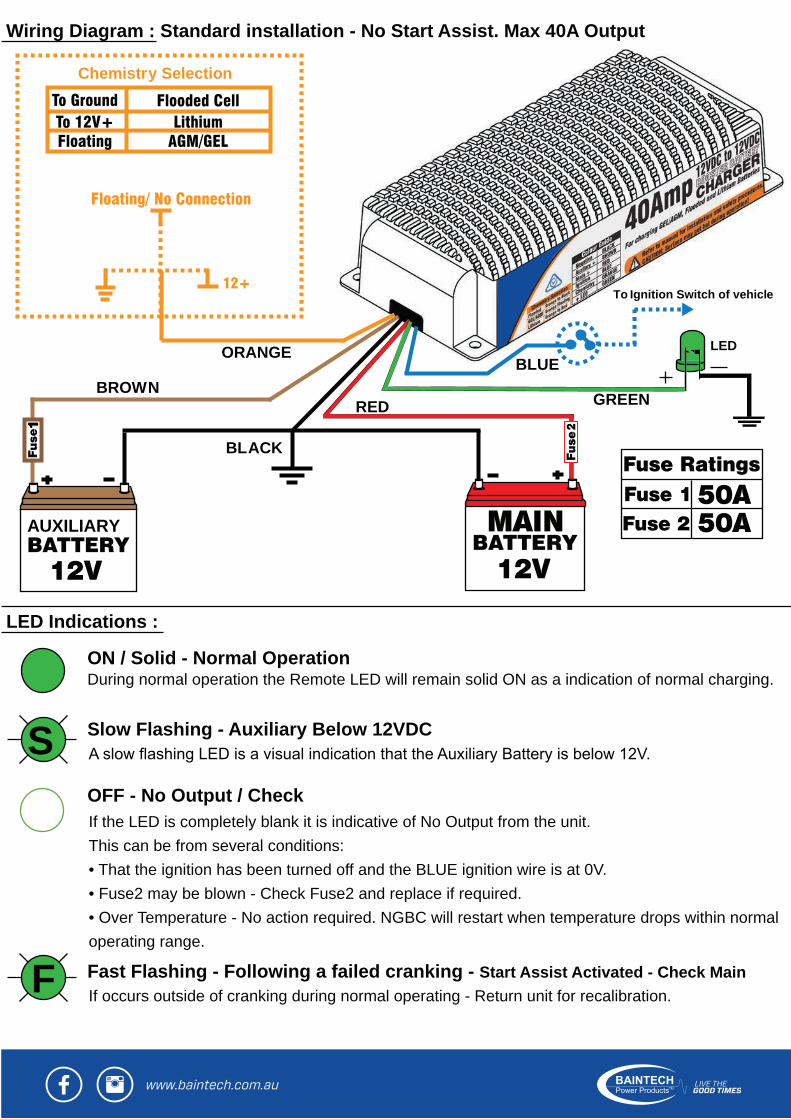
Wiring Diagram : Standard installation - No Start Assist. Max 40A Output
LED Indications :
To Ignition Switch of vehicle
RED GREEN
BLACK
BROWN
ORANGEBLUE
Chemistry Selection
LED
OFF - No Output / Check
Slow Flashing - Auxiliary Below 12VDC
Fast Flashing - Following a failed cranking - Start Assist Activated - Check Main
ON / Solid - Normal Operation During normal operation the Remote LED will remain solid ON as a indication of normal charging.
If occurs outside of cranking during normal operating - Return unit for recalibration.
If the LED is completely blank it is indicative of No Output from the unit. This can be from several conditions:• That the ignition has been turned off and the BLUE ignition wire is at 0V. • Fuse2 may be blown - Check Fuse2 and replace if required. • Over Temperature - No action required. NGBC will restart when temperature drops within normal operating range.
AUXILIARY
S
F

Wiring Diagram - For Optional Start Assist- Boost upto 80A Output :For BLUE, ORANGE and GREEN Wires refer to previous wiring diagramNOTE: 100A or greater rated cabling must be used between solenoid and batteries.
Optional Start Assist and Boost Charge:
The optional Solenoid Kit (Part No. BTDC40KITprovide the features of the unique Start Assist and Boost Charge modes. Start Assist:With the solenoid connected it enables the BTDC40 to automatically provide assistance from the Auxiliary Battery on starting of the vehicle. Provided the Auxiliary Battery is charged. Following a failed cranking attempt due to low main battery charge- Release the key so it returns to “ON” position, do not bring it to the “OFF” or “ACC” position. Now within a couple of seconds try cranking
Boost Charge:With the addition of the solenoid boost charge will allow up to 80Acharging conditions. This initial Boost Charge Mode reverts automatically to normal charging once the auxiliary recovers from deep discharge.
100A> Rated Cable
SignalWire
100A> Rated Cable
Kit Sold Separately)
All products manufactured or supplied by BAINTECH to a person de�ned as a “Consumer” come with guarantees that cannot be excluded under the Australian Consumer Law. You are entitled to a replacement or refund for a major failure and compensation for any other reasonably foreseeable loss or damage. You are also entitled to have the goods repaired or replaced if the goods fail to be of acceptable quality and the failure does not amount to a major failure. For full warranty terms visit - https://www.baintech.com.au/contact-us/warranty-2