2 ch dc charger - graupner · pdf file2 ch dc charger. 3 4 - contents - ... use of problem and...
TRANSCRIPT
OPERATING INSTRUCTIONPrior to use, please read this manual thoroughly. Keep this manual in a convenient place for quick and easy reference.
2 CH DC CHARGER
3 4
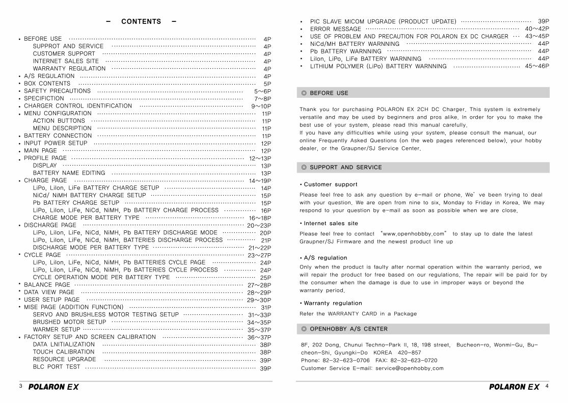
- CONTENTS -
BEFORE USE SUPPROT AND SERVICE CUSTOMER SUPPORT INTERNET SALES SITE WARRANTY REGULATIONA/S REGULATIONBOX CONTENTS SAFETY PRECAUTIONS SPECIFICTIONCHARGER CONTROL IDENTIFICATIONMENU CONFIGURATION ACTION BUTTONS MENU DESCRIPTIONBATTERY CONNECTIONINPUT POWER SETUP MAIN PAGEPROFILE PAGE DISPLAY BATTERY NAME EDITINGCHARGE PAGE LiPo, LiIon, LiFe BATTERY CHARGE SETUP NiCd/ NiMH BATTERY CHARGE SETUP Pb BATTERY CHARGE SETUP LiPo, Lilon, LiFe, NiCd, NiMH, Pb BATTERY CHARGE PROCESS CHARGE MODE PER BATTERY TYPEDISCHARGE PAGE LiPo, LiIon, LiFe, NiCd, NiMH, Pb BATTERY DISCHARGE MODE LiPo, Lilon, LiFe, NiCd, NiMH, BATTERIES DISCHARGE PROCESS DISCHARGE MODE PER BATTERY TYPECYCLE PAGE LiPo, Lilon, LiFe, NiCd, NiMH, Pb BATTERIES CYCLE PAGE LiPo, Lilon, LiFe, NiCd, NiMH, Pb BATTERIES CYCLE PROCESS CYCLE OPERATION MODE PER BATTERY TYPEBALANCE PAGEDATA VIEW PAGEUSER SETUP PAGEMISE PAGE (ADDITION FUNCTION) SERVO AND BRUSHLESS MOTOR TESTING SETUP BRUSHED MOTOR SETUP WARMER SETUPFACTORY SETUP AND SCREEN CALIBRATION DATA LNITIALIZATION TOUCH CALIBRATION RESOURCE UPGRADE BLC PORT TEST
4P4P4P4P4P4P5P
5~6P7~8P
9~10P11P11P11P11P12P12P
12~13P13P13P
14~19P14P15P15P16P
16~18P20~23P
20P21P
21~22P23~27P
24P24P25P
27~28P28~29P29~30P
31P31~33P34~35P35~37P36~37P
38P38P
39P
39P
◎ BEFORE USE
◎ SUPPORT AND SERVICE
◎ OPENHOBBY A/S CENTER
8F, 202 Dong, Chunui Techno-Park II, 18, 198 street, Bucheon-ro, Wonmi-Gu, Bu-
cheon-Shi, Gyungki-Do KOREA 420-857
Phone: 82-32-623-0706 FAX: 82-32-623-0720
Customer Service E-mail: [email protected]
Internet sales site
Please feel free to contact “www.openhobbby.com” to stay up to date the latest
Graupner/SJ Firmware and the newest product line up
Customer support
Please feel free to ask any question by e-mail or phone. We’ve been trying to deal
with your question. We are open from nine to six, Monday to Friday in Korea. We may
respond to your question by e-mail as soon as possible when we are close.
Thank you for purchasing POLARON EX 2CH DC Charger. This system is extremely
versatile and may be used by beginners and pros alike. In order for you to make the
best use of your system, please read this manual carefully.
If you have any difficulties while using your system, please consult the manual, our
online Frequently Asked Questions (on the web pages referenced below), your hobby
dealer, or the Graupner/SJ Service Center.
A/S regulation
Only when the product is faulty after normal operation within the warranty period, we
will repair the product for free based on our regulations. The repair will be paid for by
the consumer when the damage is due to use in improper ways or beyond the
warranty period.
Warranty regulation
Refer the WARRANTY CARD in a Package
PIC SLAVE MICOM UPGRADE (PRODUCT UPDATE)ERROR MESSAGEUSE OF PROBLEM AND PRECAUTION FOR POLARON EX DC CHARGERNiCd/MH BATTERY WARNNINGPb BATTERY WARNNINGLilon, LiPo, LiFe BATTERY WARNNINGLITHIUM POLYMER (LiPo) BATTERY WARNNING
39P40~42P43~45P
44P44P44P
45~46P
5 6
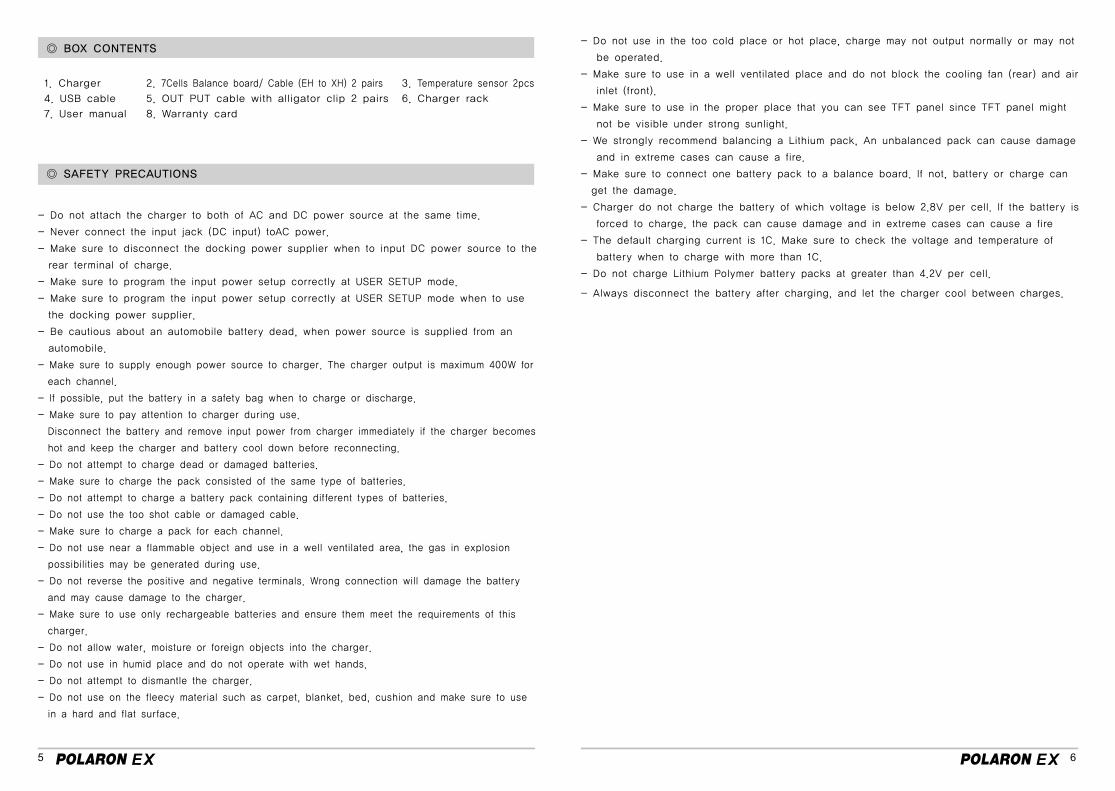
◎ BOX CONTENTS
◎ SAFETY PRECAUTIONS
- Do not attach the charger to both of AC and DC power source at the same time.
- Never connect the input jack (DC input) toAC power.
- Make sure to disconnect the docking power supplier when to input DC power source to the
rear terminal of charge.
- Make sure to program the input power setup correctly at USER SETUP mode.
- Make sure to program the input power setup correctly at USER SETUP mode when to use
the docking power supplier.
- Be cautious about an automobile battery dead, when power source is supplied from an
automobile.
- Make sure to supply enough power source to charger. The charger output is maximum 400W for
each channel.
- If possible, put the battery in a safety bag when to charge or discharge.
- Make sure to pay attention to charger during use.
Disconnect the battery and remove input power from charger immediately if the charger becomes
hot and keep the charger and battery cool down before reconnecting.
- Do not attempt to charge dead or damaged batteries.
- Make sure to charge the pack consisted of the same type of batteries.
- Do not attempt to charge a battery pack containing different types of batteries.
- Do not use the too shot cable or damaged cable.
- Make sure to charge a pack for each channel.
- Do not use near a flammable object and use in a well ventilated area, the gas in explosion
possibilities may be generated during use.
- Do not reverse the positive and negative terminals. Wrong connection will damage the battery
and may cause damage to the charger.
- Make sure to use only rechargeable batteries and ensure them meet the requirements of this
charger.
- Do not allow water, moisture or foreign objects into the charger.
- Do not use in humid place and do not operate with wet hands.
- Do not attempt to dismantle the charger.
- Do not use on the fleecy material such as carpet, blanket, bed, cushion and make sure to use
in a hard and flat surface.
- Do not use in the too cold place or hot place, charge may not output normally or may not
be operated.
- Make sure to use in a well ventilated place and do not block the cooling fan (rear) and air
inlet (front).
- Make sure to use in the proper place that you can see TFT panel since TFT panel might
not be visible under strong sunlight.
- We strongly recommend balancing a Lithium pack, An unbalanced pack can cause damage
and in extreme cases can cause a fire.
- Make sure to connect one battery pack to a balance board. If not, battery or charge can
get the damage.
- Charger do not charge the battery of which voltage is below 2.8V per cell. If the battery is
forced to charge, the pack can cause damage and in extreme cases can cause a fire
- The default charging current is 1C. Make sure to check the voltage and temperature of
battery when to charge with more than 1C.
- Do not charge Lithium Polymer battery packs at greater than 4.2V per cell.
- Always disconnect the battery after charging, and let the charger cool between charges.
1. Charger
4. USB cable
7. User manual
3. Temperature sensor 2pcs
6. Charger rack
2. 7Cells Balance board/ Cable (EH to XH) 2 pairs
5. OUT PUT cable with alligator clip 2 pairs
8. Warranty card
7 8
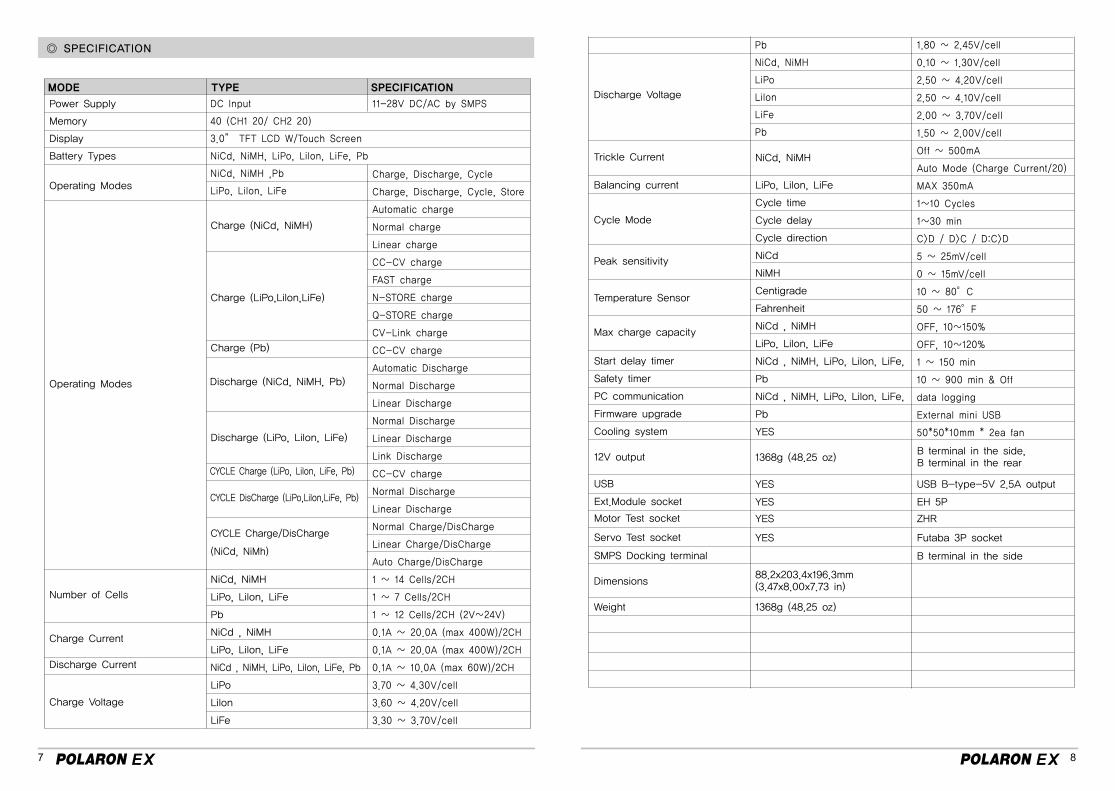
◎ SPECIFICATION
MODE TYPE SPECIFICATION
Power Supply
Memory
Display
Battery Types
Discharge Voltage
Operating Modes
Trickle Current
Balancing current
Operating Modes
Cycle Mode
Peak sensitivity
Temperature Sensor
Max charge capacity
Number of Cells
12V output
USB
Ext.Module socket
Motor Test socket
Servo Test socket
SMPS Docking terminal
Start delay timer
Safety timer
PC communication
Firmware upgrade
Cooling system
Charge Current
Dimensions
Discharge Current
Weight 1368g (48.25 oz)
1368g (48.25 oz)
YES
YES
YES
YES
88.2x203.4x196.3mm (3.47x8.00x7.73 in)
USB B-type-5V 2.5A output
EH 5P
ZHR
Futaba 3P socket
B terminal in the side
B terminal in the side,B terminal in the rear
Charge Voltage
Charge (NiCd, NiMH)
NiCd, NiMH
LiPo, LiIon, LiFe
Cycle time
Cycle delay
Cycle direction
NiCd
NiMH
Centigrade
Fahrenheit
NiCd , NiMH
LiPo, LiIon, LiFe
NiCd , NiMH, LiPo, LiIon, LiFe,
Pb
NiCd , NiMH, LiPo, LiIon, LiFe,
Pb
YES
Charge (LiPo,LiIon,LiFe)
Charge (Pb)
NiCd, NiMH
LiPo, LiIon, LiFe
Pb
NiCd , NiMH
LiPo, LiIon, LiFe
NiCd , NiMH, LiPo, LiIon, LiFe, Pb
LiPo
LiIon
LiFe
Discharge (NiCd, NiMH, Pb)
Discharge (LiPo, LiIon, LiFe)
CYCLE Charge (LiPo, LiIon, LiFe, Pb)
CYCLE Charge/DisCharge
(NiCd, NiMh)
CYCLE DisCharge (LiPo,LiIon,LiFe, Pb)
11-28V DC/AC by SMPS
Charge, Discharge, Cycle
Charge, Discharge, Cycle, Store
Automatic charge
Normal charge
Linear charge
CC-CV charge
FAST charge
N-STORE charge
Q-STORE charge
CV-Link charge
CC-CV charge
Automatic Discharge
Normal Discharge
Linear Discharge
Normal Discharge
Linear Discharge
Link Discharge
CC-CV charge
Normal Discharge
Linear Discharge
Normal Charge/DisCharge
Linear Charge/DisCharge
Auto Charge/DisCharge
1 ~ 14 Cells/2CH
1 ~ 7 Cells/2CH
1 ~ 12 Cells/2CH (2V~24V)
0.1A ~ 20.0A (max 400W)/2CH
0.1A ~ 20.0A (max 400W)/2CH
0.1A ~ 10.0A (max 60W)/2CH
3.70 ~ 4.30V/cell
3.60 ~ 4.20V/cell
3.30 ~ 3.70V/cell
1.80 ~ 2.45V/cell
0.10 ~ 1.30V/cell
2.50 ~ 4.20V/cell
2.50 ~ 4.10V/cell
2.00 ~ 3.70V/cell
1.50 ~ 2.00V/cell
Off ~ 500mA
Auto Mode (Charge Current/20)
MAX 350mA
1~10 Cycles
1~30 min
C>D / D>C / D:C>D
5 ~ 25mV/cell
0 ~ 15mV/cell
10 ~ 80°C
50 ~ 176°F
OFF, 10~150%
OFF, 10~120%
1 ~ 150 min
10 ~ 900 min & Off
data logging
External mini USB
50*50*10mm * 2ea fan
DC Input
40 (CH1 20/ CH2 20)
3.0” TFT LCD W/Touch Screen
NiCd, NiMH, LiPo, LiIon, LiFe, Pb
NiCd, NiMH ,Pb
LiPo, LiIon, LiFe
Pb
NiCd, NiMH
LiPo
LiIon
LiFe
Pb
9 10
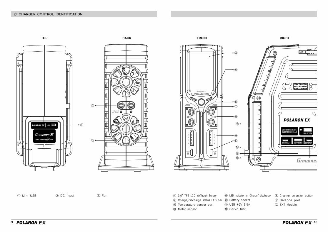
◎ CHARGER CONTROL IDENTIFICATION
① Mini USB ④ 3.0”TFT LCD W/Touch Screen
⑦ Charge/discharge status LED bar
⑩ Temperature sensor port
⑬ Motor sensor
② DC Input ⑤ LED Indicator for Charge/ discharge
⑧ Battery socket
⑪ USB +5V 2.5A
⑭ Servo test
③ Fan ⑥ Channel selection button
⑨ Balance port
⑫ EXT Module
①
④
⑤
⑥
⑦
⑧
⑪
⑫
⑬
⑭
⑨
⑩
②
③
TOP FRONTBACK RIGHT
11 12
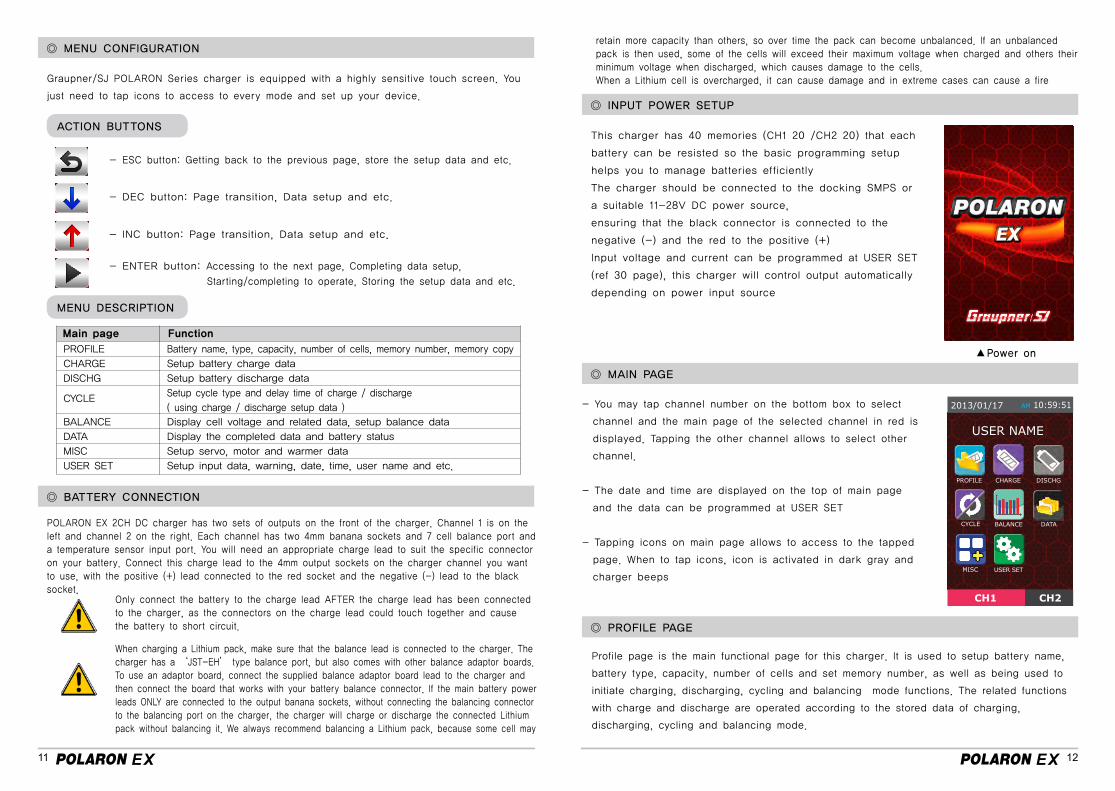
◎ MENU CONFIGURATION
◎ INPUT POWER SETUP
◎ MAIN PAGE
◎ PROFILE PAGE
◎ BATTERY CONNECTION
Graupner/SJ POLARON Series charger is equipped with a highly sensitive touch screen. You
just need to tap icons to access to every mode and set up your device.
This charger has 40 memories (CH1 20 /CH2 20) that each
battery can be resisted so the basic programming setup
helps you to manage batteries efficiently
The charger should be connected to the docking SMPS or
a suitable 11-28V DC power source,
ensuring that the black connector is connected to the
negative (-) and the red to the positive (+)
Input voltage and current can be programmed at USER SET
(ref 30 page), this charger will control output automatically
depending on power input source
- You may tap channel number on the bottom box to select
channel and the main page of the selected channel in red is
displayed. Tapping the other channel allows to select other
channel.
- The date and time are displayed on the top of main page
and the data can be programmed at USER SET
- Tapping icons on main page allows to access to the tapped
page. When to tap icons, icon is activated in dark gray and
charger beeps
Profile page is the main functional page for this charger. It is used to setup battery name,
battery type, capacity, number of cells and set memory number, as well as being used to
initiate charging, discharging, cycling and balancing mode functions. The related functions
with charge and discharge are operated according to the stored data of charging,
discharging, cycling and balancing mode.
POLARON EX 2CH DC charger has two sets of outputs on the front of the charger. Channel 1 is on theleft and channel 2 on the right. Each channel has two 4mm banana sockets and 7 cell balance port anda temperature sensor input port. You will need an appropriate charge lead to suit the specific connector on your battery. Connect this charge lead to the 4mm output sockets on the charger channel you want to use, with the positive (+) lead connected to the red socket and the negative (-) lead to the black socket.
Only connect the battery to the charge lead AFTER the charge lead has been connected to the charger, as the connectors on the charge lead could touch together and cause the battery to short circuit.
retain more capacity than others, so over time the pack can become unbalanced. If an unbalanced pack is then used, some of the cells will exceed their maximum voltage when charged and others their minimum voltage when discharged, which causes damage to the cells.When a Lithium cell is overcharged, it can cause damage and in extreme cases can cause a fire
When charging a Lithium pack, make sure that the balance lead is connected to the charger. The charger has a ‘JST-EH’ type balance port, but also comes with other balance adaptor boards. To use an adaptor board, connect the supplied balance adaptor board lead to the charger and then connect the board that works with your battery balance connector. If the main battery power leads ONLY are connected to the output banana sockets, without connecting the balancing connector to the balancing port on the charger, the charger will charge or discharge the connected Lithium pack without balancing it. We always recommend balancing a Lithium pack, because some cell may
- ESC button: Getting back to the previous page, store the setup data and etc.
- DEC button: Page transition, Data setup and etc.
- INC button: Page transition, Data setup and etc.
- ENTER button: Accessing to the next page, Completing data setup,
Starting/completing to operate, Storing the setup data and etc.
ACTION BUTTONS
MENU DESCRIPTION
PROFILE
CHARGE
DISCHG
BALANCE
DATA
MISC
USER SET
CYCLE Setup cycle type and delay time of charge / discharge
( using charge / discharge setup data )
Battery name, type, capacity, number of cells, memory number, memory copy
Setup battery charge data
Setup battery discharge data
Display cell voltage and related data, setup balance data
Display the completed data and battery status
Setup servo, motor and warmer data
Setup input data, warning, date, time, user name and etc.
Main page Function
Power on▲
USER NAME
13 14
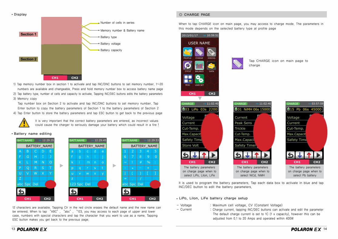
◎ CHARGE PAGE Display
LiPo, LiIon, LiFe battery charge setup
- Voltage- Current
: Maximum cell voltage, CV (Constant Voltage): Charge current, tapping INC/DEC buttons can activate and edit the parameter The default charge current is set to 1C (1 x capacity), however this can be adjusted from 0.1 to 20 Amps and operated within 400W
Battery name editing
Section 1
Section 2
Memory number & Battery name
Battery type
Battery capacity
Number of cells in series
Battery voltage
1) Tap memory number box in section 1 to activate and tap INC/DNC buttons to set memory number. 1~20
numbers are available and changeable. Press and hold memory number box to access battery name page
2) Tap battery type, number of cells and capacity to activate. Tapping INC/DEC buttons edits the battery parameters
3) Memory copy
Tap number box on Section 2 to activate and tap INC/DNC buttons to set memory number. Tap
Enter button to copy the battery parameters of Section 1 to the battery parameters of Section 2
4) Tap Enter button to store the battery parameters and tap ESC button to get back to the previous page
It is very important that the correct battery parameters are entered, as incorrect values could cause the charger to seriously damage your battery which could result in a fire !
12 characters are available. Tapping Clr in the red circle erases the default name and the new name can be entered. When to tap “ABC”, “abc”, “123, you may access to each page of upper and lower case, numbers with special characters and tap the character that you want to use as a name. Tapping ESC button makes you get back to the previous page.
When to tap CHARGE icon on main page, you may access to charge mode. The parameters in
this mode depends on the selected battery type at profile page
It is used to program the battery parameters. Tap each data box to activate in blue and tap INC/DEC button to edit the battery parameters.
Tap CHARGE icon on main page to
charge
The battery parameterson charge page when toselect LiPo, Lilon, LiFe
The battery parameterson charge page when to
select NiCd, NiMH
The battery parameterson charge page when to
select Pb battery
CH1 CH2
PROFILE AM 00:00:00
#01 BATTERY NAME
TYPE
Voltage
Capacity
LiPo
01000mAh
25.2V2S
#02 BATTERY NAME
TYPE
Voltage
Capacity
LiPo
01000mAh
25.2V2S
USER NAME
15 16
NiCd/ NiMH battery charge setup
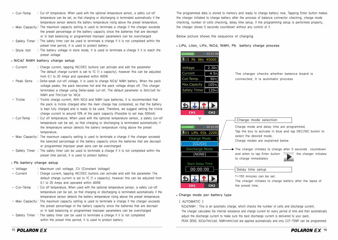
LiPo, Lilon, LiFe, NiCd, NiMH, Pb battery charge process
Charge mode per battery type
Pb battery charge setup
- Cut-Temp
- Max Capacity
- Safety Timer
- Store Volt
- Current
- Peak Sens
- Tricke
- Cut-Temp
- Max Capacity
- Safety Timer
- Voltage
- Current
- Cut-Temp
- Max Capacity
- Safety Timer
: Cut off temperature. When used with the optional temperature sensor, a safety cut-off
temperature can be set, so that charging or discharging is terminated automatically if the
temperature sensor detects the battery temperature rising above the preset temperature.
: The maximum capacity setting is used to terminate a charge if the charger exceeds
the preset percentage of the battery capacity since the batteries that are decrepit
or in bad balancing or programmed improper parameters can be overcharged
: The safety timer can be used to terminate a charge if it is not completed within the
preset time period. It is used to protect battery
: The battery voltage in store mode. It is used to terminate a charge if it is reach the
preset voltage
: Charge current, tapping INC/DEC buttons can activate and edit the parameter
The default charge current is set to 1C (1 x capacity), however this can be adjusted
from 0.1 to 20 Amps and operated within 400W
: Delta-peak cut-off voltage. It is used to charge NiCd/ NiMH battery. When the pack
voltage peaks, the pack becomes hot and the pack voltage drops off. This charger
terminates a charge using Delta-peak cut-off. The default parameter is 3mV/cell for
NiMH and 7mV/cell for NiCd
: Trickle charge current, With NiCd and NiMH type batteries, it is recommended that
the pack is trickle charged after the main charge has completed, so that the battery
is kept fully charged and is ready to be used. Therefore, we suggest setting the trickle
charge current to around 10% of the pack capacity (Possible to set max 500mA)
: Cut off temperature. When used with the optional temperature sensor, a safety cut-off
temperature can be set, so that charging or discharging is terminated automatically if
the temperature sensor detects the battery temperature rising above the preset
temperature.
: The maximum capacity setting is used to terminate a charge if the charger exceeds
the selected percentage of the battery capacity since the batteries that are decrepit
or programmed improper peak sens can be overcharged
: The safety timer can be used to terminate a charge if it is not completed within the
preset time period. It is used to protect battery
: Maximum cell voltage, CV (Constant Voltage)
: Charge current, tapping INC/DEC buttons can activate and edit the parameter The
default charge current is set to 1C (1 x capacity), however this can be adjusted from
0.1 to 20 Amps and operated within 400W
: Cut off temperature. When used with the optional temperature sensor, a safety cut-off
temperature can be set, so that charging or discharging is terminated automatically if the
temperature sensor detects the battery temperature rising above the preset temperature.
: The maximum capacity setting is used to terminate a charge if the charger exceeds
the preset percentage of the battery capacity since the batteries that are decrepit
or in bad balancing or programmed improper parameters can be overcharged
: The safety timer can be used to terminate a charge if it is not completed
within the preset time period. It is used to protect battery
The programmed data is stored to memory and ready to charge battery now. Tapping Enter button makes
the charger initiated to charge battery after the process of balance connector checking, charge mode
checking, number of cells checking, delay time setup. If the programming setup is performed properly,
the charger shows 5 seconds countdown without any control of it
Below picture shows the sequence of charging
< AUTOMATIC >
NiCd/NiMH : This is an automatic charge, which checks the number of cells and discharge current.
The charger calculates the internal resistance and charge current for every period of time and then automatically
adjust the discharge current to make sure the best discharge current is delivered to your pack.
PEAK SENS, NiCd=7mV/cell, NiMH=4mV/cell are applied automatically and only CUT-TEMP can be programmed
The charger checks whether balance board is
connected. It is automatic process
Charge mode and delay time are programmed.
Tap the box to activate in blue and tap DEC/INC button to
select the desired mode.
Charge modes are explained below
The charger initiates to charge after 5 seconds countdown
and when to tap Enter button the charger initiates
to charge immediately
1~150 minutes can be set.
The charger initiates to charge battery after the lapse of
the preset time.
Charge mode selection
Delay time setup
17 18
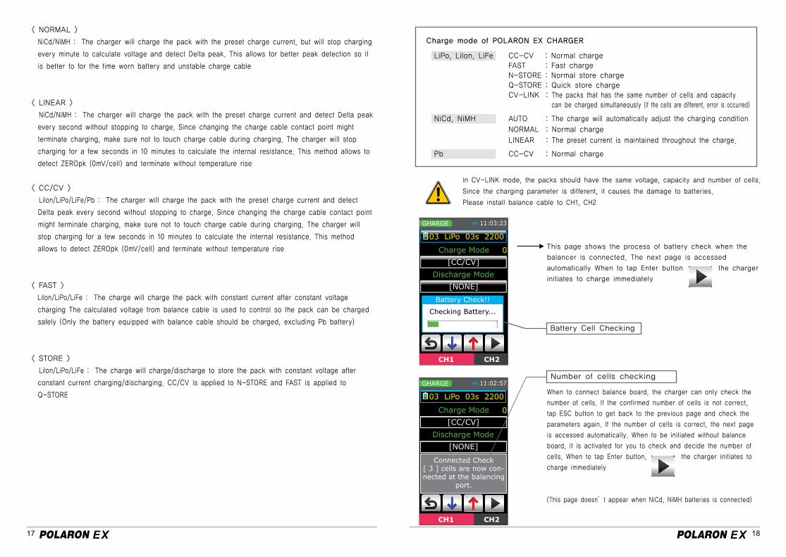
< NORMAL >
NiCd/NiMH : The charger will charge the pack with the preset charge current, but will stop charging
every minute to calculate voltage and detect Delta peak. This allows for better peak detection so it
is better to for the time worn battery and unstable charge cable
< LINEAR >
NiCd/NiMH : The charger will charge the pack with the preset charge current and detect Delta peak
every second without stopping to charge. Since changing the charge cable contact point might
terminate charging, make sure not to touch charge cable during charging. The charger will stop
charging for a few seconds in 10 minutes to calculate the internal resistance. This method allows to
detect ZEROpk (0mV/cell) and terminate without temperature rise
< CC/CV >
LiIon/LiPo/LiFe/Pb : The charger will charge the pack with the preset charge current and detect
Delta peak every second without stopping to charge. Since changing the charge cable contact point
might terminate charging, make sure not to touch charge cable during charging. The charger will
stop charging for a few seconds in 10 minutes to calculate the internal resistance. This method
allows to detect ZEROpk (0mV/cell) and terminate without temperature rise
< FAST >
LiIon/LiPo/LiFe : The charge will charge the pack with constant current after constant voltage
charging The calculated voltage from balance cable is used to control so the pack can be charged
safely (Only the battery equipped with balance cable should be charged, excluding Pb battery)
< STORE >
LiIon/LiPo/LiFe : The charge will charge/discharge to store the pack with constant voltage after
constant current charging/discharging. CC/CV is applied to N-STORE and FAST is applied to
Q-STORE
Charge mode of POLARON EX CHARGER
CC-CV : Normal charge FAST : Fast chargeN-STORE : Normal store chargeQ-STORE : Quick store chargeCV-LINK : The packs that has the same number of cells and capacity can be charged simultaneously (If the cells are different, error is occurred)
AUTO : The charge will automatically adjust the charging condition
NORMAL : Normal charge
LINEAR : The preset current is maintained throughout the charge.
CC-CV : Normal charge
In CV-LINK mode, the packs should have the same voltage, capacity and number of cells.
Since the charging parameter is different, it causes the damage to batteries.
Please install balance cable to CH1, CH2
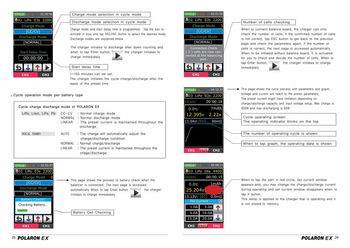
This page shows the process of battery check when the
balancer is connected. The next page is accessed
automatically When to tap Enter button the charger
initiates to charge immediately
When to connect balance board, the charger can only check the
number of cells. If the confirmed number of cells is not correct,
tap ESC button to get back to the previous page and check the
parameters again. If the number of cells is correct, the next page
is accessed automatically. When to be initiated without balance
board, it is activated for you to check and decide the number of
cells. When to tap Enter button, the charger initiates to
charge immediately
(This page doesn’t appear when NiCd, NiMH batteries is connected)
Number of cells checking
LiPo, LiIon, LiFe
NiCd, NiMH
Pb
Battery Cell Checking
19 20
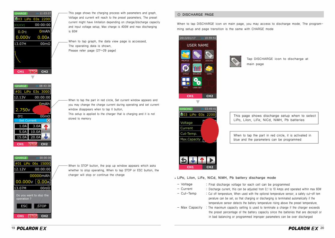
This page shows the charging process with parameters and graph.
Voltage and current will reach to the preset parameters. The preset
current might have limitation depending on charge/discharge capacity
and input voltage setup. Max charge is 400W and max discharging
is 60W
When to tap graph, the data view page is accessed.
The operating data is shown.
Please refer page (27~29 page)
When to tap the part in red circle, Set current window appears and
you may change the charge current during operating and set current
window disappears when to tap X button.
This setup is applied to the charger that is charging and it is not
stored to memory
When to STOP button, the pop up window appears which asks
whether to stop operating. When to tap STOP or ESC button, the
charger will stop or continue the charge
◎ DISCHARGE PAGE
When to tap DISCHARGE icon on main page, you may access to discharge mode. The program-
ming setup and page transition is the same with CHARGE mode
Tap DISCHARGE icon to discharge at
main page
This page shows discharge setup when to selectLiPo, Lilon, LiFe, NiCd, NiMH, Pb batteries
When to tap the part in red circle, it is activated in blue and the parameters can be programmed
LiPo, LiIon, LiFe, NiCd, NiMH, Pb battery discharge mode
- Voltage
- Current
- Cut-Temp
- Max Capacity
: Final discharge voltage for each cell can be programmed
: Discharge current, this can be adjusted from 0.1 to 10 Amps and operated within max 60W
: Cut off temperature. When used with the optional temperature sensor, a safety cut-off tem
perature can be set, so that charging or discharging is terminated automatically if the
temperature sensor detects the battery temperature rising above the preset temperature.
: The maximum capacity setting is used to terminate a charge if the charger exceeds
the preset percentage of the battery capacity since the batteries that are decrepit or
in bad balancing or programmed improper parameters can be over discharged
USER NAME
The programmed data is stored to memory and ready to charge battery now. Tapping Enter
button makes the charger initiated to charge battery after the process of balance connector
checking, charge mode checking, number of cells checking, delay time setup.
If the programming setup is performed properly, the charger shows 5 seconds countdown
without any control of it. Below picture shows the sequence of charging
21 22
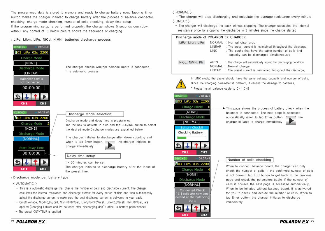
LiPo, Lilon, LiFe, NiCd, NiMH batteries discharge process
The charger checks whether balance board is connected.
It is automatic process
Discharge mode and delay time is programmed.
Tap the box to activate in blue and tap DEC/INC button to select
the desired mode.Discharge modes are explained below
Discharge mode selection
The charger initiates to discharge after down counting and
when to tap Enter button, the charger initiates to
charge immediately
1~150 minutes can be set.
The charger initiates to discharge battery after the lapse of
the preset time.
Delay time setup
Discharge mode per battery type
< AUTOMATIC >
- This is a automatic discharge that checks the number of cells and discharge current. The charger
calculates the internal resistance and discharge current for every period of time and then automatically
adjust the discharge current to make sure the best discharge current is delivered to your pack.
- Cutoff voltage, NiCd=0.9V/cell, NiMH=0.8V/cell, LiIon/Po=3.0V/cell, LiFe=2.5V/cell, Pb=1.8V/cell, are
applied (Charging Lithium and Pb batteries after discharging don’t affect to battery performance)
- The preset CUT-TEMP is applied
< NORMAL >
- The charge will stop discharging and calculate the average resistance every minute
< LINEAR >
- The charger will discharge the pack without stopping. The charger calculates the internal
resistance once by stopping the discharge in 3 minutes since the charge started
Discharge mode of POLARON EX CHARGER
LiPo, LiIon, LiFe
NiCd, NiMH, Pb
NORMAL : Normal discharge LINEAR : The preset current is maintained throughout the discharge.LINK : The packs that have the same number of cells and capacity can be discharged simultaneously
AUTO : The charge will automatically adjust the discharging condition
NORMAL : Normal charge
LINEAR : The preset current is maintained throughout the discharge.
In LINK mode, the packs should have the same voltage, capacity and number of cells.
Since the charging parameter is different, it causes the damage to batteries.
* Please install balance cable to CH1, CH2
This page shows the process of battery check when the
balancer is connected. The next page is accessed
automatically When to tap Enter button the
charger initiates to charge immediately
When to connect balance board, the charger can only
check the number of cells. If the confirmed number of cells
is not correct, tap ESC button to get back to the previous
page and check the parameters again. If the number of
cells is correct, the next page is accessed automatically.
When to be initiated without balance board, it is activated
for you to check and decide the number of cells. When to
tap Enter button, the charger initiates to discharge
immediately
Number of cells checking
23 24
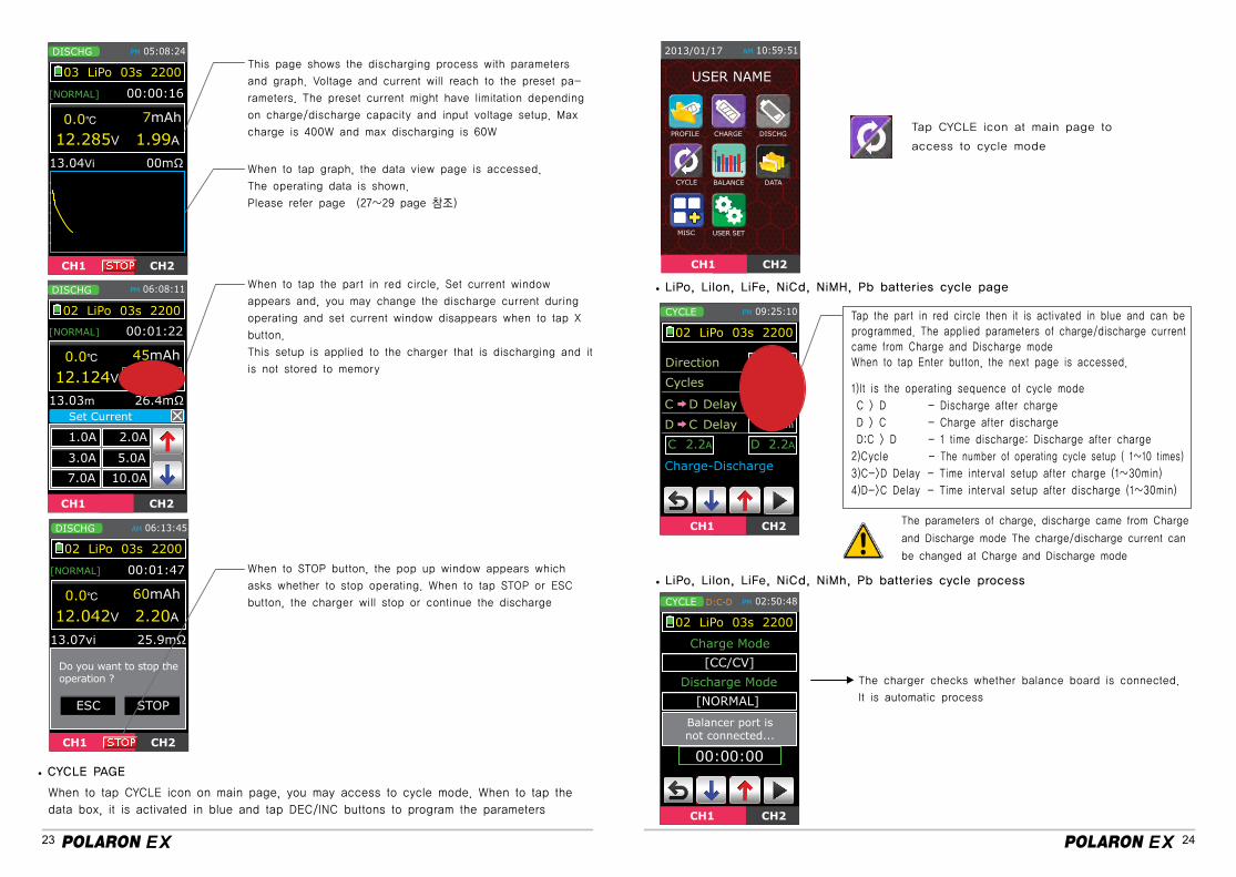
This page shows the discharging process with parameters
and graph. Voltage and current will reach to the preset pa-
rameters. The preset current might have limitation depending
on charge/discharge capacity and input voltage setup. Max
charge is 400W and max discharging is 60W
When to tap graph, the data view page is accessed.
The operating data is shown.
Please refer page (27~29 page 참조)
When to tap the part in red circle, Set current window
appears and, you may change the discharge current during
operating and set current window disappears when to tap X
button.
This setup is applied to the charger that is discharging and it
is not stored to memory
When to STOP button, the pop up window appears which
asks whether to stop operating. When to tap STOP or ESC
button, the charger will stop or continue the discharge
When to tap CYCLE icon on main page, you may access to cycle mode. When to tap the
data box, it is activated in blue and tap DEC/INC buttons to program the parameters
CYCLE PAGE
LiPo, Lilon, LiFe, NiCd, NiMH, Pb batteries cycle page
Tap CYCLE icon at main page to
access to cycle mode
Tap the part in red circle then it is activated in blue and can be programmed. The applied parameters of charge/discharge current came from Charge and Discharge modeWhen to tap Enter button, the next page is accessed.
1)It is the operating sequence of cycle mode
C > D - Discharge after charge
D > C - Charge after discharge
D:C > D - 1 time discharge: Discharge after charge
2)Cycle - The number of operating cycle setup ( 1~10 times)
3)C->D Delay - Time interval setup after charge (1~30min)
4)D->C Delay - Time interval setup after discharge (1~30min)
The parameters of charge, discharge came from Charge
and Discharge mode The charge/discharge current can
be changed at Charge and Discharge mode
LiPo, Lilon, LiFe, NiCd, NiMh, Pb batteries cycle process
The charger checks whether balance board is connected.
It is automatic process
USER NAME
25 26
Discharge mode selection in cycle mode
Charge mode selection in cycle mode
1~150 minutes can be set.
The charger initiates the cycle charge/discharge after the
lapse of the preset time.
Start delay time
The number of operating cycle is shown
Cycle operating screenThe operating indicator blinks on the top
When to tap graph, the operating data is shown
Charge mode and start delay time is programmed. Tap the box to
activate in blue and tap DEC/INC button to select the desired mode.
Discharge modes are explained below
The charger initiates to discharge after down counting and
when to tap Enter button, the charger initiates to
charge immediately
When to connect balance board, the charger can only
check the number of cells. If the confirmed number of cells
is not correct, tap ESC button to get back to the previous
page and check the parameters again. If the number of
cells is correct, the next page is accessed automatically.
When to be initiated without balance board, it is activated
for you to check and decide the number of cells. When to
tap Enter button, the charger initiates to charge
immediately
This page shows the process of battery check when the
balancer is connected. The next page is accessed
automatically When to tap Enter button the charger
initiates to charge immediately
When to tap the part in red circle, Set current window
appears and, you may change the charge/discharge current
during operating and set current window disappears when to
tap X button.
This setup is applied to the charger that is operating and it
is not stored to memory
This page shows the cycle process with parameters and graph.
Voltage and current will reach to the preset parameters.
The preset current might have limitation depending on
charge/discharge capacity and input voltage setup. Max charge is
400W and max discharging is 60W
Cycle operation mode per battery type
Cycle charge discharge mode of POLARON EX
LiPo, LiIon, LiFe, Pb
NiCd, NiMH
CC-CV : Normal charge modeNORMAL : Normal discharge modeLINEAR : The preset current is maintained throughout the discharge.
AUTO : The charge will automatically adjust the
charge/discharge condition
NORMAL : Normal charge/discharge
LINEAR : The preset current is maintained throughout the
chage/discharge.
Battery Cell Checking
Number of cells checking
27 28
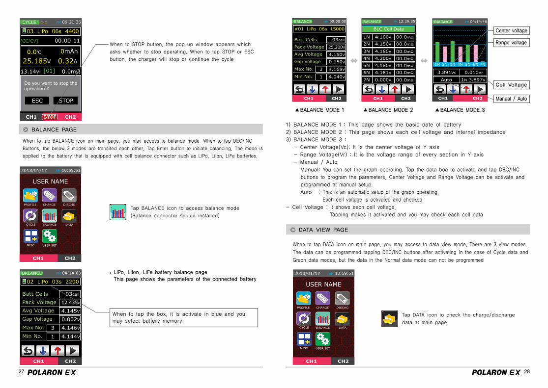
When to STOP button, the pop up window appears which
asks whether to stop operating. When to tap STOP or ESC
button, the charger will stop or continue the cycle
◎ BALANCE PAGE
◎ DATA VIEW PAGE
When to tap BALANCE icon on main page, you may access to balance mode. When to tap DEC/INC
Buttons, the below 3 modes are transited each other. Tap Enter button to initiate balancing. The mode is
applied to the battery that is equipped with cell balance connector such as LiPo, LiIon, LiFe batteries.
Tap BALANCE icon to access balance mode
(Balance connector should installed)
Tap DATA icon to check the charge/discharge
data at main page
LiPo, Lilon, LiFe battery balance pageThis page shows the parameters of the connected battery
When to tap the box, it is activate in blue and you may select battery memory
BALANCE MODE 1 BALANCE MODE 2 ▲ ▲ ▲
When to tap DATA icon on main page, you may access to data view mode. There are 3 view modes
The data can be programmed tapping DEC/INC buttons after activating in the case of Cycle data and
Graph data modes, but the data in the Normal data mode can not be programmed
BALANCE MODE 3
1) BALANCE MODE 1 : This page shows the basic date of battery
2) BALANCE MODE 2 : This page shows each cell voltage and internal impedance
3) BALANCE MODE 3 :
- Center Voltage(Vc): It is the center voltage of Y axis
- Range Voltage(Vr) : It is the voltage range of every section in Y axis
- Manual / Auto
Manual: You can set the graph operating. Tap the data boa to activate and tap DEC/INC
buttons to program the parameters. Center Voltage and Range Voltage can be activate and
programmed at manual setup
Auto : This is an automatic setup of the graph operating.
Each cell voltage is activated and checked
- Cell Voltage : it shows each cell voltage.
Tapping makes it activated and you may check each cell data
Center voltage
Range voltage
Cell Voltage
Manual / Auto
USER NAME
USER NAME
29 30
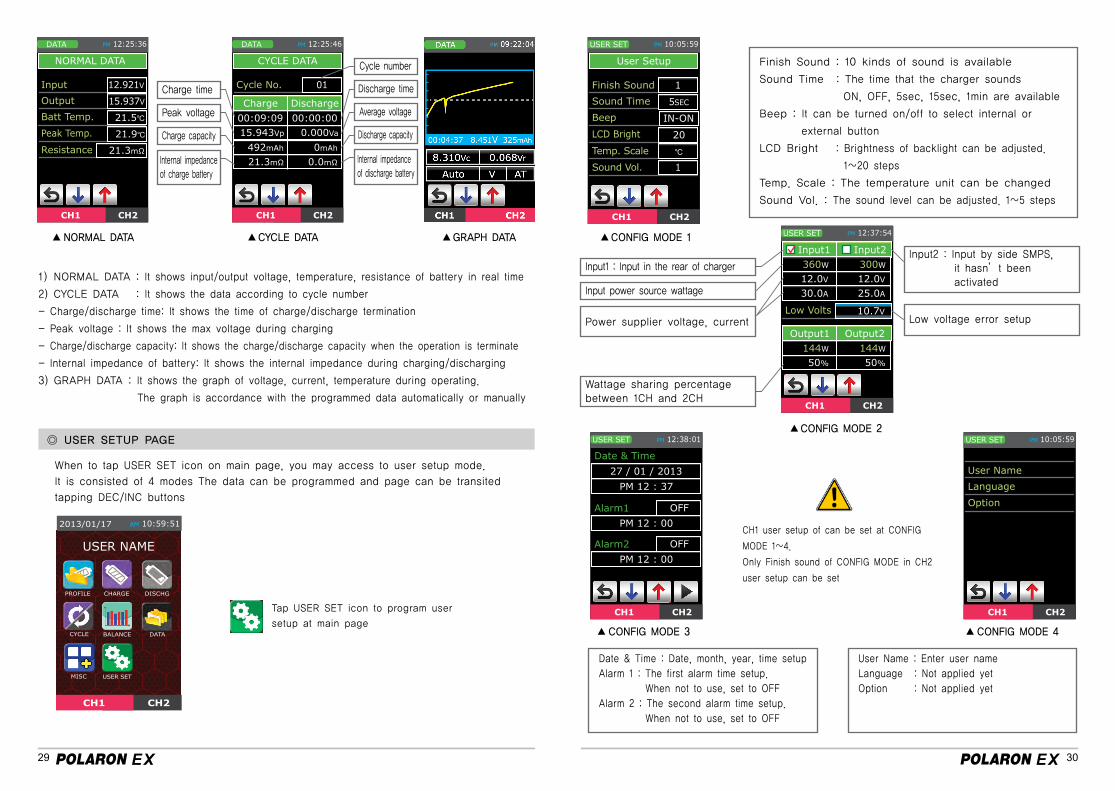
NORMAL DATA CYCLE DATA GRAPH DATA CONFIG MODE 1
CONFIG MODE 2
CONFIG MODE 3 CONFIG MODE 4
▲▲ ▲ ▲
▲
▲ ▲
1) NORMAL DATA : It shows input/output voltage, temperature, resistance of battery in real time
2) CYCLE DATA : It shows the data according to cycle number
- Charge/discharge time: It shows the time of charge/discharge termination
- Peak voltage : It shows the max voltage during charging
- Charge/discharge capacity: It shows the charge/discharge capacity when the operation is terminate
- Internal impedance of battery: It shows the internal impedance during charging/discharging
3) GRAPH DATA : It shows the graph of voltage, current, temperature during operating.
The graph is accordance with the programmed data automatically or manually
◎ USER SETUP PAGE
Tap USER SET icon to program user
setup at main page
When to tap USER SET icon on main page, you may access to user setup mode.
It is consisted of 4 modes The data can be programmed and page can be transited
tapping DEC/INC buttons
Finish Sound : 10 kinds of sound is available
Sound Time : The time that the charger sounds
ON, OFF, 5sec, 15sec, 1min are available
Beep : It can be turned on/off to select internal or
external button
LCD Bright : Brightness of backlight can be adjusted.
1~20 steps
Temp. Scale : The temperature unit can be changed
Sound Vol. : The sound level can be adjusted. 1~5 steps
Date & Time : Date, month, year, time setup
Alarm 1 : The first alarm time setup.
When not to use, set to OFF
Alarm 2 : The second alarm time setup.
When not to use, set to OFF
User Name : Enter user name
Language : Not applied yet
Option : Not applied yet
Input1 : Input in the rear of charger
Input power source wattage
Power supplier voltage, current
Wattage sharing percentage between 1CH and 2CH
Low voltage error setup
Input2 : Input by side SMPS, it hasn’t been activated
CH1 user setup of can be set at CONFIG
MODE 1~4.
Only Finish sound of CONFIG MODE in CH2
user setup can be set
Charge time Discharge time
Cycle number
Peak voltage Average voltage
Charge capacity Discharge capacity
Internal impedance of charge battery
Internal impedanceof discharge battery
USER NAME
31 32
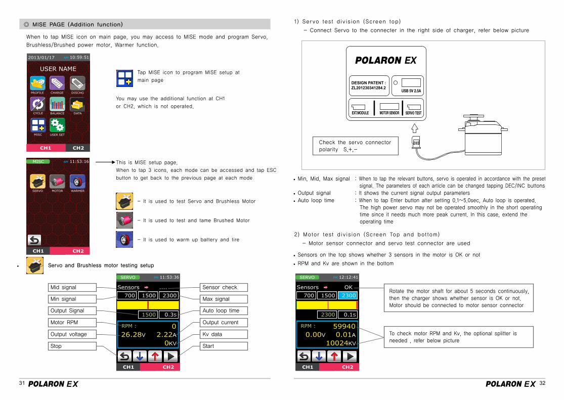
◎ MISE PAGE (Addition function)
Tap MISE icon to program MISE setup at
main page
You may use the additional function at CH1
or CH2, which is not operated.
This is MISE setup page.
When to tap 3 icons, each mode can be accessed and tap ESC
button to get back to the previous page at each mode
When to tap MISE icon on main page, you may access to MISE mode and program Servo,
Brushless/Brushed power motor, Warmer function.
- It is used to test Servo and Brushless Motor
- It is used to test and tame Brushed Motor
- It is used to warm up battery and tire
Servo and Brushless motor testing setup
Check the servo connector polarity S,+,-
1) Servo test division (Screen top)
- Connect Servo to the connecter in the right side of charger, refer below picture
2) Motor test division (Screen Top and bottom)
- Motor sensor connector and servo test connector are used
Min, Mid, Max signal
Auto loop time Output signal
Sensors on the top shows whether 3 sensors in the motor is OK or not
RPM and Kv are shown in the bottom
: When to tap the relevant buttons, servo is operated in accordance with the preset signal. The parameters of each article can be changed tapping DEC/INC buttons
: When to tap Enter button after setting 0.1~5.0sec, Auto loop is operated. The high power servo may not be operated smoothly in the short operating time since it needs much more peak current. In this case, extend the operating time
Rotate the motor shaft for about 5 seconds continuously, then the charger shows whether sensor is OK or not.Motor should be connected to motor sensor connector
To check motor RPM and Kv, the optional splitter is needed , refer below picture
: It shows the current signal output parameters
Mid signal Sensor check
Min signal Max signal
Output Signal Auto loop time
Motor RPM Output current
Output voltage Kv data
Stop Start
USER NAME
33 34
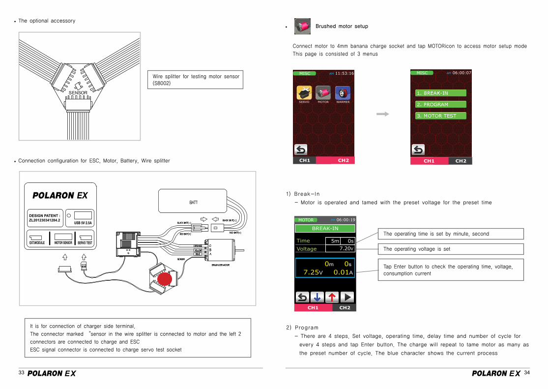
The optional accessory
Connection configuration for ESC, Motor, Battery, Wire splitter
Wire splitter for testing motor sensor (S8002)
It is for connection of charger side terminal.
The connector marked “sensor in the wire splitter is connected to motor and the left 2
connectors are connected to charge and ESC
ESC signal connector is connected to charge servo test socket
Brushed motor setup
Connect motor to 4mm banana charge socket and tap MOTORicon to access motor setup mode
This page is consisted of 3 menus
1) Break-In
- Motor is operated and tamed with the preset voltage for the preset time
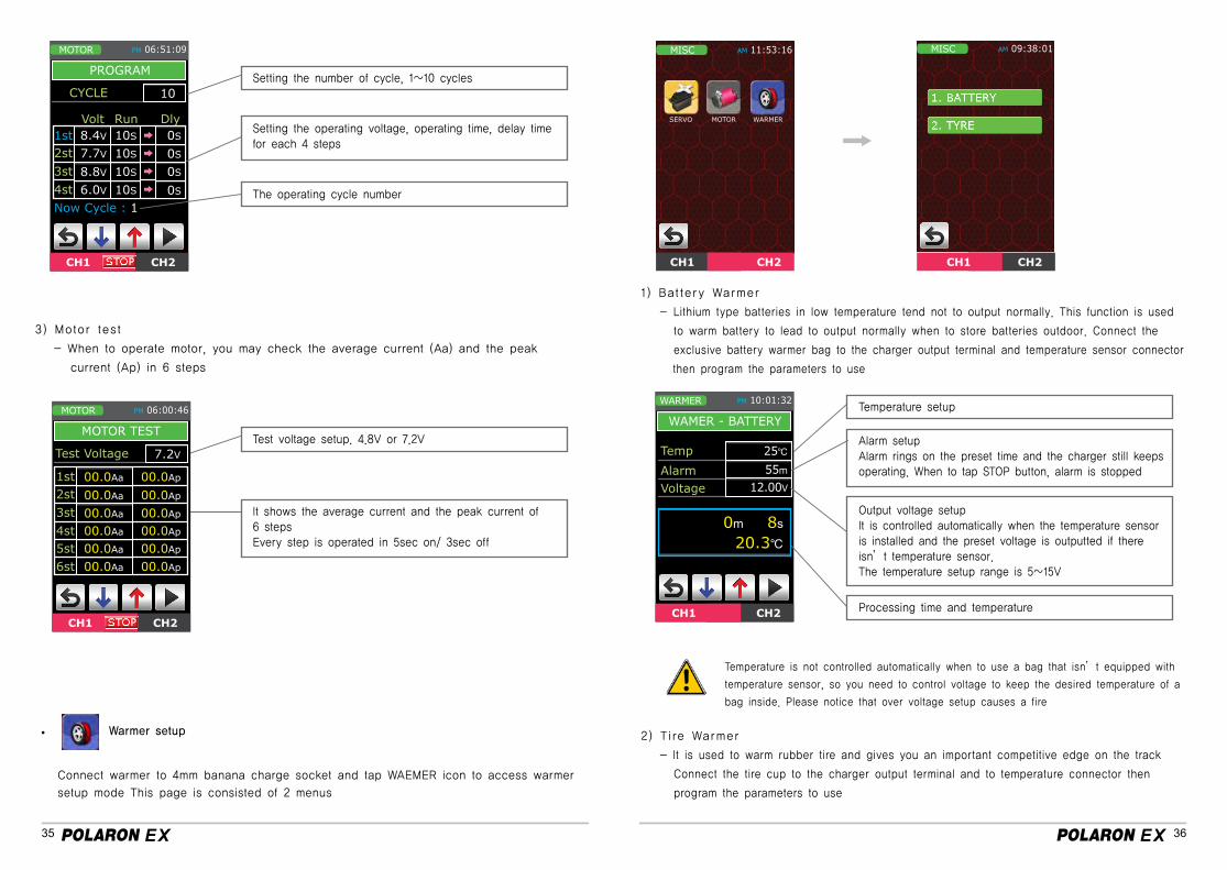
2) Program
- There are 4 steps. Set voltage, operating time, delay time and number of cycle for
every 4 steps and tap Enter button. The charge will repeat to tame motor as many as
the preset number of cycle. The blue character shows the current process
The operating time is set by minute, second
The operating voltage is set
Tap Enter button to check the operating time, voltage, consumption current
35 36
3) Motor test
- When to operate motor, you may check the average current (Aa) and the peak
current (Ap) in 6 steps
Test voltage setup. 4.8V or 7.2V
It shows the average current and the peak current of6 stepsEvery step is operated in 5sec on/ 3sec off
Setting the number of cycle, 1~10 cycles
Setting the operating voltage, operating time, delay time for each 4 steps
The operating cycle number
Warmer setup
Connect warmer to 4mm banana charge socket and tap WAEMER icon to access warmer
setup mode This page is consisted of 2 menus
1) Battery Warmer
- Lithium type batteries in low temperature tend not to output normally. This function is used
to warm battery to lead to output normally when to store batteries outdoor. Connect the
exclusive battery warmer bag to the charger output terminal and temperature sensor connector
then program the parameters to use
2) Tire Warmer
- It is used to warm rubber tire and gives you an important competitive edge on the track
Connect the tire cup to the charger output terminal and to temperature connector then
program the parameters to use
Temperature setup
Alarm setup Alarm rings on the preset time and the charger still keeps operating. When to tap STOP button, alarm is stopped
Output voltage setupIt is controlled automatically when the temperature sensor is installed and the preset voltage is outputted if there isn’t temperature sensor.The temperature setup range is 5~15V
Processing time and temperature
Temperature is not controlled automatically when to use a bag that isn’t equipped with
temperature sensor, so you need to control voltage to keep the desired temperature of a
bag inside. Please notice that over voltage setup causes a fire
37 38
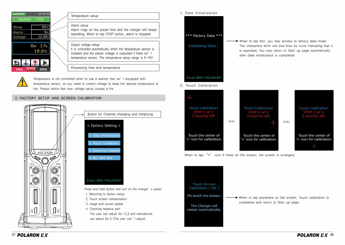
Temperature setup
Alarm setup Alarm rings on the preset time and the charger still keeps operating. When to tap STOP button, alarm is stopped
Output voltage setupIt is controlled automatically when the temperature sensor is installed and the preset voltage is outputted if there isn’t temperature sensor. The temperature setup range is 5~15V
Processing time and temperature
Button for Channel changing and initializing
Temperature is not controlled when to use a warmer that isn’t equipped with
temperature sensor, so you need to control voltage to keep the desired temperature of
tire. Please notice that over voltage setup causes a fire
Press and hold button and turn on the charger’s power
1. Returning to factory setup
2. Touch screen compensation
3. Image and sound update
4. Checking balance port
The user can adjust No 1,2,3 and manufacture
can adjust No 4 (The user can’t adjust)
1. Data Initialization
2. Touch Calibration
When to tap No1, you may access to factory data mode.
The characters blink red and blue by turns indicating that it
is operated. You may return to Start up page automatically
after Data Initialization is completed
When to tap “+” icon 3 times on the screen, the screen is arranged.
When to tap anywhere on the screen, Touch calibration is
completed and return to Start up page
◎ FACTORY SETUP AND SCREEN CALIBRATION
< Factory Setting >
Smart BMS *POLARON*
1. Data Initialization
2. Touch Calibration
3. Resource Upgrade
4. BLC Port Test
*** Factory Data ***
Initializing Data...
Smart BMS *POLARON*
39 40
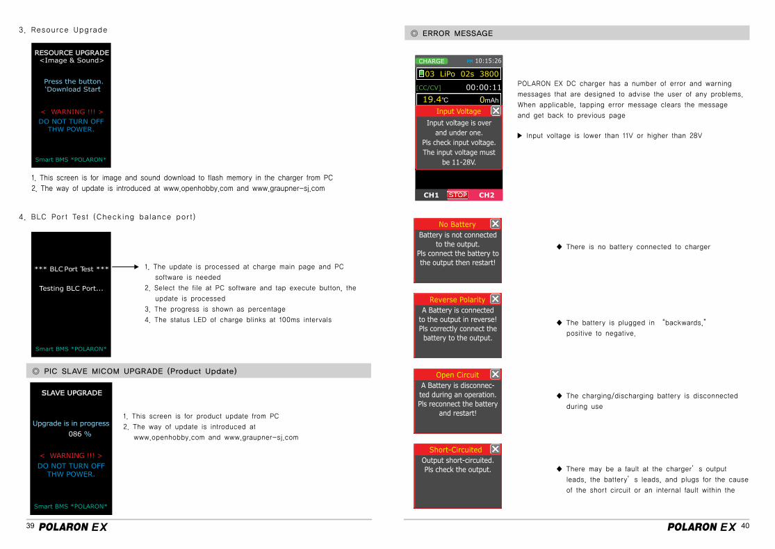
3. Resource Upgrade
4. BLC Port Test (Checking balance port)
1. This screen is for image and sound download to flash memory in the charger from PC
2. The way of update is introduced at www.openhobby.com and www.graupner-sj.com
1. This screen is for product update from PC
2. The way of update is introduced at
www.openhobby.com and www.graupner-sj.com
1. The update is processed at charge main page and PC
software is needed
2. Select the file at PC software and tap execute button, the
update is processed
3. The progress is shown as percentage
4. The status LED of charge blinks at 100ms intervals
◎ ERROR MESSAGE
POLARON EX DC charger has a number of error and warning
messages that are designed to advise the user of any problems.
When applicable, tapping error message clears the message
and get back to previous page
▶ Input voltage is lower than 11V or higher than 28V
◆ There is no battery connected to charger
◆ The battery is plugged in “backwards,”
positive to negative.
◆ The charging/discharging battery is disconnected
during use
◆ There may be a fault at the charger’s output
leads, the battery’s leads, and plugs for the cause
of the short circuit or an internal fault within the
No Battery
Reverse Polarity
Open Circuit
Short-Circuited
Battery is not connectedto the output.
Pls connect the battery tothe output then restart!
A Battery is connectedto the output in reverse!Pls correctly connect thebattery to the output.
A Battery is disconnec-ted during an operation.Pls reconnect the battery
and restart!
Output short-circuited.Pls check the output.
◎ PIC SLAVE MICOM UPGRADE (Product Update)
DO NOT TURN OFFTHW POWER.
<Image & Sound>RESOURCE UPGRADE
Press the button.‘Download Start’
< WARNING !!! >
Smart BMS *POLARON*
*** BLC Port Test ***
Testing BLC Port...
Smart BMS *POLARON*
41 42
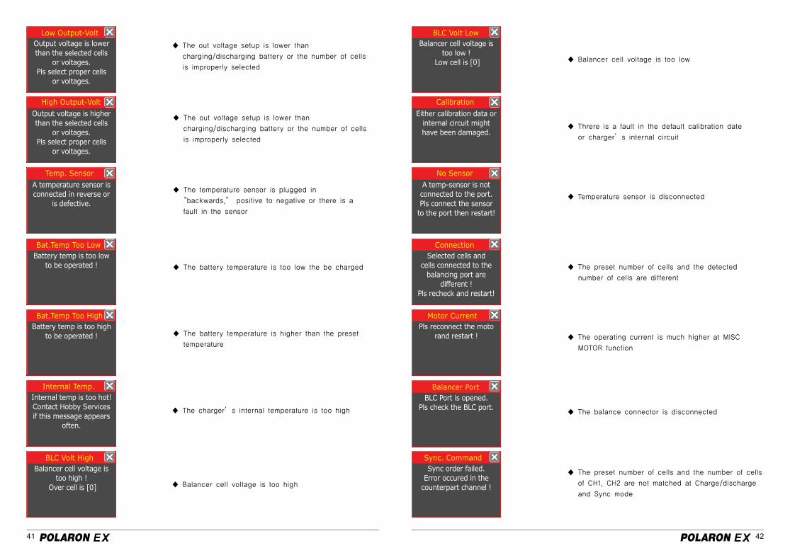
◆ The out voltage setup is lower than
charging/discharging battery or the number of cells
is improperly selected
◆ The temperature sensor is plugged in
“backwards,” positive to negative or there is a
fault in the sensor
◆ The battery temperature is too low the be charged
◆ The battery temperature is higher than the preset
temperature
◆ The charger’s internal temperature is too high
◆ Balancer cell voltage is too high
◆ Balancer cell voltage is too low
◆ Threre is a fault in the default calibration date
or charger’s internal circuit
◆ Temperature sensor is disconnected
◆ The preset number of cells and the detected
number of cells are different
◆ The operating current is much higher at MISC
MOTOR function
◆ The balance connector is disconnected
◆ The out voltage setup is lower than
charging/discharging battery or the number of cells
is improperly selected
◆ The preset number of cells and the number of cells
of CH1, CH2 are not matched at Charge/discharge
and Sync mode
Low Output-Volt BLC Volt Low
High Output-Volt Calibration
Internal Temp.
Motor Current
Temp. Sensor No Sensor
BLC Volt High
Balancer Port
Bat.Temp Too High
Bat.Temp Too Low Connection
Sync. Command
Output voltage is lowerthan the selected cells
or voltages.Pls select proper cells
or voltages.
Balancer cell voltage is too low !
Low cell is [0]
Output voltage is higherthan the selected cells
or voltages.Pls select proper cells
or voltages.
Either calibration data or internal circuit might have been damaged.
Internal temp is too hot!Contact Hobby Services if this message appears
often.
Pls reconnect the motorand restart !
A temperature sensor isconnected in reverse or
is defective.
A temp-sensor is notconnected to the port.Pls connect the sensor
to the port then restart!
Balancer cell voltage is too high !
Over cell is [0]
BLC Port is opened.Pls check the BLC port.
Battery temp is too high to be operated !
Battery temp is too lowto be operated !
Selected cells andcells connected to the
balancing port aredifferent !
Pls recheck and restart!
Sync order failed.Error occured in the
counterpart channel !
43 44
◎ USE OF PROBLEM AND PRECAUTION FOR POLARON EX DC CHARGER
- Turning on the charge, but LCD Screen is off
. Check if the correct external power source, this charge should be operated only from
the type of power source indicated on the specification. In case that the problem is
not settled, please contact A/S center
- The charger doesn’t recognize battery . Check if the battery connection and polarity are correct. Change the cable if the worn
out cable is used . Change the damaged cell in battery pack if a cell is damaged
- Battery voltage is low after charging (Each cell voltage of NiCd, NiMH is lower than
1.2V or each cell voltage of LiPo, LiIon is lower than 3.6V or 3.7V) . Increase the max charge capacity if it is too low. . Control Peak sens of NiCd, NiMH if it is too low or high and change the charge cable
if the worn out cable is used
- Discharging mode is not accessed . Match the preset battery voltage and the cell voltage . Change the damaged cell in battery pack if a cell is damaged
- mAh/time is too low after charging
. Battery might not be fully charged, fully charge battery and discharge again. Perform
cycle to improve battery capacity if battery is worn out or not used for a long time. . Reduce discharge cut off voltage if it is programmed too high and control the
discharge ratio.
. Match the preset battery voltage and the cell voltage.
. When to discharge with over current, make sure to discharge the remained current
again. For example, when to discharge with higher than 5A, cool down the battery and
then discharge with 1A again
- Charge Lithium type battery
. Make sure to use a balance board and must use EH to XH cable
. Do not charge Lithium battery packs above their maximum charge rate. This can
damage the pack and can be dangerous. Generally, Lithium Polymer packs should not
be charged above 3C. However, some newer packs do allow charging at up to 5C, but
charging at these higher rates will reduce the life of the pack.
◎ NEW BATTERY CHARGE
◎ Pb BATTERY SAFETY
◎ LiIon, LiPo, LiFe BATTREIES SAFETY
- When the new NiCd/ NiMH are charged at the first time, charge process might be
terminated within minutes, it is not because charger or battery have a problem, but
because battery is not stabilized yet. In this case, you need to charge battery after
increasing the delta peak value or to charge battery after discharging and cooling down
battery.
Do not use the battery, if the charged capacity of battery exceeds battery capacity in
specification. If such a phenomenon arises, repeat to charge and discharge more over 5
times and charge again.
- Pb battery needs to be charged every day. If the charged capacity of battery is
dropped below 50%, this battery might not be recharged. The average charge time of
Pb battery is 4~5 hours. Do not charge an automobile battery, the charger might get the
serious damage
- Always charge the batteries that have Lithium ion or Lithium polymer mark and do not charge
the batteries that have Lithium mark. Failure to do so will damage the batteries and may cause
fire or personal injury.
- Always charge the batteries that the cell voltage ( 3.3V / 3.6V / 3.7V ) is written
- Ensure that the charger and battery are placed on a non-flammable surface whilst charging.
- Never charge Lithium ion/Polymer/Fe batteries inside a vehicle whatever the circumstances.
- Always ensure that the charger is correctly set for the battery being charged, checking both
voltage and capacity. Be particularly careful if using a series/parallel battery pack, or if using
packs of different specifications with the same charger.
- Never charge at a rate higher than that recommended by the cell manufacturer, this can be
very dangerous.
- Do not leave Lithium ion/Polymer/Fe batteries unattended whilst they are charging. Monitoring
the batteries during charging is very important.
- Always monitor the temperature of the battery being charged every few minutes. If the battery
becomes hot to the touch, disconnect it from the charger immediately and allow to cool. Do not
recommence charging until the battery and charger have been checked for compatibility and the
charger settings have been confirmed as being correct.
- In the unlikely event of the Lithium ion/Polymer/Fe battery catching fire DO NOT use water to
attempt to put the fire out, instead use sand or a fire extinguisher designed for electrical fires.
45 46
- When used correctly, Lithium ion/Polymer/Fe battery packs are as safe as any other type of rechargea
ble battery pack. However they do require different charge regimes to the longer established Nickel
Cadmium and Nickel Metal Hydride technologies and have the potential of catching fire if severely
mistreated.
- If Lithium Polymer battery packs are short-circuited or severely over-charged elemental Lithium may be
deposited internally, and if the battery pouch is damaged this can escape from inside the battery. If this
occurs a fire may be caused, as elemental Lithium is highly reactive when exposed to water or moisture,
producing flammable hydrogen gas and corrosive fumes. Elemental Lithium is not produced unless the
battery pack is severely mistreated, so in normal usage there is no likelihood of explosion or fire.
- Lithium Ion/Polymer battery packs must NEVER be discharged below 3 volts per cell (Li-Fe 2.0V) as
this will result in damage to the cells. If the voltage is allowed to drop below 3 volts per cell the
battery voltage may seem to recover following a charge, but the battery may not then give its full
nominal capacity and a reduction in performance is likely-allowing the voltage to drop below 3 volts per
cell will invalidate all warranty claims.
- Never charge Lithium Polymer battery packs at greater than 4.2V per cell, Lithium Ion at 4.1V volts per
cell or LiFe at greater than 3.7V per cell as this will cause irreversible damage to the cells and will
invalidate all warranty claims.
- Never charge Lithium battery packs above their maximum charge rate. This can damage the pack and
can be dangerous. Generally, Lithium Polymer packs should not be charged above 2C (2 x Capacity).
However, some newer packs do allow charging at up to 5C, but charging at these higher rates will
reduce the life of the pack.
e.g Pack of 2500mAh capacity : 2C = 5000mAh = 5A max
- Do not use discharge rates in excess of those specified with the battery pack as this will result
in a significant drop in voltage under load and will dramatically reduce the number of
charge/discharge cycles the battery pack will give. If disposing of Lithium battery packs ensure
that the pack is fully discharged by using a light bulb, electric motor or similar to completely
discharge the pack.
Do not allow any Lithium battery pack to short-circuit as this is likely to result in a
minor explosion and consequent fire.
www.graupner-sj.comwww.openhobby.com
◎ COMPLIANCE INFORAMTION FOR THE EUROPEAN UNION
- Before charging any Lithium battery packs they should be closely inspected for any damage,
such as punctures in the sleeving or if the battery has swollen or expanded in size. If any
such damage is detected Do not charge, even if the battery otherwise appears to be brand
new.
- Before commencing charging always double check the settings on the charger to ensure it is
set correctly for the battery pack to be charged. Using the wrong settings is likely to result in
damage to the battery pack being charged and could result in the battery catching fire.
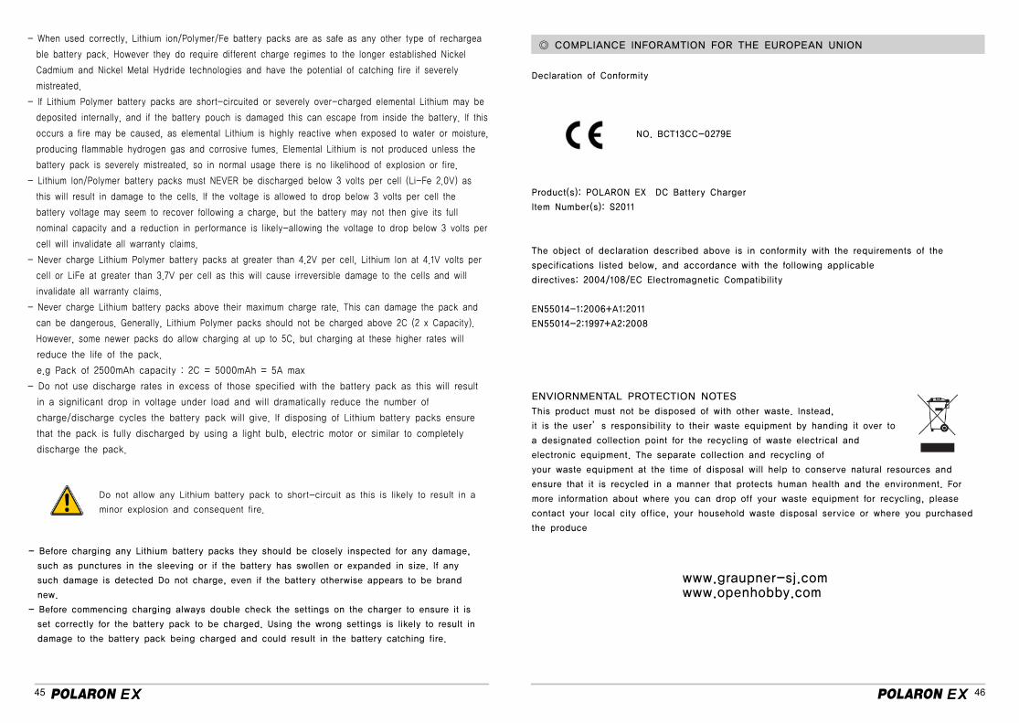
Declaration of Conformity
NO. BCT13CC-0279E
Product(s): POLARON EX DC Battery Charger
Item Number(s): S2011
The object of declaration described above is in conformity with the requirements of the
specifications listed below, and accordance with the following applicable
directives: 2004/108/EC Electromagnetic Compatibility
EN55014-1:2006+A1:2011
EN55014-2:1997+A2:2008
ENVIORNMENTAL PROTECTION NOTES
This product must not be disposed of with other waste. Instead,
it is the user’s responsibility to their waste equipment by handing it over to
a designated collection point for the recycling of waste electrical and
electronic equipment. The separate collection and recycling of
your waste equipment at the time of disposal will help to conserve natural resources and
ensure that it is recycled in a manner that protects human health and the environment. For
more information about where you can drop off your waste equipment for recycling, please
contact your local city office, your household waste disposal service or where you purchased
the produce