newport medical instruments, inc. newport ht70 series...
TRANSCRIPT
Newport Medical Instruments, Inc.
Newport HT70 Series Ventilator
Service ManualSERHT70-2 Rev. B
05/14
Newport Medical Instruments, Inc.1620 Sunflower Ave.Costa Mesa, CA 92626
Email: [email protected]

Page Left Intentionally Blank

OPR360U A05095-1
5
OPR360U A0509 5-1
5
SERHT70-2 B0514
Contact InformationContact Information
Telephone: 800-255-6774 option #4 & option #2
Operational Hours: Days: Monday through Friday Hours: 8:00 am to 5:00 pm Emergency After-hours: 24-Hour Clinical and Technical Support
Email: [email protected]
Service Center Address: Covidien 2824 Airwest Blvd. Plainfield, IN 46168
Newport Medical Instruments 1620 Sunflower Avenue Costa Mesa, CA 92626, USA
EC REP
Authorized European Representative Emergo Europe Molenstraat 15 2513 BH, The Hague The Netherlands
OPR360U A0509 5-1
5
OPR360U A05095-1
5
Table of Contents
SERHT70-2 B0514
1 Introduction
Brief Device Description .......................................................... 1-1 Intended Use ........................................................................... 1-3 Ventilator Configurations ......................................................... 1-4 Warnings, Cautions, Notes ...................................................... 1-4
2 Specifications
Front Panel Buttons - Symbols Version .................................. 2-1 Miscellaneous Reference Symbols ......................................... 2-2 Controls / Monitors .................................................................. 2-2 Monitor Data Selections .......................................................... 2-3 Front Panel Membrane Buttons and Indicators ...................... 2-4 Alarms ............................................................................... 2-4 User Adjustable ................................................................. 2-5 Automatic .......................................................................... 2-5 Hardware Requirements .......................................................... 2-7 Environment ............................................................................. 2-8 Size and Weight ....................................................................... 2-8 Factory Default Parameters ..................................................... 2-9 Miscellaneous ......................................................................... 2-9 (optional) Air / Oxygen Entrainment Mixer .............................. 2-9 (optional) Low Flow Oxygen Reservoir .................................... 2-9 Regulatory and Agency Standards ........................................2-10
3 Theory of Operation
Device Description .................................................................. 3-1 Functional Subsystems Overview ........................................... 3-2 Pneumatics System ........................................................... 3-2 Electronics System ............................................................3-3 Ventilation Functions Overview ............................................... 3-7 Modes of Ventilation .......................................................... 3-7 Breath Types .................................................................... 3-10
4 Cleaning and Maintenance
Cleaning and Disinfecting ........................................................ 4-1 Ventilator ............................................................................... 4-1 Accessories ............................................................................. 4-2 Low Flow Oxygen Reservoir .............................................. 4-2 Air/Oxygen Entrainment Mixer .......................................... 4-2 Reusable Breathing Circuits ....................................................4-3
OPR360U A05095-1
5
OPR360U A05095-1
5
OPR360U A0509 5-1
5
SERHT70-2 B0514
Table of Contents Air Intake Filter .........................................................................4-3 Proximal Inline Filter ................................................................4-4 Maintenance Guidelines ..........................................................4-4 Routine Maintenance .........................................................4-4 6 Month Maintenance ........................................................4-5 12 Month Maintenance ......................................................4-5 24 Month Maintenance ......................................................4-5 15,000 Hour Maintenance .................................................4-6 General Warnings ....................................................................4-6 Factory Maintenance or Repair ............................................... 4-7 Repacking/Return Information ................................................ 4-7
5 Service and Repair
General Information ................................................................. 5-1 Tools Required......................................................................... 5-1 Removal and Replacement of the Rear Panel Assembly ........ 5-2 Rear Panel Assembly ........................................................ 5-2 Single Board Computer (SBC) Assembly ..........................5-4 Main Control Board (MCB) Assembly ...............................5-5 Power Switch Assembly ....................................................5-6 Removal and Replacement of Top Case Assembly ................ 5-7 Inlet Air Filter ...................................................................... 5-7 Fan Filter and Guard ..........................................................5-8 Top Case Assembly ...........................................................5-9 Fan Assembly ...................................................................5-11 Backup Battery .................................................................5-11 Display Board .................................................................. 5-12 Chassis Assembly ........................................................... 5-13 Buzzer Assembly ..............................................................5-14 LCD/Touch Screen Display Assembly..............................5-14 Handle Assembly ............................................................. 5-15 Membrane Switch Assemblies ........................................ 5-16 Removal and Replacement of the Base Assembly ................5-17 Speaker Assembly ............................................................5-17 Solenoid Valve Group Assembly ..................................... 5-18 On/Off Valve .................................................................... 5-20 Safety Valve ..................................................................... 5-20 Pump Assembly............................................................... 5-20 Manifold Assembly .......................................................... 5-22
OPR360U A05095-1
5
OPR360U A0509 5-1
5
OPR360U A05095-1
5
SERHT70-2 B0514
Table of Contents 6 Performance Verification
General Information ................................................................. 6-1 Test Equipment ........................................................................ 6-1 Quick Check ............................................................................ 6-1 Introduction ....................................................................... 6-1 Pre-test Inspection ............................................................ 6-2 Setup and Circuit Check ................................................... 6-2 Standard Test Settings ......................................................6-4 Quick Check Procedure ....................................................6-5 Calibration Procedures ............................................................6-8 Introduction .......................................................................6-8 Equipment Setup ...............................................................6-8 Pressure Transducer Calibration .......................................6-8 Motor Speed Calibration ..................................................6-11 Pump Leak Calibration .....................................................6-11 FiO2 Sensor Calibration ................................................... 6-12 LCD Calibration ............................................................... 6-13 Flow Sensor Board GR-PCB3212A Calibration ............... 6-13 Operational Verification Procedure (OVP) ............................. 6-13 Electrical Safety Test (EST) ............................................. 6-13 Equipment Setup ............................................................. 6-13 Front Panel Test ............................................................... 6-13 AC Power Loss and Shutdown Buzzer Alarm Test .......... 6-14 Circuit Check ................................................................... 6-14 LED/Solenoid Check ....................................................... 6-14 Pressure Relief Valve Test ................................................6-17 Pressure Verification Test .................................................6-17 System Leak Test ............................................................ 6-18 Flow Measurement .......................................................... 6-18 Emergency Intake Valve Test ........................................... 6-19 Patient Effort Indicator Test ............................................. 6-19 Pressure Control and PEEP Test ..................................... 6-20 FiO2 Verification Test ....................................................... 6-20 Volume Control Test ........................................................ 6-21 Manual Inflation Test ........................................................ 6-22 Pressure Alarm Test ........................................................ 6-22 Integrated Battery System Check ................................... 6-23
7 Troubleshooting
Table 7.1 Troubleshooting Guide ..............................................7-1

OPR360U A05095-1
5
OPR360U A05095-1
5
OPR360U A0509 5-1
5
SERHT70-2 B0514
Table of Contents 8 Diagrams and Assembly Part Lists
Diagram 8.1 - Pneumatics System .......................................... 8-1 Diagram 8.2 - Electronics System ........................................... 8-2 Diagram 8.3 - HT70 Plus Exploded View ................................8-3 Diagram 8.4 - Base Assembly .................................................8-4 Diagram 8.5 - Case Assembly (1 of 7) .....................................8-5 Diagram 8.5 - Case Assembly (2 of 7) ....................................8-6 Diagram 8.5 - Case Assembly (3 of 7) .................................... 8-7 Diagram 8.5 - Case Assembly (4 of 7) .....................................8-8 Diagram 8.5 - Case Assembly (5 of 7) ....................................8-9 Diagram 8.5 - Case Assembly (6 of 7) .................................. 8-10 Diagram 8.5 - Case Assembly (7 of 7) ...................................8-11

Page Left Intentionally Blank

IntroductionSection 1:
Introduction


OPR360U A05095-1
5
OPR360U A0509 5-1
5
IntroductionSection 1:
Brief Device Description .................................... 1-1Intended Use .......................................................1-3Ventilator Configurations ..................................1-4Warnings, Cautions, Notes ................................1-4

OPR360U A05095-1
5
Page Left Intentionally Blank
OPR360U A05095-1
5
OPR360U A0509 5-1
5
SERHT70-2 B0514 1-1
Introduction 1Brief Device Description
The Newport HT70 family of ventilators are state of the art ventilators that combine ruggedness, ease of use and clinical proficiency with exceptional mobility to provide ventilatory support for infant, pediatric and adult patients in emergency care, transport, subacute care and home care applications. It is also ideal for emergency preparedness applications.
The compact, lightweight HT70 ventilator is built for hard work with a durable polymer exterior and robust overall design that stands up to harsh environments.
The HT70 Ventilator defines ease of use with all essential controls at your fingertips using a simple membrane button and touch screen combination. There are no complicated menus or difficult sequences to follow in order to make necessary adjustments for common operations.
A three-tiered management domain system makes it very easy for caregivers to manage all controls while providing quick access to the more essential elements in transport situations and significantly enhanced safety and simplicity in the homecare environment.
Sophisticated Clinical Capabilities
In addition to its durability and ease of use, the HT70 ventilator offers the complete array of clinical capabilities needed for managing patients.
The twin micro-piston pump’s ability to deliver a variable flow enables the HT70 to provide a full range of operating modes and breath types with servo-controlled, leak-compensated PEEP. Leak compensation helps to improve triggering and avoid auto-triggering when a leak is present. The HT70 may be used with an endotracheal tube, tracheal tube, face mask, nasal mask or prongs, or mouthpiece.
There are 3 models for the HT70 series of ventilators:
HT70S HT70 Basic for use when Pressure Support is not needed.HT70 HT70 Classic, adds Pressure Support and related parameters and Trends screenHT70PM HT70 Plus, adds on-airway flow sensor option with graphics, flow trigger and exhaled volumes
The HT70 Basic and Classic models provide monitoring of inspiratory tidal volume (every breath), inspiratory minute volume, total respiratory rate, peak pressure, mean pressure and baseline (PEEP) pressure. Real-time patient circuit pressure is displayed at all times
OPR360U A05095-1
5
OPR360U A05095-1
5
OPR360U A0509 5-1
5
SERHT70-2 B05141-2
1 Introductionon the airway pressure gauge on the face panel. A comprehensive alarm system is built-in to alert the user to violations of user-set or ventilator safety limits. An optional built-in oxygen sensor allows monitoring of O2 with high and low O2 alarms.
The HT70 Plus model adds an on-airway flow sensor with onscreen graphics, exhaled tidal and minute volume monitoring/alarms, and flow trigger. This manual describes the HT70 Plus model and will denote features that are not available on the HT70 and HT70S models.
Gas delivery to the patient may be enriched with oxygen (0.21-1.00) using either the optional Air Oxygen Entrainment (50 psi) Mixer or optional Low Flow Oxygen Reservoir.
Exceptional Mobility
The ventilator’s unique design provides maximum mobility and safety for short or long distance transport of critically ill patients and also for patients who are going about their normal activities of daily life. This exceptional mobility is derived from two sources: Newport’s patented, power conserving dual-micro-piston technology which eliminates the need for an external compressed gas source, and the Internal Dual Battery System which allows virtually continuous use from battery power through hot-swappable technology.
The HT70’s micro-pistons use a fraction of the power that is consumed by turbines and blowers. This enables longer battery use time. Our patented system also uses considerably less supplemental oxygen than turbine or blower systems, again improving mobility for transport or homecare use. The superior technology of our micro-piston system over the turbine and blower systems allow the HT70 to ventilate safely over a wide range of environmental conditions and altitudes.
The HT70’s twin micro-piston internal pump is made of mechanically moving components. As with any other gas delivery system made of moving components, it may emit a minor level of noise during operation. This is not a malfunction and does not affect the performance of the ventilator.
The Internal Dual Battery System consists of two independent but coordinated lithium ion batteries, the Power Pac battery, located on the back of the ventilator and the Backup Battery inside the ventilator. The Internal Dual Battery System can provide up to 10 hours of operation at standard settings when new and fully charged. This system assures continued support during transport, daily activities or power outages.
OPR360U A05095-1
5
OPR360U A0509 5-1
5
SERHT70-2 B0514 1-3
Introduction 1The detachable Power Pac is ‘hot-swappable’. That is, if more battery time is needed, a depleted Power Pac can easily be removed from the back of the HT70 and replaced with a recharged Power Pac without interrupting ventilation. No tools are needed. The secondary Backup Battery maintains operation without interruption when the Power Pac is swapped out and also provides a minimum of 30 minutes of full operation when all other power sources are depleted. The Power Pac weighs two pounds and is charged anytime the ventilator is connected to an external power source (AC or DC). It can also be charged separately.
The HT70 may be operated from a variety of AC (100-240 VAC @ 50 / 60 Hz) or DC (12-24 VDC) external power sources or from the Internal Dual Battery System. The optional DC Auto Lighter Power Adapter accessory enables connection to an automobile-type DC outlet. Any time the ventilator is connected to external power, both batteries in the Internal Dual Battery System are charging, whether or not the ventilator is in use.
Travel Certified
The HT70 has been tested for and meets requirements for use in helicopter and fixed wing transport and for use on commercial airlines. Before traveling, be sure to speak with your airline representative about their particular concerns and clear all of your equipment with them well before your departure. The labeling that the FAA requires to be on the ventilator is located on the bottom of the HT70.
Intended Use
Newport HT70 family of ventilators is intended to provide continuous or intermittent positive pressure mechanical ventilatory support for the care of individuals who require mechanical ventilation through invasive or noninvasive interfaces.
Specifically, the Newport HT70 family of ventilators is applicable for infant, pediatric and adult patients greater than or equal to 5 kg (11 lbs) in hospital, sub-acute, emergency department, and home care environments as well as for transport and emergency response applications.
NOTE: Federal law (US) restricts sale by or on the order of a physician.
OPR360U A05095-1
5
OPR360U A05095-1
5
OPR360U A0509 5-1
5
SERHT70-2 B05141-4
1 IntroductionVentilator Configurations
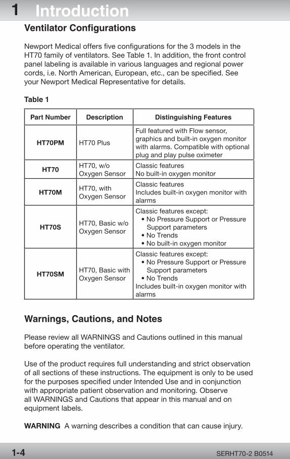
Newport Medical offers five configurations for the 3 models in the HT70 family of ventilators. See Table 1. In addition, the front control panel labeling is available in various languages and regional power cords, i.e. North American, European, etc., can be specified. See your Newport Medical Representative for details.
Table 1
Warnings, Cautions, and Notes
Please review all WARNINGS and Cautions outlined in this manual before operating the ventilator.
Use of the product requires full understanding and strict observation of all sections of these instructions. The equipment is only to be used for the purposes specified under Intended Use and in conjunction with appropriate patient observation and monitoring. Observe all WARNINGS and Cautions that appear in this manual and on equipment labels.
WARNING A warning describes a condition that can cause injury.
Part Number Description Distinguishing Features
HT70PM HT70 Plus
Full featured with Flow sensor, graphics and built-in oxygen monitor with alarms. Compatible with optional plug and play pulse oximeter
HT70 HT70, w/o Oxygen Sensor
Classic featuresNo built-in oxygen monitor
HT70M HT70, with Oxygen Sensor
Classic featuresIncludes built-in oxygen monitor with alarms
HT70S HT70, Basic w/o Oxygen Sensor
Classic features except: • No Pressure Support or Pressure Support parameters • No Trends • No built-in oxygen monitor
HT70SM HT70, Basic with Oxygen Sensor
Classic features except: • No Pressure Support or Pressure Support parameters • No TrendsIncludes built-in oxygen monitor with alarms
OPR360U A05095-1
5
OPR360U A0509 5-1
5
SERHT70-2 B0514 1-5
Introduction 1Caution: A caution describes a condition that can cause damage to equipment.
NOTE: A note emphasizes information that is important or convenient.
General Notes
The Newport HT70 has been designed to accommodate connectivity with nurse call/monitoring systems. Because it is not possible to anticipate every configuration of hardware and software associated with nurse call/monitoring system, it is the user’s responsibility to confirm proper functionality of the system when used in conjunction with the HT70. Verification of alarms, alerts and patient data transmissions is required. If the system performance is not as expected, contact Newport Medical Technical Support for assistance troubleshooting the set-up. Do not use the HT70 ventilator with a nurse call/monitoring system until the functionality of the ventilator/system combination has been confirmed.
General Cautions
Do not place liquids on or near the ventilator.
Damage can occur if the HT70 is exposed to extreme temperatures. Do not store the HT70 in areas where it may be exposed to temperatures below -40° C (-40° F) or above 65° C (149° F).
To avoid the risk of electric shock, the ventilator should not be opened by anyone other than an approved service provider.
General Warnings
The design of the HT70 ventilator, the Operating and Service manuals, and the labeling on the ventilator take into consideration that the purchase and use of the equipment is restricted to trained professionals, and that certain inherent characteristics of the ventilator are known to the operator. Instructions, warnings and caution statements are therefore limited to the specifics of the HT70.
This manual excludes references to various hazards which are obvious to medical professionals and operators of this equipment including consequences of product misuse, and potential adverse effects in patients with abnormal conditions.
Transport of patients with the HT70 requires that medical staff have a good working knowledge of the ventilator’s use and
OPR360U A05095-1
5
OPR360U A05095-1
5
OPR360U A0509 5-1
5
SERHT70-2 B05141-6
1 Introductionproblem resolution. Proper emergency backup equipment must be immediately available during transport.
Product modification or misuse can be dangerous. Newport Medical Instruments, Inc. disclaims all liability for the consequences of product alterations or modifications, as well as for the consequences which might result from the combination of this ventilator with other products, whether supplied by Newport or by other manufacturers, unless such a combination has been specifically endorsed by Newport Medical. There is a risk of explosion if used in the presence of flammable anesthetics.
A patient connected to a ventilator requires the constant attention of trained caregivers to the patient’s condition.
Ventilator alarms are a critical element in the safety net of patient care. It is extremely important for patient safety that caregivers immediately identify and correct alarm violations.
Always have an alternate power source and means of ventilation available when the ventilator is in use so that they are easy to access in case of a mechanical or system problem.
If a fault is detected in the ventilator and its life support functions are in doubt, immediately discontinue use; use an alternative method of ventilation until the fault has been corrected. Contact your service provider immediately.
Do not block the Emergency Gas Intake (on the bottom panel) or the Fresh Gas Intake Port (on the right side panel).
Always use appropriate monitors to ensure sufficient oxygenation and ventilation (such as a pulse oximeter and/or a capnograph) when the HT70 Ventilator is in use on a patient.
The optional Air/Oxygen Entrainment Mixer and Low Flow Oxygen Reservoir are designed to operate with medical grade oxygen.
Ensure that the oxygen source is not empty before and during the use of the optional Air/Oxygen Entrainment Mixer or Low Flow Oxygen Reservoir.
When the optional Air/Oxygen Entrainment Mixer is secured in place, ensure that the oxygen supply is enabled prior to powering the HT70 on to avoid putting stress on the internal pump and compromising gas delivery to the patient.
OPR360U A05095-1
5
OPR360U A0509 5-1
5
SERHT70-2 B0514 1-7
Introduction 1Calibrated oxygen monitoring at clinically appropriate levels is required for patient safety when supplemental oxygen is in use. The optional built-in oxygen sensor on the HT70 allows High and Low O2 alarms to be enabled which can be used to assure proper oxygen delivery.
Always plug the HT70 into an external power supply source whenever it is available, even when HT70 is not in use, to keep the Internal Dual Battery System fully charged and to ensure best battery performance. Check battery capacity on the front panel before detaching from external power.
When installing a replacement Power Pac during battery operation, always ensure that the charge level LED on the replacement pack is green, indicating 90% or higher charge level.
Always ensure that the green External Power LED lights after connecting the ventilator to an external AC or DC power source.
To maintain grounding integrity when using AC power, only connect to properly grounded receptacles.
Use only the Newport supplied AC Power Supply (p/n PWR3204P) with the HT70 ventilator and HT70 Power Pac (p/n BAT3271A).
Always disconnect the external power supply prior to servicing.
After servicing the HT70, it must pass the Operational Verification Procedure (OVP) before it is returned to patient use. See section 6 of the HT70 Service Manual.
Do not use electrically conductive breathing circuits. Always use clean and dry breathing circuits.
Always use a clean, dry filter in the following locations: a standard bacteria filter on the gas output, a prox line (bacteria) filter on the proximal pressure tubing and an intake (bacteria) filter behind the filter cover.
Adding attachments or other components or sub-assemblies to the ventilator breathing circuit system can increase the patient’s work of breathing and/or add resistance to patient exhalation.
Always ensure that the audible alarm loudness level is set at a volume that can be heard by the caregiver. Do not use the ventilator in an environment where audible alarms cannot be heard by the caregivers.
OPR360U A05095-1
5
OPR360U A05095-1
5
OPR360U A0509 5-1
5
SERHT70-2 B05141-8
1 IntroductionThe functioning of this machine may be adversely affected by the operation of other medical equipment, such as high frequency surgical(diathermy) equipment, defibrillators or short-wave therapy equipment in the vicinity.
This device has undergone EMC testing and found to be in conformance with IEC 60601-1-2:2001 and meets the requirement of CISPR11:2004 (Class B), IEC 61000-3-2:2006, and IEC 61000-3-3:1955 + A1:2001 + A2:2005. These requirements are designed to provide reasonable protection against harmful interference in a typical medical installation, as well as in homecare environments. The equipment generates, uses and can radiate radio frequency energy and, if not installed and used in accordance with these instructions, may cause harmful interference to other devices in the vicinity. However, there is no guarantee that interference will not occur in a particular installation. If this equipment does cause harmful interference with other devices, which can be determined by turning the equipment off and on, the user is encouraged to try to correct the interference by one or more of the following measures;
• Reorient or relocate the receiving device.• Increase the separation between the equipment.• Connect the equipment into an outlet on a circuit different from that to which the devices(s) is connected.• Consult the manufacturer or field service technician for help.
Copyright Information
© Copyright 2012 Newport Medical Instruments, Inc. All rights reserved. Newport HT70 Ventilator is manufactured in accordance with Newport Medical Instrument, Inc. proprietary information and is protected under U.S. Patent # 7,654,802.

SpecificationsSection 2:
Sp
ecifications


OPR360U A05095-1
5
OPR360U A0509 5-1
5
SpecificationsSection 2:
Front Panel Buttons - Symbols Version .......... 2-1 Miscellaneous Reference Symbols ................. 2-2 Controls / Monitors ........................................... 2-2Monitor Data Selections ................................... 2-3Front Panel Membrane Buttonsand Indicators .................................................... 2-4Alarms ................................................................ 2-4 User Adjustable Alarms ............................... 2-5 Automatic Alarms ......................................... 2-5Hardware Requirements .................................. 2-7Environment ....................................................... 2-8Size and Weight ................................................. 2-8Factory Default Parameters ............................. 2-9Miscellaneous ................................................... 2-9(optional) Air / Oxygen Entrainment Mixer ..... 2-9(optional) Low Flow Oxygen Reservoir ........... 2-9Regulatory and Agency Standards ............... 2-10

OPR360U A05095-1
5
Page Left Intentionally Blank
OPR360U A05095-1
5
OPR360U A0509 5-1
5
SERHT70-2 B0514 2-1
Specifications 2
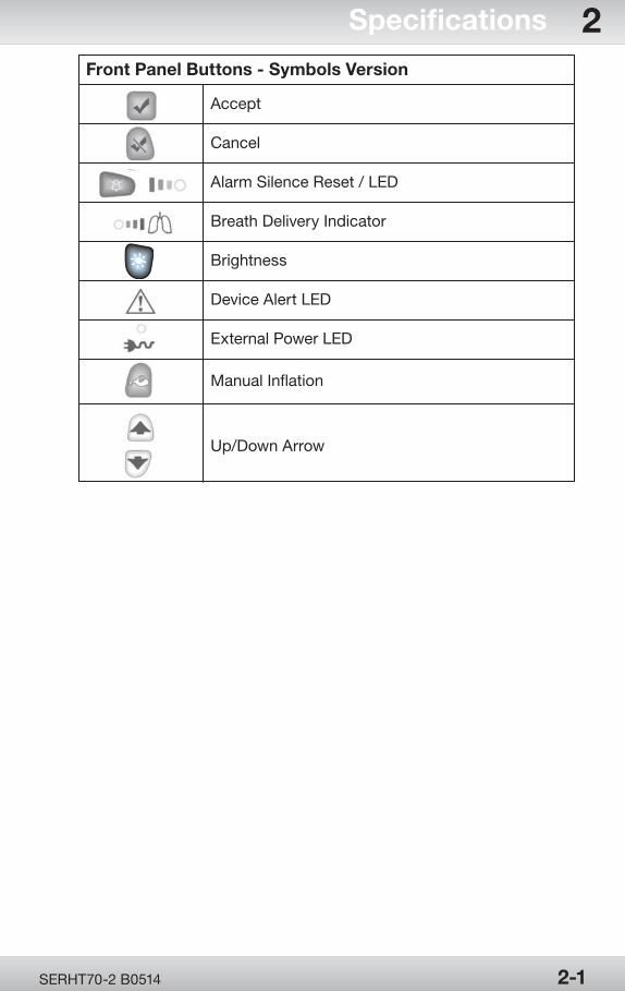
Accept
Cancel
Alarm Silence Reset / LED
Breath Delivery Indicator
Brightness
Device Alert LED
External Power LED
Manual Inflation
Up/Down Arrow
Front Panel Buttons - Symbols Version
OPR360U A05095-1
5
OPR360U A05095-1
5
OPR360U A0509 5-1
5
SERHT70-2 B05142-2
2 Specifications
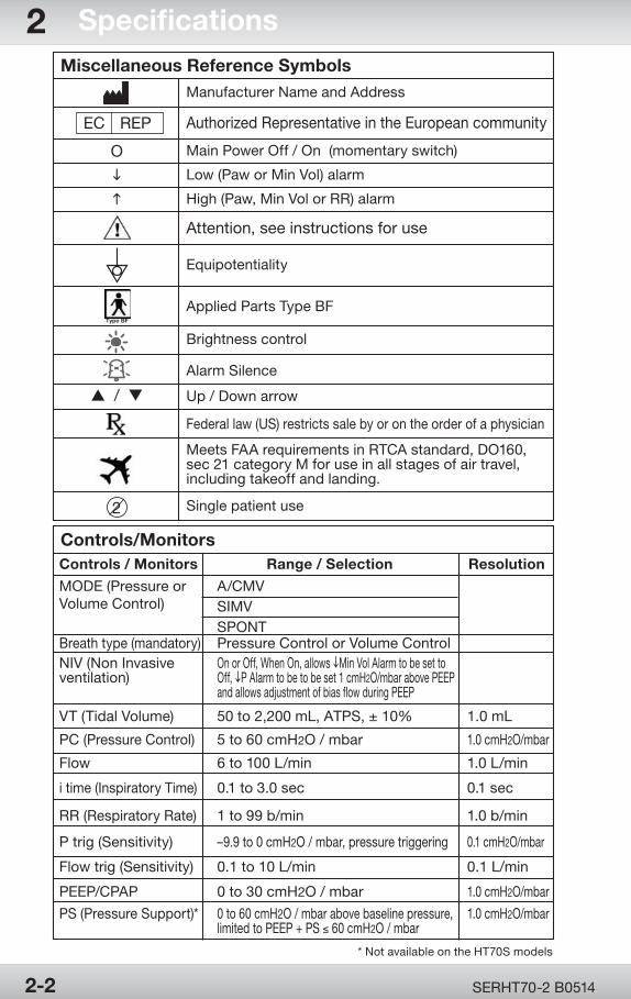
Manufacturer Name and Address
O
i
h
s / t
Authorized Representative in the European community
Main Power Off / On (momentary switch)
Low (Paw or Min Vol) alarm
Equipotentiality
Applied Parts Type BF
Brightness control
Alarm Silence
Up / Down arrow
Single patient use
Federal law (US) restricts sale by or on the order of a physician
Meets FAA requirements in RTCA standard, DO160, sec 21 category M for use in all stages of air travel, including takeoff and landing.
High (Paw, Min Vol or RR) alarm
Attention, see instructions for use
EC REP
Miscellaneous Reference Symbols
Type BF
SIMV
Controls / Monitors Range / Selection Resolution
MODE (Pressure or A/CMVVolume Control)
SPONT
NIV (Non Invasive On or Off, When On, allows iMin Vol Alarm to be set toventilation) Off, iP Alarm to be to be set 1 cmH2O/mbar above PEEP and allows adjustment of bias flow during PEEP
VT (Tidal Volume) 50 to 2,200 mL, ATPS, ± 10% 1.0 mL
PC (Pressure Control) 5 to 60 cmH2O / mbar 1.0 cmH2O/mbar
Flow 6 to 100 L/min 1.0 L/min
Breath type (mandatory) Pressure Control or Volume Control
i time (Inspiratory Time) 0.1 to 3.0 sec 0.1 sec
RR (Respiratory Rate) 1 to 99 b/min 1.0 b/min
P trig (Sensitivity) –9.9 to 0 cmH2O / mbar, pressure triggering 0.1 cmH2O/mbar
PEEP/CPAP 0 to 30 cmH2O / mbar 1.0 cmH2O/mbar
Flow trig (Sensitivity) 0.1 to 10 L/min 0.1 L/min
PS (Pressure Support)* 0 to 60 cmH2O / mbar above baseline pressure, 1.0 cmH2O/mbar limited to PEEP + PS ≤ 60 cmH2O / mbar
Controls/Monitors
* Not available on the HT70S models
2
OPR360U A05095-1
5
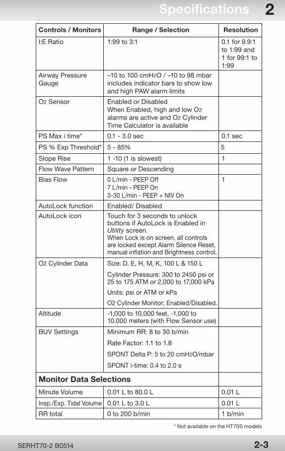
Controls / Monitors Range / Selection Resolution
I:E Ratio 1:99 to 3:1 0.1 for 9.9:1 to 1:99 and 1 for 99:1 to 1:99
Airway Pressure –10 to 100 cmH2O / –10 to 98 mbarGauge includes indicator bars to show low and high PAW alarm limits
Flow Wave Pattern Square or Descending
Bias Flow 0 L/min - PEEP Off 1 7 L/min - PEEP On 3-30 L/min - PEEP + NIV On
O2 Sensor Enabled or Disabled When Enabled, high and low O2
alarms are active and O2 Cylinder Time Calculator is available
PS Max i time* 0.1 - 3.0 sec 0.1 sec
PS % Exp Threshold* 5 - 85% 5
Slope Rise 1 -10 (1 is slowest) 1
AutoLock function Enabled/ Disabled
AutoLock icon Touch for 3 seconds to unlock buttons if AutoLock is Enabled in Utility screen. When Lock is on screen, all controls are locked except Alarm Silence Reset, manual inflation and Brightness control.
O2 Cylinder Data Size: D, E, H, M, K, 100 L & 150 L Cylinder Pressure: 300 to 2450 psi or 25 to 175 ATM or 2,000 to 17,000 kPa
Units: psi or ATM or kPa
O2 Cylinder Monitor; Enabled/Disabled.
Altitude -1,000 to 10,000 feet, -1,000 to 10,000 meters (with Flow Sensor use)
BUV Settings Minimum RR: 8 to 30 b/min
Rate Factor: 1.1 to 1.8
SPONT Delta P: 5 to 20 cmH2O/mbar
SPONT i-time: 0.4 to 2.0 s
Monitor Data Selections
Minute Volume 0.01 L to 80.0 L 0.01 L
Insp./Exp. Tidal Volume 0.01 L to 3.0 L 0.01 L
RR total 0 to 200 b/min 1 b/min
OPR360U A0509 5-1
5
SERHT70-2 B0514 2-3
Specifications 2
* Not available on the HT70S models
OPR360U A05095-1
5
OPR360U A05095-1
5
OPR360U A0509 5-1
5
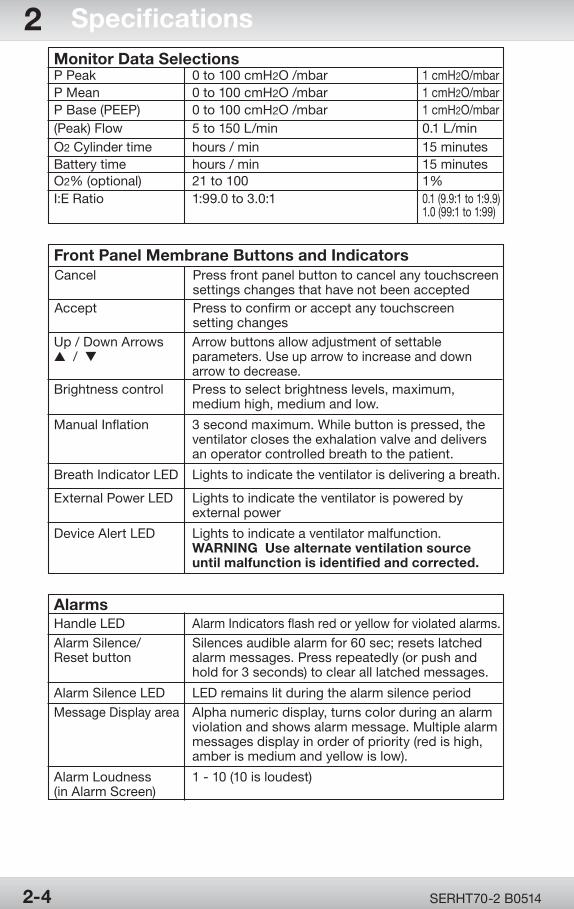
AlarmsHandle LED Alarm Indicators flash red or yellow for violated alarms.
Alarm Silence/ Silences audible alarm for 60 sec; resets latched Reset button alarm messages. Press repeatedly (or push and hold for 3 seconds) to clear all latched messages.
Alarm Silence LED LED remains lit during the alarm silence period
Message Display area Alpha numeric display, turns color during an alarm violation and shows alarm message. Multiple alarm messages display in order of priority (red is high, amber is medium and yellow is low).
Alarm Loudness 1 - 10 (10 is loudest)(in Alarm Screen)
Front Panel Membrane Buttons and Indicators
Up / Down Arrows Arrow buttons allow adjustment of settables / t parameters. Use up arrow to increase and down arrow to decrease.Brightness control Press to select brightness levels, maximum, medium high, medium and low.
Manual Inflation 3 second maximum. While button is pressed, the ventilator closes the exhalation valve and delivers an operator controlled breath to the patient.
Breath Indicator LED Lights to indicate the ventilator is delivering a breath.
External Power LED Lights to indicate the ventilator is powered by external power
Device Alert LED Lights to indicate a ventilator malfunction. WARNING Use alternate ventilation source until malfunction is identified and corrected.
Accept Press to confirm or accept any touchscreen setting changes
Cancel Press front panel button to cancel any touchscreen settings changes that have not been accepted
Monitor Data SelectionsP Peak 0 to 100 cmH2O /mbar 1 cmH2O/mbarP Mean 0 to 100 cmH2O /mbar 1 cmH2O/mbarP Base (PEEP) 0 to 100 cmH2O /mbar 1 cmH2O/mbar(Peak) Flow 5 to 150 L/min 0.1 L/minO2 Cylinder time hours / min 15 minutesBattery time hours / min 15 minutesO2% (optional) 21 to 100 1%I:E Ratio 1:99.0 to 3.0:1 0.1 (9.9:1 to 1:9.9) 1.0 (99:1 to 1:99)
SERHT70-2 B05142-4
2 Specifications
OPR360U A05095-1
5
OPR360U A0509 5-1
5
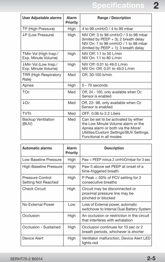
User Adjustable alarms Alarm Range / Description Priority
hP (High Pressure) High 4 to 99 cmH2O / 4 to 99 mbar
iP (Low Pressure) High NIV Off: 3 to 98 cmH2O / 3 to 98 mbar (limited by PEEP + 3); 2 breath delay NIV On: 1 to 98 cmH2O / 1 to 98 mbar (limited by PEEP + 1); 3 breath delay
hMin Vol (High Insp./ High NIV Off: 1.1 to 50 L/minExp. Minute Volume) NIV On: 1.1 to 80 L/min
iMin Vol (Low Insp./ High NIV Off: 0.01 to 49.0 L/min Exp. Minute Volume) NIV On: Off, 0.01 to 49.0 L/min
hRR (High Respiratory Med Off, 30-100 b/minRate)
Apnea High 5 - 70 seconds
hVTE Med OFF, 0.06 to 2.2 Liters
hO2 Med Off, 24 - 100, only available when O2 Sensor is enabled
iO2 Med Off, 22- 98, only available when O2 Sensor is enabled
Backup Ventilation Med Can be set to be activated by either(BUV) the Low Minute Volume alarm or the Apnea alarm or both via the More/ Utilities/Custom Settings/BUV Settings. Functional in all modes
Automatic alarms Alarm Description Priority
Low Baseline Pressure High Paw < PEEP minus 2 cmH2O/mbar for 3 sec
High Baseline Pressure High Paw 5 above set PEEP at onset of a time-triggered breath
Pressure Control High P Peak < 50% of PCV setting for 2Setting Not Reached consecutive breaths
Check Circuit High Circuit may be disconnected or proximal pressure line may be pinched or blocked
No External Power Low Loss of External power, automatic switchover to Internal Dual Battery System
Occlusion High An occlusion or restriction in the circuit that interferes with exhalation
Occlusion - Sustained High Occlusion continues for 10 sec or 2 breath periods, whichever is shorter
Device Alert High Ventilator malfunction, Device Alert LED lights red
SERHT70-2 B0514 2-5
Specifications 2
OPR360U A05095-1
5
OPR360U A05095-1
5
OPR360U A0509 5-1
5
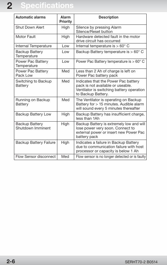
Automatic alarms Alarm Description Priority
Shut Down Alert High Silence by pressing Alarm Silence/Reset buttonMotor Fault High Hardware detected fault in the motor drive circuit has occurredInternal Temperature Low Internal temperature is > 60° C
Backup Battery Low Backup Battery temperature is > 60° CTemperature Power Pac Battery Low Power Pac Battery temperature is > 60° CTemperature Power Pac Battery Med Less than 2 Ah of charge is left onPack Low Power Pac battery pack
Switching to Backup Med Indicates that the Power Pac batteryBattery pack is not available or useable. Ventilator is switching battery operation to Backup Battery.
Running on Backup Med The Ventilator is operating on BackupBattery Battery for > 15 minutes. Audible alarm will sound every 5 minutes thereafter
Backup Battery Low High Backup Battery has insufficient charge, less than 1AhBackup Battery High Backup Battery is extremely low and willShutdown Imminent lose power very soon. Connect to external power or insert new Power Pac battery pack
Backup Battery Failure High Indicates a failure in Backup Battery due to communication failure with host processor or capacity is below 1 AhFlow Sensor disconnect Med Flow sensor is no longer detected or is faulty
SERHT70-2 B05142-6
2 Specifications
OPR360U A05095-1
5
OPR360U A0509 5-1
5
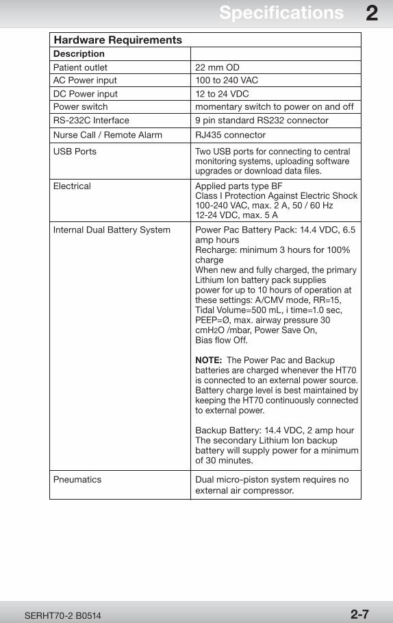
Electrical Applied parts type BF Class I Protection Against Electric Shock 100-240 VAC, max. 2 A, 50 / 60 Hz 12-24 VDC, max. 5 A
Internal Dual Battery System Power Pac Battery Pack: 14.4 VDC, 6.5 amp hours Recharge: minimum 3 hours for 100% charge When new and fully charged, the primary Lithium Ion battery pack supplies power for up to 10 hours of operation at these settings: A/CMV mode, RR=15, Tidal Volume=500 mL, i time=1.0 sec, PEEP=Ø, max. airway pressure 30 cmH2O /mbar, Power Save On, Bias flow Off.
NOTE: The Power Pac and Backup batteries are charged whenever the HT70 is connected to an external power source. Battery charge level is best maintained by keeping the HT70 continuously connected to external power.
Backup Battery: 14.4 VDC, 2 amp hour The secondary Lithium Ion backup battery will supply power for a minimum of 30 minutes.
Description
Patient outlet 22 mm ODAC Power input 100 to 240 VAC
DC Power input 12 to 24 VDCPower switch momentary switch to power on and off
RS-232C Interface 9 pin standard RS232 connector
Nurse Call / Remote Alarm RJ435 connector
USB Ports Two USB ports for connecting to central monitoring systems, uploading software upgrades or download data files.
Hardware Requirements
Pneumatics Dual micro-piston system requires no external air compressor.
SERHT70-2 B0514 2-7
Specifications 2
OPR360U A05095-1
5
OPR360U A05095-1
5
OPR360U A0509 5-1
5
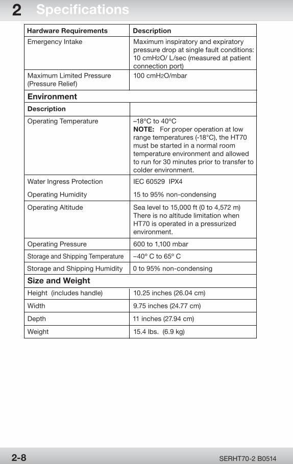
Hardware Requirements Description
Emergency Intake Maximum inspiratory and expiratory pressure drop at single fault conditions: 10 cmH2O/ L/sec (measured at patient connection port)Maximum Limited Pressure 100 cmH2O/mbar(Pressure Relief)
Operating Humidity 15 to 95% non-condensing
Operating Altitude Sea level to 15,000 ft (0 to 4,572 m) There is no altitude limitation when HT70 is operated in a pressurized environment.
Operating Pressure 600 to 1,100 mbar
Storage and Shipping Temperature –40º C to 65º C
Storage and Shipping Humidity 0 to 95% non-condensing
Size and WeightHeight (includes handle) 10.25 inches (26.04 cm)
Width 9.75 inches (24.77 cm)
Depth 11 inches (27.94 cm)
Weight 15.4 lbs. (6.9 kg)
Description
Operating Temperature –18ºC to 40ºC NOTE: For proper operation at low range temperatures (-18°C), the HT70 must be started in a normal room temperature environment and allowed to run for 30 minutes prior to transfer to colder environment.
Water Ingress Protection IEC 60529 IPX4
Environment
SERHT70-2 B05142-8
2 Specifications
OPR360U A05095-1
5
OPR360U A0509 5-1
5
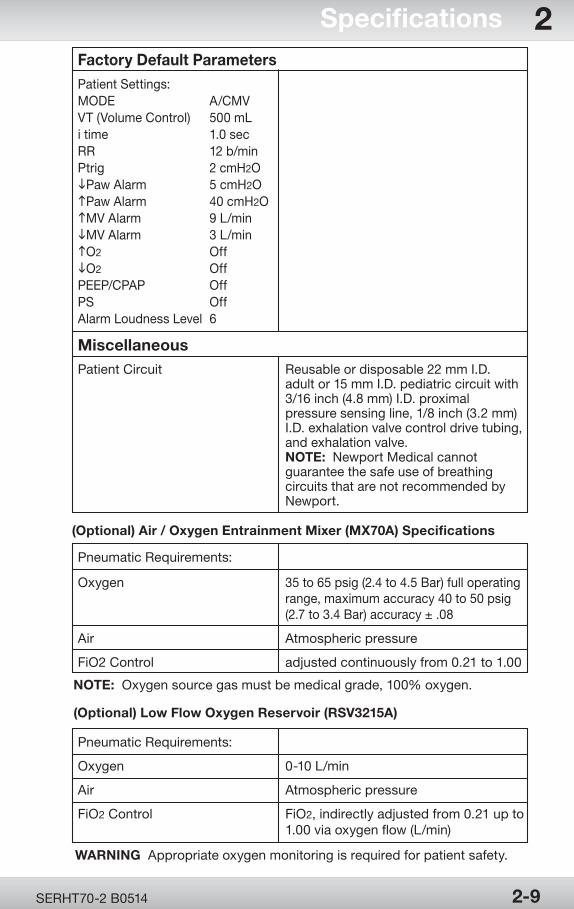
(Optional) Low Flow Oxygen Reservoir (RSV3215A)
WARNING Appropriate oxygen monitoring is required for patient safety.
Pneumatic Requirements:
Oxygen 0-10 L/min
Air Atmospheric pressure
FiO2 Control FiO2, indirectly adjusted from 0.21 up to 1.00 via oxygen flow (L/min)
(Optional) Air / Oxygen Entrainment Mixer (MX70A) Specifications
Pneumatic Requirements:
Oxygen 35 to 65 psig (2.4 to 4.5 Bar) full operating range, maximum accuracy 40 to 50 psig (2.7 to 3.4 Bar) accuracy ± .08
Air Atmospheric pressure
FiO2 Control adjusted continuously from 0.21 to 1.00
NOTE: Oxygen source gas must be medical grade, 100% oxygen.
Factory Default Parameters
Patient Settings:MODE A/CMVVT (Volume Control) 500 mLi time 1.0 secRR 12 b/minPtrig 2 cmH2OiPaw Alarm 5 cmH2O hPaw Alarm 40 cmH2O hMV Alarm 9 L/min iMV Alarm 3 L/min hO2 Off iO2 Off PEEP/CPAP OffPS OffAlarm Loudness Level 6
MiscellaneousPatient Circuit Reusable or disposable 22 mm I.D. adult or 15 mm I.D. pediatric circuit with 3/16 inch (4.8 mm) I.D. proximal pressure sensing line, 1/8 inch (3.2 mm) I.D. exhalation valve control drive tubing, and exhalation valve. NOTE: Newport Medical cannot guarantee the safe use of breathing circuits that are not recommended by Newport.
SERHT70-2 B0514 2-9
Specifications 2
OPR360U A05095-1
5
OPR360U A05095-1
5
OPR360U A0509 5-1
5
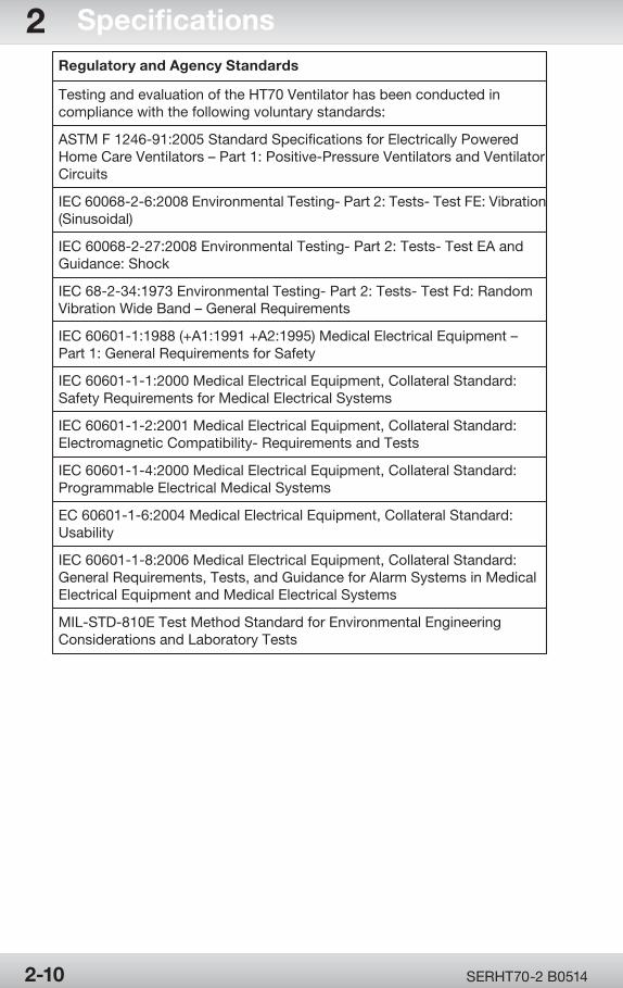
Regulatory and Agency Standards
Testing and evaluation of the HT70 Ventilator has been conducted in compliance with the following voluntary standards:
ASTM F 1246-91:2005 Standard Specifications for Electrically Powered Home Care Ventilators – Part 1: Positive-Pressure Ventilators and Ventilator Circuits
IEC 60068-2-6:2008 Environmental Testing- Part 2: Tests- Test FE: Vibration (Sinusoidal)
IEC 60068-2-27:2008 Environmental Testing- Part 2: Tests- Test EA and Guidance: Shock
IEC 68-2-34:1973 Environmental Testing- Part 2: Tests- Test Fd: Random Vibration Wide Band – General Requirements
IEC 60601-1:1988 (+A1:1991 +A2:1995) Medical Electrical Equipment – Part 1: General Requirements for Safety
IEC 60601-1-1:2000 Medical Electrical Equipment, Collateral Standard: Safety Requirements for Medical Electrical Systems
IEC 60601-1-2:2001 Medical Electrical Equipment, Collateral Standard: Electromagnetic Compatibility- Requirements and Tests
IEC 60601-1-4:2000 Medical Electrical Equipment, Collateral Standard: Programmable Electrical Medical Systems
EC 60601-1-6:2004 Medical Electrical Equipment, Collateral Standard: Usability
IEC 60601-1-8:2006 Medical Electrical Equipment, Collateral Standard: General Requirements, Tests, and Guidance for Alarm Systems in Medical Electrical Equipment and Medical Electrical Systems
MIL-STD-810E Test Method Standard for Environmental Engineering Considerations and Laboratory Tests
SERHT70-2 B05142-10
2 Specifications

Theory of Operation
Section 3:
Theory of Op
eration

OPR360U A05095-1
5
OPR360U A0509 5-1
5
Theory of Operation
Section 3:
Device Description ............................................. 3-1Functional Subsystems Overview .................... 3-2 Pneumatics System ....................................... 3-2 Electronics System .......................................3-3Ventilation Functions Overview ........................ 3-7 Modes of Ventilation...................................... 3-7 Breath Types ................................................ 3-10

OPR360U A05095-1
5
Page Left Intentionally Blank
OPR360U A05095-1
5
OPR360U A0509 5-1
5
SERHT70-2 B0514 3-1
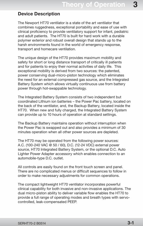
Theory of Operation 3Device Description
The Newport HT70 ventilator is a state of the art ventilator that combines ruggedness, exceptional portability and ease of use with clinical proficiency to provide ventilatory support for infant, pediatric and adult patients. The HT70 is built for hard work with a durable polymer exterior and robust overall design that stands up to the harsh environments found in the world of emergency response, transport and homecare ventilation.
The unique design of the HT70 provides maximum mobility and safety for short or long distance transport of critically ill patients and for patients to enjoy their normal activities of daily life. This exceptional mobility is derived from two sources: the patented, power conserving dual-micro-piston technology which eliminates the need for an external compressed gas source, and the Integrated Battery System which allows virtually continuous use from battery power through hot-swappable technology.
The Integrated Battery System consists of two independent but coordinated Lithium ion batteries – the Power Pac battery, located on the back of the ventilator, and, the Backup Battery, located inside the HT70. When new and fully charged, the Integrated Battery System can provide up to 10 hours of operation at standard settings.
The Backup Battery maintains operation without interruption when the Power Pac is swapped out and also provides a minimum of 30 minutes operation when all other power sources are depleted.
The HT70 may be operated from the following power sources: A.C. (100-240 VAC @ 50 / 60), D.C. (12-24 VDC) external power source, HT70 Integrated Battery System, or the optional D.C. Auto Lighter Power Adapter accessory which enables connection to an automobile-type D.C. outlet.
All controls are easily found on the front touch screen and panel. There are no complicated menus or difficult sequences to follow in order to make necessary adjustments for common operations.
The compact lightweight HT70 ventilator incorporates powerful clinical capability for both invasive and non-invasive applications. The dual micro-piston ability to deliver variable flow enables the HT70 to provide a full range of operating modes and breath types with servo-controlled, leak-compensated PEEP.
OPR360U A05095-1
5
OPR360U A05095-1
5
OPR360U A0509 5-1
5
SERHT70-2 B05143-2
3 Theory of OperationThe HT70 provides monitoring of inspiratory tidal volume (every breath), inspiratory minute volume, total respiratory rate, peak pressure, mean pressure and baseline (PEEP) pressure.
A comprehensive alarm system is built-in to alert the user to violations of user-set or ventilator set safety limits. An optional built-in oxygen monitor with high and low FiO2 alarms may be added.
Gas delivery to the patient may be enriched with oxygen (.21-1.00) using either the optional Low Flow Oxygen Reservoir or high pressure entrainment mixer.
The HT70 has been tested for and meets the requirements for use in a medical evacuation helicopter and fixed wing transport.
Functional Subsystems Overview
Pneumatics System
The Newport HT70 pneumatics system consists of three subsystems: gas delivery, exhalation control, and safety. The gas delivery subsystem drives the movement of air into the lungs of the patient by converting electrical energy into positive air pressure. The exhalation control subsystem changes the breathing cycle from inspiration to expiration and provides positive end expiratory pressure (PEEP). The safety subsystem protects the patient by preventing high pressure and providing a capability to breathe in ambient air in the case of a potential failure of the ventilator. In addition, the safety subsystem is used to measure the air pressure requirements for ventilator safety, control, and monitoring. Refer to the section 8: Diagram 8.1 – Pneumatics System Diagram.
Gas Delivery Subsystem
The gas delivery subsystem draws in air through the cover and inlet filter on the right-hand side of the ventilator. The semi-transparent cover allows the user to directly view the condition of the filter cover to allow for periodic replacement of the inlet filter. The air continues into the muffler, to reach the inlet side of the pump.
The HT70 does not require a gas source unless oxygen (O2) enrichment is desired. For oxygen enrichment, an optional oxygen
OPR360U A05095-1
5
OPR360U A0509 5-1
5
SERHT70-2 B0514 3-3
Theory of Operation 3mixer or low flow oxygen adapter kit may be used. Both items connect to the air intake filter cover and allow the manual adjustment of oxygen enrichment from 21% to 100%. The low flow oxygen adapter provides a low flow of oxygen up to 10 L/min.
Exhalation Valve Control Subsystem
The exhalation valve control subsystem connects within the manifold at the outlet port of the air delivery section. During inspiration, the expiratory valve control circuit actuates the exhalation control On/Off valve to pressurize the exhalation valve drive line. When Positive End-Expiratory Pressure (PEEP) is required, the exhalation control proportional solenoid valve applies pressure to the exhalation valve diaphragm, provides resistance to the expiratory flow, and maintains the patient airway pressure at a set level.
Pneumatics Safety Subsystem
The mechanical relief valve provides the primary high pressure relief function which opens at a pressure of 100 cmH2O. The safety valve provides secondary high pressure relief function by actuating whenever the pressure exceeds 120 cmH2O. In the event of a pump failure, the safety system allows the patient to draw ambient air into the breathing circuit through the emergency intake valve and exhale through the exhalation valve. If an occlusion blocks the circuit for greater than 10 seconds, the safety valve opens and relieves pressure in the patient circuit.
Electronics System
The microprocessor-based design incorporates a Graphical User Interface (GUI), a Single Board Computer (SBC), and the electronics to control the motor/pump, power management, and safety functions of the HT70.
Refer to section 8: Diagram 8.2 – Electronics System Diagram.
Graphical User Interface (GUI) Subsystem
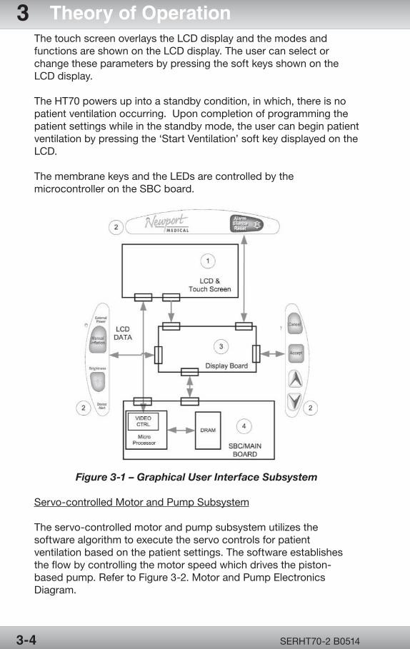
The Graphical User Interface (GUI) consists of a Touch Screen LCD display, membrane panels with embedded discrete Light Emitting Diodes (LED), Display Board, Single Board Computer (SBC) and Main Control Board, and supporting electronics. Refer to the Figure 3-1. Graphical User Interface Subsystem.
OPR360U A05095-1
5
OPR360U A05095-1
5
OPR360U A0509 5-1
5
SERHT70-2 B05143-4
3 Theory of OperationThe touch screen overlays the LCD display and the modes and functions are shown on the LCD display. The user can select or change these parameters by pressing the soft keys shown on the LCD display.
The HT70 powers up into a standby condition, in which, there is no patient ventilation occurring. Upon completion of programming the patient settings while in the standby mode, the user can begin patient ventilation by pressing the ‘Start Ventilation’ soft key displayed on the LCD.
The membrane keys and the LEDs are controlled by the microcontroller on the SBC board.
Figure 3-1 – Graphical User Interface Subsystem
Servo-controlled Motor and Pump Subsystem
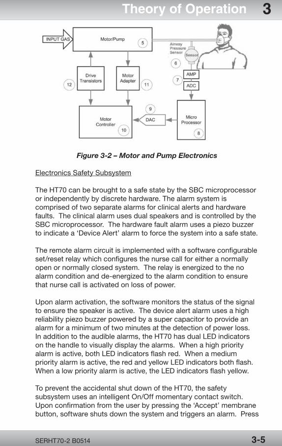
The servo-controlled motor and pump subsystem utilizes the software algorithm to execute the servo controls for patient ventilation based on the patient settings. The software establishes the flow by controlling the motor speed which drives the piston-based pump. Refer to Figure 3-2. Motor and Pump Electronics Diagram.
OPR360U A05095-1
5
OPR360U A0509 5-1
5
SERHT70-2 B0514 3-5
Theory of Operation 3
Figure 3-2 – Motor and Pump Electronics
Electronics Safety Subsystem
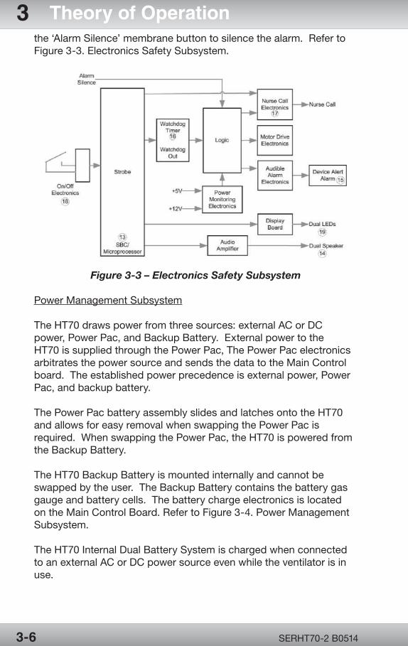
The HT70 can be brought to a safe state by the SBC microprocessor or independently by discrete hardware. The alarm system is comprised of two separate alarms for clinical alerts and hardware faults. The clinical alarm uses dual speakers and is controlled by the SBC microprocessor. The hardware fault alarm uses a piezo buzzer to indicate a ‘Device Alert’ alarm to force the system into a safe state.
The remote alarm circuit is implemented with a software configurable set/reset relay which configures the nurse call for either a normally open or normally closed system. The relay is energized to the no alarm condition and de-energized to the alarm condition to ensure that nurse call is activated on loss of power.
Upon alarm activation, the software monitors the status of the signal to ensure the speaker is active. The device alert alarm uses a high reliability piezo buzzer powered by a super capacitor to provide an alarm for a minimum of two minutes at the detection of power loss. In addition to the audible alarms, the HT70 has dual LED indicators on the handle to visually display the alarms. When a high priority alarm is active, both LED indicators flash red. When a medium priority alarm is active, the red and yellow LED indicators both flash. When a low priority alarm is active, the LED indicators flash yellow.
To prevent the accidental shut down of the HT70, the safety subsystem uses an intelligent On/Off momentary contact switch. Upon confirmation from the user by pressing the ‘Accept’ membrane button, software shuts down the system and triggers an alarm. Press
OPR360U A05095-1
5
OPR360U A05095-1
5
OPR360U A0509 5-1
5
SERHT70-2 B05143-6
3 Theory of Operationthe ‘Alarm Silence’ membrane button to silence the alarm. Refer to Figure 3-3. Electronics Safety Subsystem.
Figure 3-3 – Electronics Safety Subsystem
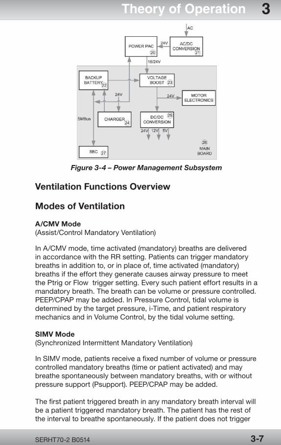
Power Management Subsystem
The HT70 draws power from three sources: external AC or DC power, Power Pac, and Backup Battery. External power to the HT70 is supplied through the Power Pac, The Power Pac electronics arbitrates the power source and sends the data to the Main Control board. The established power precedence is external power, Power Pac, and backup battery.
The Power Pac battery assembly slides and latches onto the HT70 and allows for easy removal when swapping the Power Pac is required. When swapping the Power Pac, the HT70 is powered from the Backup Battery.
The HT70 Backup Battery is mounted internally and cannot be swapped by the user. The Backup Battery contains the battery gas gauge and battery cells. The battery charge electronics is located on the Main Control Board. Refer to Figure 3-4. Power Management Subsystem.
The HT70 Internal Dual Battery System is charged when connected to an external AC or DC power source even while the ventilator is in use.
OPR360U A05095-1
5
OPR360U A0509 5-1
5
SERHT70-2 B0514 3-7
Theory of Operation 3
Figure 3-4 – Power Management Subsystem
Ventilation Functions Overview
Modes of Ventilation
A/CMV Mode(Assist/Control Mandatory Ventilation)
In A/CMV mode, time activated (mandatory) breaths are delivered in accordance with the RR setting. Patients can trigger mandatory breaths in addition to, or in place of, time activated (mandatory) breaths if the effort they generate causes airway pressure to meet the Ptrig or Flow trigger setting. Every such patient effort results in a mandatory breath. The breath can be volume or pressure controlled. PEEP/CPAP may be added. In Pressure Control, tidal volume is determined by the target pressure, i-Time, and patient respiratory mechanics and in Volume Control, by the tidal volume setting.
SIMV Mode(Synchronized Intermittent Mandatory Ventilation)
In SIMV mode, patients receive a fixed number of volume or pressure controlled mandatory breaths (time or patient activated) and may breathe spontaneously between mandatory breaths, with or without pressure support (Psupport). PEEP/CPAP may be added.
The first patient triggered breath in any mandatory breath interval will be a patient triggered mandatory breath. The patient has the rest of the interval to breathe spontaneously. If the patient does not trigger
OPR360U A05095-1
5
OPR360U A05095-1
5
OPR360U A0509 5-1
5
SERHT70-2 B05143-8
3 Theory of Operationthe ventilator, and one complete mandatory breath interval has elapsed, a time triggered mandatory breath is delivered.
A mandatory breath lockout interval is activated whenever the patient triggers a mandatory breath. This limits the number of mandatory breaths (time triggered or patient triggered) the patient receives in 60 seconds to the RR (b/min) setting.
SPONT Mode(Spontaneous Ventilation)
In SPONT mode, mandatory breaths are not delivered but the user can adjust both PEEP/CPAP and pressure support (Psupport) levels. The patient has control over each breath.
When PEEP/CPAP is set above 0, the ventilator mode is CPAP (without Psupport) or Bi-level Positive Airway Pressure (with Psupport). Ensure that Ptrig is set so the HT70 detects all spontaneous patient efforts.
Entries for tidal volume, respiratory rate, i time and Low Paw alarm limit are all inactive in SPONT mode. However, users can preset these parameters for future A/CMV or SIMV operation. As with all HT70 operating modes, Backup Ventilation is activated if the BUV linked alarm is violated.
NIV(Non Invasive Ventilation)
The HT70 can be used for noninvasive ventilation in all modes. Press the NIV button on the left side of the touch screen to toggle ON noninvasive.
When NIV is on the following features are activated to assist with noninvasive ventilation:
• WhenPEEPisinuse,biasflowbecomesadjustablefrom3to 30 L/min to help manage leaks / minimize auto-triggering.
• TheLowMinuteVolumealarmcanbeturnedoffintheAlarms screen
• TheLowPressurealarmcanbesetclosertothebase pressure (within 1 cmH2O /mbar above baseline)
OPR360U A05095-1
5
OPR360U A0509 5-1
5
SERHT70-2 B0514 3-9
Theory of Operation 3BUVBackup Ventilation
Backup Ventilation activates when the currently linked alarm occurs. This function can be linked with the Low Minute Volume (MVI) alarm, the Apnea alarm, or both alarms. During Backup Ventilation the linked alarm(s) will sound and the message window will indicate that Backup Ventilation is in use. There are default Backup Ventilation parameters, but the user may adjust these in the Advanced Screen.
Backup Ventilation is functional in all modes.
Backup Ventilation is not active for 60 seconds after the user adjusts ventilator controls, changes modes or starts ventilation from the Setting condition.
During Backup Ventilation, the Alarm Silence/Reset button can be pressed to silence the audible alarm. This will not cancel Backup Ventilation.
When linked with the Low Minute Volume alarm, Backup Ventilation is based on the exhaled or delivered inspiratory minute volume, depending on whether or not the on-airway flow sensor is in use. The inspiratory minute volume may be different from the expiratory minute volume in some conditions, such as in the case of a patient breathing circuit or airway leak.
Backup Ventilation in A/CMV and SIMV Modes:
The factory default setting for Backup Ventilation in these two modes will increase the respiratory rate by 1.5 times the set rate, up to a maximum of 99 b/min. The minimum breath rate delivered is 15 b/min.
The respiratory rate (RR) will only increase up to a rate that produces a 1:1 I:E ratio even if the calculated Backup Ventilation rate is higher.
Backup Ventilation in Spont Mode:
The factory default setting for Backup Ventilation in the SPONT mode will implement these changes:
SPONT = SIMV mode
Rate = 15 b/min
Pressure Control breath type = 15 cmH2O above set PEEP
i-time = 1.0 sec
OPR360U A05095-1
5
OPR360U A05095-1
5
OPR360U A0509 5-1
5
SERHT70-2 B05143-10
3 Theory of OperationCancellation of Backup Ventilation
User Cancelled
If during Backup Ventilation, the user adjusts any ventilation parameter, Backup Ventilation is suspended for one minute and all user selected ventilation parameters are employed.
Sixty (60) seconds must pass after parameter adjustments before a linked alarm violation will result in Backup Ventilation.
Patient Cancelled
If linked to low minute volume, when minute volume exceeds the Low MV alarm setting by 10%, Backup Ventilation is cancelled. If linked to Apnea Alarm, after 2 minutes of Backup Ventilation it is cancelled. At that time the audible alarm stops, the alarm indicator latches and the HT70 resumes ventilation at the user-selected parameters.
Breath Types
PC(Pressure Control Ventilation)
The HT70 targets and maintains patient airway pressure at the set pressure control level throughout inspiration. Breath termination occurs when (1) the set i time elapses, or (2) Paw exceeds the Pressure Control setting by 8 cmH2O (mbar). Maximum airway pressure never exceeds the user set High P alarm setting.
The target airway pressure for pressure controlled mandatory breaths in A/CMV and SIMV is the display setting above ambient pressure, not above PEEP.
Both time and patient triggered mandatory breaths can be delivered in A/CMV and SIMV Pressure Control operation. During SIMV Pressure Control operation, patients can breathe spontaneously between mandatory breaths with or without pressure support.
When disconnecting the patient circuit during PC/PS ventilation, i.e. for suctioning, the flow may increase in order to compensate for the low pressure. After reconnecting the patient circuit, the flow will automatically readjust to meet the patient’s demand.
OPR360U A05095-1
5
OPR360U A0509 5-1
5
SERHT70-2 B0514 3-11
Theory of Operation 3VC(Volume Control Ventilation)
During Volume Control ventilation, tidal volume can be set for mandatory breaths. If a volume setting is changed while the ventilator is operating, the change takes place in increments over a series of breaths.
When tidal volume is adjusted, inspiratory time remains constant and mandatory flow changes.
If an attempted tidal volume setting results in a flow rate in excess of 100 L/min or less than 6 L/min, flow adjustment ceases, the user is alerted by an audible beep, and a message appears in the Message Display Window. To allow further volume adjustment, change the inspiratory time to set the Flow to meet the need of the patient.

Page Left Intentionally Blank

Cleaning and Maintenance
Section 4:
Cleaning and
Maintenance

OPR360U A05095-1
5
OPR360U A0509 5-1
5
Cleaning and Maintenance
Section 4:
Cleaning and Disinfecting .................................4-1Ventilator ...........................................................4-1Accessories ........................................................4-2 Low Flow Oxygen Reservoir .........................4-2 Air/Oxygen Entrainment Mixer .....................4-2Reusable Breathing Circuits ............................ 4-3Air Intake Filter .................................................. 4-3Proximal Inline Filter ......................................... 4-4Maintenance Guidelines ................................... 4-4 Routine Maintenance ................................... 4-4 6 Month Maintenance .................................. 4-5 12 Month Maintenance ................................. 4-5 24 Month Maintenance ................................ 4-5 15,000 Hour Maintenance ............................ 4-6General Warnings .............................................. 4-6Factory Maintenance or Repair ........................4-7Repacking/Return Information .........................4-7

OPR360U A05095-1
5
Page Left Intentionally Blank
OPR360U A05095-1
5
OPR360U A0509 5-1
5
SERHT70-2 B0514 4-1
Cleaning and Maintenance 4Cleaning and Disinfecting
Use the information in this section in conjunction with hospital policy, physician prescription, Homecare Dealer or accessory manufacturer instructions.
DefinitionsCleaning: A process that uses a medical detergent or alcohol based cleaning solution to remove blood, tissue and other residue. Rinse thoroughly with sterile, distilled water and allow to air dry.
Disinfection: A liquid chemical process that kills microbial organisms.
Sterilization: A process that uses steam autoclave or ethylene oxide (EtO) this is designed to render a product free of viable microorganisms.
Caution: When using liquid chemical agents, closely follow the manufacturer’s recommendations. Prior to use, verify that the agent is compatible with plastics.
WARNING Ethylene Oxide (EtO) is toxic. All accessories MUST be completely dry prior to packaging for ethylene oxide sterilizing. After sterilizing, they must be properly aerated to dissipate residual gas absorbed by the material. Follow the EtO manufacturer’s recommendations for the specific aeration periods required.
Caution: Ethylene Oxide (EtO) may cause superficial crazing of plastic components and will accelerate the aging of rubber components.
Caution: Always inspect breathing circuits and accessories after cleaning, disinfecting or sterilizing to check for deterioration. If the any part is damaged or shows excessive wear, replace with a new part. Do not use cracked or damaged parts.
Ventilator
Wipe clean between patients and as needed while in use. The exterior of the ventilator should be wiped clean with a cloth dampened with a medical detergent, disinfectant or alcohol based cleaning solution.
Caution: Do not use agents that contain acetone, toluene, halogenated hydrocarbons, or strong alkalines on the face panel or ventilator housing.
OPR360U A05095-1
5
OPR360U A05095-1
5
OPR360U A0509 5-1
5
SERHT70-2 B05144-2
4 Cleaning and MaintenanceCaution: Never autoclave or EtO sterilize the HT70 ventilator. These processes will damage the HT70, rendering it unusable.
Accessories
Low Flow Oxygen ReservoirClean and disinfect between patients and as needed while in use, refer to the instructions provided with the oxygen reservoir.
Disassembly from the HT70 ventilator: Remove the Oxygen Reservoir from the HT70 Fresh Gas Intake port. Disconnect the oxygen tubing.
General Cleaning Instructions: Hold the Low Flow Oxygen Reservoir in both hands and twist the top counterclockwise to disassemble. Separate all the parts and clean with soap and water, rinse thoroughly and then air dry.
Caution: Never mount the Low Flow Oxygen Reservoir onto the ventilator when wet.
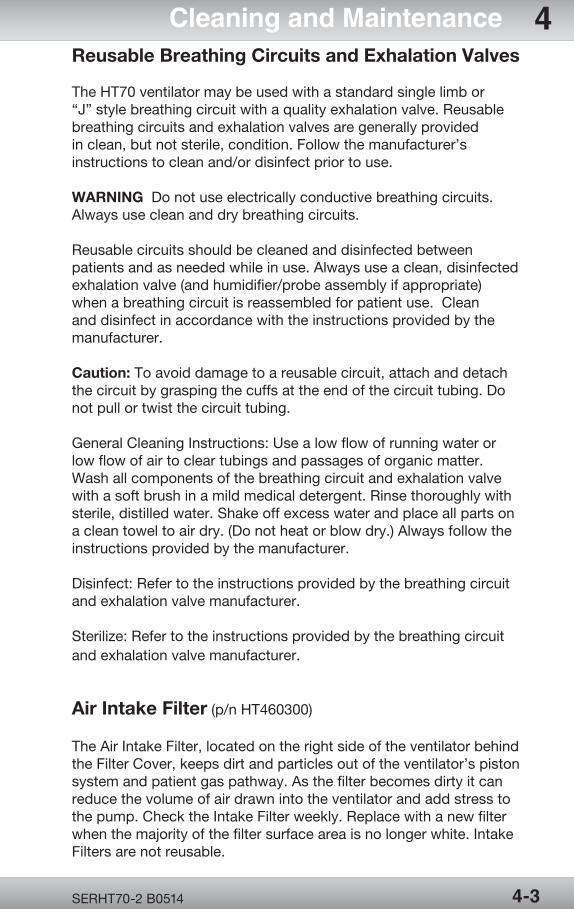
Air/Oxygen Entrainment MixerBetween patients and as needed while in use, the exterior of the mixer and attached hose should be wiped clean with a cloth dampened with a medical detergent, disinfectant or alcohol based cleaning solution.
Check the mixer intake filter (p/n FLT3209P) at setup and at least weekly and replace when dirty.
WARNING Always use a Mixer Intake Filter in the mixer to protect the internal mechanisms from contaminants and preserve the lifespan of your mixer.
WARNING Never reverse the Mixer Filter.
Caution: Do not wash or sterilize the Mixer Filter.
Filter
Oxygen mixer
Cover
OPR360U A05095-1
5
OPR360U A0509 5-1
5
SERHT70-2 B0514 4-3
Cleaning and Maintenance 4Reusable Breathing Circuits and Exhalation Valves
The HT70 ventilator may be used with a standard single limb or “J” style breathing circuit with a quality exhalation valve. Reusable breathing circuits and exhalation valves are generally provided in clean, but not sterile, condition. Follow the manufacturer’s instructions to clean and/or disinfect prior to use.
WARNING Do not use electrically conductive breathing circuits. Always use clean and dry breathing circuits.
Reusable circuits should be cleaned and disinfected between patients and as needed while in use. Always use a clean, disinfected exhalation valve (and humidifier/probe assembly if appropriate) when a breathing circuit is reassembled for patient use. Clean and disinfect in accordance with the instructions provided by the manufacturer.
Caution: To avoid damage to a reusable circuit, attach and detach the circuit by grasping the cuffs at the end of the circuit tubing. Do not pull or twist the circuit tubing.
General Cleaning Instructions: Use a low flow of running water or low flow of air to clear tubings and passages of organic matter. Wash all components of the breathing circuit and exhalation valve with a soft brush in a mild medical detergent. Rinse thoroughly with sterile, distilled water. Shake off excess water and place all parts on a clean towel to air dry. (Do not heat or blow dry.) Always follow the instructions provided by the manufacturer.
Disinfect: Refer to the instructions provided by the breathing circuit and exhalation valve manufacturer.
Sterilize: Refer to the instructions provided by the breathing circuit and exhalation valve manufacturer.
Air Intake Filter (p/n HT460300)
The Air Intake Filter, located on the right side of the ventilator behind the Filter Cover, keeps dirt and particles out of the ventilator’s piston system and patient gas pathway. As the filter becomes dirty it can reduce the volume of air drawn into the ventilator and add stress to the pump. Check the Intake Filter weekly. Replace with a new filter when the majority of the filter surface area is no longer white. Intake Filters are not reusable.
OPR360U A05095-1
5
OPR360U A05095-1
5
OPR360U A0509 5-1
5
SERHT70-2 B05144-4
4 Cleaning and MaintenanceWARNING NEVER operate the HT70 without a clean Air Intake Filter in place. NEVER reverse the Air Intake Filter when dirty.
Proximal Inline Filter (p/n HT6004701 or equivalent)
Check the Proximal (Prox) Inline Filter weekly and replace it at least every 3 months. Discard it and replace with a new filter if it appears to have gotten wet or come in contact with a contaminant. Proximal Inline filters are not reusable. If the filter becomes occluded, replace the filter. The primary indication for this would be a Check Circuit or Prox Line Alarm.
Newport Medical strongly recommends that extra Prox Inline Filters be available at all times when using the HT70 ventilator.
WARNING Always use a Proximal Inline Filter (p/n HT6004701 or equivalent) at the Prox. Line Connector to protect the internal pressure transducers from moisture or other contaminants.
WARNING Never reverse the Proximal Inline Filter.
Caution: Do not wash or sterilize the Prox Inline Filter.
Maintenance Guidelines
Routine Maintenance
3 Perform the Circuit Check each time a fresh circuit/exhalation valve is installed.
3 Check the Air Intake Filter (located behind the Filter Cover) at setup and at least weekly while in use. In some environments, it may need to be checked more often. Replace when the majority of the filter surface area is no longer white. Air Intake Filters are not reusable.
WARNING NEVER reverse the Air Intake Filter when dirty.
3 Check the Prox Inline Filter weekly. Replace with a new filter if it appears to have gotten wet or come in contact with a contaminant. Inline filters are not reusable.
3 Check the Mixer Intake Filter (located behind the Mixer Cover) at setup and at least weekly while in use. In some environments, it may need to be checked more often. Replace when the majority of the filter surface area is no longer white. Mixer Intake Filters are not reusable.
OPR360U A05095-1
5
OPR360U A0509 5-1
5
SERHT70-2 B0514 4-5
Cleaning and Maintenance 43 Inspect the AC Power Adapter on a regular basis for signs of broken or frayed cord or connectors.
3 Inspect the exhalation valve after each cleaning to verify that there are no cracks or damaged surfaces.
3 Wipe down the surface of the ventilator housing regularly to remove any dust that might accumulate.
3 Inspect and when necessary, replace accessories.
3 If service is required, contact Newport Medical or your local equipment provider..
3 To preserve the Internal Dual Battery System life: 1. Whenever possible, plug into external power source to charge the batteries.
2. Use the optional DC Auto Lighter Cable accessory to power the HT70 when traveling by automobile or to connect to an external battery.
See Section 7 of the Operations Manual, Battery Operation for more information on the proper operation of the HT70 Internal Dual Battery System.
6 Month Maintenance
3 Routine maintenance as described above
3 Perform the Quick Check Procedure (described in Section 5 of the Operations Manual)
12 Month Maintenance
3 Routine maintenance as described above
3 Perform the Quick Check Procedure (described in Section 5 of the Operations Manual) 24 Month Maintenance
3 Replace air intake and prox inline filter (HT46300 and HT6004701)
3 Replace the primary integrated battery (Power Pac) (BAT3271A)
3 Replace the secondary internal back up battery (BAT3205A)
3 Replace the oxygen sensor (if installed) (SEN2103P)
OPR360U A05095-1
5
OPR360U A05095-1
5
OPR360U A0509 5-1
5
SERHT70-2 B05144-6
4 Cleaning and Maintenance3 Replace the Coin Battery (BAT3207P)
3 Replace the cooling fan filter (FCT3202P) 3 Calibration and OVP performed by Authorized Service Provider
15,000 Hour Maintenance
3 A comprehensive maintenance should be performed after 15,000 hours of operation. Refer to the HT70 Service Manual, or contact the Newport Medical Technical Service Department for detailed information on the 15,000 Hour Maintenance.
Do not attempt to open or perform any service procedures on the HT70. Only Newport Medical trained technicians are authorized to service the ventilator.
Newport Medical Technical Service Department:Telephone: 800-255-6774 option #4 & option #2Email: [email protected]
General Warnings
Preventive maintenance work, repairs and service may only be performed by Newport Medical trained or factory-authorized personnel.
Always follow accepted hospital procedures or physician instructions for handling equipment contaminated with body fluids.
The ventilator and its accessories must be thoroughly cleaned and disinfected after each patient use. Perform all cleaning and sterilization of external parts and accessories in accordance with established hospital procedures and manufacturer’s instructions.
Certain components of the ventilator, such as the exhalation valve and the front panel, consist of materials that are sensitive to some organic solvents used for cleaning and disinfection (e.g. phenols, halogen releasing compounds, oxygen releasing compounds, and strong organic acids). Exposure to such substances may cause damage that is not immediately recognizable.
The reusable exhalation valve, reusable breathing circuit and other parts that come in direct contact with the patient should be disinfected or sterilized between uses according to hospital policy.
OPR360U A05095-1
5
OPR360U A0509 5-1
5
SERHT70-2 B0514 4-7
Cleaning and Maintenance 4Factory Maintenance or Repair
An authorized Newport Medical Instruments factory-trained technician must do all service or repairs performed on the HT70.
Caution: Always disconnect the external power supply prior to servicing.
Scheduled maintenance or repair services are available from the Newport Technical Service Department. To send your ventilator in for service, see Repackaging /Return Information that follows in this section.
Current pricing for scheduled maintenance and labor rates can be found in Newport Medical Instruments Annual Price List. To obtain a copy, please contact your local Newport Sales Representative or contact our Customer Service Department.
Repacking / Return Information
Use the original packing carton and material to ship the ventilator back to Newport Medical. Or you can contact Newport Medical Customer Service department to order replacement packing material.
Prior to returning your ventilator for service or repair you must obtain a returned goods authorization number (RGA) from our Technical Service Department. Refer to the HT70 Service Manual or contact Technical Service department for complete instructions.
See Contact Information page at the front of this manual for address, phone and website details.

Page Left Intentionally Blank

Service and Repair
Section 5:
Service and
Rep
air

OPR360U A05095-1
5
OPR360U A0509 5-1
5
Service and Repair
Section 5:
General Information ...........................................5-1Tools Required .................................................... 5-1Removal and Replacement of the RearPanel Assembly ..................................................5-2 Rear Panel Assembly ....................................5-2 Single Board Computer (SBC) Assembly ....5-4 Main Control Board (MCB) Assembly ..........5-5 Power Switch Assembly ...............................5-6Removal and Replacement of Top CaseAssembly ...........................................................5-7 Inlet Air Filter ..................................................5-7 Fan Filter and Guard ......................................5-8 Top Case Assembly .......................................5-9 Fan Assembly ............................................... 5-11 Backup Battery ............................................ 5-11 Display Board ............................................... 5-12 Chassis Assembly ....................................... 5-13 Buzzer Assembly ......................................... 5-14 LCD/Touch Screen Display Assembly ....... 5-14 Handle Assembly ......................................... 5-15 Membrane Switch Assemblies ................... 5-16Removal and Replacement of the BaseAssembly ......................................................... 5-17
OPR360U A05095-1
5
OPR360U A0509 5-1
5
OPR360U A05095-1
5
OPR360U A0509 5-1
5
Speaker Assembly ....................................... 5-17 Solenoid Valve Group Assembly ................ 5-18 On/Off Valve .................................................5-20 Safety Valve ..................................................5-20 Pump Assembly ...........................................5-20 Manifold Assembly ......................................5-22
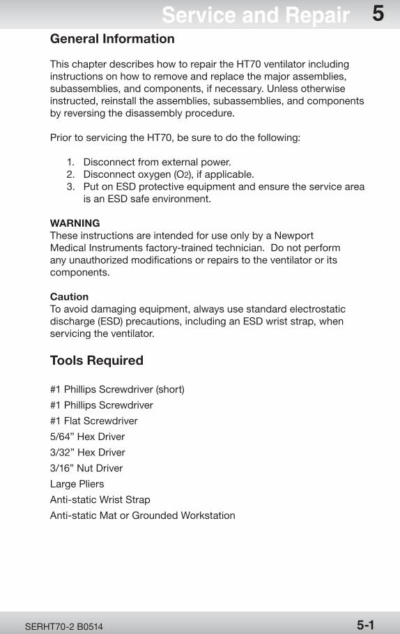
OPR360U A05095-1
5
OPR360U A0509 5-1
5
SERHT70-2 B0514 5-1
Service and Repair 5General Information
This chapter describes how to repair the HT70 ventilator including instructions on how to remove and replace the major assemblies, subassemblies, and components, if necessary. Unless otherwise instructed, reinstall the assemblies, subassemblies, and components by reversing the disassembly procedure.
Prior to servicing the HT70, be sure to do the following:
1. Disconnect from external power. 2. Disconnect oxygen (O2), if applicable. 3. Put on ESD protective equipment and ensure the service area is an ESD safe environment.
WARNING These instructions are intended for use only by a Newport Medical Instruments factory-trained technician. Do not perform any unauthorized modifications or repairs to the ventilator or its components.
Caution To avoid damaging equipment, always use standard electrostatic discharge (ESD) precautions, including an ESD wrist strap, when servicing the ventilator.
Tools Required
#1 Phillips Screwdriver (short)
#1 Phillips Screwdriver
#1 Flat Screwdriver
5/64” Hex Driver
3/32” Hex Driver
3/16” Nut Driver
Large Pliers
Anti-static Wrist Strap
Anti-static Mat or Grounded Workstation
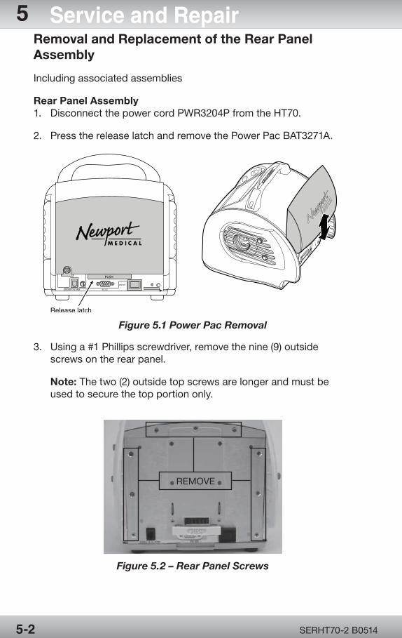
OPR360U A05095-1
5
OPR360U A0509 5-1
5
SERHT70-2 B05145-2
5 Service and RepairRemoval and Replacement of the Rear Panel Assembly
Including associated assemblies
Rear Panel Assembly1. Disconnect the power cord PWR3204P from the HT70.
2. Press the release latch and remove the Power Pac BAT3271A.
Figure 5.1 Power Pac Removal
3. Using a #1 Phillips screwdriver, remove the nine (9) outside screws on the rear panel.
Note: The two (2) outside top screws are longer and must be used to secure the top portion only.
Figure 5.2 – Rear Panel Screws
re nalE
txoP wre
nuaM
la
tl iI
nnf a
o
Bgr hi
tness
Decv eie
Art
l
REMOVE
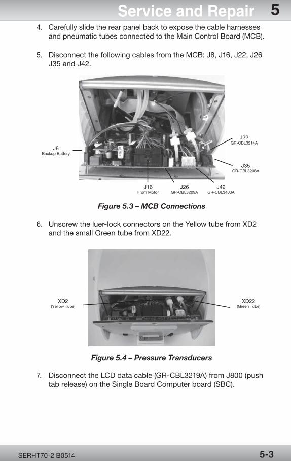
OPR360U A05095-1
5
OPR360U A0509 5-1
5
SERHT70-2 B0514 5-3
Service and Repair 54. Carefully slide the rear panel back to expose the cable harnesses and pneumatic tubes connected to the Main Control Board (MCB).
5. Disconnect the following cables from the MCB: J8, J16, J22, J26 J35 and J42.
Figure 5.3 – MCB Connections
6. Unscrew the luer-lock connectors on the Yellow tube from XD2 and the small Green tube from XD22.
Figure 5.4 – Pressure Transducers
7. Disconnect the LCD data cable (GR-CBL3219A) from J800 (push tab release) on the Single Board Computer board (SBC).
XD2(Yellow Tube)
XD22(Green Tube)
J8Backup Battery
J16From Motor
J26GR-CBL3209A
J42GR-CBL3403A
J35GR-CBL3208A
J22GR-CBL3214A
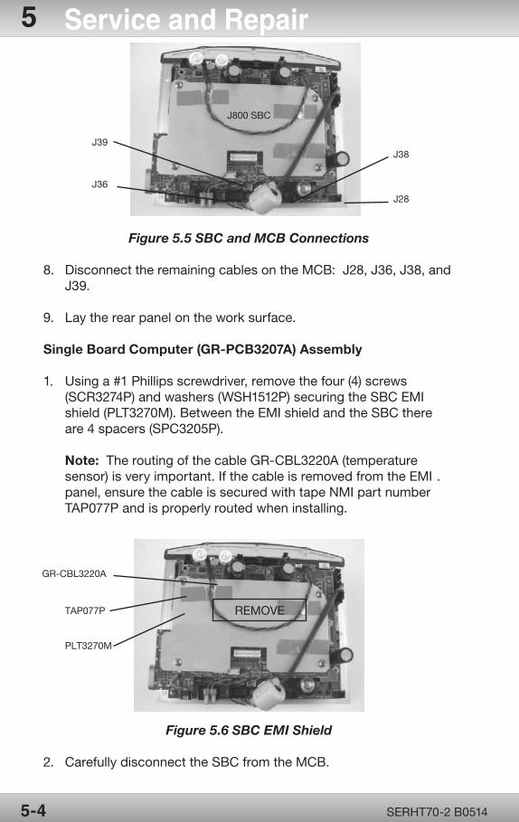
OPR360U A05095-1
5
OPR360U A0509 5-1
5
SERHT70-2 B05145-4
5 Service and Repair
Figure 5.5 SBC and MCB Connections
8. Disconnect the remaining cables on the MCB: J28, J36, J38, and J39.
9. Lay the rear panel on the work surface.
Single Board Computer (GR-PCB3207A) Assembly
1. Using a #1 Phillips screwdriver, remove the four (4) screws (SCR3274P) and washers (WSH1512P) securing the SBC EMI shield (PLT3270M). Between the EMI shield and the SBC there are 4 spacers (SPC3205P).
Note: The routing of the cable GR-CBL3220A (temperature sensor) is very important. If the cable is removed from the EMI . panel, ensure the cable is secured with tape NMI part number TAP077P and is properly routed when installing.
Figure 5.6 SBC EMI Shield
2. Carefully disconnect the SBC from the MCB.
J39
J36
J38
J28
J800 SBC
GR-CBL3220A
TAP077P
PLT3270M
REMOVE
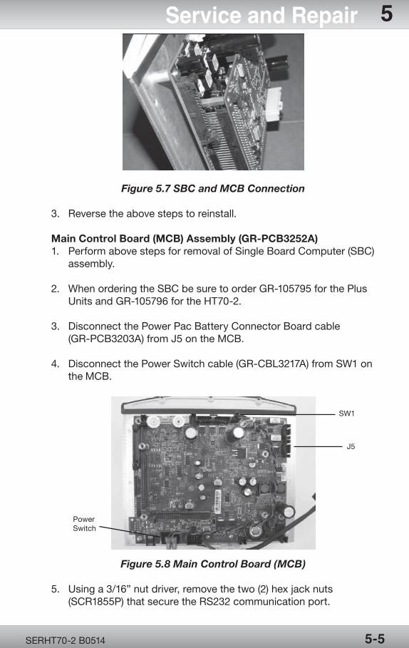
OPR360U A05095-1
5
OPR360U A0509 5-1
5
SERHT70-2 B0514 5-5
Service and Repair 5
Figure 5.7 SBC and MCB Connection
3. Reverse the above steps to reinstall.
Main Control Board (MCB) Assembly (GR-PCB3252A)1. Perform above steps for removal of Single Board Computer (SBC) assembly.
2. When ordering the SBC be sure to order GR-105795 for the Plus Units and GR-105796 for the HT70-2.
3. Disconnect the Power Pac Battery Connector Board cable (GR-PCB3203A) from J5 on the MCB.
4. Disconnect the Power Switch cable (GR-CBL3217A) from SW1 on the MCB.
Figure 5.8 Main Control Board (MCB)
5. Using a 3/16” nut driver, remove the two (2) hex jack nuts (SCR1855P) that secure the RS232 communication port.
PowerSwitch
SW1
J5
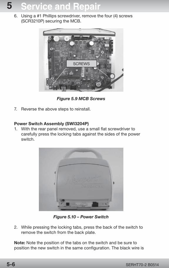
OPR360U A05095-1
5
OPR360U A0509 5-1
5
SERHT70-2 B05145-6
5 Service and Repair6. Using a #1 Phillips screwdriver, remove the four (4) screws (SCR3210P) securing the MCB.
Figure 5.9 MCB Screws
7. Reverse the above steps to reinstall.
Power Switch Assembly (SWI3204P)1. With the rear panel removed, use a small flat screwdriver to carefully press the locking tabs against the sides of the power switch.
Figure 5.10 – Power Switch
2. While pressing the locking tabs, press the back of the switch to remove the switch from the back plate.
Note: Note the position of the tabs on the switch and be sure to position the new switch in the same configuration. The black wire is
SCREWS
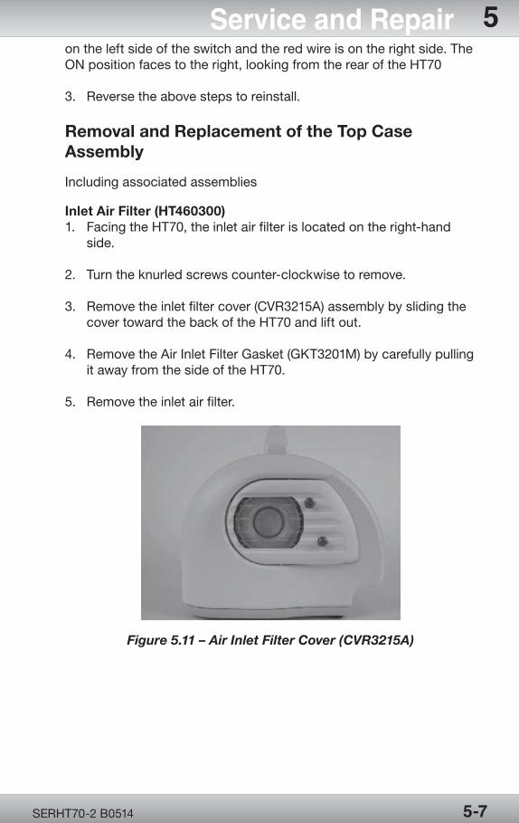
OPR360U A05095-1
5
OPR360U A0509 5-1
5
SERHT70-2 B0514 5-7
Service and Repair 5on the left side of the switch and the red wire is on the right side. The ON position faces to the right, looking from the rear of the HT70
3. Reverse the above steps to reinstall.
Removal and Replacement of the Top Case Assembly
Including associated assemblies
Inlet Air Filter (HT460300)1. Facing the HT70, the inlet air filter is located on the right-hand side.
2. Turn the knurled screws counter-clockwise to remove.
3. Remove the inlet filter cover (CVR3215A) assembly by sliding the cover toward the back of the HT70 and lift out.
4. Remove the Air Inlet Filter Gasket (GKT3201M) by carefully pulling it away from the side of the HT70.
5. Remove the inlet air filter.
Figure 5.11 – Air Inlet Filter Cover (CVR3215A)
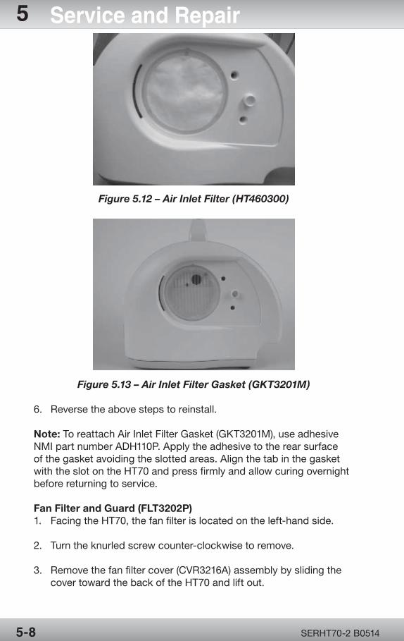
OPR360U A05095-1
5
OPR360U A0509 5-1
5
SERHT70-2 B05145-8
5 Service and Repair
Figure 5.12 – Air Inlet Filter (HT460300)
Figure 5.13 – Air Inlet Filter Gasket (GKT3201M)
6. Reverse the above steps to reinstall.
Note: To reattach Air Inlet Filter Gasket (GKT3201M), use adhesive NMI part number ADH110P. Apply the adhesive to the rear surface of the gasket avoiding the slotted areas. Align the tab in the gasket with the slot on the HT70 and press firmly and allow curing overnight before returning to service.
Fan Filter and Guard (FLT3202P)1. Facing the HT70, the fan filter is located on the left-hand side.
2. Turn the knurled screw counter-clockwise to remove.
3. Remove the fan filter cover (CVR3216A) assembly by sliding the cover toward the back of the HT70 and lift out.
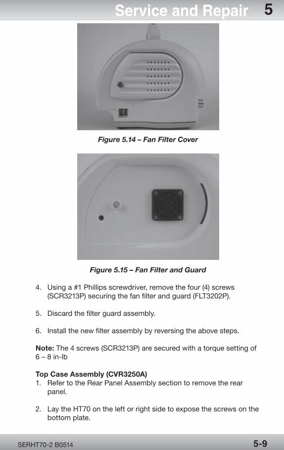
OPR360U A05095-1
5
OPR360U A0509 5-1
5
SERHT70-2 B0514 5-9
Service and Repair 5
Figure 5.14 – Fan Filter Cover
Figure 5.15 – Fan Filter and Guard
4. Using a #1 Phillips screwdriver, remove the four (4) screws (SCR3213P) securing the fan filter and guard (FLT3202P).
5. Discard the filter guard assembly.
6. Install the new filter assembly by reversing the above steps.
Note: The 4 screws (SCR3213P) are secured with a torque setting of 6 – 8 in-lb
Top Case Assembly (CVR3250A)1. Refer to the Rear Panel Assembly section to remove the rear panel.
2. Lay the HT70 on the left or right side to expose the screws on the bottom plate.
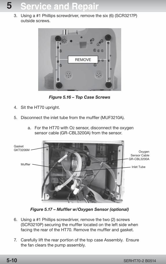
OPR360U A05095-1
5
OPR360U A0509 5-1
5
SERHT70-2 B05145-10
5 Service and Repair3. Using a #1 Phillips screwdriver, remove the six (6) (SCR3217P) outside screws.
Figure 5.16 – Top Case Screws
4. Sit the HT70 upright.
5. Disconnect the inlet tube from the muffler (MUF3210A).
a. For the HT70 with O2 sensor, disconnect the oxygen sensor cable (GR-CBL3200A) from the sensor.
Figure 5.17 – Muffler w/Oxygen Sensor (optional)
6. Using a #1 Phillips screwdriver, remove the two (2) screws (SCR3210P) securing the muffler located on the left side when facing the rear of the HT70. Remove the muffler and gasket.
7. Carefully lift the rear portion of the top case Assembly. Ensure the fan clears the pump assembly.
REMOVE
GasketGKT3206M
Muffler
OxygenSensor Cable
GR-CBL3200A
Inlet Tube
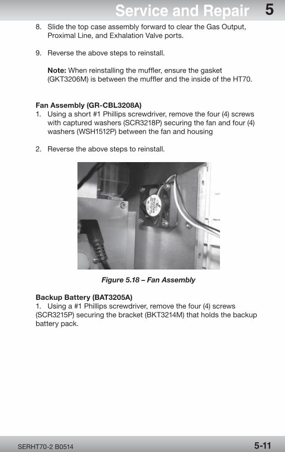
OPR360U A05095-1
5
OPR360U A0509 5-1
5
SERHT70-2 B0514 5-11
Service and Repair 58. Slide the top case assembly forward to clear the Gas Output, Proximal Line, and Exhalation Valve ports.
9. Reverse the above steps to reinstall.
Note: When reinstalling the muffler, ensure the gasket (GKT3206M) is between the muffler and the inside of the HT70.
Fan Assembly (GR-CBL3208A)1. Using a short #1 Phillips screwdriver, remove the four (4) screws with captured washers (SCR3218P) securing the fan and four (4) washers (WSH1512P) between the fan and housing
2. Reverse the above steps to reinstall.
Figure 5.18 – Fan Assembly
Backup Battery (BAT3205A)1. Using a #1 Phillips screwdriver, remove the four (4) screws (SCR3215P) securing the bracket (BKT3214M) that holds the backup battery pack.
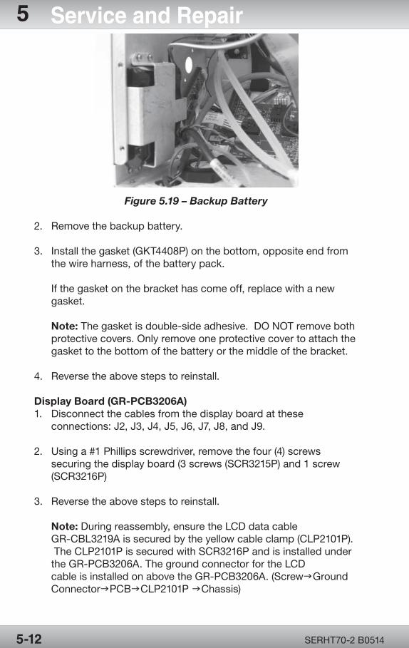
OPR360U A05095-1
5
OPR360U A0509 5-1
5
SERHT70-2 B05145-12
5 Service and Repair
Figure 5.19 – Backup Battery
2. Remove the backup battery.
3. Install the gasket (GKT4408P) on the bottom, opposite end from the wire harness, of the battery pack.
If the gasket on the bracket has come off, replace with a new gasket.
Note: The gasket is double-side adhesive. DO NOT remove both protective covers. Only remove one protective cover to attach the gasket to the bottom of the battery or the middle of the bracket.
4. Reverse the above steps to reinstall.
Display Board (GR-PCB3206A)1. Disconnect the cables from the display board at these connections: J2, J3, J4, J5, J6, J7, J8, and J9.
2. Using a #1 Phillips screwdriver, remove the four (4) screws securing the display board (3 screws (SCR3215P) and 1 screw (SCR3216P)
3. Reverse the above steps to reinstall.
Note: During reassembly, ensure the LCD data cable GR-CBL3219A is secured by the yellow cable clamp (CLP2101P). The CLP2101P is secured with SCR3216P and is installed under the GR-PCB3206A. The ground connector for the LCD cable is installed on above the GR-PCB3206A. (ScrewgGround ConnectorgPCBgCLP2101P gChassis)
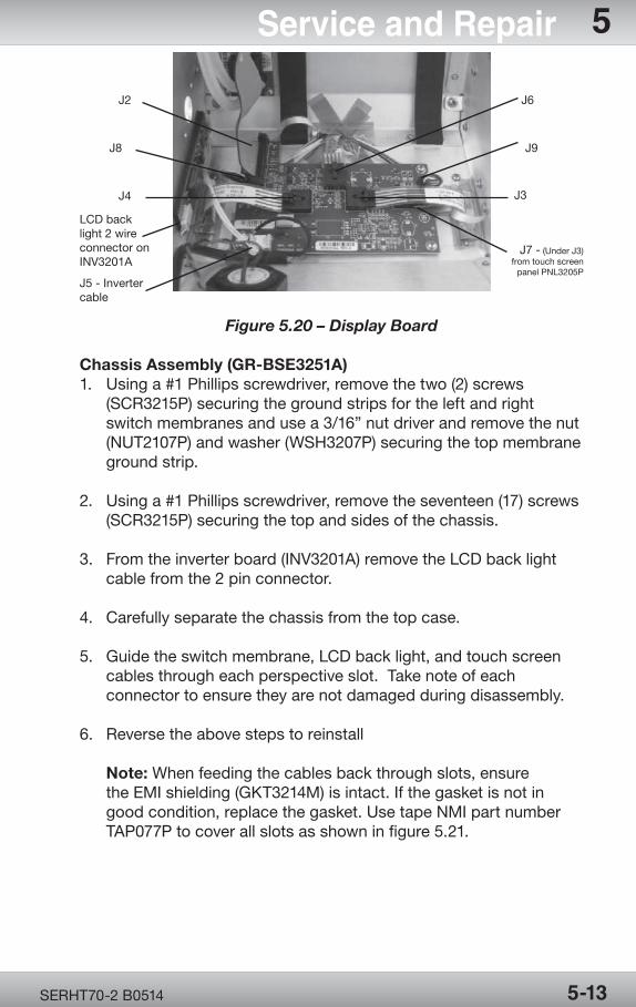
OPR360U A05095-1
5
OPR360U A0509 5-1
5
SERHT70-2 B0514 5-13
Service and Repair 5
Figure 5.20 – Display Board
Chassis Assembly (GR-BSE3251A)1. Using a #1 Phillips screwdriver, remove the two (2) screws (SCR3215P) securing the ground strips for the left and right switch membranes and use a 3/16” nut driver and remove the nut (NUT2107P) and washer (WSH3207P) securing the top membrane ground strip.
2. Using a #1 Phillips screwdriver, remove the seventeen (17) screws (SCR3215P) securing the top and sides of the chassis.
3. From the inverter board (INV3201A) remove the LCD back light cable from the 2 pin connector.
4. Carefully separate the chassis from the top case.
5. Guide the switch membrane, LCD back light, and touch screen cables through each perspective slot. Take note of each connector to ensure they are not damaged during disassembly.
6. Reverse the above steps to reinstall
Note: When feeding the cables back through slots, ensure the EMI shielding (GKT3214M) is intact. If the gasket is not in good condition, replace the gasket. Use tape NMI part number TAP077P to cover all slots as shown in figure 5.21.
LCD backlight 2 wireconnector on INV3201A
J5 - Inverter cable
J4
J8
J2
J7 - (Under J3)from touch screen
panel PNL3205P
J3
J9
J6
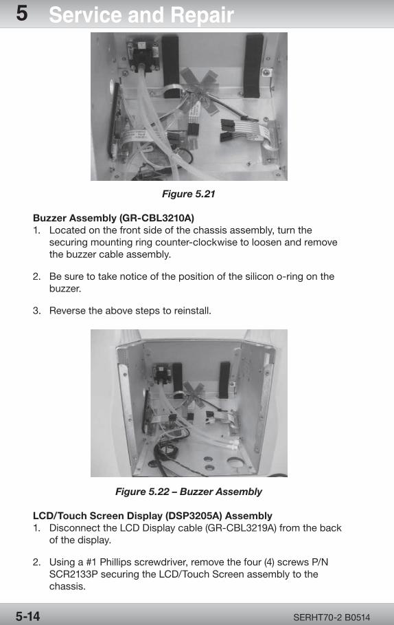
OPR360U A05095-1
5
OPR360U A0509 5-1
5
SERHT70-2 B05145-14
5 Service and Repair
Figure 5.21
Buzzer Assembly (GR-CBL3210A)1. Located on the front side of the chassis assembly, turn the securing mounting ring counter-clockwise to loosen and remove the buzzer cable assembly.
2. Be sure to take notice of the position of the silicon o-ring on the buzzer.
3. Reverse the above steps to reinstall.
Figure 5.22 – Buzzer Assembly
LCD/Touch Screen Display (DSP3205A) Assembly1. Disconnect the LCD Display cable (GR-CBL3219A) from the back of the display.
2. Using a #1 Phillips screwdriver, remove the four (4) screws P/N SCR2133P securing the LCD/Touch Screen assembly to the chassis.
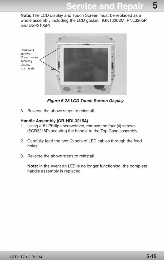
OPR360U A05095-1
5
OPR360U A0509 5-1
5
SERHT70-2 B0514 5-15
Service and Repair 5Note: The LCD display and Touch Screen must be replaced as a whole assembly including the LCD gasket. (GKT3208M, PNL3205P and DSP2105P)
Figure 5.23 LCD Touch Screen Display
3. Reverse the above steps to reinstall.
Handle Assembly (GR-HDL3215A)1. Using a #1 Phillips screwdriver, remove the four (4) screws (SCR3216P) securing the handle to the Top Case assembly.
2. Carefully feed the two (2) sets of LED cables through the feed holes.
3. Reverse the above steps to reinstall.
Note: In the event an LED is no longer functioning, the complete handle assembly is replaced.
Remove 4screws(2 each side)securingdisplayto chassis
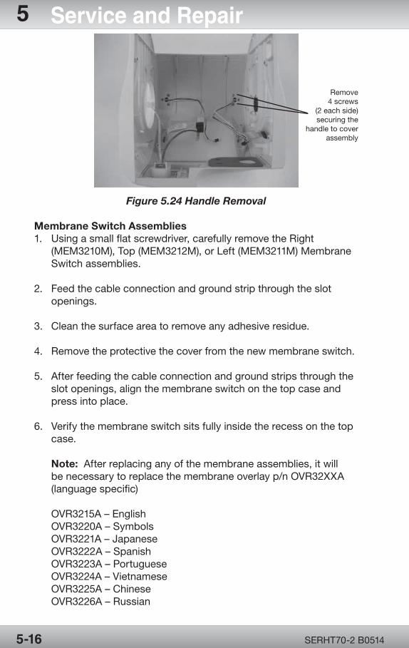
OPR360U A05095-1
5
OPR360U A0509 5-1
5
SERHT70-2 B05145-16
5 Service and Repair
Figure 5.24 Handle Removal
Membrane Switch Assemblies1. Using a small flat screwdriver, carefully remove the Right (MEM3210M), Top (MEM3212M), or Left (MEM3211M) Membrane Switch assemblies.
2. Feed the cable connection and ground strip through the slot openings.
3. Clean the surface area to remove any adhesive residue.
4. Remove the protective the cover from the new membrane switch.
5. After feeding the cable connection and ground strips through the slot openings, align the membrane switch on the top case and press into place.
6. Verify the membrane switch sits fully inside the recess on the top case.
Note: After replacing any of the membrane assemblies, it will be necessary to replace the membrane overlay p/n OVR32XXA (language specific)
OVR3215A – EnglishOVR3220A – SymbolsOVR3221A – JapaneseOVR3222A – SpanishOVR3223A – PortugueseOVR3224A – VietnameseOVR3225A – ChineseOVR3226A – Russian
Remove4 screws
(2 each side) securing the
handle to cover assembly
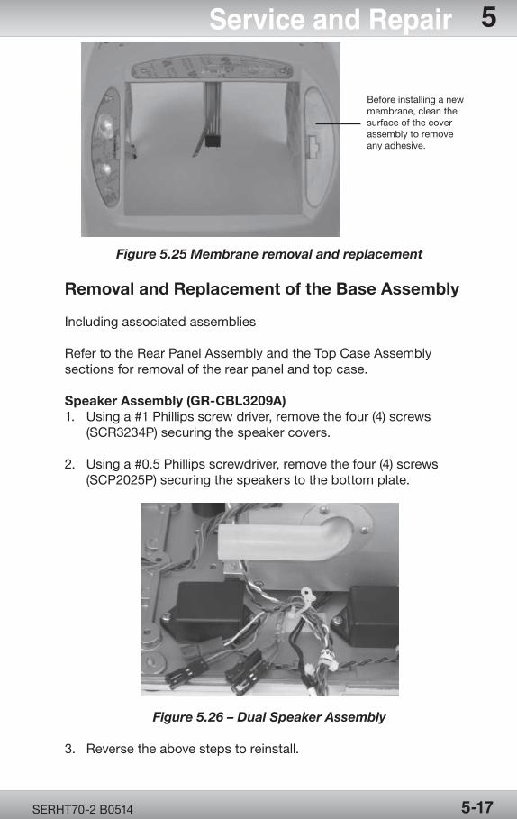
OPR360U A05095-1
5
OPR360U A0509 5-1
5
SERHT70-2 B0514 5-17
Service and Repair 5
Figure 5.25 Membrane removal and replacement
Removal and Replacement of the Base Assembly
Including associated assemblies
Refer to the Rear Panel Assembly and the Top Case Assembly sections for removal of the rear panel and top case.
Speaker Assembly (GR-CBL3209A)1. Using a #1 Phillips screw driver, remove the four (4) screws (SCR3234P) securing the speaker covers.
2. Using a #0.5 Phillips screwdriver, remove the four (4) screws (SCP2025P) securing the speakers to the bottom plate.
Figure 5.26 – Dual Speaker Assembly
3. Reverse the above steps to reinstall.
Before installing a new membrane, clean the surface of the cover assembly to remove any adhesive.
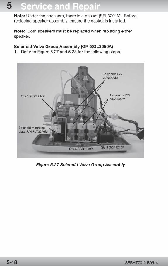
OPR360U A05095-1
5
OPR360U A0509 5-1
5
SERHT70-2 B05145-18
5 Service and RepairNote: Under the speakers, there is a gasket (SEL3201M). Before replacing speaker assembly, ensure the gasket is installed.
Note: Both speakers must be replaced when replacing either speaker.
Solenoid Valve Group Assembly (GR-SOL3250A)1. Refer to Figure 5.27 and 5.28 for the following steps.
Figure 5.27 Solenoid Valve Group Assembly
Qty 2 SCR3234P
Solenoid mountingplate P/N PLT3276M
Qty 6 SCR3219P Qty 4 SCR3215P
Solenoids P/N VLV3229M
Solenoids P/N VLV3226M
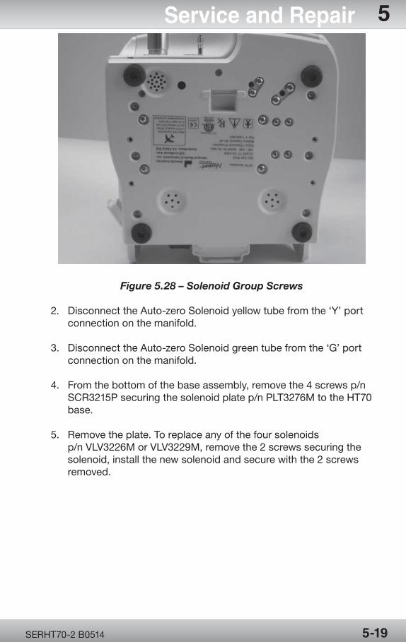
OPR360U A05095-1
5
OPR360U A0509 5-1
5
SERHT70-2 B0514 5-19
Service and Repair 5
Figure 5.28 – Solenoid Group Screws
2. Disconnect the Auto-zero Solenoid yellow tube from the ‘Y’ port connection on the manifold.
3. Disconnect the Auto-zero Solenoid green tube from the ‘G’ port connection on the manifold.
4. From the bottom of the base assembly, remove the 4 screws p/n SCR3215P securing the solenoid plate p/n PLT3276M to the HT70 base.
5. Remove the plate. To replace any of the four solenoids p/n VLV3226M or VLV3229M, remove the 2 screws securing the solenoid, install the new solenoid and secure with the 2 screws removed.
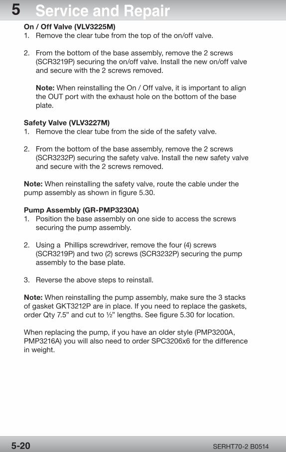
OPR360U A05095-1
5
OPR360U A0509 5-1
5
SERHT70-2 B05145-20
5 Service and RepairOn / Off Valve (VLV3225M)1. Remove the clear tube from the top of the on/off valve.
2. From the bottom of the base assembly, remove the 2 screws (SCR3219P) securing the on/off valve. Install the new on/off valve and secure with the 2 screws removed.
Note: When reinstalling the On / Off valve, it is important to align the OUT port with the exhaust hole on the bottom of the base plate.
Safety Valve (VLV3227M)1. Remove the clear tube from the side of the safety valve.
2. From the bottom of the base assembly, remove the 2 screws (SCR3232P) securing the safety valve. Install the new safety valve and secure with the 2 screws removed.
Note: When reinstalling the safety valve, route the cable under the pump assembly as shown in figure 5.30.
Pump Assembly (GR-PMP3230A)1. Position the base assembly on one side to access the screws securing the pump assembly.
2. Using a Phillips screwdriver, remove the four (4) screws (SCR3219P) and two (2) screws (SCR3232P) securing the pump assembly to the base plate.
3. Reverse the above steps to reinstall.
Note: When reinstalling the pump assembly, make sure the 3 stacks of gasket GKT3212P are in place. If you need to replace the gaskets, order Qty 7.5” and cut to ½” lengths. See figure 5.30 for location.
When replacing the pump, if you have an older style (PMP3200A, PMP3216A) you will also need to order SPC3206x6 for the difference in weight.
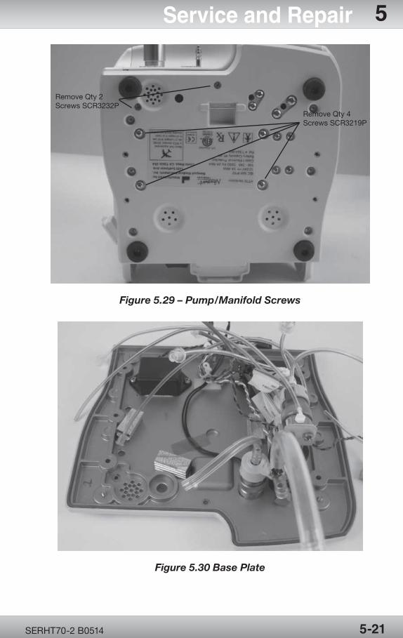
OPR360U A05095-1
5
OPR360U A0509 5-1
5
SERHT70-2 B0514 5-21
Service and Repair 5
Figure 5.29 – Pump/Manifold Screws
Figure 5.30 Base Plate
Remove Qty 4 Screws SCR3219P
Remove Qty 2 Screws SCR3232P
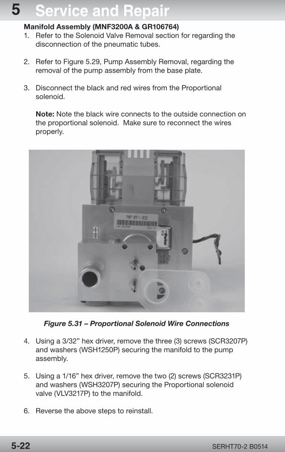
OPR360U A05095-1
5
OPR360U A0509 5-1
5
SERHT70-2 B05145-22
5 Service and RepairManifold Assembly (MNF3200A & GR106764)1. Refer to the Solenoid Valve Removal section for regarding the disconnection of the pneumatic tubes.
2. Refer to Figure 5.29, Pump Assembly Removal, regarding the removal of the pump assembly from the base plate.
3. Disconnect the black and red wires from the Proportional solenoid.
Note: Note the black wire connects to the outside connection on the proportional solenoid. Make sure to reconnect the wires properly.
Figure 5.31 – Proportional Solenoid Wire Connections
4. Using a 3/32” hex driver, remove the three (3) screws (SCR3207P) and washers (WSH1250P) securing the manifold to the pump assembly.
5. Using a 1/16” hex driver, remove the two (2) screws (SCR3231P) and washers (WSH3207P) securing the Proportional solenoid valve (VLV3217P) to the manifold.
6. Reverse the above steps to reinstall.

OPR360U A05095-1
5
OPR360U A0509 5-1
5
SERHT70-2 B0514 5-23
Service and Repair 5Note: When reinstalling the Proportional solenoid valve to the manifold and the manifold to the pump assembly, ensure the o-rings (ORG200P) are fully seated to avoid any possible damage to the o-rings.
Note: The gasket (GKT3254M) is installed over the gas outlet and Prox and Exh fittings.

Page Left Intentionally Blank

Performance Verification
Section 6:
Perform
ance Verification

OPR360U A05095-1
5
OPR360U A0509 5-1
5
Performance Verification
Section 6:
General Information ........................................... 6-1Test Equipment ................................................... 6-1Quick Check ....................................................... 6-1 Introduction .................................................... 6-1 Pre-test Inspection ........................................6-2 Setup and Circuit Check ...............................6-2 Standard Test Settings .................................6-4 Quick Check Procedure ................................6-5Calibration Procedures......................................6-8 Introduction ....................................................6-8 Equipment Setup ...........................................6-8 Pressure Transducer Calibration .................6-8 Motor Speed Calibration ............................. 6-11 Pump Leak Calibration................................ 6-11 FiO2 Sensor Calibration .............................. 6-12 LCD Calibration............................................ 6-12 Flow Sensor Board GR-PCB3212A Calibration .................................................... 6-12Operational Verification Procedure (OVP) ..... 6-13 Electrical Safety Test (EST) ........................ 6-13 Equipment Setup ......................................... 6-13 Front Panel Test ........................................... 6-14
OPR360U A05095-1
5
OPR360U A0509 5-1
5
AC Power Loss and Shutdown Buzzer Alarm Test .................................................... 6-14 Circuit Check ............................................... 6-14 LED/Solenoid Check ................................... 6-15 Pressure Relief Valve Test .......................... 6-17 Pressure Verification Test ........................... 6-18 System Leak Test ........................................ 6-18 Flow Measurement ...................................... 6-19 Emergency Intake Valve Test ..................... 6-19 Patient Effort Indicator Test ....................... 6-19 Pressure Control and PEEP Test ...............6-20 FiO2 Verification Test ...................................6-21 Volume Control Test ....................................6-21 Manual Inflation Test ...................................6-22 Pressure Alarm Test ....................................6-22 Integrated Battery System Check .............6-24
OPR360U A05095-1
5
OPR360U A0509 5-1
5
SERHT70-2 B0514 6-1
Performance Verification 6General Information
This chapter describes how to perform a Quick Check, calibration, and Operational Verification Procedure of the HT70 ventilator. These performance checks ensure the HT70 is in proper operating condition after a service and/or repair has been performed.
WARNING Do not use the HT70 ventilator unless it passes the OVP.
Test Equipment Required
• CertifiedcalibrationanalyzerPTS2000orequivalent • OxygenAnalyzer • NewportMedicaldisposablepatientbreathingcircuit (BCD43811P)orequivalent • Adult500mLtestlung(LNG800PorLNG600AwithanRp20 parabolicairwayrestrictor) • ParabolicAirwayRestrictors–Rp20&Rp50 • Medicalgradeoxygensource • Cap(CAP100P)tooccludethepatientcircuitY-pieceor equivalent(Qty2) • 20ccLockingSyringe(TOL1952P) • T-connector(TOL200A) • OxygenReservoir(RSV3215A)andFlowMeter(FLW300A)
CautionTheaccuracyofalltestequipment(electronicorpneumatic)used for verification or calibration procedures should be certified annuallybyatestinglaboratorybeforeuse.
Quick Check
Introduction
ThisprocedureisintendedtoassistqualifiedoperatorsestablisharoutineprogramforverifyingproperHT70operation.PerformtheQuick Check procedure before the first patient use, between patient uses,every6months.
HOMECAREPROVIDERS:ThisprocedureshouldbeperformedpriortodeliveryoftheHT70toapatient’shomeandevery6months.
NOTE:IfPowerSaveisOn,thescreenwillgotosleep(goblank)whennotusedfortwominutes.Justtouchanybuttonorthescreenanywheretobringitbackintoview.
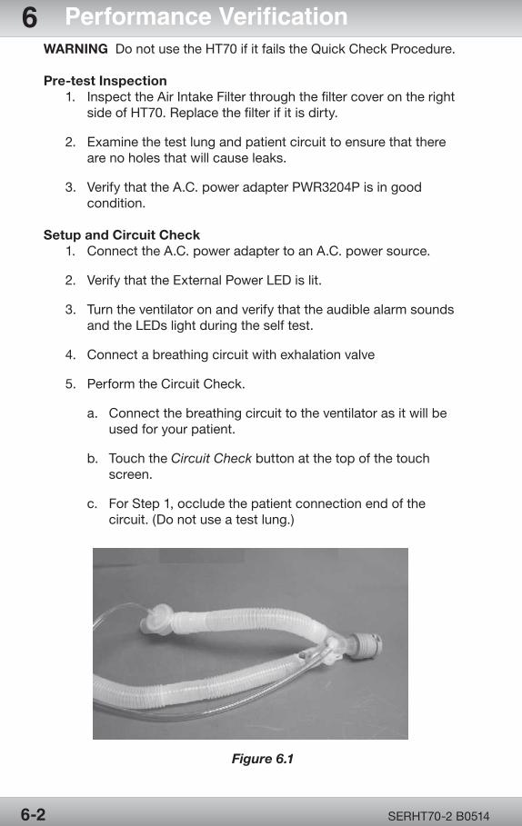
OPR360U A05095-1
5
OPR360U A0509 5-1
5
SERHT70-2 B05146-2
6 Performance VerificationWARNING Do not use the HT70 if it fails the Quick Check Procedure.
Pre-test Inspection 1. InspecttheAirIntakeFilterthroughthefiltercoverontheright sideofHT70.Replacethefilterifitisdirty.
2. Examinethetestlungandpatientcircuittoensurethatthere are no holes that will cause leaks.
3. VerifythattheA.C.poweradapterPWR3204Pisingood condition.
Setup and Circuit Check 1. ConnecttheA.C.poweradaptertoanA.C.powersource.
2. VerifythattheExternalPowerLEDislit.
3. Turntheventilatoronandverifythattheaudiblealarmsounds andtheLEDslightduringtheselftest.
4. Connectabreathingcircuitwithexhalationvalve
5. Perform the Circuit Check.
a. Connect the breathing circuit to the ventilator as it will be usedforyourpatient.
b. Touch the Circuit Check button at the top of the touch screen.
c. ForStep1,occludethepatientconnectionendofthe circuit. (Do not use a test lung.)
Figure 6.1
OPR360U A05095-1
5
OPR360U A0509 5-1
5
SERHT70-2 B0514 6-3
Performance Verification 6 d. Press the Accept button to confirm and start the Circuit Check. e. ForStep2,opentheendofthepatientcircuit.
f. Press the Accept button to continue the Circuit Check.
g. Ifthetestpasses,themessage“CircuitCheckPASSED PressAccepttoConfirm”willbedisplayed.
h. WhentheCircuitCheckiscompleted,presstheAccept button and adjust patient settings as needed and touch the Start Ventilation button to begin ventilation.
i. To cancel the Circuit Check and return to the Startup Screen, press the Cancel button. j. IftheCircuitCheckfails:
i. Themessage“CircuitCheckFAILEDPressAcceptto Confirm”willbedisplayed.
ii. PresstheAcceptbuttontoreturntoStartupScreen.
iii. Restart the Circuit Check.
iv. Check that the accessories and all tubing connections areproperlyconnectedandleakfree.
v. Then touch the Circuit Check button to redo the test.
WARNING Do not use the HT70 if the Circuit Check fails,inadequateventilationmayresult.Useanalternatemethodofventilation.ContactNewportMedicalTechnicalSupport.
NOTE: The Circuit Check results are logged into Event Historyandretainedafterpowerdown.
6. Connectthetestlungtothebreathingcircuit.
7. PresstheBrightnessbuttonandverifythatitscrollsthrough4 levels of brightness. Set the brightness at desired level.
8. Set the ventilator to the following Standard Test Settings as showninTable6.1andpress“StartVentilation”.
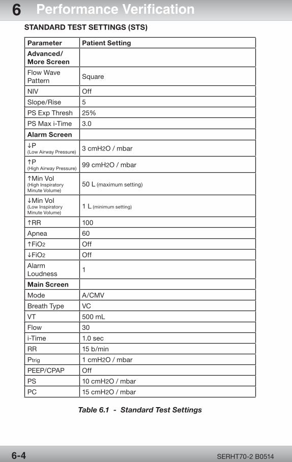
OPR360U A05095-1
5
OPR360U A0509 5-1
5
SERHT70-2 B05146-4
6 Performance Verification
Parameter Patient Setting
Advanced/More Screen
FlowWavePattern
Square
NIV Off
Slope/Rise 5
PSExpThresh 25%
PSMaxi-Time 3.0
Alarm Screen
iP(LowAirwayPressure)
3 cmH2O / mbar
hP(HighAirwayPressure)
99cmH2O / mbar
hMinVol(HighInspiratoryMinuteVolume)
50L(maximumsetting)
iMinVoI(LowInspiratoryMinuteVolume)
1L (minimum setting)
hRR 100
Apnea 60
hFiO2 Off
iFiO2 Off
AlarmLoudness
1
Main Screen
Mode A/CMV
BreathType VC
VT 500mL
Flow 30
i-Time 1.0 sec
RR 15 b/min
Ptrig 1 cmH2O / mbar
PEEP/CPAP Off
PS 10 cmH2O / mbar
PC 15 cmH2O / mbar
STANDARD TEST SETTINGS (STS)
Table 6.1 - Standard Test Settings

OPR360U A05095-1
5
OPR360U A0509 5-1
5
SERHT70-2 B0514 6-5
Performance Verification 6Quick Check Procedure
1) No External Power Alarm Check
a) DisconnecttheA.C.poweradapter.Verifythatthereisan audiblealarmandthealarmLEDsintheHT70handleturnon. VerifythattheExt.PowerLEDturnsoff,andtheMessage AreaturnsyellowanddisplaystheNoExternalPoweralarm message. Confirm that HT70 continues to ventilate.
b) PresstheAlarmSilence/Resetbuttonandconfirmthatits LEDlightsyellow,theaudiblealarmturnsoffandthemessage area returns to black.
c) PresstheAlarmSilence/Resetbuttonagainandconfirmthat the alarm message clears.
d) ReconnecttheA.C.poweradapter.VerifythattheExt.Power LEDlightsgreen.
2) Alarms and Indicators Check
a) High hP Alarm
i) Set the High Paw alarm limit to 20 cmH2O/mbar.Verifythatanaudiblealarmsounds,theREDLEDinthehandleflashes,theHighPawmessagedisplaysandthatinspiration ends when pressure reaches the high limit. Set theHighPawalarmlimitbackto99cmH2O /mbar and verifythattheaudiblealarmstops,theREDLEDinthehandle is cleared and the alarm message remains. Press theAlarmSilence/Resetbuttontoclearthealarmmessage.
b) Low iP Alarm
i) Disconnect the test lung from the breathing circuit andverifythataftertwobreathsanaudiblealarmsoundsandtheCheckCircuitorProxLine/LowPressurealarmmessagedisplays
ii) Attachthetestlungtothebreathingcircuitandverifythatthe audible alarm ceases and the alarm message remains. PressAlarmSilence/Resetbuttontoclearthemessage.
3) Pressure Gauge / PEEP Check
a) Verifythatthepressuregaugemovesupanddownwitheach breath.
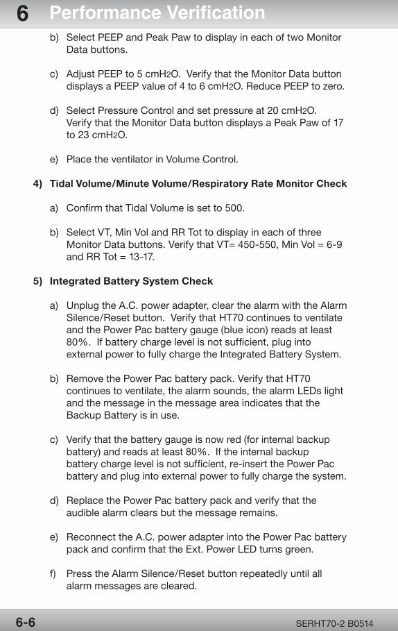
OPR360U A05095-1
5
OPR360U A0509 5-1
5
SERHT70-2 B05146-6
6 Performance Verification b) SelectPEEPandPeakPawtodisplayineachoftwoMonitor Data buttons.
c) AdjustPEEPto5cmH2O.VerifythattheMonitorDatabutton displaysaPEEPvalueof4to6cmH2O.ReducePEEPtozero.
d) Select Pressure Control and set pressure at 20 cmH2O. VerifythattheMonitorDatabuttondisplaysaPeakPawof17 to 23 cmH2O.
e) Place the ventilator in Volume Control.
4) Tidal Volume/Minute Volume/Respiratory Rate Monitor Check
a) Confirm that Tidal Volume is set to 500.
b) SelectVT,MinVolandRRTottodisplayineachofthree MonitorDatabuttons.VerifythatVT=450-550,MinVol=6-9 andRRTot=13-17.
5) Integrated Battery System Check
a) UnplugtheA.C.poweradapter,clearthealarmwiththeAlarm Silence/Resetbutton.VerifythatHT70continuestoventilate andthePowerPacbatterygauge(blueicon)readsatleast 80%.Ifbatterychargelevelisnotsufficient,pluginto externalpowertofullychargetheIntegratedBatterySystem.
b) RemovethePowerPacbatterypack.VerifythatHT70 continuestoventilate,thealarmsounds,thealarmLEDslight and the message in the message area indicates that the BackupBatteryisinuse.
c) Verifythatthebatterygaugeisnowred(forinternalbackup battery)andreadsatleast80%.Iftheinternalbackup batterychargelevelisnotsufficient,re-insertthePowerPac batteryandplugintoexternalpowertofullychargethesystem.
d) ReplacethePowerPacbatterypackandverifythatthe audible alarm clears but the message remains.
e) ReconnecttheA.C.poweradapterintothePowerPacbattery packandconfirmthattheExt.PowerLEDturnsgreen.
f) PresstheAlarmSilence/Resetbuttonrepeatedlyuntilall alarm messages are cleared.
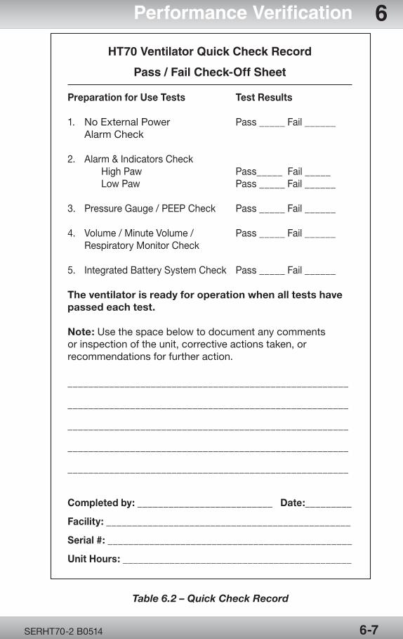
OPR360U A05095-1
5
OPR360U A0509 5-1
5
SERHT70-2 B0514 6-7
Performance Verification 6
HT70 Ventilator Quick Check Record
Pass / Fail Check-Off Sheet
Preparation for Use Tests Test Results
1. NoExternalPower Pass_____Fail______ AlarmCheck
2. Alarm&IndicatorsCheck HighPaw Pass_____Fail_____ LowPaw Pass_____Fail______
3. PressureGauge/PEEPCheck Pass_____Fail______
4. Volume/MinuteVolume/ Pass_____Fail______ RespiratoryMonitorCheck
5. IntegratedBatterySystemCheck Pass_____Fail______
The ventilator is ready for operation when all tests have passed each test.
Note:Usethespacebelowtodocumentanycommentsor inspection of the unit, corrective actions taken, or recommendations for further action.
______________________________________________________
______________________________________________________
______________________________________________________
______________________________________________________
______________________________________________________
Completed by: __________________________ Date: _________
Facility: _______________________________________________ Serial #: _______________________________________________
Unit Hours: ____________________________________________
Table 6.2 – Quick Check Record
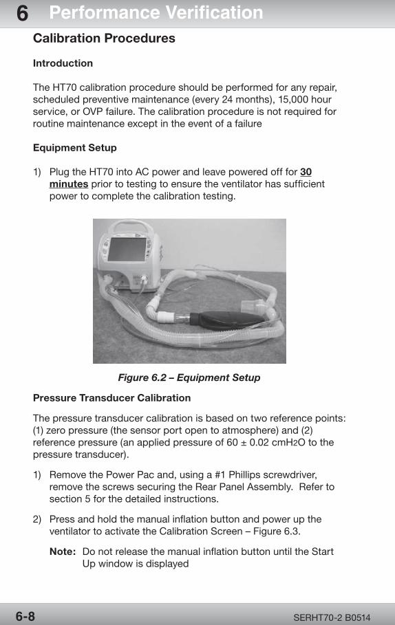
OPR360U A05095-1
5
OPR360U A0509 5-1
5
SERHT70-2 B05146-8
6 Performance VerificationCalibration Procedures
Introduction
TheHT70calibrationprocedureshouldbeperformedforanyrepair,scheduledpreventivemaintenance(every24months),15,000hourservice,orOVPfailure.Thecalibrationprocedureisnotrequiredforroutinemaintenanceexceptintheeventofafailure
Equipment Setup
1) PlugtheHT70intoACpowerandleavepoweredofffor30 minutes prior to testing to ensure the ventilator has sufficient power to complete the calibration testing.
Figure 6.2 – Equipment Setup
Pressure Transducer Calibration
Thepressuretransducercalibrationisbasedontworeferencepoints:(1)zeropressure(thesensorportopentoatmosphere)and(2)referencepressure(anappliedpressureof60±0.02cmH2O to the pressure transducer).
1) Remove the Power Pac and, using a #1 Phillips screwdriver, removethescrewssecuringtheRearPanelAssembly.Referto section 5 for the detailed instructions.
2) Press and hold the manual inflation button and power up the ventilatortoactivatetheCalibrationScreen–Figure6.3.
Note: Do not release the manual inflation button until the Start Upwindowisdisplayed
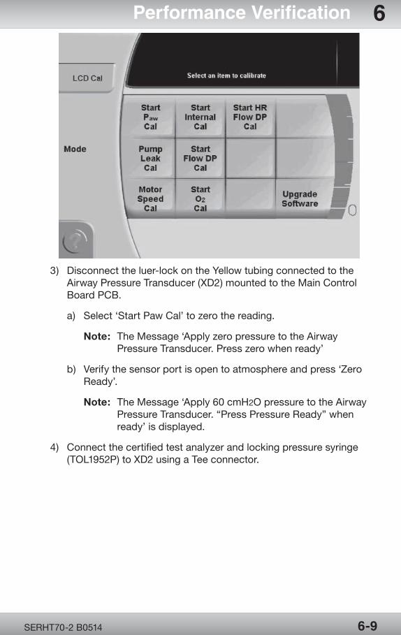
OPR360U A05095-1
5
OPR360U A0509 5-1
5
SERHT70-2 B0514 6-9
Performance Verification 6
Figure 6.3 – Calibration Screen
3) Disconnecttheluer-lockontheYellowtubingconnectedtothe AirwayPressureTransducer(XD2)mountedtotheMainControl Board PCB.
a) Select‘StartPawCal’tozerothereading.
Note: TheMessage‘ApplyzeropressuretotheAirway PressureTransducer.Presszerowhenready’
b) Verifythesensorportisopentoatmosphereandpress‘Zero Ready’.
Note:TheMessage‘Apply60cmH2OpressuretotheAirway PressureTransducer.“PressPressureReady”when ready’isdisplayed.
4) Connectthecertifiedtestanalyzerandlockingpressuresyringe (TOL1952P)toXD2usingaTeeconnector.
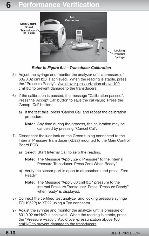
OPR360U A05095-1
5
OPR360U A0509 5-1
5
SERHT70-2 B05146-10
6 Performance Verification
LockingPressureSyringe
Main Control Board
Transducers (XD1 & XD2)
TeeConnector
Refer to Figure 6.4 – Transducer Calibration
5) Adjustthesyringeandmonitortheanalyzeruntilapressureof 60±0.02cmH2Oisachieved.Whenthereadingisstable,press the“PressureReady”.Avoidover-pressurizationabove100 cmH2O to prevent damage to the transducers.
6) Ifthecalibrationispassed,themessage”Calibrationpassed”. Pressthe’AcceptCal’buttontosavethecalvalue;Pressthe ’AcceptCal’button.
a) Ifthetestfails,press‘CancelCal’andrepeatthecalibration procedure.
Note: Anytimeduringtheprocess,thecalibrationmaybe canceledbypressing“CancelCal”.
7) Disconnecttheluer-lockontheGreentubingconnectedtothe InternalPressureTransducer(XD22)mountedtotheMainControl Board PCB.
a) Select‘StartInternalCal’tozerothereading.
Note: TheMessage“ApplyZeroPressure”totheInternal PressureTransducer.PressZeroWhenReady”
b) Verifythesensorportisopentoatmosphereandpress‘Zero Ready’.
Note: TheMessage”Apply60cmH2O“pressuretothe InternalPressureTransducer.Press“PressureReady” whenready’isdisplayed.
8) Connectthecertifiedtestanalyzerandlockingpressuresyringe TOL1952P)toXD22usingaTeeconnector.
9) Adjustthesyringeandmonitortheanalyzeruntilapressureof 60±0.02cmH2Oisachieved.Whenthereadingisstable,press the“PressureReady”.Avoidover-pressurizationabove100 cmH2O to prevent damage to the transducers.
OPR360U A05095-1
5
OPR360U A0509 5-1
5
SERHT70-2 B0514 6-11
Performance Verification 610)Ifthecalibrationispassed,themessage”Calibrationpassed. Pressthe‘AcceptCal’buttontosavethecalvalue”.Pressthe ‘AcceptCal’button.
a) Ifthetestfails,press‘CancelCal’andrepeatthecalibration procedure.
11) Note:Anytimeduringtheprocess,thecalibrationmaybe canceledbypressing“CancelCal”.
12)Reconnecttheluer-locktoXD2andXD22transducerpressuretubes.
13)PowertheHT70offandRreassembletheRearPanelAssembly and reinstall the Power Pac removed in step 21. Renter calibration screen as performed in step 2.
Motor Speed Calibration
1) Disconnect the circuit from the output port
2) Onthecalibrationscreen,select“MotorSpeedCal”.
3) Theunitwillslowlyincreasespeedmotor.Waitapproximately3 minutes for the ventilator to perform and complete this calibration.
Note: If the calibration is passed, the message ‘Calibration passed.Pressthe‘AcceptCal’buttontosavethecalvalue’.
4) Pressthe‘AcceptCal’.
a) Ifthetestfails,press‘CancelCal’andrepeatthecalibration procedure.
Pump Leak Calibration
1) OntheCalibrationscreen,select‘PumpLeakCal’.
Note: TheMessage”AttachtheRp50tothepatientoutlet. Pressthebuttonwhenready”
2) ConnectanRp50parabolicresistortotheMainFlowOutletand DONOTblocktheopenend.
3) Select‘Rp50Ready’.
4) Theunitwillslowlyincreasespeed.Waitfortheventilatorto perform and complete this calibration.
5) Ifthecalibrationispassed,themessage‘Calibrationpassed. Pressthe‘AcceptCal’buttontosavethecalvalue’.
a) Ifthetestfails,press‘CancelCal’andrepeatthecalibration procedure.
OPR360U A05095-1
5
OPR360U A0509 5-1
5
SERHT70-2 B05146-12
6 Performance Verification6) RemoveRP50fromGasOutputandReconnectbreathingcircuit toGasOutput.
FiO2 Sensor Calibration
1) Press the ‘Start O2Cal’button.
2) Press the ‘O2AmbientReady’button.
Note: Duringthetesttheventilatorwilldisplay‘PleaseWait’. Uponcompletion,theventilatorwillstate‘O2 100% Ready’.
3) ConnecttheHT70LowFlowOxygenReservoirtotheventilator.
4) Connect the O2gassourcetoyourflowmeter.(note:makesure the flow meter adjustment knob is in the off position.)
5) Turnontheoxygensourceandturntheflowmeterupto10L/min to flush the reservoir.
6) Pressthe‘O2100%Ready’button.
Note:Duringthetesttheventilatorwilldisplay‘PleaseWait’.
7) Afterthebuttonispressedyouwillneedtoadjusttheflowmeter inordertomaintainasteadyflowofO2goingthroughthesystem.
8) Oncethe“CalibrationPassed”showsonthemessagescreenyou willneedtoadjusttheflowmeterdowntozeroandpressAccept Cal button on the main screen.
9) Disconnectallaccessoriesfromtheairinletport
LCD Calibration
1) Pressthe‘LCDCal’button.
2) Followtheinstructionsasindicatedonthescreen.
Flow Sensor Transducer Calibration Flow Sensor Board GR-PCB3212A Calibration
Note: FlowSensorTransducerCalibrationisonlyrequiredforPLUS units.
1) Select“ClearTubeDPCal”.
2) Confirm transducer is open to atmosphere and select “ZeroReady”.
OPR360U A05095-1
5
OPR360U A0509 5-1
5
SERHT70-2 B0514 6-13
Performance Verification 63) Useaprecisionpressureregulatortoobtainapressureof 1.0 cmH2O.
a) Teeapressuregauge(PTS2000CertifierFAPlus)tothe output of the pressure regulator.
b) Applythepressuretothelowerportoftheflowsensor connector.
c) Adjusttheregulatoruntiltheoutputis1.0cmH2O±0.05.
d) Select“PressureReady”.
4) Select“AcceptCal”,andthenremovethepressure.
5) Select“BlueTubeDPCal”.
6) Confirmtransducerisopentoatmosphereandselect “ZeroReady”.
7) Adjusttheprecisionpressureregulatortoobtainapressureof 2.0 cmH2O.
a) Applythepressuretotheupperportoftheflowsensor connector.
b) Adjusttheregulatoruntiltheoutputis2.0cmH2O±0.05.
c) Select“PressureReady”.
8) Select“AcceptCal”andthenremovethepressure.
9) Uponcompletion,presstheOn/OffSwitchandthe‘Accept’ button to power down the ventilator.
Operational Verification Procedure (OVP)
Note: IftheHT70hasbeenrepaired,hadascheduledPMor15000 hour service performed, or failed during the OVP testing, performafullsystemcalibrationpriortoperformingtheOVP.
Electrical Safety Testing (EST)
1) TheelectricalsafetytestingisnotrequiredastheHT70Ventilator isoperatedonDCpowerfromtheAC/DCpowersupply.
Equipment Setup
1) PlugtheHT70intoACandleaveofffor30 minutes prior to testing to ensure the ventilator has sufficient power to complete the calibration and testing.
OPR360U A05095-1
5
OPR360U A0509 5-1
5
SERHT70-2 B05146-14
6 Performance Verification2) Connect a patient circuit and test lung to the HT70 as showninFigure6.2.
Front Panel Test
1) Press the On/Off switch once. The ventilator performs a self-test. Duringtheself-test,verifythatnoerrormessagesaredisplayed.
2) UsingtheTouchScreen,selectMore>UtilitySettings>Date/Time (ForHT70Plusitistimeandaltitude.Altitudeshouldbesetto0.)
a) UsingtheTouchScreen,touchtheyearanduse pUp/qDownbuttontoselectthecorrectYear.
b) RepeattheabovestepfortheMonth,Day,Hour,andMinute.
3) Whenfinished,selectAccept.4) Pressallmembraneswitchbuttonsandverifythatallbuttonsare functional.
AC Power Loss and Shutdown Buzzer Alarm Test
1) DisconnecttheventilatorfromA.C.power.Verifythe“Lossof ExternalPower,Switchingtobatterypower”alarmisactivated.
2) ShutdowntheventilatorbypressingtheOn/Offswitchonce. Touchthe“Accept”buttononthetouchscreentoconfirm.
3) Verifytheaudibleshutdownalarmactivatesandallowthealarm tocontinueforatleasttwo(2)minutesbeforepressingtheAlarm Silence button.
4) ConnecttheventilatortoA.C.powerandpoweruptheventilator.
Circuit Check
1) Ifthecalibrationprocedureswerenotrequired,performacircuit check as outlined in the Setup and Circuit Check section on page6-2.
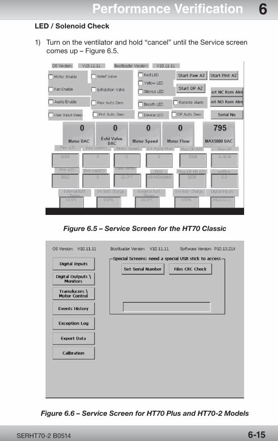
OPR360U A05095-1
5
OPR360U A0509 5-1
5
SERHT70-2 B0514 6-15
Performance Verification 6LED / Solenoid Check
1) Turnontheventilatorandhold“cancel”untiltheServicescreen comesup–Figure6.5.
Figure 6.5 – Service Screen for the HT70 Classic
Figure 6.6 – Service Screen for HT70 Plus and HT70-2 Models
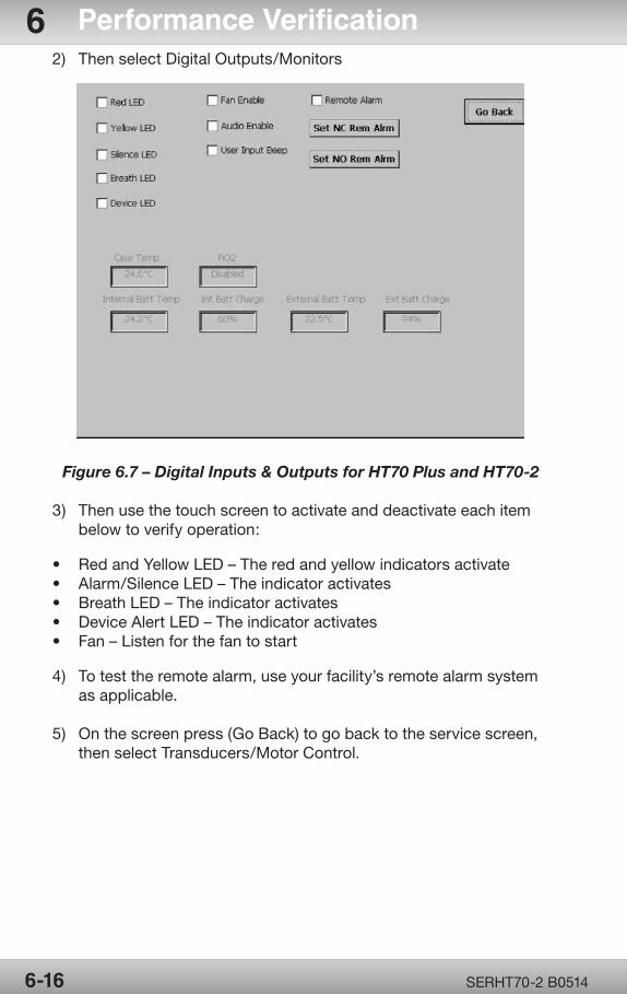
OPR360U A05095-1
5
OPR360U A0509 5-1
5
SERHT70-2 B05146-16
6 Performance Verification2) ThenselectDigitalOutputs/Monitors
Figure 6.7 – Digital Inputs & Outputs for HT70 Plus and HT70-2
3) Then use the touch screen to activate and deactivate each item belowtoverifyoperation:
• RedandYellowLED–Theredandyellowindicatorsactivate• Alarm/SilenceLED–Theindicatoractivates• BreathLED–Theindicatoractivates• DeviceAlertLED–Theindicatoractivates• Fan–Listenforthefantostart
4) Totesttheremotealarm,useyourfacility’sremotealarmsystem as applicable.
5) Onthescreenpress(GoBack)togobacktotheservicescreen, thenselectTransducers/MotorControl.
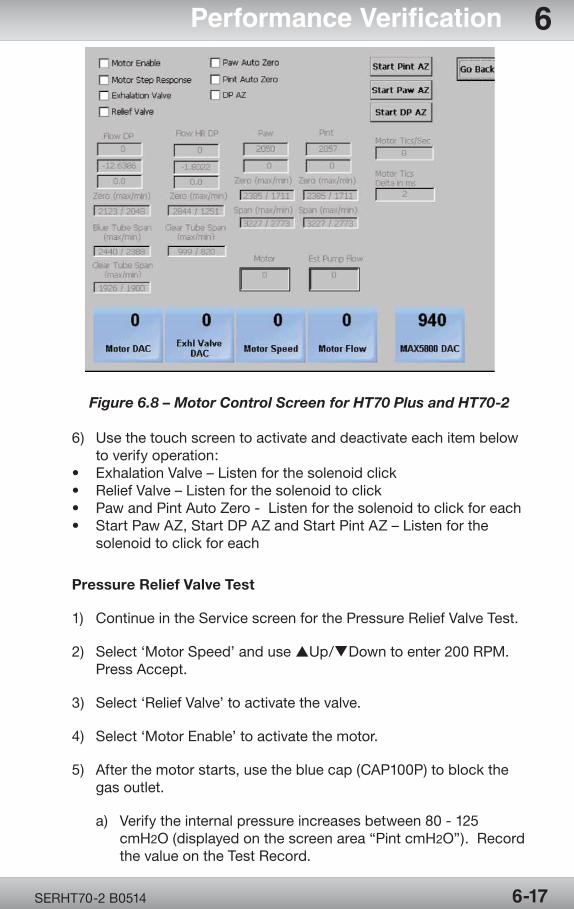
OPR360U A05095-1
5
OPR360U A0509 5-1
5
SERHT70-2 B0514 6-17
Performance Verification 6
Figure 6.8 – Motor Control Screen for HT70 Plus and HT70-2
6) Usethetouchscreentoactivateanddeactivateeachitembelow toverifyoperation:• ExhalationValve–Listenforthesolenoidclick• ReliefValve–Listenforthesolenoidtoclick• PawandPintAutoZero-Listenforthesolenoidtoclickforeach• StartPawAZ,StartDPAZandStartPintAZ–Listenforthe solenoid to click for each
Pressure Relief Valve Test
1) Continue in the Service screen for the Pressure Relief Valve Test.
2) Select‘MotorSpeed’andusepUp/qDowntoenter200RPM. PressAccept.
3) Select‘ReliefValve’toactivatethevalve.
4) Select‘MotorEnable’toactivatethemotor.
5) Afterthemotorstarts,usethebluecap(CAP100P)toblockthe gas outlet.
a) Verifytheinternalpressureincreasesbetween80-125 cmH2O(displayedonthescreenarea“PintcmH2O”).Record the value on the Test Record.
OPR360U A05095-1
5
OPR360U A0509 5-1
5
SERHT70-2 B05146-18
6 Performance Verification b) Verifyallairleakagemustbefromthepressurereliefvalve.
6) Selectthe‘EnableMotor’todeactivatethemotor.
7) Remove the blue cap.
Pressure Verification Test
1) Continue in the Service screen for the Pressure Verification Test.
2) Attachthebreathingcircuittotheventilatorandconnectthe T-connectorfromacalibratedpressureanalyzertothepatient connection.
3) Usethe2bluecapstoblocktheendofthebreathingcircuitand alsoblocktheoutletontheexhalationvalvetoclosethesystem and allow the pressure to build.
4) Select‘MotorEnable’.
5) Verifytheinternal(Pint)andairwaypressure(Paw)displayandthe externalpressureanalyzerarewithin10%ofeachother.Record the values on the Test Record.
6) Selectthe‘EnableMotor’againtodeactivatethemotor.
7) Resetthe‘MotorSpeed’to0andpressAccept.
8) Remove the blue caps.
System Leak Test
1) ContinueintheServicescreenfortheSystemLeakTest.
2) ConnecttheflowmonitortotheMainFlowOutlet
3) SettheMotorFlowto30LpmandpressAccept.
4) Remove the air inlet filter cover and filter.
5) Completelyblocktheinletairformorethan3secondsand measure the flow.
6) Select‘MotorEnable’.
7) Verifytheflowislessthan1Lpm.RecordtheresultsontheTest Record.
OPR360U A05095-1
5
OPR360U A0509 5-1
5
SERHT70-2 B0514 6-19
Performance Verification 68) Selectthe‘EnableMotor’againtodeactivatethemotor.
9) Reinstalltheairinletfilterandcover.
Flow Measurement
1) ContinueintheServicescreenfortheFlowMeasurementTest.
2) ConnecttheflowmonitorbetweentheMainFlowOutletandthe breathing circuit.
3) Select‘ReliefValve’toactivatethevalve.Acheckmarkwillbe displayedtoverifyactivation.
4) Select‘MotorEnable’. a) Verifythemeasuredflowisbetween25.5and34.5Lpm.
b) Record the value on the Test Record.
5) SetMotorFlowto60Lpmandverifythemeasureflowisbetween 51to69Lpm.
6) Selectthe‘MotorEnable’againtodeactivatethemotor.
7) ExittheServiceScreen.
a) PressandholdtheOn/OffSwitchuntilthesystemshutsdown (approximately20seconds).
b) PresstheAlarmSilencebuttontodeactivatethealarm.
Emergency Intake Valve Test
1) Withtheventilatoroff,attachatestlung(LNG600P)totheMain FlowOutlet.
Note:Testlungneedstobedeflatedandsqueezedbefore connecting to the HT70.
2) Verifyaircanbepulledthroughtheemergencyintakevalveby gentlysqueezingthetestlungandcreatinganegativeeffort (vacuum) in the HT70.
3) Remove the test lung
Patient Effort Indicator Test
1) Power up the ventilator with Standard Test Settings and attach breathingcircuitandtestlung(LNG600P)withanRp20.
OPR360U A05095-1
5
OPR360U A0509 5-1
5
SERHT70-2 B05146-20
6 Performance Verification2) Touchthe“StartVentilation”onthetouchscreen.
3) SetRRto1b/minandtriggerbreathsbysqueezingthetestlung hardenoughtocreateanegativepressureequaltoorgreater than 1 cmH2O/mbar.
Note:Negativeeffortsaredisplayedbyayellowbaronthegraph.
4) VerifythePatientEffortIndicator(ontouchscreen)blinksandthe ventilatordeliversamandatorybreatheverysuccessfulsqueeze of the test lung.
5) Set RR to 10 b/min, PEEP to Off, and Ptrig to 0.2 cmH2O/mbar.
a) Verifythatthereisnoauto-triggeringbylookingatRRmonitor and Patient Effort indicator.
6) ChangethesettingstoSPONTmodewithPressuresupportset at 10 and Ptrig to 1 cmH2O.
7) Triggerabreathbysqueezingthetestlung,andverifythe ventilator delivers pressure support breaths.
Pressure Control and PEEP Test
1) SettheventilatortoStandardTestSettings(STS)exceptforthe following:RR10,i-Time3.0,andPtrig 5.0.
2) Attachthecalibrationanalyzerinlinewiththepatientcircuitand thetestlung(LNG600P)withairwayrestrictor(Rp20).
3) Set PC 15 and PEEP 3.
a) VerifytheventilatormonitoredPeakpressureiswithin±2 cmH2OandthePEEPiswithin±1cmH2O of the measured pressures.
4) Set PC 15 and PEEP 5.
a) VerifytheventilatormonitoredPeakpressureiswithin ±2cmH2OandthePEEPiswithin±2cmH2O of the measured pressures. 5) Set PC 30 and PEEP 15.
a) VerifytheventilatormonitoredPeakpressureiswithin ±3cmH2OandthePEEPiswithin±2cmH2O of the measured pressures.
OPR360U A05095-1
5
OPR360U A0509 5-1
5
SERHT70-2 B0514 6-21
Performance Verification 6 Note: Theinspiratorypressureshallbemaintainedduring entireinspirationtime.Toverifythiswatchthebar graph on the monitor.
6) RecordtheresultsontheTestRecord.
FiO2 Verification Test
1) Set the ventilator to Standard Test Settings, with PEEP set to 2 cmH2O,andconnectthetestlung(LNG600P)withanRp20.
2) AttachtheoxygenanalyzertotheMainFlowOutletontheHT70 withaT-Adapterin-linewithyourbreathingcircuit. 3) AttachtheHT70LowFlowReservoirtotheFreshGasInletport andtheflowmeterhosetotheoxygensource.
4) Start ventilation and allow the several breaths to be delivered ateachtoensurestablereadings.RecordtheDisplayedand MeasuredvaluesontheTestRecord
a) Setflowmeterto3LPM,VerifyboththeHT70andCalibratedO2 analyzerarewithin3%ofeachother.b) Setflowmeterto5LPM,VerifyboththeHT70andCalibratedO2 analyzerarewithin3%ofeachother.
5) Turnofftheoxygensource,disconnecttheLowFlowReservoir from the HT70.
Volume Control Test
1) Set the ventilator to Standard Test Settings and connect the test lung(LNG600P)withanRp20.
2) PlacethePTS2000CertifierFAanalyzeratthegasoutletinorder tomeasurethetidalvolume.Waitformeasurementstostabilize.
Note: BesuretheanalyzerissettomeasureusingtheATP (AmbientTemperatureandPressure)parameters.
3) Set the following parameters and record the values on the Test Record.
a) VT200mL/Flow30/iTime0.4s/RR10bpm.Spec:180– 220mL.
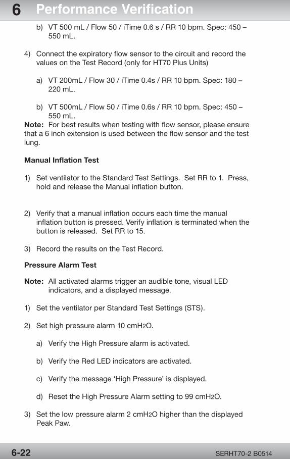
OPR360U A05095-1
5
OPR360U A0509 5-1
5
SERHT70-2 B05146-22
6 Performance Verification b) VT500mL/Flow50/iTime0.6s/RR10bpm.Spec:450– 550mL.
4) Connecttheexpiratoryflowsensortothecircuitandrecordthe valuesontheTestRecord(onlyforHT70PlusUnits)
a) VT200mL/Flow30/iTime0.4s/RR10bpm.Spec:180– 220mL.
b) VT500mL/Flow50/iTime0.6s/RR10bpm.Spec:450– 550mL.Note: Forbestresultswhentestingwithflowsensor,pleaseensurethata6inchextensionisusedbetweentheflowsensorandthetestlung.
Manual Inflation Test
1) Set ventilator to the Standard Test Settings. Set RR to 1. Press, holdandreleasetheManualinflationbutton.
2) Verifythatamanualinflationoccurseachtimethemanual inflationbuttonispressed.Verifyinflationisterminatedwhenthe button is released. Set RR to 15.
3) Record the results on the Test Record.
Pressure Alarm Test
Note: Allactivatedalarmstriggeranaudibletone,visualLED indicators,andadisplayedmessage.
1) Set the ventilator per Standard Test Settings (STS).
2) Set high pressure alarm 10 cmH2O.
a) VerifytheHighPressurealarmisactivated.
b) VerifytheRedLEDindicatorsareactivated.
c) Verifythemessage‘HighPressure’isdisplayed.
d) ResettheHighPressureAlarmsettingto99cmH2O.
3) Set the low pressure alarm 2 cmH2Ohigherthanthedisplayed Peak Paw.
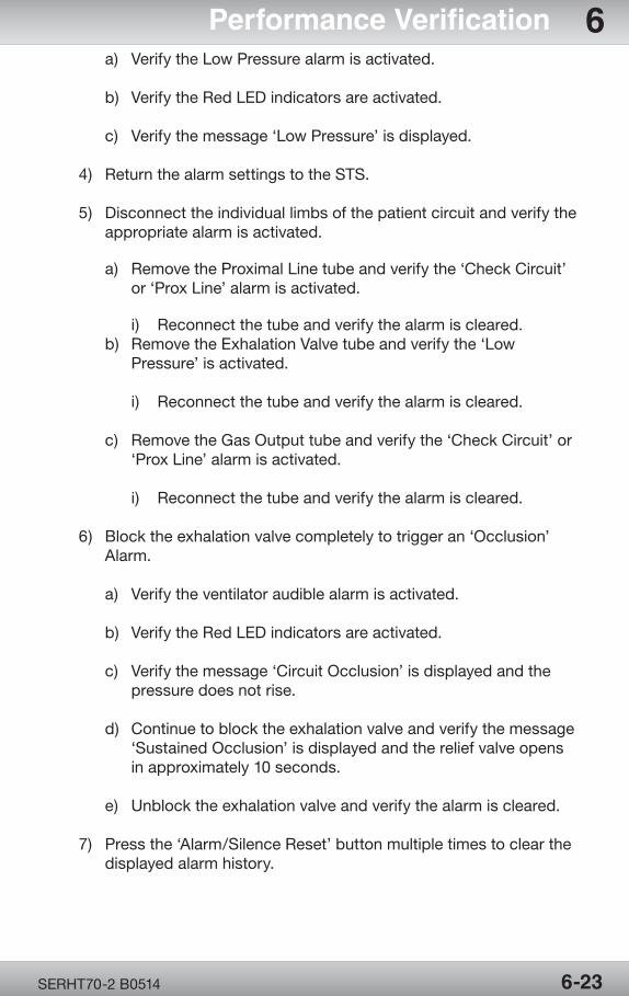
OPR360U A05095-1
5
OPR360U A0509 5-1
5
SERHT70-2 B0514 6-23
Performance Verification 6 a) VerifytheLowPressurealarmisactivated.
b) VerifytheRedLEDindicatorsareactivated.
c) Verifythemessage‘LowPressure’isdisplayed.
4) Return the alarm settings to the STS.
5) Disconnecttheindividuallimbsofthepatientcircuitandverifythe appropriate alarm is activated.
a) RemovetheProximalLinetubeandverifythe‘CheckCircuit’ or‘ProxLine’alarmisactivated.
i) Reconnectthetubeandverifythealarmiscleared. b) RemovetheExhalationValvetubeandverifythe‘Low Pressure’isactivated.
i) Reconnectthetubeandverifythealarmiscleared. c) RemovetheGasOutputtubeandverifythe‘CheckCircuit’or ‘ProxLine’alarmisactivated.
i) Reconnectthetubeandverifythealarmiscleared.
6) Blocktheexhalationvalvecompletelytotriggeran‘Occlusion’ Alarm.
a) Verifytheventilatoraudiblealarmisactivated.
b) VerifytheRedLEDindicatorsareactivated.
c) Verifythemessage‘CircuitOcclusion’isdisplayedandthe pressure does not rise.
d) Continuetoblocktheexhalationvalveandverifythemessage ‘SustainedOcclusion’isdisplayedandthereliefvalveopens inapproximately10seconds.
e) Unblocktheexhalationvalveandverifythealarmiscleared.
7) Pressthe‘Alarm/SilenceReset’buttonmultipletimestoclearthe displayedalarmhistory.
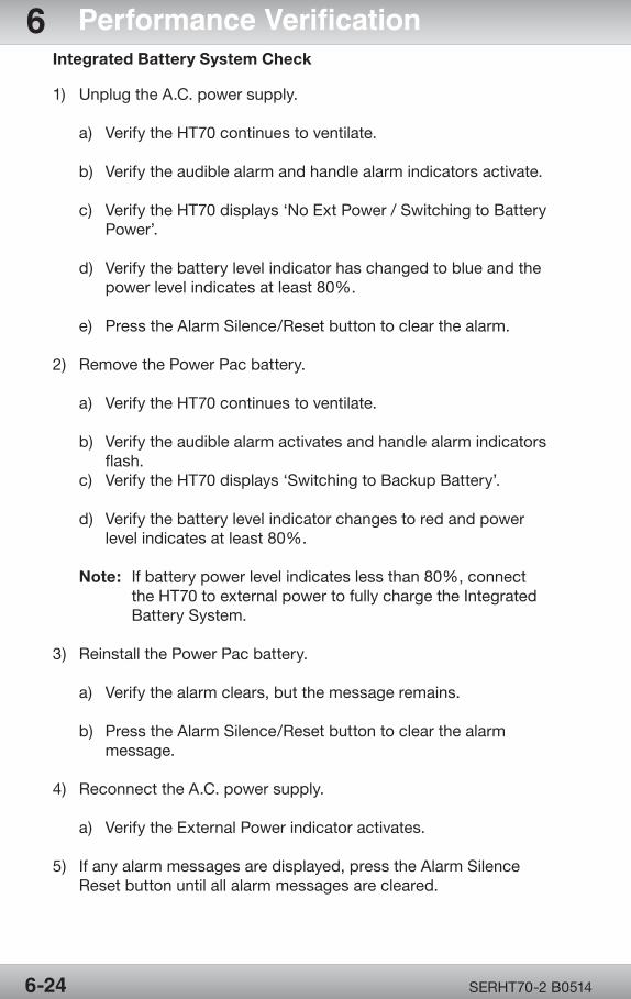
OPR360U A05095-1
5
OPR360U A0509 5-1
5
SERHT70-2 B05146-24
6 Performance VerificationIntegrated Battery System Check
1) UnplugtheA.C.powersupply.
a) VerifytheHT70continuestoventilate.
b) Verifytheaudiblealarmandhandlealarmindicatorsactivate.
c) VerifytheHT70displays‘NoExtPower/SwitchingtoBattery Power’.
d) Verifythebatterylevelindicatorhaschangedtoblueandthe power level indicates at least 80%.
e) PresstheAlarmSilence/Resetbuttontoclearthealarm.
2) RemovethePowerPacbattery.
a) VerifytheHT70continuestoventilate.
b) Verifytheaudiblealarmactivatesandhandlealarmindicators flash. c) VerifytheHT70displays‘SwitchingtoBackupBattery’.
d) Verifythebatterylevelindicatorchangestoredandpower level indicates at least 80%.
Note: Ifbatterypowerlevelindicateslessthan80%,connect theHT70toexternalpowertofullychargetheIntegrated BatterySystem.
3) ReinstallthePowerPacbattery.
a) Verifythealarmclears,butthemessageremains.
b) PresstheAlarmSilence/Resetbuttontoclearthealarm message.
4) ReconnecttheA.C.powersupply.
a) VerifytheExternalPowerindicatoractivates.
5) Ifanyalarmmessagesaredisplayed,presstheAlarmSilence Reset button until all alarm messages are cleared.

TroubleshootingSection 7:
Troubleshooting


OPR360U A05095-1
5
OPR360U A0509 5-1
5
TroubleshootingSection 7:
Table 7.1 Troubleshooting Guide .......................7-1

Page Left Intentionally Blank
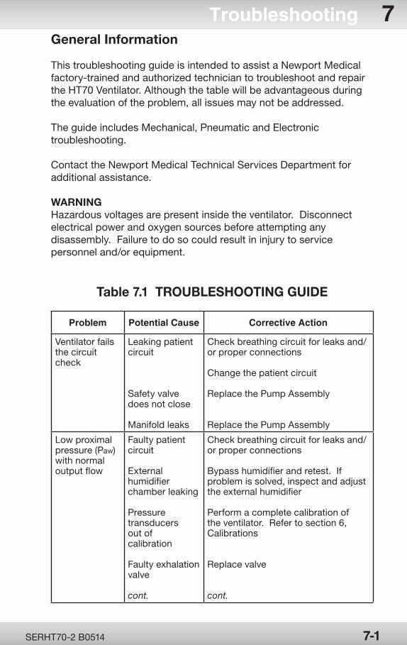
OPR360U A05095-1
5
OPR360U A0509 5-1
5
SERHT70-2 B0514
General Information
This troubleshooting guide is intended to assist a Newport Medical factory-trained and authorized technician to troubleshoot and repair the HT70 Ventilator. Although the table will be advantageous during the evaluation of the problem, all issues may not be addressed.
The guide includes Mechanical, Pneumatic and Electronic troubleshooting.
Contact the Newport Medical Technical Services Department for additional assistance.
WARNINGHazardous voltages are present inside the ventilator. Disconnect electrical power and oxygen sources before attempting any disassembly. Failure to do so could result in injury to service personnel and/or equipment.
Table 7.1 TROUBLESHOOTING GUIDE
Problem Potential Cause Corrective Action
Ventilator fails the circuit check
Leaking patient circuit
Safety valve does not close
Manifold leaks
Check breathing circuit for leaks and/or proper connections
Change the patient circuit
Replace the Pump Assembly
Replace the Pump Assembly
Low proximal pressure (Paw) with normal output flow
Faulty patient circuit
External humidifier chamber leaking
Pressure transducers out of calibration
Faulty exhalation valve
cont.
Check breathing circuit for leaks and/or proper connections
Bypass humidifier and retest. If problem is solved, inspect and adjust the external humidifier
Perform a complete calibration of the ventilator. Refer to section 6, Calibrations
Replace valve
cont.
7-1
Troubleshooting 7
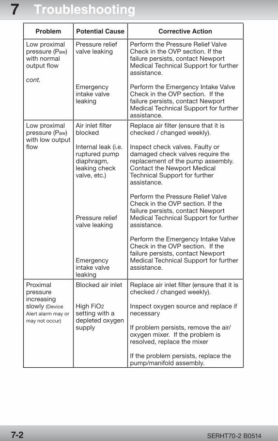
OPR360U A05095-1
5
OPR360U A0509 5-1
5
SERHT70-2 B0514
Problem Potential Cause Corrective Action
Low proximal pressure (Paw) with normal output flow
cont.
Pressure relief valve leaking
Emergency intake valve leaking
Perform the Pressure Relief Valve Check in the OVP section. If the failure persists, contact Newport Medical Technical Support for further assistance.
Perform the Emergency Intake Valve Check in the OVP section. If the failure persists, contact Newport Medical Technical Support for further assistance.
Low proximal pressure (Paw) with low output flow
Air inlet filter blocked
Internal leak (i.e. ruptured pump diaphragm, leaking check valve, etc.)
Pressure relief valve leaking
Emergency intake valve leaking
Replace air filter (ensure that it is checked / changed weekly).
Inspect check valves. Faulty or damaged check valves require the replacement of the pump assembly. Contact the Newport Medical Technical Support for further assistance.
Perform the Pressure Relief Valve Check in the OVP section. If the failure persists, contact Newport Medical Technical Support for further assistance.
Perform the Emergency Intake Valve Check in the OVP section. If the failure persists, contact Newport Medical Technical Support for further assistance.
Proximal pressure increasing slowly (Device Alert alarm may or may not occur)
Blocked air inlet
High FiO2 setting with a depleted oxygen supply
Replace air inlet filter (ensure that it is checked / changed weekly).
Inspect oxygen source and replace if necessary
If problem persists, remove the air/oxygen mixer. If the problem is resolved, replace the mixer
If the problem persists, replace the pump/manifold assembly.
7-2
7 Troubleshooting
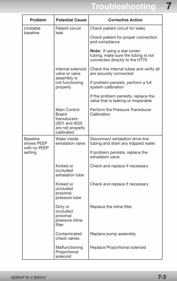
OPR360U A05095-1
5
OPR360U A0509 5-1
5
SERHT70-2 B0514
Problem Potential Cause Corrective Action
Unstable baseline
Patient circuit leak
Internal solenoid valve or valve assembly is not functioning properly
Main Control Board transducers (XD1 and XD2) are not properly calibrated
Check patient circuit for leaks
Check patient for proper connection and compliance
Note: If using a star lumen tubing, make sure the tubing is not connected directly to the HT70
Check the internal tubes and verify all are securely connected
If problem persists, perform a full system calibration
If the problem persists, replace the valve that is leaking or inoperable
Perform the Pressure Transducer Calibration
Baseline shows PEEP with no PEEP setting
Water inside exhalation valve
Kinked or occluded exhalation tube
Kinked or occluded proximal pressure tube
Dirty or occluded proximal pressure inline filter
Contaminated check valves
Malfunctioning Proportional solenoid
Disconnect exhalation drive line tubing and drain any trapped water.
If problem persists, replace the exhalation valve
Check and replace if necessary
Check and replace if necessary
Replace the inline filter
Replace pump assembly
Replace Proportional solenoid
7-3
Troubleshooting 7
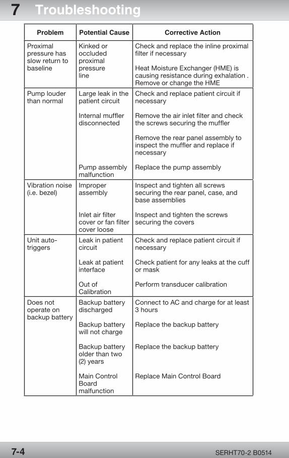
OPR360U A05095-1
5
OPR360U A0509 5-1
5
SERHT70-2 B0514
Problem Potential Cause Corrective Action
Proximal pressure has slow return to baseline
Kinked or occluded proximal pressure line
Check and replace the inline proximal filter if necessary
Heat Moisture Exchanger (HME) is causing resistance during exhalation .Remove or change the HME
Pump louder than normal
Large leak in the patient circuit
Internal muffler disconnected
Pump assembly malfunction
Check and replace patient circuit if necessary
Remove the air inlet filter and check the screws securing the muffler
Remove the rear panel assembly to inspect the muffler and replace if necessary
Replace the pump assembly
Vibration noise (i.e. bezel)
Improper assembly
Inlet air filter cover or fan filter cover loose
Inspect and tighten all screws securing the rear panel, case, and base assemblies
Inspect and tighten the screws securing the covers
Unit auto-triggers
Leak in patient circuit
Leak at patient interface
Out of Calibration
Check and replace patient circuit if necessary
Check patient for any leaks at the cuff or mask
Perform transducer calibration
Does not operate on backup battery
Backup battery discharged
Backup battery will not charge
Backup battery older than two (2) years
Main Control Board malfunction
Connect to AC and charge for at least 3 hours Replace the backup battery
Replace the backup battery
Replace Main Control Board
7-4
7 Troubleshooting
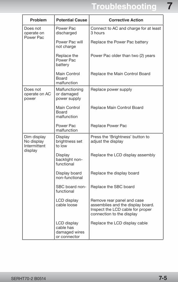
OPR360U A05095-1
5
OPR360U A0509 5-1
5
SERHT70-2 B0514
Problem Potential Cause Corrective Action
Does not operate on Power Pac
Power Pac discharged
Power Pac will not charge
Replace the Power Pac battery
Main Control Board malfunction
Connect to AC and charge for at least 3 hours
Replace the Power Pac battery
Power Pac older than two (2) years
Replace the Main Control Board
Does not operate on AC power
Malfunctioning or damaged power supply
Main Control Board malfunction
Power Pac malfunction
Replace power supply
Replace Main Control Board
Replace Power Pac
Dim displayNo displayIntermittent display
Display brightness set to low
Display backlight non-functional
Display board non-functional
SBC board non-functional
LCD display cable loose
LCD display cable has damaged wires or connector
Press the ‘Brightness’ button to adjust the display
Replace the LCD display assembly
Replace the display board
Replace the SBC board
Remove rear panel and case assemblies and the display board. Inspect the LCD cable for proper connection to the display
Replace the LCD display cable
7-5
Troubleshooting 7
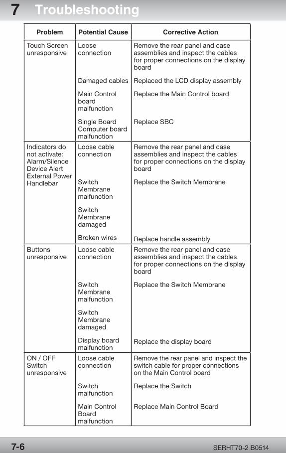
OPR360U A05095-1
5
OPR360U A0509 5-1
5
SERHT70-2 B0514
Problem Potential Cause Corrective Action
Touch Screen unresponsive
Loose connection
Damaged cables
Main Control board malfunction
Single Board Computer board malfunction
Remove the rear panel and case assemblies and inspect the cables for proper connections on the display board
Replaced the LCD display assembly
Replace the Main Control board
Replace SBC
Indicators do not activate:Alarm/SilenceDevice AlertExternal PowerHandlebar
Loose cable connection
Switch Membrane malfunction
Switch Membrane damaged
Broken wires
Remove the rear panel and case assemblies and inspect the cables for proper connections on the display board
Replace the Switch Membrane
Replace handle assembly
Buttons unresponsive
Loose cable connection
Switch Membrane malfunction
Switch Membrane damaged
Display board malfunction
Remove the rear panel and case assemblies and inspect the cables for proper connections on the display board
Replace the Switch Membrane
Replace the display board
ON / OFF Switch unresponsive
Loose cable connection
Switch malfunction
Main Control Board malfunction
Remove the rear panel and inspect the switch cable for proper connections on the Main Control board
Replace the Switch
Replace Main Control Board
7-6
7 Troubleshooting
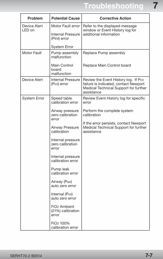
OPR360U A05095-1
5
OPR360U A0509 5-1
5
SERHT70-2 B0514
Problem Potential Cause Corrective Action
Device Alert LED on
Motor Fault error
Internal Pressure (Pint) error
System Error
Refer to the displayed message window or Event History log for additional information
Motor Fault Pump assembly malfunction
Main Control board malfunction
Replace Pump assembly
Replace Main Control board
Device Alert Internal Pressure (Pint) error
Review the Event History log. If Pint failure is indicated, contact Newport Medical Technical Support for further assistance
System Error Speed table calibration error Airway pressure zero calibration error Airway Pressure calibration Internal pressure zero calibration error Internal pressure calibration error Pump leak calibration error Airway (Paw) auto zero error Internal (Pint) auto zero error FiO2 Ambient (21%) calibration error FiO2 100% calibration error
Review Event History log for specific error
Perform the complete system calibration
If the error persists, contact Newport Medical Technical Support for further assistance
7-7
Troubleshooting 7

Page Left Intentionally Blank

Diagrams and Assembly Part Lists
Section 8:
Diagram
s and
Assem
bly P
art Lists

OPR360U A05095-1
5
OPR360U A0509 5-1
5
Diagrams and Assembly Part Lists
Section 8:
Diagram 8.1 - Pneumatics System .................. 8-1Diagram 8.2 - Electronics System ................... 8-2Diagram 8.3 - HT70 Plus Exploded View ........ 8-3Diagram 8.4 - Base Assembly .......................... 8-4Diagram 8.5 - Case Assembly (1 of 7) ............. 8-5Diagram 8.5 - Case Assembly (2 of 7) ............. 8-6Diagram 8.5 - Case Assembly (3 of 7) ............. 8-7Diagram 8.5 - Case Assembly (4 of 7) ............. 8-8Diagram 8.5 - Case Assembly (5 of 7) ............. 8-9Diagram 8.5 - Case Assembly (6 of 7) ............8-10Diagram 8.5 - Case Assembly (7 of 7) ...........8-11

Page Left Intentionally Blank
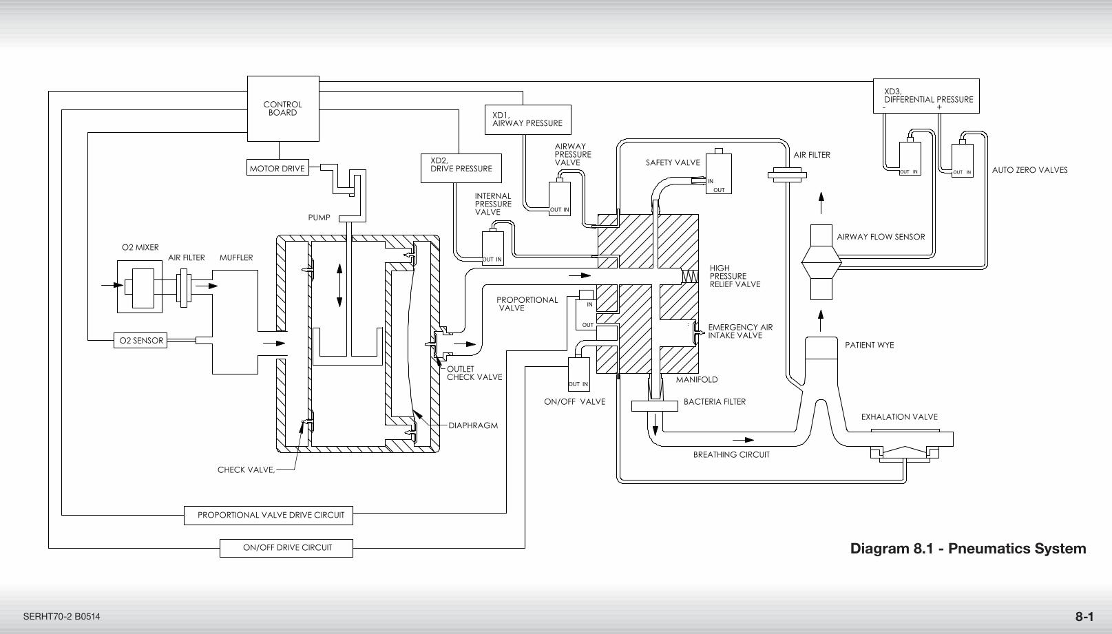
Diagram 8.1 - Pneumatics System
SERHT70-2 B0514 8-1
- +
AUTO ZERO VALVES
AIRWAY FLOW SENSOR
XD3,DIFFERENTIAL PRESSURE
INOUTINOUT
OUTLET CHECK VALVE
SAFETY VALVE
OUT
INPROPORTIONAL VALVE
OUT IN
OUT IN
INOUT
INOUT
O2 SENSOR
AIR FILTER
ON/OFF VALVE
INTERNAL PRESSURE VALVE
AIRWAY PRESSURE VALVE
DIAPHRAGM
XD1, AIRWAY PRESSURE
BACTERIA FILTER
CHECK VALVE,
MUFFLER
AIR FILTER
MANIFOLD
BREATHING CIRCUIT
PATIENT WYE
EMERGENCY AIR INTAKE VALVE
HIGH PRESSURE RELIEF VALVE
EXHALATION VALVE
O2 MIXER
PROPORTIONAL VALVE DRIVE CIRCUIT
ON/OFF DRIVE CIRCUIT
PUMP
XD2, DRIVE PRESSUREMOTOR DRIVE
CONTROLBOARD
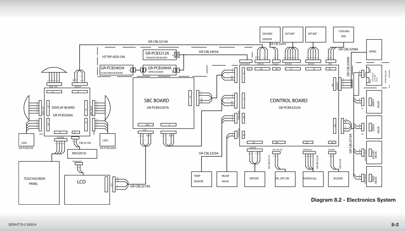
Diagram 8.2 - Electronics System
8-2SERHT70-2 B0514
Z1
SW1
ON_OFF SW
Z3 &
4O
N O
FF V
ALV
E
J16
MOTOR
......
J800
LCD
......
J38
Oxygen
J5
EXT BAT
J5
J3
MEM
_LEF
T
J8
INT BAT
J7
TS PANEL
LCD ......
J2
DISPLAY
......
J27
NURSECALL
J26
SPEA
KERS
PRO
P VA
LVE
J40
TEMP SEN
S
J22
DISPLAY
......
J6
......
J39
Relief Valve
J8
LEDs
J28
BUZZER
BACKLIGHT
J36 ...
J9
LED
s
J35
FAN
Z2
J4
MEM
_RIG
HT
J1
......
J6 ......
J1
......
J6
MEM_TOP
78
1 2
109
34
1 2 11 12
1 2 33 34
12 123456
1 8
12345
12345
1 2 3 4
12
3334
121930
1 2 3 4
1234
12
123
121930
12
4950
12
1234
1 2
1 2
12
910
1234
123
56
12345
12
4950
12
4950
1 2 49 50
12345
DISPLAY BOARD
LCDTOUCHSCREEN
SBC BOARD CONTROL BOARD
EXT BAT INT BAT
LEDs
FAN
ON
OFF
PRO
P
MOTOR
ZERO
1
VA
LVE
ZERO
2
VA
LVE
GR-PCB3206A
GR-PCBA3207A
GR-CBL3214A
GR-CBL3219A
GR-CBL3208A
GR-PCB3204A
ON_OFF SW
VA
LVE
VA
LVE
BUZZER
GR-PCBA3252A
PANEL
GR-
CBL
3216
A
GR-PCB3204
NURSECALL
LEDs
COOLING
RELIEF VALVE
TEMP SENSOR
GR-CBL3220A
CBL
3210
A
GR-
CBL
3223
A
GR-
CBL
3217
A
OXYGEN SENSOR
GR-CBL3200A
INV3201A
CBL3213A
GR-PCB3404ABYPASS BOARD
GR-PCB3403AFLOW SENSOR BOARD
J1J1
01
J100
GR-PCB3212ATRANSDUCER BOARD
J1
FLOW SENSOR
J42
HT70P ADD-ON
GR-
CBL
3209
A
ZERO
3ZE
RO4
FLO
W S
ENSO
RA
UTO
ZER
O
VAVL
ES
SPKRS
HT7
0P A
DD
-ON
GR-CBL3403A
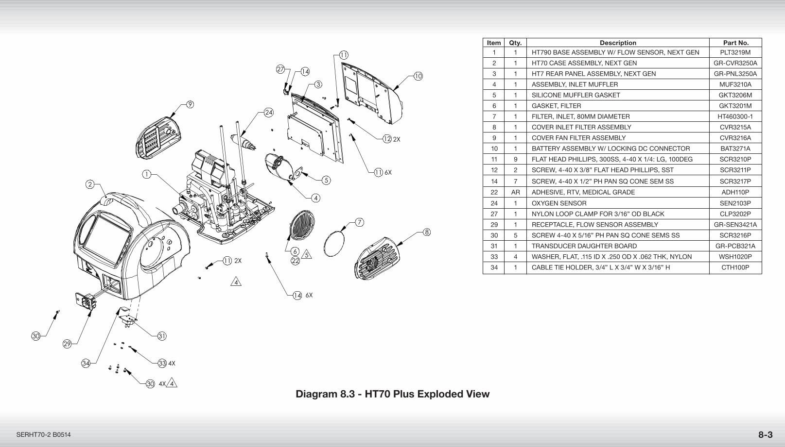
Item Qty. Description Part No. 1 1 HT790 BaSE aSSEmBly w/ Flow SEnSoR, nExT GEn PlT3219m
2 1 HT70 CaSE aSSEmBly, nExT GEn GR-CVR3250a
3 1 HT7 REaR PanEl aSSEmBly, nExT GEn GR-Pnl3250a
4 1 aSSEmBly, InlET muFFlER muF3210a
5 1 SIlIConE muFFlER GaSkET GkT3206m
6 1 GaSkET, FIlTER GkT3201m
7 1 FIlTER, InlET, 80mm DIamETER HT460300-1
8 1 CoVER InlET FIlTER aSSEmBly CVR3215a
9 1 CoVER Fan FIlTER aSSEmBly CVR3216a
10 1 BaTTERy aSSEmBly w/ loCkInG DC ConnECToR BaT3271a
11 9 FlaT HEaD PHIllIPS, 300SS, 4-40 x 1/4: lG, 100DEG SCR3210P
12 2 SCREw, 4-40 x 3/8” FlaT HEaD PHIllIPS, SST SCR3211P
14 7 SCREw, 4-40 x 1/2” PH Pan Sq ConE SEm SS SCR3217P
22 aR aDHESIVE, RTV, mEDICal GRaDE aDH110P
24 1 oxyGEn SEnSoR SEn2103P
27 1 nylon looP ClamP FoR 3/16” oD BlaCk ClP3202P
29 1 RECEPTaClE, Flow SEnSoR aSSEmBly GR-SEn3421a
30 5 SCREw 4-40 x 5/16” PH Pan Sq ConE SEmS SS SCR3216P
31 1 TRanSDuCER DauGHTER BoaRD GR-PCB321a
33 4 waSHER, FlaT, .115 ID x .250 oD x .062 THk, nylon wSH1020P
34 1 CaBlE TIE HolDER, 3/4” l x 3/4” w x 3/16” H CTH100P
Diagram 8.3 - HT70 Plus Exploded View
8-3SERHT70-2 B0514
4
12
7
14
1
11 2X
6X
6X
2X
6 522
4
10
52
9
8
11
24
3
11
27 14
2930 31
30 4X
33 4X
4
34
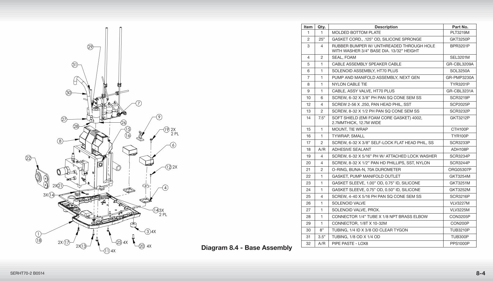
Diagram 8.4 - Base Assembly
8-4SERHT70-2 B0514
1
18 1713
11
2520
3
4
12
6
1915
7
9
16
21
8
22
143X
14 3X2 PL
2627
28
29
30
31
2X2X
4X
4X4X
4X
2X
2X
2X
2 PL
Item Qty. Description Part No. 1 1 molDED BoTTom PlaTE PlT3219m
2 25” GaSkET CoRD., .125” oD, SIlIConE SPRonGE GkT3250P
3 4 RuBBER BumPER w/ unTHREaDED THRouGH HolE BPR3201P wITH waSHER 3/4” BaSE DIa. 13/32” HEIGHT
4 2 SEal, Foam SEl3201m
5 1 CaBlE aSSEmBly SPEakER CaBlE GR-CBl3209a
6 1 SolEnoID aSSEmBly, HT70 PluS Sol3250a
7 1 PumP anD manIFolD aSSEmBly, nExT GEn GR-PmP3230a
8 1 nylon CaBlE TIE TyR3201P
9 1 CaBlE, aSSy ValVE, HT70 PluS GR-CBl3231a
10 6 SCREw, 6-32 x 3/8” PH Pan Sq ConE SEm SS SCR3219P
12 4 SCREw 2-56 x .250, Pan HEaD PHIl, SST SCP2025P
13 2 SCREw, 8-32 x 1/2 PH Pan Sq ConE SEm SS SCR3232P
14 7.5” SoFT SHIElD (EmI Foam CoRE GaSkET) 4002, GkT3212P 2.7mmTHICk, 12.7m wIDE
15 1 mounT, TIE wRaP CTH100P
16 1 TywRaP, Small TyR100P
17 2 SCREw, 6-32 x 3/8” SElF-loCk FlaT HEaD PHIl, SS SCR3233P
18 a/R aDHESIVE SEalanT aDH108P
19 4 SCREw, 6-32 x 5/16” PH w/ aTTaCHED loCk waSHER SCR3234P
20 4 SCREw, 8-32 x 1/2” Pan HD PHIllIPS, SST, nylon SCR3244P
21 2 o-RInG, Buna-n, 70a DuRomETER oRG05307P
22 1 GaSkET, PumP manIFolD ouTlET GkT3254m
23 1 GaSkET SlEEVE, 1.00” oD, 0.75” ID, SIlIConE GkT3251m
24 1 GaSkET SlEEVE, 0.75” oD, 0.50” ID, SIlIConE GkT3252m
25 4 SCREw, 4-40 x 5/16 PH Pan Sq ConE SEm SS SCR3216P
26 1 SolEnoID ValVE VlV3227m
27 1 SolEnoID ValVE, PRox. VlV3225m
28 1 ConnECToR 1/4” TuBE x 1/8 nPT BRaSS ElBow Con3205P
29 1 ConnECToR, 1/8T x 10-32m Con200P
30 8” TuBInG, 1/4 ID x 3/8 oD ClEaR TyGon TuB3210P
31 3.5” TuBInG, 1/8 oD x 1/4 oD TuB300P
32 a/R PIPE PaSTE - lox8 PPS1000P
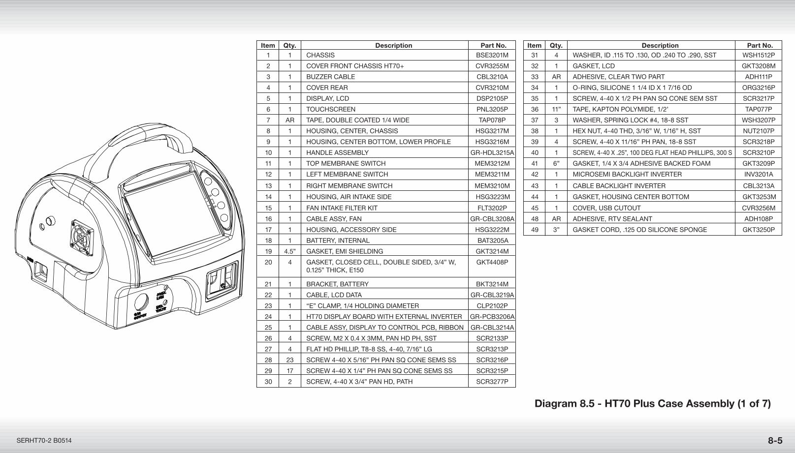
8-5
Diagram 8.5 - HT70 Plus Case Assembly (1 of 7)
SERHT70-2 B0514
Item Qty. Description Part No. 1 1 CHaSSIS BSE3201m
2 1 CoVER FRonT CHaSSIS HT70+ CVR3255m
3 1 BuzzER CaBlE CBl3210a
4 1 CoVER REaR CVR3210m
5 1 DISPlay, lCD DSP2105P
6 1 TouCHSCREEn Pnl3205P
7 aR TaPE, DouBlE CoaTED 1/4 wIDE TaP078P
8 1 HouSInG, CEnTER, CHaSSIS HSG3217m
9 1 HouSInG, CEnTER BoTTom, lowER PRoFIlE HSG3216m
10 1 HanDlE aSSEmBly GR-HDl3215a
11 1 ToP mEmBRanE SwITCH mEm3212m
12 1 lEFT mEmBRanE SwITCH mEm3211m
13 1 RIGHT mEmBRanE SwITCH mEm3210m
14 1 HouSInG, aIR InTakE SIDE HSG3223m
15 1 Fan InTakE FIlTER kIT FlT3202P
16 1 CaBlE aSSy, Fan GR-CBl3208a
17 1 HouSInG, aCCESSoRy SIDE HSG3222m
18 1 BaTTERy, InTERnal BaT3205a
19 4.5” GaSkET, EmI SHIElDInG GkT3214m
20 4 GaSkET, CloSED CEll, DouBlE SIDED, 3/4” w, GkT4408P 0.125” THICk, E150
21 1 BRaCkET, BaTTERy BkT3214m
22 1 CaBlE, lCD DaTa GR-CBl3219a
23 1 “E” ClamP, 1/4 HolDInG DIamETER ClP2102P
24 1 HT70 DISPlay BoaRD wITH ExTERnal InVERTER GR-PCB3206a
25 1 CaBlE aSSy, DISPlay To ConTRol PCB, RIBBon GR-CBl3214a
26 4 SCREw, m2 x 0.4 x 3mm, Pan HD PH, SST SCR2133P
27 4 FlaT HD PHIllIP, T8-8 SS, 4-40, 7/16” lG SCR3213P
28 23 SCREw 4-40 x 5/16” PH Pan Sq ConE SEmS SS SCR3216P
29 17 SCREw 4-40 x 1/4” PH Pan Sq ConE SEmS SS SCR3215P
30 2 SCREw, 4-40 x 3/4” Pan HD, PaTH SCR3277P
Item Qty. Description Part No. 31 4 waSHER, ID .115 To .130, oD .240 To .290, SST wSH1512P
32 1 GaSkET, lCD GkT3208m
33 aR aDHESIVE, ClEaR Two PaRT aDH111P
34 1 o-RInG, SIlIConE 1 1/4 ID x 1 7/16 oD oRG3216P
35 1 SCREw, 4-40 x 1/2 PH Pan Sq ConE SEm SST SCR3217P
36 11” TaPE, kaPTon PolymIDE, 1/2’ TaP077P
37 3 waSHER, SPRInG loCk #4, 18-8 SST wSH3207P
38 1 HEx nuT, 4-40 THD, 3/16” w, 1/16” H, SST nuT2107P
39 4 SCREw, 4-40 x 11/16” PH Pan, 18-8 SST SCR3218P
40 1 SCREw, 4-40 x .25”, 100 DEG FlaT HEaD PHIllIPS, 300 S SCR3210P
41 6” GaSkET, 1/4 x 3/4 aDHESIVE BaCkED Foam GkT3209P
42 1 mICRoSEmI BaCklIGHT InVERTER InV3201a
43 1 CaBlE BaCklIGHT InVERTER CBl3213a
44 1 GaSkET, HouSInG CEnTER BoTTom GkT3253m
45 1 CoVER, uSB CuTouT CVR3256m
48 aR aDHESIVE, RTV SEalanT aDH108P
49 3” GaSkET CoRD, .125 oD SIlIConE SPonGE GkT3250P
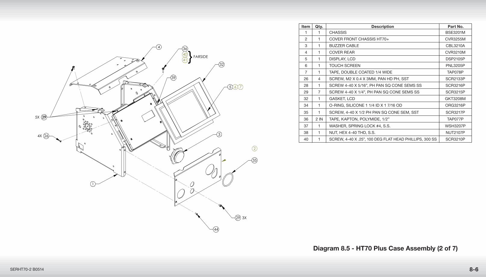
8-6SERHT70-2 B0514
35
2
32
5 6 7
4 36
4041
292929
26
1
39
29
44
5X
4X
3X
} FARSIDE
3
Item Qty. Description Part No. 1 1 CHaSSIS BSE3201m
2 1 CoVER FRonT CHaSSIS HT70+ CVR3255m
3 1 BuzzER CaBlE CBl3210a
4 1 CoVER REaR CVR3210m
5 1 DISPlay, lCD DSP2105P
6 1 TouCH SCREEn Pnl3205P
7 1 TaPE, DouBlE CoaTED 1/4 wIDE TaP078P
26 4 SCREw, m2 x 0.4 x 3mm, Pan HD PH, SST SCR2133P
28 1 SCREw 4-40 x 5/16”, PH Pan Sq ConE SEmS SS SCR3216P
29 7 SCREw 4-40 x 1/4”, PH Pan Sq ConE SEmS SS SCR3215P
32 1 GaSkET, lCD GkT3208m
34 1 o-RInG, SIlIConE 1 1/4 ID x 1 7/16 oD oRG3216P
35 1 SCREw, 4-40 x 1/2 PH Pan Sq ConE SEm, SST SCR3217P
36 2 In TaPE, kaPTon, PolymIDE, 1/2” TaP077P
37 1 waSHER, SPRInG loCk #4, S.S. wSH3207P
38 1 nuT, HEx 4-40 THD, S.S. nuT2107P
40 1 SCREw, 4-40 x .25”, 100 DEG FlaT HEaD PHIllIPS, 300 SS SCR3210P
Diagram 8.5 - HT70 Plus Case Assembly (2 of 7)
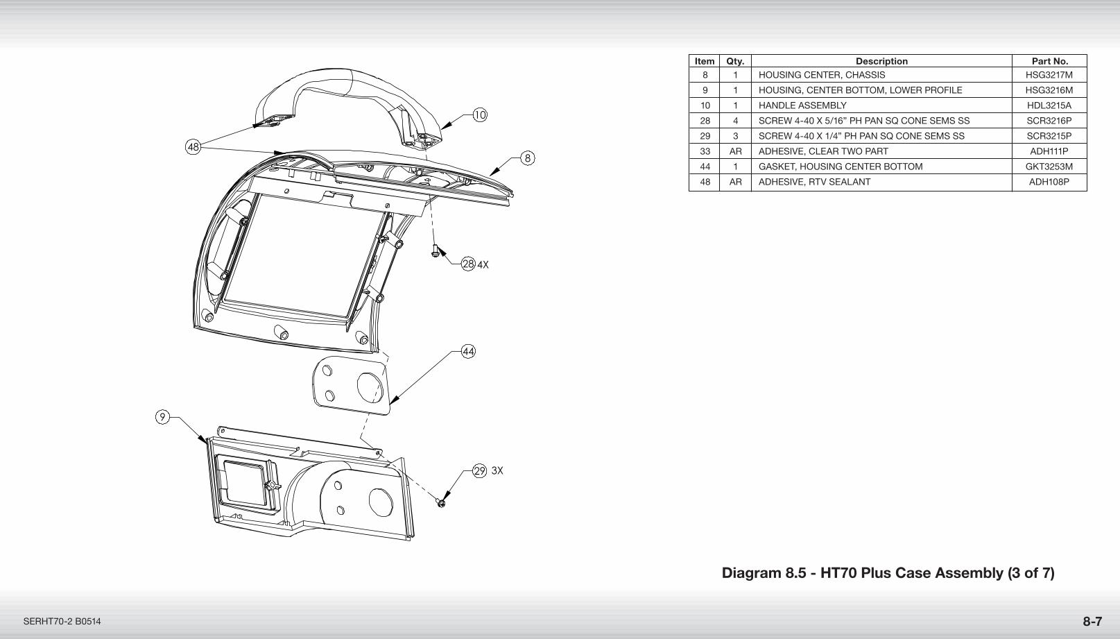
8-7SERHT70-2 B0514
9
8
10
28
29
4X
3X
44
48
Diagram 8.5 - HT70 Plus Case Assembly (3 of 7)
Item Qty. Description Part No. 8 1 HouSInG CEnTER, CHaSSIS HSG3217m
9 1 HouSInG, CEnTER BoTTom, lowER PRoFIlE HSG3216m
10 1 HanDlE aSSEmBly HDl3215a
28 4 SCREw 4-40 x 5/16” PH Pan Sq ConE SEmS SS SCR3216P
29 3 SCREw 4-40 x 1/4” PH Pan Sq ConE SEmS SS SCR3215P
33 aR aDHESIVE, ClEaR Two PaRT aDH111P
44 1 GaSkET, HouSInG CEnTER BoTTom GkT3253m
48 aR aDHESIVE, RTV SEalanT aDH108P
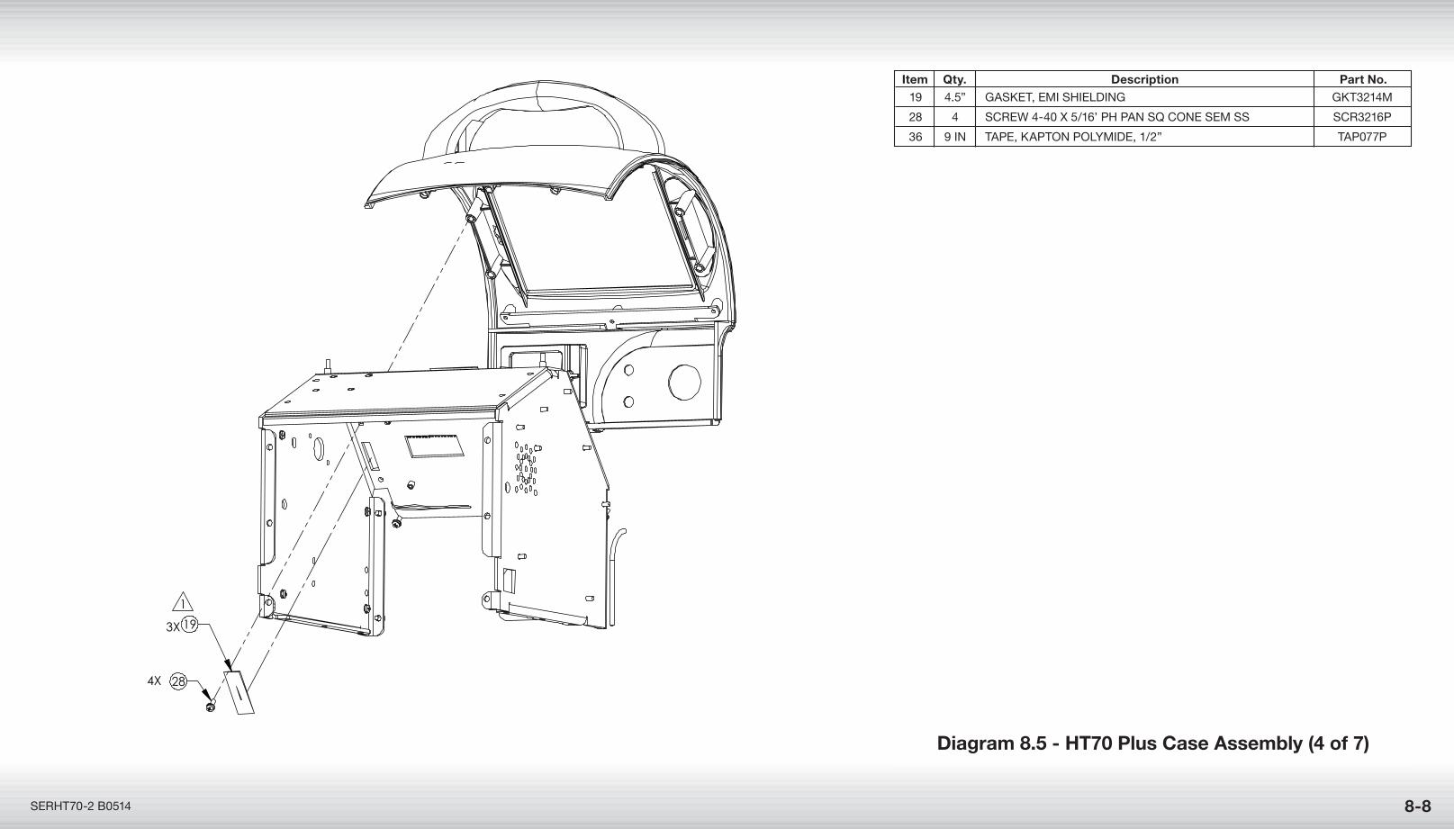
8-8SERHT70-2 B0514
284X
19
1
3X
Diagram 8.5 - HT70 Plus Case Assembly (4 of 7)
Item Qty. Description Part No. 19 4.5” GaSkET, EmI SHIElDInG GkT3214m
28 4 SCREw 4-40 x 5/16’ PH Pan Sq ConE SEm SS SCR3216P
36 9 In TaPE, kaPTon PolymIDE, 1/2” TaP077P
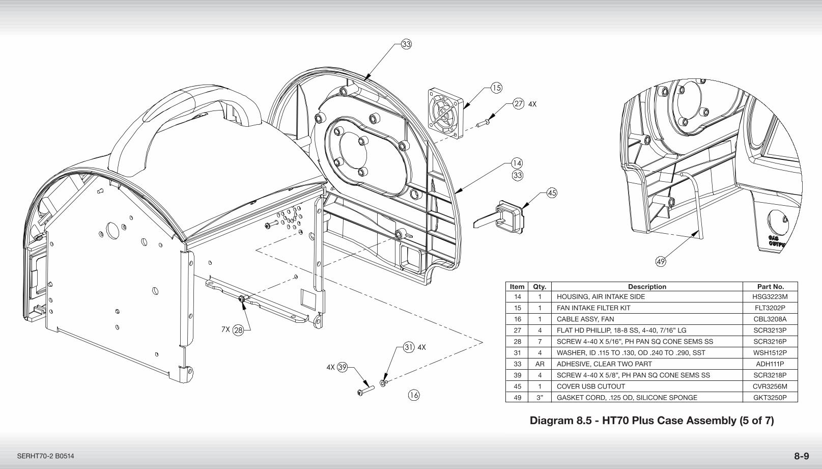
15
27
16
31
28
14
7X
4X
4X
4X 39
33
33
45
49
8-9SERHT70-2 B0514
Diagram 8.5 - HT70 Plus Case Assembly (5 of 7)
Item Qty. Description Part No. 14 1 HouSInG, aIR InTakE SIDE HSG3223m
15 1 Fan InTakE FIlTER kIT FlT3202P
16 1 CaBlE aSSy, Fan CBl3208a
27 4 FlaT HD PHIllIP, 18-8 SS, 4-40, 7/16” lG SCR3213P
28 7 SCREw 4-40 x 5/16”, PH Pan Sq ConE SEmS SS SCR3216P
31 4 waSHER, ID .115 To .130, oD .240 To .290, SST wSH1512P
33 aR aDHESIVE, ClEaR Two PaRT aDH111P
39 4 SCREw 4-40 x 5/8”, PH Pan Sq ConE SEmS SS SCR3218P
45 1 CoVER uSB CuTouT CVR3256m
49 3” GaSkET CoRD, .125 oD, SIlIConE SPonGE GkT3250P
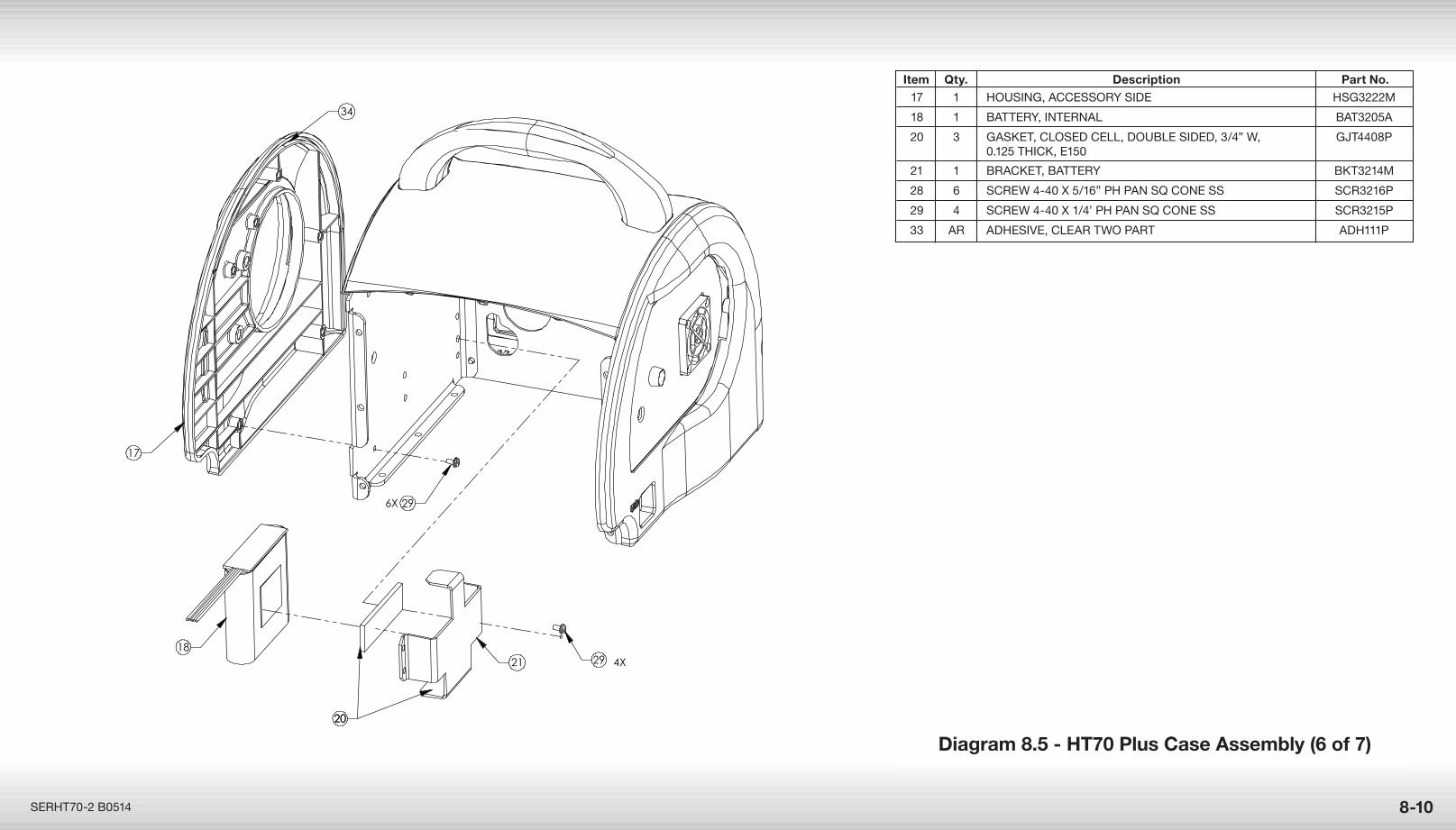
8-10SERHT70-2 B0514
Diagram 8.5 - HT70 Plus Case Assembly (6 of 7)
1821 29
17
296X
4X
2020
34
Item Qty. Description Part No. 17 1 HouSInG, aCCESSoRy SIDE HSG3222m
18 1 BaTTERy, InTERnal BaT3205a
20 3 GaSkET, CloSED CEll, DouBlE SIDED, 3/4” w, GjT4408P 0.125 THICk, E150
21 1 BRaCkET, BaTTERy BkT3214m
28 6 SCREw 4-40 x 5/16” PH Pan Sq ConE SS SCR3216P
29 4 SCREw 4-40 x 1/4’ PH Pan Sq ConE SS SCR3215P
33 aR aDHESIVE, ClEaR Two PaRT aDH111P
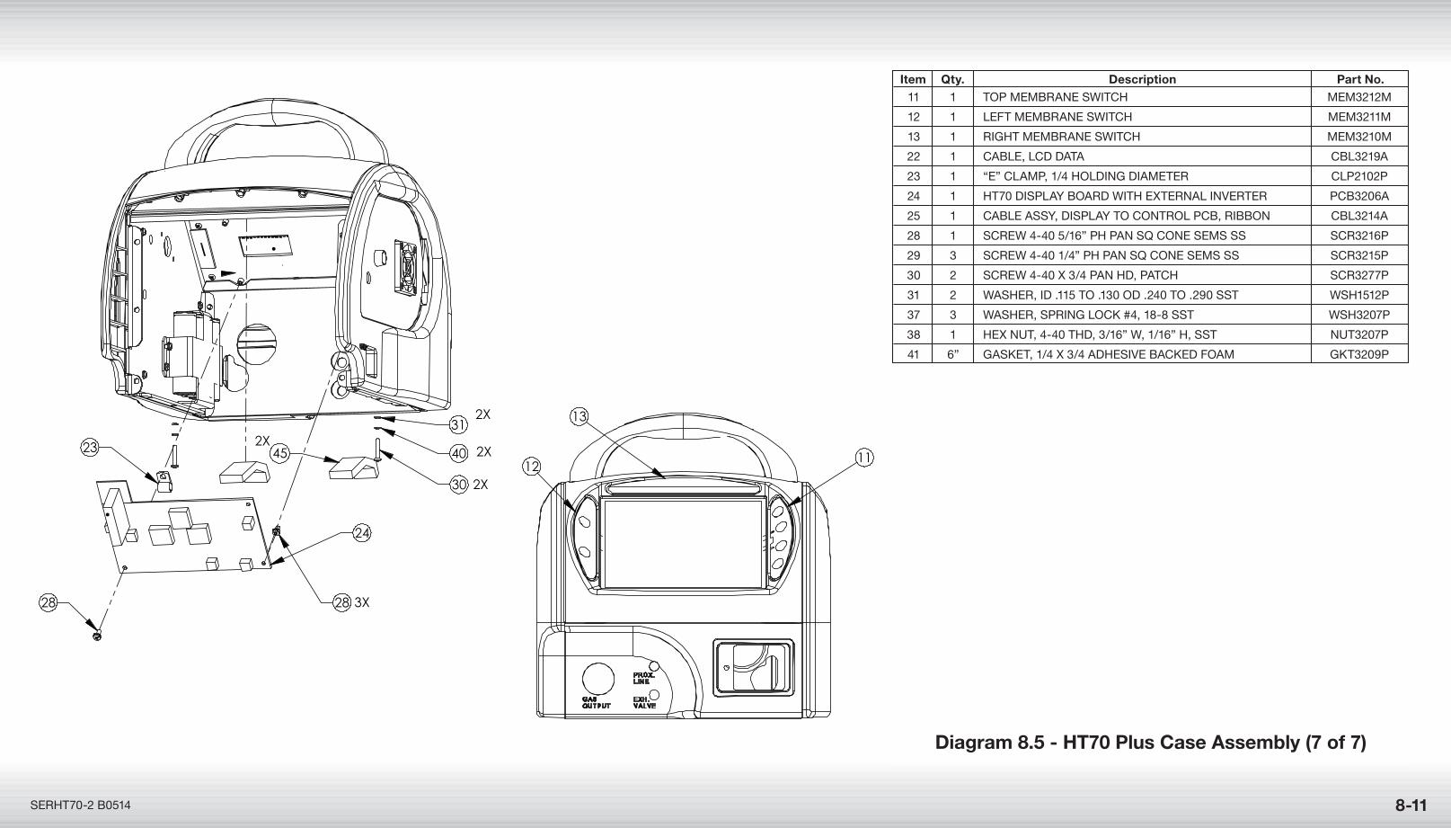
8-11SERHT70-2 B0514
Diagram 8.5 - HT70 Plus Case Assembly (7 of 7)
23
24
28 3X
30 2X
31
40 2X45
28
11
13
12
2X
2X
23
24
28 3X
30 2X
31
40 2X45
28
11
13
12
2X
2X
Item Qty. Description Part No. 11 1 ToP mEmBRanE SwITCH mEm3212m
12 1 lEFT mEmBRanE SwITCH mEm3211m
13 1 RIGHT mEmBRanE SwITCH mEm3210m
22 1 CaBlE, lCD DaTa CBl3219a
23 1 “E” ClamP, 1/4 HolDInG DIamETER ClP2102P
24 1 HT70 DISPlay BoaRD wITH ExTERnal InVERTER PCB3206a
25 1 CaBlE aSSy, DISPlay To ConTRol PCB, RIBBon CBl3214a
28 1 SCREw 4-40 5/16” PH Pan Sq ConE SEmS SS SCR3216P
29 3 SCREw 4-40 1/4” PH Pan Sq ConE SEmS SS SCR3215P
30 2 SCREw 4-40 x 3/4 Pan HD, PaTCH SCR3277P
31 2 waSHER, ID .115 To .130 oD .240 To .290 SST wSH1512P
37 3 waSHER, SPRInG loCk #4, 18-8 SST wSH3207P
38 1 HEx nuT, 4-40 THD, 3/16” w, 1/16” H, SST nuT3207P
41 6” GaSkET, 1/4 x 3/4 aDHESIVE BaCkED Foam GkT3209P

Page left Intentionally Blank